Article

A Dual-Function Instantaneous Power Theory for Operation of Three-Level Neutral-Point-Clamped Inverter-Based Shunt Active Power Filter

1
Department of Electrical and Electronic Engineering, Faculty of Engineering, Universiti Putra Malaysia, Serdang 43400, Malaysia
2
Centre for Advanced Power and Energy Research (CAPER), Faculty of Engineering, Universiti Putra Malaysia, Serdang 43400, Malaysia
*
Author to whom correspondence should be addressed.
Energies 2018, 11(6), 1592; https://doi.org/10.3390/en11061592
Submission received: 10 May 2018 / Revised: 25 May 2018 / Accepted: 2 June 2018 / Published: 18 June 2018

Abstract

:
This paper proposes a simple yet effective reference current generation algorithm based on instantaneous power p q theory to enhance mitigation performance of a three-phase three-level neutral-point-clamped (NPC) inverter-based shunt active power filter (SAPF). The proposed algorithm is developed for dual functionality: generate reference current and synchronization phase to effectively govern operation of SAPF in mitigating harmonic current and compensating reactive power. Three key modifications are implemented: (1) replacement of numerical low-pass filter (LPF) with an average power detector to improve mitigation performance; (2) removal of needless reactive element to reduce algorithm complexity; and (3) integration of phase tracking feature to eliminate the needs of phase-locked loop (PLL). Simulation work of SAPF with the proposed algorithm was conducted and assessed in MATLAB–Simulink. In addition, to verify feasibility of the proposed algorithm, a laboratory prototype as constructed with TMS320F28335 digital signal processor (DSP) programmed as the controller. Performance of SAPF achieved by utilizing the proposed algorithm was thoroughly investigated and benchmarked with that demonstrated using the existing p q theory algorithm to evaluate the inherent advantages. Simulation and experimental results are obtained for different nonlinear loads and test conditions. Responses demonstrated by SAPF in both simulation and experimental works reveal superiority of the proposed algorithm over the existing algorithm.

1. Introduction

High current harmonics resulted from broad utilizations of nonlinear loads is one of the noteworthy power quality issues in electrical power system which has attracted huge research interests. Other than deteriorating the overall power system efficiency through reduction of power factor (PF), the presence of harmonic currents may also cause capacitor blowing, malfunction of sensitive devices, and equipment overheating [1,2]. As a result, it is obligatory to limit harmonic contents in power system and maintain it at an acceptable level. In fact, various innovative techniques have been proposed in the literature [3] to reduce the impacts of harmonic currents, where shunt active power filter (SAPF) is found to be most effective. Nevertheless, to improve mitigation capability of SAPF, major research works have been conducted pertaining to control algorithm design [4].
Generally, operation of SAPF is managed by a set of control algorithms which work in sync together, starting from extraction of harmonic current from the connected power system and ending with generation of switching signals that bring the SAPF into operation. In mitigation process, effectiveness of SAPF is strongly dependent on how accurately and quickly its reference current generation algorithm performs. Note that reference current generation algorithm is also known as harmonic extraction algorithm in some studies [5,6]. Its main purpose is to derive a reference current signal that directs operation of SAPF from the extracted harmonic current. By working as indicated by an exact reference current signal, the SAPF ought to have the ability to mitigate harmonics optimally. Various techniques with unique merits are available for this particular algorithm which includes instantaneous power p q theory [7,8,9], synchronous reference frame (SRF) [10,11,12], fast Fourier transform (FFT) [13], d q theory with Fourier ( d q F ) [14], artificial neural network (ANN) [15,16], and many others.
Among the available techniques, reference current generation algorithm based on p q theory technique is particularly best suited to be implemented as it offers the least complex control structure, thus substantially reduces system necessities for practical implementation. In the context of p q theory algorithm, the answer to its effectiveness lies within its capability in detecting fundamental active power element. For this matter, numerical low-pass filter (LPF) [9,17] is commonly applied. However, a typical LPF operates based on fixed value of cutting frequency and thus may not perform well under dynamic-state conditions, where the active power varies dynamically. Besides, the performance of a typical LPF is also influenced by the selected order of the filter. A higher order filter normally exhibits better filtering performance as compared to the lower order filter, but with the price of longer time delay [11,18]. Hence, it must carefully be selected and matches the value of the cutting frequency to assure optimum filtering performance. For that matter, there is a need to test various combinations of the filter’s order and cutting frequency in an iterative manner to find out the best combination. As a result, large amount of time will be wasted just for the tuning purposes, and thus not worthwhile to be implemented.
Another notable weakness of the existing p q theory algorithm is that it is as yet perceived to possess redundant elements which are insignificant in the procedure of generating reference current, thus can be removed to reduce complexity of the designed controller. Moreover, in the process of generating reference current, the existing p q theory algorithm still needs to work together with a phase-locked loop (PLL) [7,8,9]. The need for an additional PLL greatly complicates structure of p q theory algorithm. Besides, a proportional-integral (PI) controller is still being applied in the conventional PLL technique [9,19,20] and thus substantial amount of time will be spent just for proper tuning of its gain parameters as the tuning procedure is normally empirical-based and tedious [21]. Hence, its complexity can further be reduced if the algorithm itself can be designed to generate its own synchronization phase without needing any PLL or other additional synchronization elements.
Based on the described limitations of the existing p q theory algorithm, this paper proposes a dual-function p q theory algorithm that can accurately generate reference current and at the same time provides synchronization phase to ensure effective operation of SAPF without using any PLL element. Three notable enhancements are implemented: replacement of LPF with average power detector, simplification of algorithm complexity, and integration of phase tracking feature. Simulation assessments in MATLAB-Simulink and laboratory tests were performed to confirm validity and feasibility of the proposed algorithm. The remainder of the paper is arranged as follows. Section 2 presents circuit configuration of SAPF and its control strategies. In Section 3, particulars of the proposed dual-function p q theory algorithm are described and compared to the existing p q theory algorithm, highlighting the enhancements made. Section 4 and Section 5 present and critically discuss the simulation and experimental findings, respectively. The work is concluded and contributions are highlighted in Section 6.

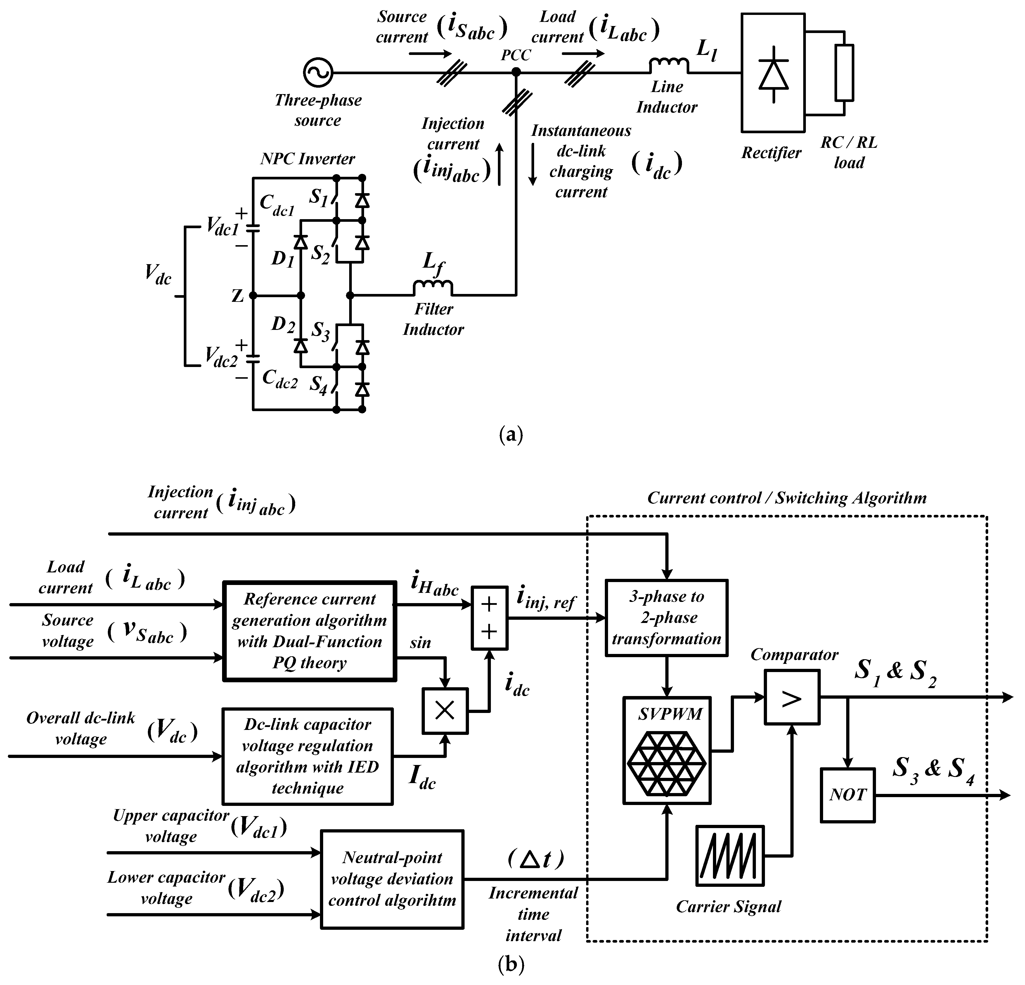
2. Shunt Active Power Filter: Circuit Connection and Control Structure
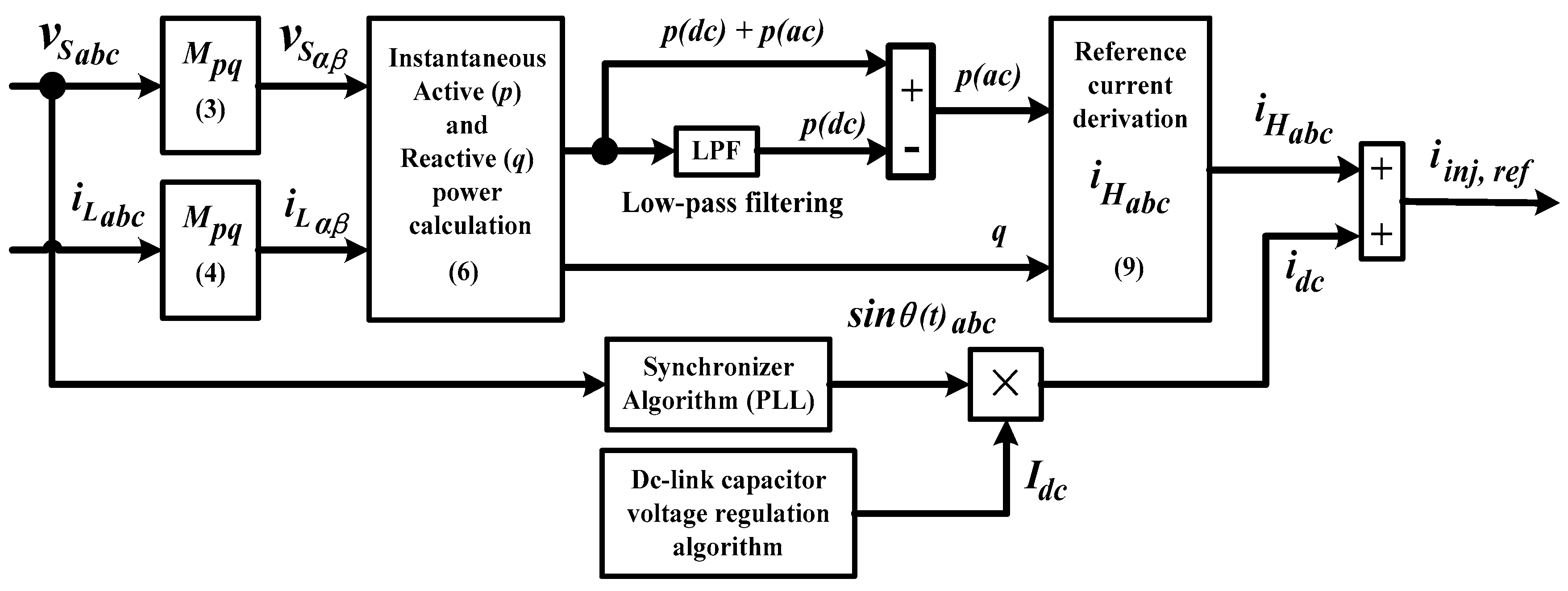
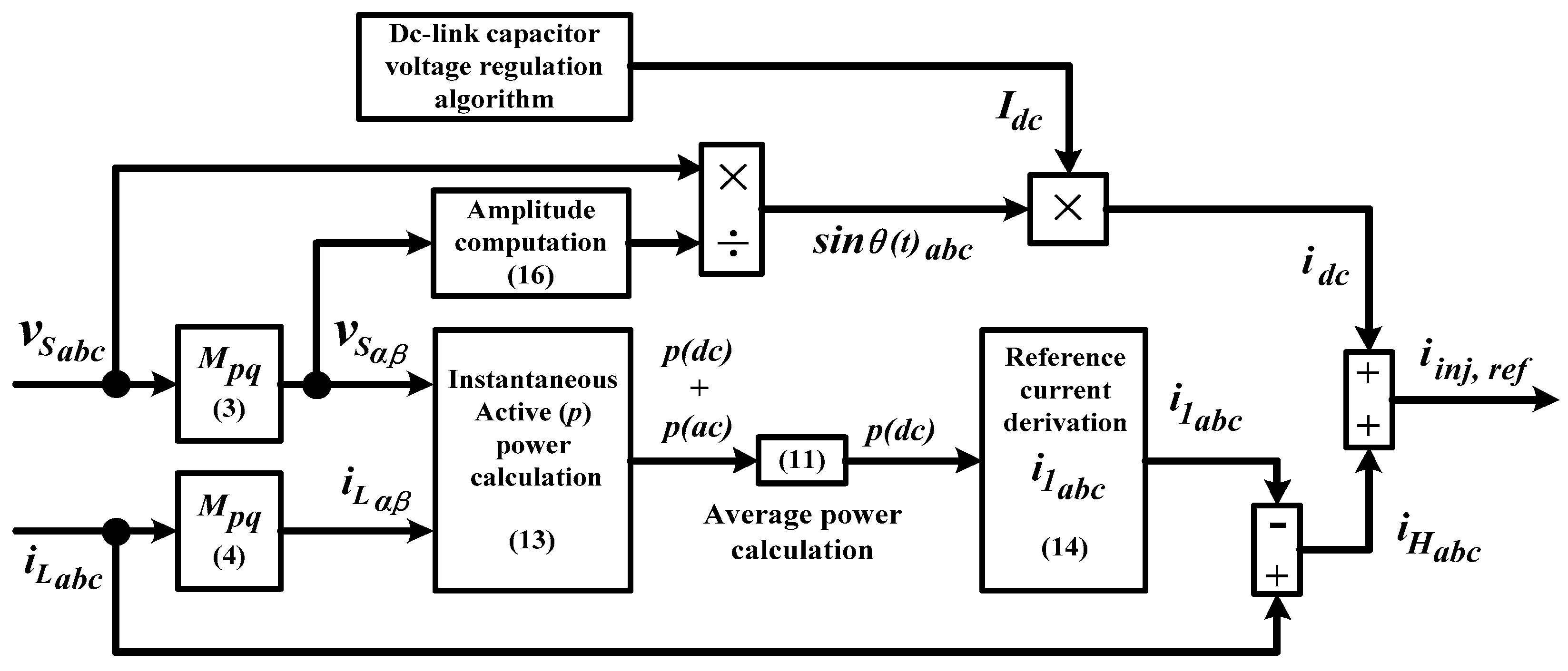
Figure 1 shows circuit connection and control structure of the SAPF. A three-level neutral-point-clamped (NPC) inverter (serving as the SAPF) is connected to the operating power system between power supply and rectifier load at point of common coupling (PCC). The rectifier is further commonly connected to two types of loads: either capacitive (RC) or inductive (RL) loads. As illustrated in Figure 1, a typical SAPF operates by injecting mitigation current (hereinafter referred to as injection current) in opposite phase into the polluted power system via PCC to mitigate the harmonic current and concurrently drawing a certain amount of current (hereinafter referred to as instantaneous dc-link charging current) to regulate its switching losses. In this manner, the harmonic current present in the power system will slowly be removed and eventually the polluted source current will regain its sinusoidal appearance with fundamental frequency.
Meanwhile, its control structure is made up of four control algorithms that work in sync together, i.e., reference current generation, dc-link capacitor voltage regulation, voltage balancing and current control or switching algorithms. First, reference current generation algorithm, as stated in Section 1, is responsible for generating a reference current signal that directs operation of SAPF. Further description on this particular algorithm is provided in Section 3. Secondly, dc-link capacitor voltage regulation algorithm is responsible in regulating and maintaining overall dc-link voltage V d c at suitable level. In this case, inverted error deviation (IED) technique is used [22]. It performs by computing magnitude I d c of the instantaneous dc-link charging current i d c and delivers it to the reference current generation algorithm for further control procedures, so that similar amount of current can be drawn by the SAPF to retain its dc-link voltage level.
Thirdly, voltage balancing algorithm is responsible for keeping a voltage balance across all individual capacitors. In the case when NPC inverter is employed, the algorithm is more commonly referred to as neutral-point voltage deviation control algorithm. Moreover, in the case of three-level NPC inverter (as employed in this work), which consists of two individual capacitors ( V d c 1 and V d c 2 ) at the dc-side, the voltage across each individual capacitor must be equal and maintained at half the value of V d c . For this purpose, dwell time allocation (DTA) technique is applied [23]. It performs by delivering the required incremental time interval Δ T to adjust switching period of each power switch according to degree of voltage difference between V d c 1 and V d c 2 . Note that, voltage balancing is required only when dc-side of the adopted inverter possesses more than one capacitor especially when dealing with multilevel inverter topologies. Fourthly, current control or switching control algorithm is responsible in generating switching pulses S 1 4 to direct operation of the SAPF. In this case, space vector pulse-width modulation (SVPWM) control algorithm that performs at switching frequency of 25 kHz is applied [24].

3. Dual-Function Instantaneous Power p q Theory Algorithm

Control structure and operating principle of the p q theory algorithm applied in this work is provided in this section. To ease the explanation process and clearly present the implemented enhancements, details of the existing p q theory algorithm is first presented. Subsequently, working concept of the proposed dual-function p q theory algorithm is described emphasizing on the differences and implemented modifications.

3.1. The Existing p q Theory Algorithm

Figure 2 shows control structure of the existing p q theory algorithm. Basically, the reference current generation processes involves two consecutive computation processes: (1) a sequence of instantaneous power calculations in a balanced three-phase system to extract harmonic current i H a b c from the polluted power system; and (2) derivation of reference current i i n j , a b c by using the extracted harmonic current and instantaneous dc-link charging current i d c (delivered by dc-link capacitor voltage regulation algorithm). The calculations to extract harmonic current are conducted in α β domain where all the required three-phase a b c signals must first be transformed into their corresponding two-phase α β representation by using a transformation matrix M p q [25,26] which is expressed as:
M p q = 2 3 [ c o s θ 1 ( t ) c o s θ 3 ( t ) c o s θ 2 ( t ) s i n θ 1 ( t ) s i n θ 3 ( t ) s i n θ 2 ( t ) ]
where
θ p h ( t ) = θ ( t ) + 2 π 3 ( p h 1 ) , p h = 1 , 2 , 3
and θ ( t ) is an angular arbitrary function and is considered as θ ( t ) = 0 .
Let the three-phase source voltage and load current expressed in matrix form be v S a b c = [ v S a   v S b   v S c ] T and i L a b c = [ i L a   i L b   i L c ] T , respectively. Hence, their corresponding α β representations can be expressed as
[ v S α v S β ] T = M p q v S a b c
[ i L α i L β ] T = M p q i L a b c
Meanwhile, in α β domain, complex power s can be expressed as
s = p + j q = v S α β i * L α β = ( v S α j v S β ) ( i L α + j i L β ) = ( v S α i L α + v S β i L β ) + j ( v S α i L β v S β i L α )
where p and q symbolize the instantaneous active and reactive power, respectively, and * represents a complex conjugate.
For simplicity, from Equation (5), the computed active and reactive power can be rewritten in a more concise form as
[ p q ] = [ v S α v S β v S β v S α ] [ i L α i L β ] .
Note that, due to contamination of harmonic current, the computed p and q can actually be separated into fundamental ( d c ) and harmonic ( a c ) elements and thus a new relationship of instantaneous power can be formed as
[ p q ] = [ p ( d c ) q ( d c ) ] + [ p ( a c ) q ( a c ) ]
where p ( d c ) and p ( a c ) symbolize the fundamental ( d c ) and harmonic ( a c ) elements of instantaneous active power, respectively. Similar relation applies to reactive power q ( d c ) and q ( a c ) .
According to the existing p q theory algorithm, p ( a c ) and q are the two main parameters needed to extract harmonic current i H a b c . Note that the harmonic element of active power p ( a c ) contains information on the magnitude of the harmonic current. Meanwhile, the reactive power q is mainly responsible in representing the resulted phase difference (due to presence of harmonics) between source voltage and current. The p ( a c ) element is commonly obtained via indirect identification approach [4], i.e., by using a second order Butterworth-type LPF with cutting frequency of 10 Hz [7,18] which can be represented as
p ( a c ) = p L P F ( p ( d c ) + p ( a c ) ) .
Note that, according to this approach, d c element of the active power p ( d c ) is first detected by the LPF and is then subtracted from the actual active power p .
Thereafter, an inverse transformation approach is applied to p ( a c ) or p p ( d c ) and q , to derive the desired harmonic current i H a b c . A compact style of the inverse transformation approach can be expressed as
i H a b c = M p q T d e t ( p q ) [ v S α v S β v S β v S α ] [ p p ( d c ) q ]
where d e t ( p q ) = v S α 2 + v S β 2 .
With availability of i H a b c , the reference current i i n j , r e f can subsequently be acquired according to the following approach:
i i n j , r e f = i H a b c + I d c s i n θ ( t ) a b c
where I d c is the magnitude of instantaneous dc-link charging current i d c (a controlled variable responsible for regulating the overall dc-link voltage V d c of SAPF) obtained by using dc-link capacitor voltage regulation algorithm and s i n θ ( t ) a b c is the synchronization phase delivered by synchronizer algorithm particularly a PLL to ensure proper synchronization of I d c with i H a b c so that i i n j , r e f can precisely be generated. It is important to note that, for the sole purpose of extracting harmonic current i H a b c , the existing p q theory algorithm itself can actually perform without needing any external PLL. However, to effectively generate the desired reference current, there is a need to properly synchronize operation of the reference current generation with the dc-link capacitor voltage regulation algorithms and thus a PLL ought to be applied.

3.2. The Three Proposed Enhancements

By referring to the existing p q theory algorithm shown in Figure 2, three notable enhancements have been implemented to form the proposed dual-function p q theory algorithm, as illustrated in Figure 3. The first enhancement is implemented aimed to overcome two inherent weaknesses of tuned numerical LPF, i.e., the tedious workloads in finding the best match between cutting frequency and filter’s order, and significant delay in detecting fundamental p ( d c ) element. For that purpose, an average power detection method is incorporated and it is expressed as
p ( d c ) = p ( a v e r a g e ) = 1 T 0 T ( p ( d c ) + p ( a c ) ) d t
where T symbolizes period of the active power p signal and p ( a v e r a g e ) is its average value. This approach is possible because in α β rotating frame, d c element of any signal is actually equivalent to its average value. Therefore, by using the incorporated average power detection approach, there is no need for any traditional filtering. In this manner, the possibility of error in detecting d c element due to improper tuning of LPF can be avoided.
Next, the second improvement is implemented to achieve reduction in algorithm complexity. It is achieved by removing the reactive power q which is perceived to be insignificant in the process of generating reference current. For that purpose, operation of the existing p q theory algorithm needs to be changed. Instead of generating i H a b c directly using Equation (9), the proposed algorithm is designed to produce it indirectly, i.e., by first computing the fundamental active current i 1 a b c and then directly subtract it from the load current i L a b c . The indirect approach in generating i H a b c can be expressed as
i H a b c = i L a b c i 1 a b c .
According to the indirect approach, the computed p ( d c ) is first utilized to generate i 1 a b c without going through the calculation process of Equation (8). The fundamental active current i 1 a b c is expected to be a purely sinusoidal signal (contain only sine element) with fundamental frequency and phase similar to that of source voltage. With this expectation, reactive power q which represents the phase difference between source voltage and current (as described previously in Section 3.1), is no longer needed in the computation process. This simply means that using only active power p is good enough to represent the sinusoidal characteristic and in phase operation (with source voltage) of the resulted fundamental active current i 1 a b c . After removing the insignificant reactive power q , instantaneous power calculation approach expressed previously as Equation (6) can therefore be simplified as Equation (13).
p = [ v S α v S β ] [ i L α i L β ]
i 1 a b c = M p q T p ( d c ) d e t ( p q ) [ v S α v S β ]
On the other hand, the concise inverse transformation approach expressed previously as Equation (9) can now be simplified as Equation (14) to transform the detected p ( d c ) back into actual three-phase fundamental active current i 1 a b c for derivation of reference current. Subsequently, the reference current i i n j , r e f is obtained using Equation (10).
Thirdly, the enhancement is made to eliminate reliance on PLL element which requires series of complex calculation processes in tracking the required phase information s i n θ ( t ) a b c from source voltage v S a b c . For that purpose, a phase tracking technique is integrated allowing the proposed algorithm to produce its own synchronization phase. The integrated phase tracking technique makes good use of natural characteristic of the p q theory algorithm to transform the three-phase source voltage v S a b c into s i n θ ( t ) a b c for synchronization purposes. It is accomplished according to two consecutive processes listed below:
(1)
Compute magnitude V m a g of v S a b c based on the values of v S α and v S β which is obtained using Equation (3).
(2)
Divide v S a b c directly with the generated magnitude V m a g .
Since generation of v S α and v S β is originally part of the operational stages in p q theory algorithm, hence the phase tracking technique can be integrated into the p q theory algorithm with minimal efforts. Operation of the proposed technique can effectively be simplified into a concise form as follow:
s i n θ ( t ) a b c = v S a b c V m a g
where
V m a g = 2 3 d e t ( p q ) .
By referring to Equation (15), it is important to note that the generated sine function s i n θ ( t ) a b c is actually unity (magnitude) representation of v S a b c . Since s i n θ ( t ) a b c is directly generated by processing the three-phase source voltage, it can be stated that s i n θ ( t ) a b c is in accordance with the phase of source voltage. The generated s i n θ ( t ) a b c is then used to synchronize I d c with i H a b c (obtained from Equation (12)) according to Equation (10), thus producing the desired reference current i i n j , r e f . With incorporation of Equation (15), the proposed p q theory algorithm can now be used for generating reference current and synchronization purposes, and therefore dual functionality.

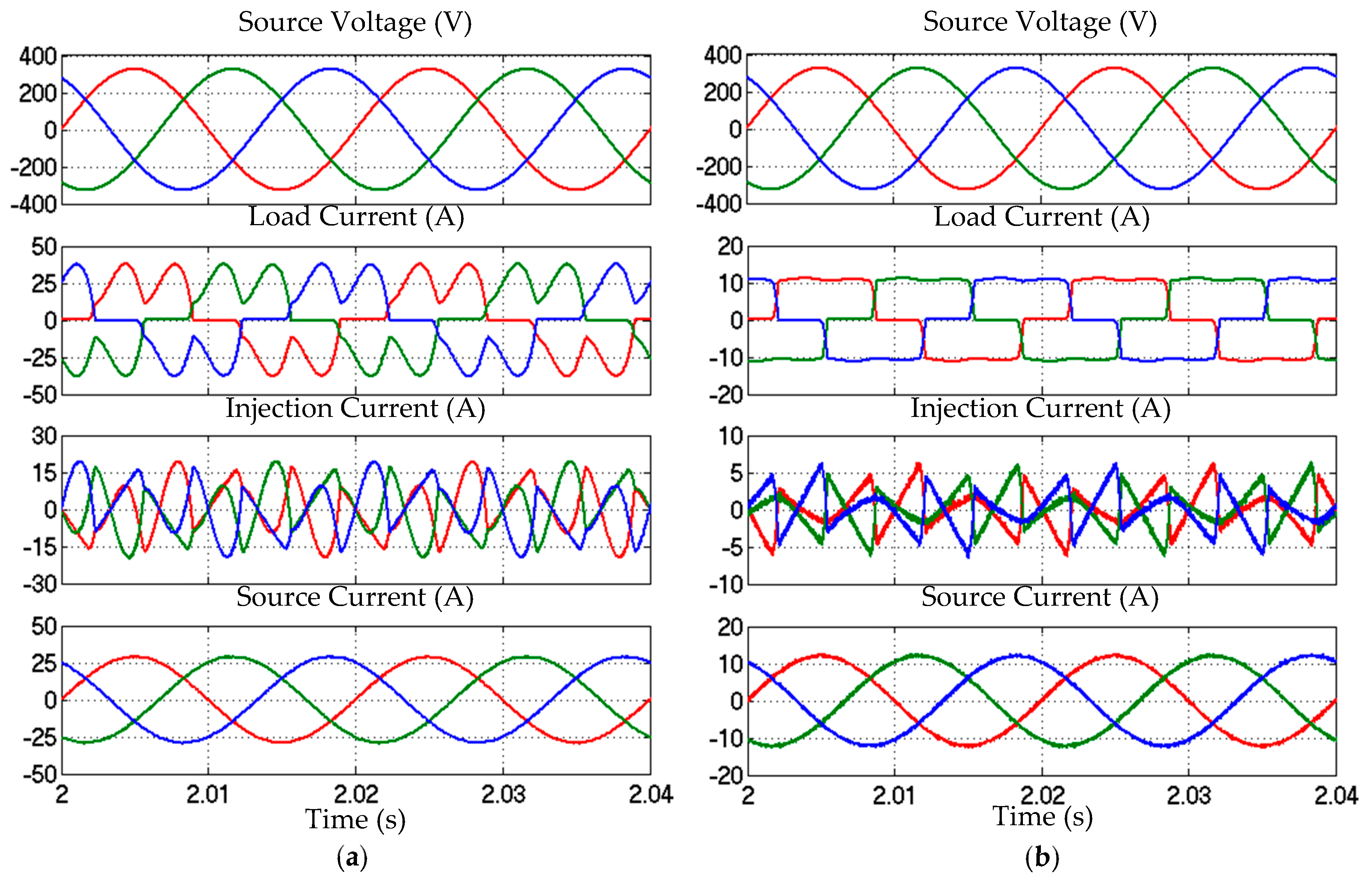
4. Simulation Results

Simulation work which included development of SAPF circuits, its control algorithms, and assessment of the proposed dual-function p q theory algorithm was conducted in MATLAB-Simulink platform (R2012a). Simple Simulink-blocks were used to design all the SAPF circuits and control algorithms, and the simulation was executed in discrete environment. Steady-state and dynamic-state simulation studies were conducted, considering balanced-sinusoidal source voltage (400 Vrms, 50 Hz). Meanwhile, the dc-link capacitors applied were 3300 μF (each), with reference overall dc-link voltage set to be 880 V (440 V for each individual capacitor). Next, a simple L -typed filter (5 mH inductor) was applied as the output filter of SAPF. The function of an output filter is to minimize switching ripples generated by SAPF during its operation. In this work, a L -typed filter was considered rather than other types such as L C -typed and L C L -typed filters, as it is the least complex among the filters and thus reduces complexity of the overall SAPF structure. Furthermore, for the sources of harmonics, two types of nonlinear loads were considered. The first nonlinear load comprised an uncontrolled bridge rectifier that is further connected (in parallel) to a 20 Ω resistor and 2200 μF capacitor (hereinafter referred to as capacitive load). The second nonlinear load comprised a similar uncontrolled bridge rectifier that is further connected (in series) to a 50 Ω resistor and 50 mH inductor (hereinafter referred to as inductive load). Analysis was performed in comparative manner, i.e., by benchmarking performance of SAPF while applying the proposed dual-function p q theory algorithm, with the one using the existing p q theory algorithm.
For steady-state analysis, performance of the proposed algorithm was analyzed based on degree of ripples retained in the detected fundamental ( d c ) element of active power and ability of SAPF to maintain THD value of source current (after mitigation) below 5% limit as stated in IEEE Standard 519-2014 [27]. The degree of retained ripples was measured in terms of percentage by using a key parameter known as percentage of ripple power % p ( r i p p l e ) which is defined as
% p ( r i p p l e ) = p ( d c ) , p p p ( d c ) , d e s i r e d × 100 %
where p ( d c ) , p p and p ( d c ) , d e s i r e d symbolize peak-to-peak and the desired fundamental ( d c ) element of active power, respectively.
On the other hand, for dynamic-state analysis, its performance is judged based on its dynamic responses in detecting the desired d c element of active power, i.e., by observing the demonstrated overshoot or undershoot, and response time. Subsequently, the time taken by SAPF to effectively mitigate harmonic current was also recorded for performance judgment. For this analysis, the connected nonlinear load was switched from capacitive to inductive to form a dynamic-state condition.

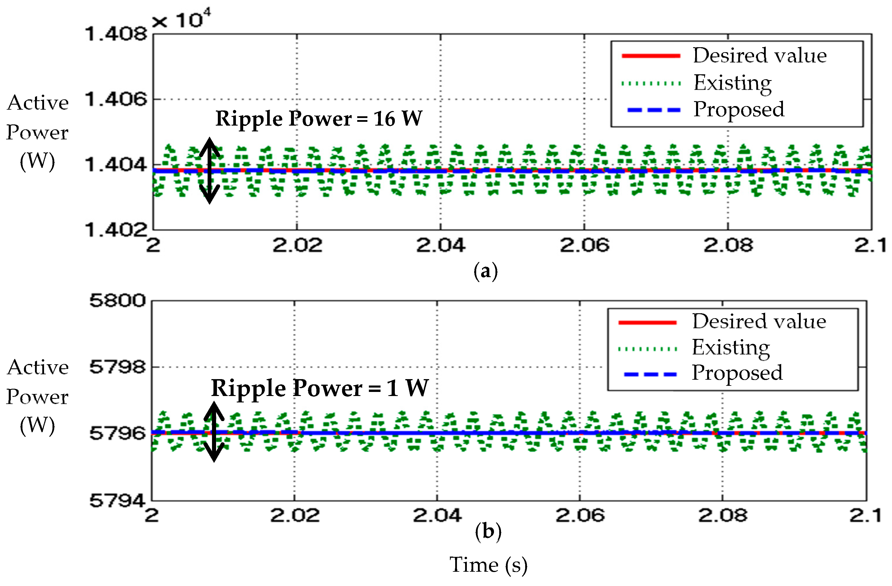
4.1. Steady-State Condition Analysis

Figure 4 provides the simulation result that shows the performance of each reference current generation algorithm in detecting the desired fundamental element of active power p ( d c ) for capacitive and inductive loads. As can be observed in Figure 4, both proposed and existing p q theory algorithms are able to detect the desired p ( d c ) effectively, but there is a huge difference in terms of % p ( r i p p l e ) between the detected p ( d c ) . For both nonlinear loads, p ( d c ) detected by the proposed algorithm is free from any ripples. In contrast, significant ripple power of 16 W ( % p ( r i p p l e ) = 0.11%) and 1 W ( % p ( r i p p l e ) = 0.02%) are revealed to retain in the p ( d c ) detected by the existing algorithm for capacitive and inductive loads, respectively. Hence, in terms of the ability to detect the desired p ( d c ) , the average power detector which has been integrated in the proposed algorithm is able to perform with higher accuracy as compared to the numerical LPF applied in the existing algorithm.
On the other hand, Figure 5 provides simulation result that shows the steady-state simulation waveforms of three-phase source voltage v S a b c , load current i L a b c , injection current i i n j a b c , and source current i S a b c , demonstrated by SAPF while applying the proposed algorithm, for capacitive and inductive loads. Meanwhile, all the resulted THD values of source current after mitigation by SAPF while applying its respective reference current generation algorithm are tabulated in Table 1. Both algorithms effectively direct their respective SAPF in maintaining THD values of source current below the allowable limit. However, SAPF which is controlled by the proposed algorithm shows superior effectiveness in mitigating harmonic current, i.e., by achieving lower THD values for both capacitive and inductive loads, as compared to the SAPF which is controlled by the existing algorithm. The THD values recorded while applying the proposed algorithm is 0.06–0.09% (capacitive) and 0.11–0.12% (inductive) lower than that obtained while applying the existing algorithm. Furthermore, it also can clearly be observed from Figure 5 that the mitigated source current (all three-phases) is working in phase with the source voltage for both nonlinear loads which leads to maximum power factor.
Hence, from the conducted steady-state analysis, the existing p q theory algorithm is unable to provide a “ripple free” p ( d c ) detection. The ripples retained in the detected p ( d c ) have degraded quality of the generated reference current. Therefore, performance of SAPF in mitigating harmonic current is observed to have been degraded (indicated by higher THD value). However, by applying the proposed dual-function p q theory algorithm which can provide ripples-free detection of p ( d c ) , an accurate reference current can be generated to effectively control operation of SAPF, and thus improving its mitigation performance (indicated by lower THD value). This is the main factor contributing to superior mitigation performance (in terms of the resulted THD value) of SAPF that applies the proposed algorithm over the SAPF that applies the existing algorithm.

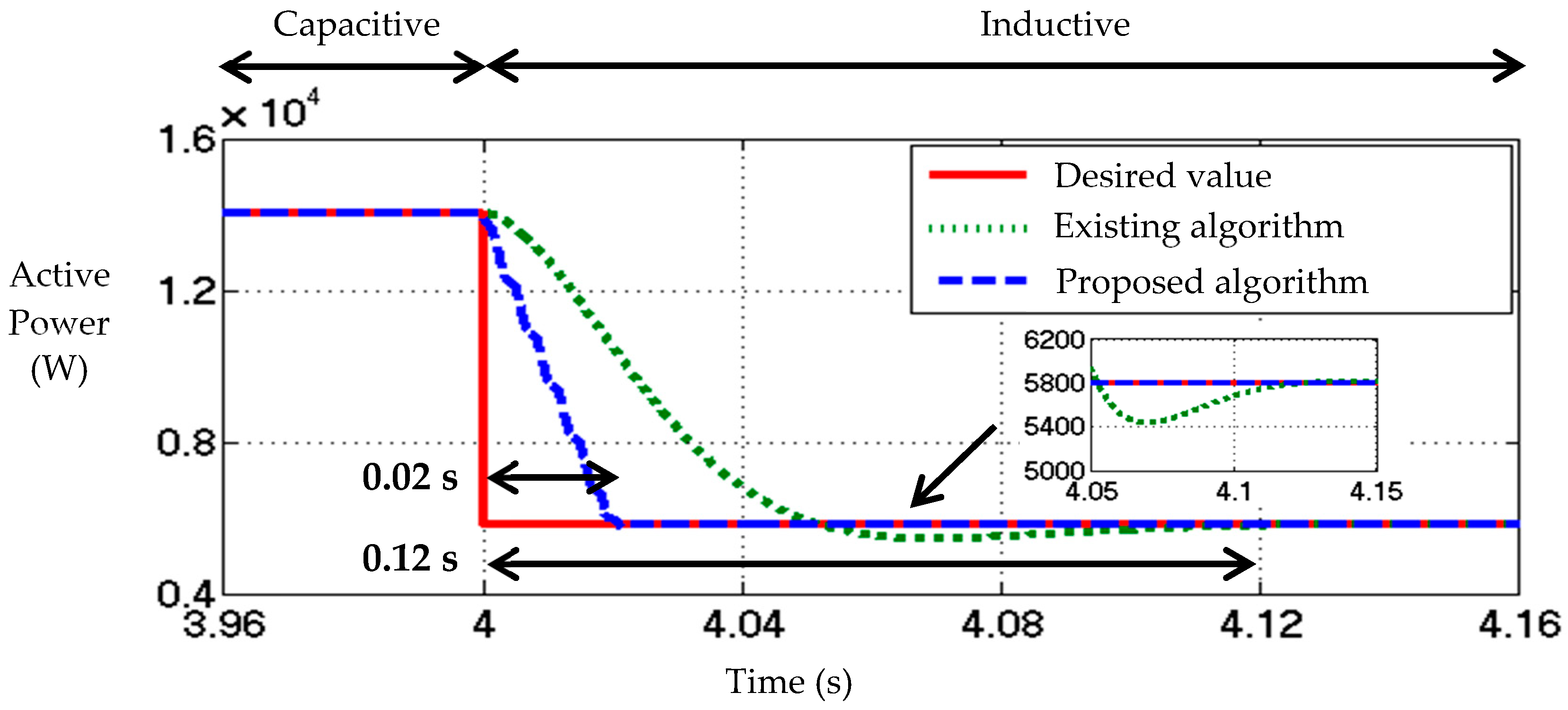
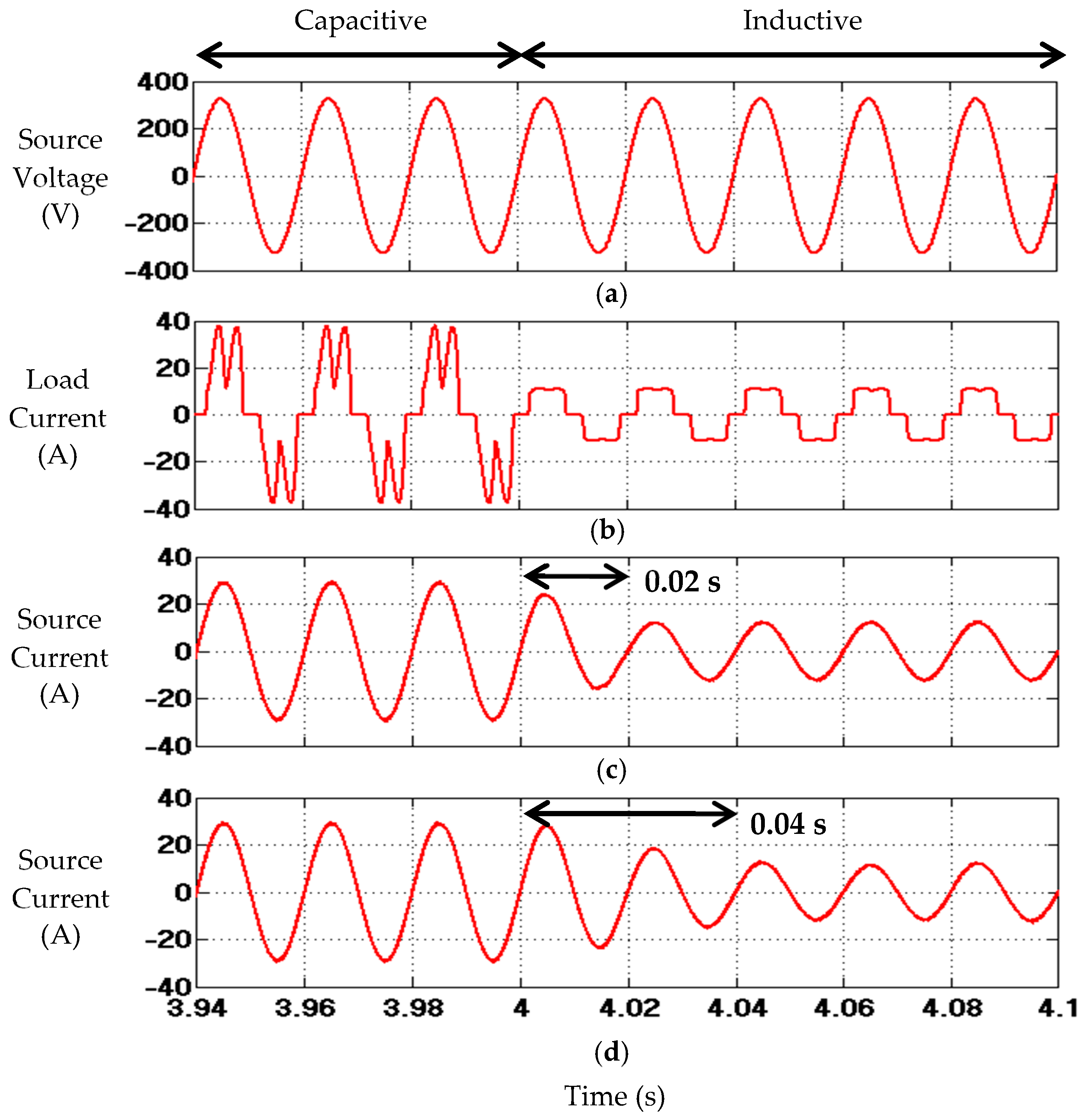
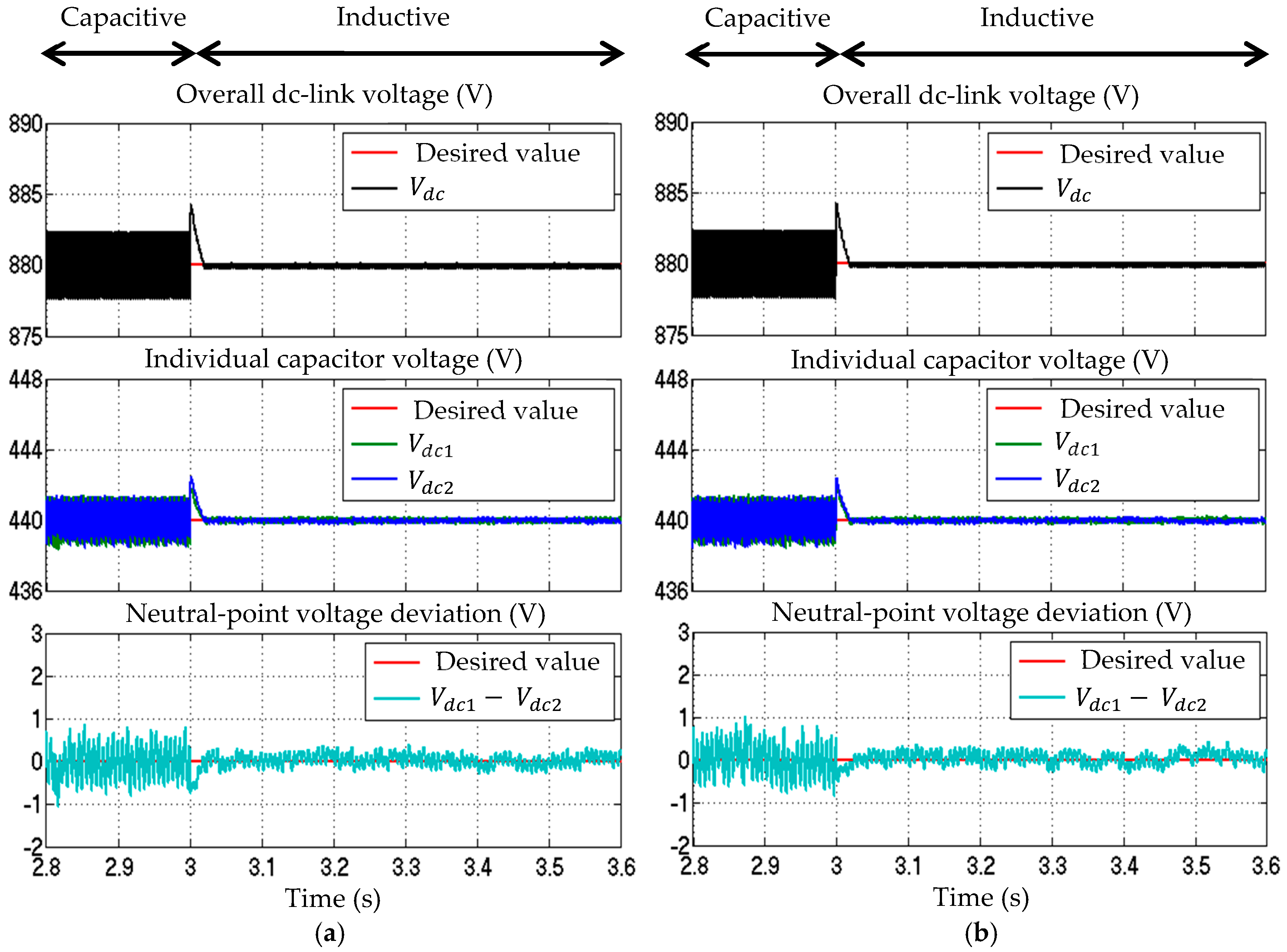
4.2. Dynamic-State Condition Analysis

Simulation result showing dynamic responses of each reference current generation algorithm in detecting the desired p ( d c ) , is provided in Figure 6. From the findings, when the nonlinear load changes from capacitive to inductive (at time = 4 s), the proposed algorithm is observed to perform outstandingly with fast response time of 0.02 s and without any notable undershoots. However, the existing algorithm is found to perform poorly with large response time of 0.12 s and significant undershoots of 400 W. In other words, in terms of the ability to detect p ( d c ) , the proposed algorithm outperforms the existing algorithm by achieving a response time of 6 times faster.
On the other hand, simulation result that shows dynamic responses of SAPF in mitigating harmonic current is provided in Figure 7. From the findings, when the nonlinear load changes from capacitive to inductive (at time = 4 s), SAPF which is controlled by the proposed algorithm is observed to perform outstandingly with fast response time of 0.02 s. Meanwhile, SAPF which is controlled by the existing algorithm is observed to perform poorly with slower response time of 0.04 s. In other words, in terms of the ability to mitigate harmonic current, by utilizing the proposed algorithm, SAPF can achieve a response time that is two times faster.
Hence, based on the findings obtained from dynamic-state analysis, the unique ability of the proposed algorithm in providing fast p ( d c ) detection has greatly enhanced dynamic response of SAPF in mitigating harmonic current. With fast p ( d c ) detection, the required reference current needed to control operation of SAPF can be generated at an earlier pace and thus achieving effective harmonic current mitigation with faster response time (as revealed in Figure 7). This is the main factor that contributes to superior mitigation performance (in term of the demonstrated response time) of SAPF that applies the proposed algorithm over the SAPF that applies the existing algorithm.
Other than mitigation performance, it is also important to assess behavior of dc-link voltages to ensure effective operation of SAPF. Figure 8 provides the related result. From the findings, SAPF utilizing each reference current generation algorithm is observed to function effectively where all its respective dc-link voltages are effectively regulated and continuously kept at the desired value. Concurrently, voltages across the two individual dc-link capacitors ( V d c 1 and V d c 2 ) are likewise found to be effectively regulated and are evenly balanced at half the value of overall dc-link voltage V d c with minimal neutral-point voltage deviation. Besides, by comparing the behavior of dc-link voltages demonstrated by SAPF while using the proposed algorithm (as shown in Figure 8a) and SAPF while using the existing algorithm (as shown in Figure 8b), no significant differences can be observed. In other words, utilization of the proposed algorithm actually does not show significant impact towards the performance of dc-link voltages. This is another interesting feature of the proposed algorithm which makes it worth implementing.

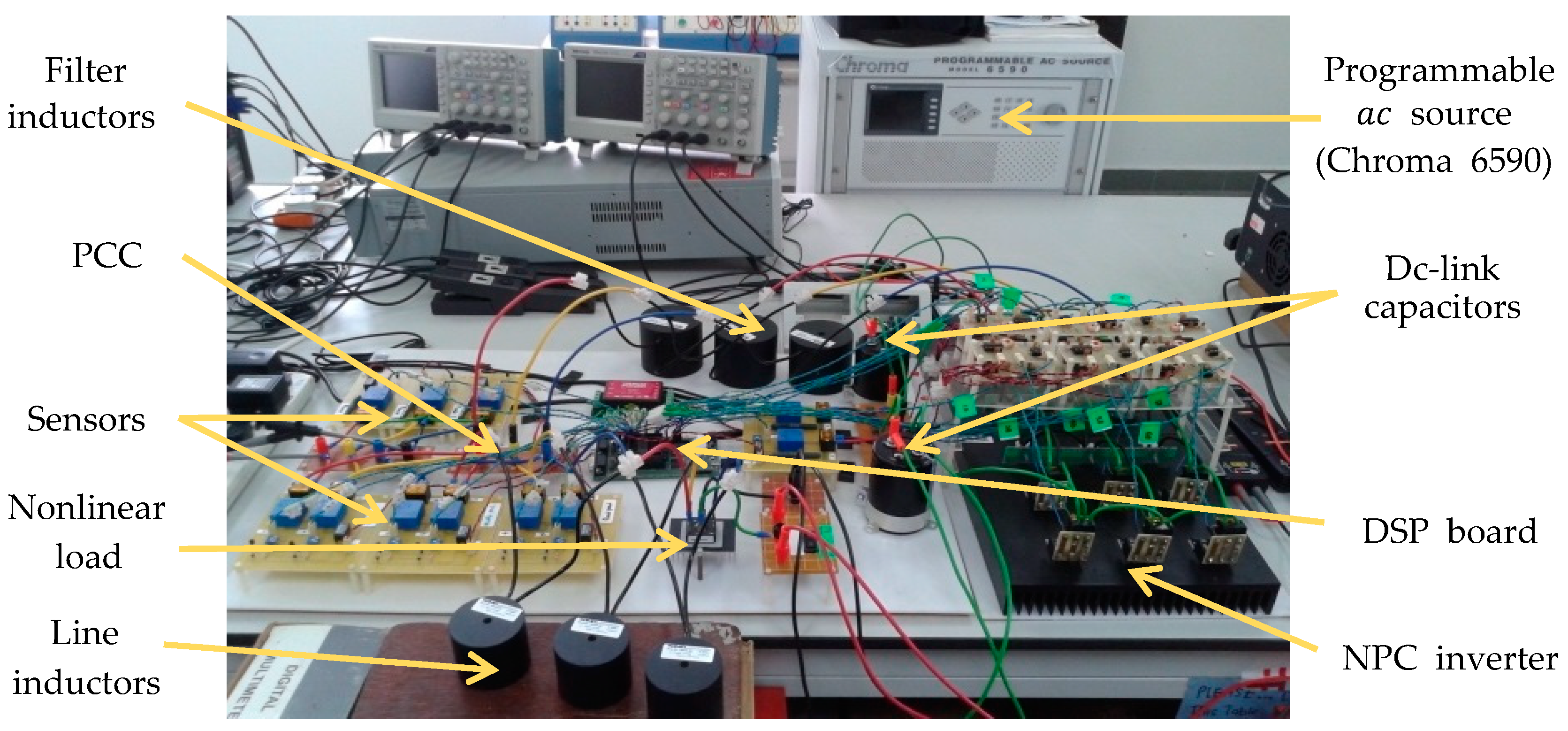
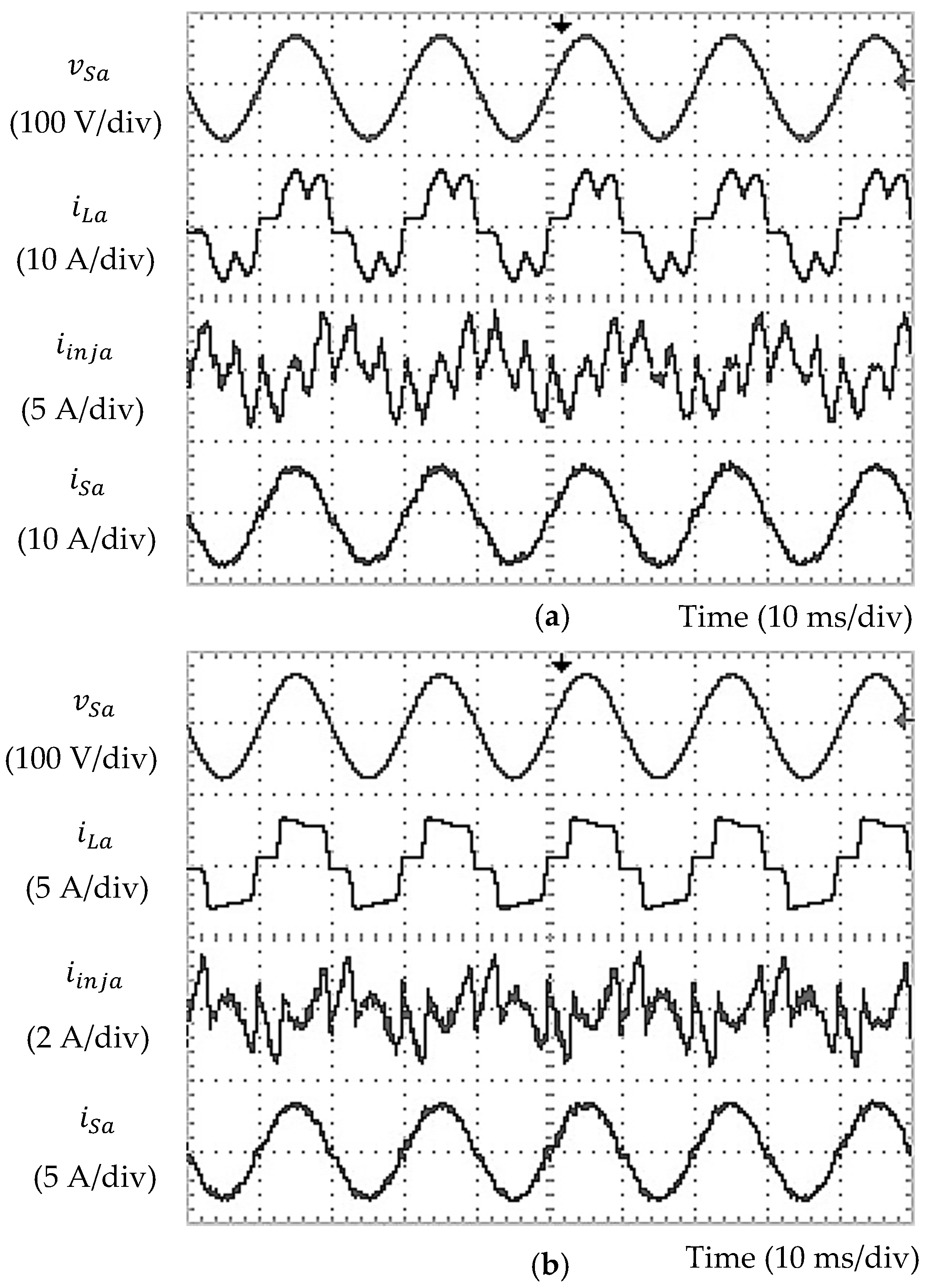
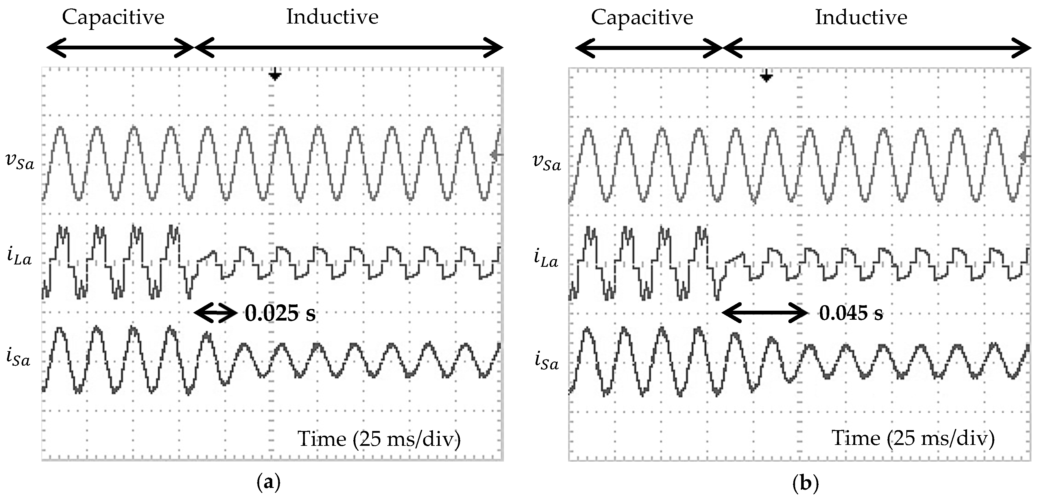
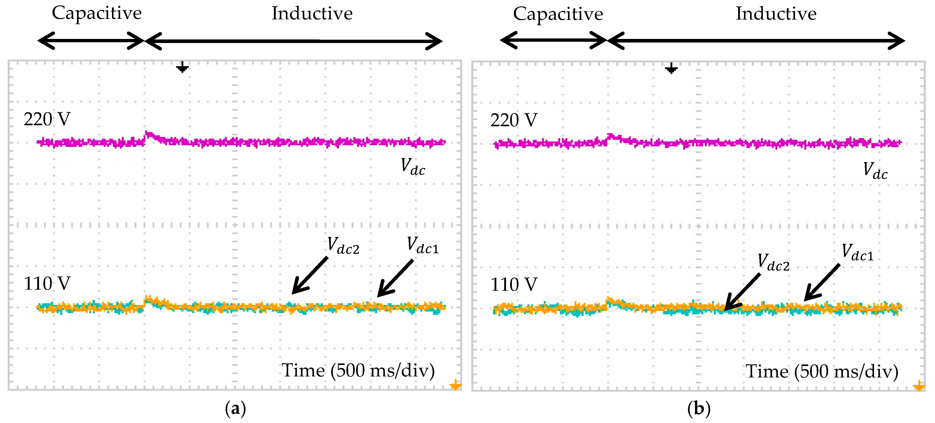
5. Experimental Verification

For experimental verification, power electronic circuits were assembled to form the SAPF and, meanwhile, all the control algorithms were downloaded to a TMS320F28335 digital signal processor (DSP) board via Code Composer Studio (CCS) v3.3 which served as the controller. The constructed experimental prototype is shown in Figure 9. In this case, a balanced-sinusoidal source voltage (100 Vrms, 50 Hz) was applied. It was supplied from a Chroma 6590 programmable a c source. Next, the reference overall dc-link voltage was scaled down to 220 V (110 V for each individual capacitor). Similar to the simulation work, performance of each reference current generation algorithm as also tested and assessed under both steady-state and dynamic-state conditions.
Figure 10 provides experimental result that shows steady-state waveforms of phase a source voltage v S a , load current i L a , injection current i i n j a , and source current i S a , demonstrated by SAPF while applying the proposed algorithm, for capacitive and inductive loads. Meanwhile, all the resulted THD values of source current after mitigation by SAPF while applying its respective reference current generation algorithm are tabulated in Table 2. On the other hand, experimental result that shows dynamic responses of SAPF in mitigating harmonic current is provided in Figure 11.
Based on the experimental findings, both algorithms perform effectively in directing their respective SAPF to remove the generated harmonic current. As a result, all the recorded THD values of source current are below the 5% limit, for both capacitive and inductive loads. However, THD values recorded for the case when the proposed algorithm is being applied (as tabulated in Table 2) is in a lower range, i.e., within 2.98–3.33% as compared to that recorded for the case when the existing algorithm is being applied where it performs within a higher range of 3.83–4.16%. This confirms the benefits of applying the proposed algorithm instead of using the existing algorithm under steady-state conditions. Moreover, as can be observed in Figure 10, phase a source current i S a seems to work in phase with phase a source voltage v S a for both nonlinear loads, hence almost unity power factor can be obtained. Most importantly, as clearly shown in Figure 11, under dynamic-state condition, SAPF which is controlled by the proposed algorithm can perform effectively in mitigating harmonic current with a faster response time of 0.025 s. However, SAPF which is controlled by the existing algorithm demonstrates a slower response time of 0.045 s. This confirms the benefits of applying the proposed algorithm instead of using the existing algorithm under dynamic-state conditions.
Furthermore, Figure 12 provides experimental result that shows performance of SAPF while applying each reference current algorithm in terms of dc-link voltages regulation. From the findings, it can be confirmed that SAPF with each reference current generation algorithm is observed to function effectively where all its respective dc-link voltages are properly regulated and continuously kept at the desired value. At the same time, voltages across the two individual dc-link capacitors ( V d c 1 and V d c 2 ) are likewise found to be effectively regulated and are evenly balanced at half the value of overall dc-link voltage V d c . Besides, by comparing Figure 12a,b, it can be observed that the behavior of dc-link voltages demonstrated by SAPF while utilizing the proposed algorithm (as shown in Figure 12a) and that demonstrated by SAPF while utilizing the existing algorithm (as shown in Figure 12b) is actually quite similar. In other words, it can also be confirmed that utilization of the proposed algorithm does not show significant impact towards performance of SAPF in term of dc-link voltages control.
Overall, as reported by the simulation and experimental results, design concept of the proposed dual-function p q theory algorithm itself and subsequently its operation with the other algorithms in the control system of SAPF can be confirmed to be valid and correct. By utilizing the proposed dual-function p q theory algorithm, mitigation performance of SAPF can be improved in terms of the resulted THD values and dynamic responses.

6. Conclusions

This paper has successfully demonstrated a dual-function p q theory algorithm which is able to generate reference current and simultaneously provides synchronization phase to ensure effective operation of SAPF, without relying on PLL element. Three notable improvements are implemented: replacement of numerical low-pass filter (LPF) with an average power detector to improve mitigation performance, removal of needless reactive element to reduce algorithm complexity and integration of phase tracking feature to eliminate the needs of PLL. Design concept and effectiveness of the proposed algorithm is thoroughly analyzed under steady-state and dynamic-state conditions. It is revealed from the simulation work that the proposed algorithm effectively eliminates ripples that are retained in the detected fundamental element and subsequently directs the SAPF in mitigating harmonic current with a lower THD value. Moreover, under dynamic-state condition, by applying the proposed algorithm, SAPF can perform with fast response time and without any undershoots. Effectiveness of the proposed algorithm is further supported and validated by experimental analysis. Overall, the low THD value of mitigated source current and fast response time in mitigating harmonic current are the key benefits of applying the proposed algorithm over the existing algorithm.

Author Contributions

Y.H. designed and developed the simulation model, experimental prototype, and performed all the tests and analyses for the research work. Y.H. was also mainly responsible for preparing the initial draft of the manuscript. M.A.M.R. actively contributed to the simulation and experimental works, and manuscript improvement. M.K.H. and N.F.M. contributed to verifying the work and finalizing the manuscript.

Conflicts of Interest

The authors declare no potential conflict of interest.

References

  1. Choi, W.-H.; Lam, C.-S.; Wong, M.-C.; Han, Y.-D. Analysis of dc-link voltage controls in three-phase four-wire hybrid active power filters. IEEE Trans. Power Electron. 2013, 28, 2180–2191. [Google Scholar] [CrossRef]
  2. Kale, M.; Ozdemir, E. An adaptive hysteresis band current controller for shunt active power filter. Electr. Power Syst. Res. 2005, 73, 113–119. [Google Scholar] [CrossRef]
  3. Akagi, H. Active harmonic filters. Proc. IEEE 2005, 93, 2128–2141. [Google Scholar] [CrossRef]
  4. Green, T.C.; Marks, J.H. Control techniques for active power filters. IEE Proc. Electr. Power Appl. 2005, 152, 369–381. [Google Scholar] [CrossRef]
  5. Asiminoaei, L.; Blaabjerg, F.; Hansen, S. Detection is key-harmonic detection methods for active power filter applications. IEEE Ind. Appl. Mag. 2007, 13, 22–33. [Google Scholar] [CrossRef]
  6. Chudamani, R.; Vasudevan, K.; Ramalingam, C.S. Non-linear least-squares-based harmonic estimation algorithm for a shunt active power filter. IET Power Electron. 2009, 2, 134–146. [Google Scholar] [CrossRef]
  7. Eskandarian, N.; Beromi, Y.A.; Farhangi, S. Improvement of dynamic behavior of shunt active power filter using fuzzy instantaneous power theory. J. Power Electron. 2014, 14, 1303–1313. [Google Scholar] [CrossRef]
  8. Wang, L.; Lam, C.-S.; Wong, M.-C. Unbalanced control strategy for a thyristor-controlled LC-coupling hybrid active power filter in three-phase three-wire systems. IEEE Trans. Power Electron. 2017, 32, 1056–1069. [Google Scholar] [CrossRef]
  9. Popescu, M.; Bitoleanu, A.; Suru, V. A DSP-based implementation of the p-q theory in active power filtering under nonideal voltage conditions. IEEE Trans. Ind. Inform. 2013, 9, 880–889. [Google Scholar] [CrossRef]
  10. Pigazo, A.; Moreno, V.M.; Estebanez, E.J. A recursive park transformation to improve the performance of synchronous reference frame controllers in shunt active power filters. IEEE Trans. Ind. Electron. 2009, 24, 2065–2075. [Google Scholar] [CrossRef]
  11. Monfared, M.; Golestan, S.; Guerrero, J.M. A new synchronous reference frame-based method for single-phase shunt active power filters. J. Power Electron. 2013, 13, 692–700. [Google Scholar] [CrossRef]
  12. Musa, S.; Radzi, M.A.M.; Hizam, H.; Wahab, N.I.A.; Hoon, Y.; Zainuri, M.A.A.M. Modified synchronous reference frame based shunt active power filter with fuzzy logic control pulse width modulation inverter. Energies 2017, 10, 758. [Google Scholar] [CrossRef]
  13. Vodyakho, O.; Mi, C.C. Three-level inverter-based shunt active power filter in three-phase three-wire and four-wire systems. IEEE Trans. Power Electron. 2009, 24, 1350–1363. [Google Scholar] [CrossRef]
  14. Sujitjorn, S.; Areerak, K.-L.; Kulworawanichpong, T. The dq axis with Fourier (dqF) method for harmonic identification. IEEE Trans. Power Deliv. 2007, 22, 737–739. [Google Scholar] [CrossRef]
  15. Bhattacharya, A.; Chakraborty, C. A shunt active power filter with enhanced performance using ANN-based predictive and adaptive controllers. IEEE Trans. Ind. Electron. 2011, 58, 421–428. [Google Scholar] [CrossRef]
  16. Abdeslam, D.O.; Wira, P.; Merckle, J.; Flieller, D.; Chapuis, Y.-A. A unified artificial neural network architecture for active power filters. IEEE Trans. Ind. Electron. 2007, 54, 61–76. [Google Scholar] [CrossRef]
  17. Wang, H.; Li, Q.; Wu, M. Investigation on a new algorithm for instantaneous reactive and harmonic currents detection applied to intensive nonlinear loads. IEEE Trans. Power Deliv. 2007, 22, 2312–2318. [Google Scholar] [CrossRef]
  18. Ng, C.H.; Busawon, K.; Putrus, G.A.; Ran, L. Fast-individual-harmonic-extraction technique. IEE Proc. Gener. Transm. Distrib. 2005, 152, 556–562. [Google Scholar] [CrossRef]
  19. Rodriguez, P.; Pou, J.; Bergas, J.; Candela, J.I.; Burgos, R.P.; Boroyevich, D. Decoupled double synchronous reference frame PLL for power converters control. IEEE Trans. Power Electron. 2007, 22, 584–592. [Google Scholar] [CrossRef]
  20. Campanhol, L.B.G.; Silva, S.A.O.; Goedtel, A. Application of shunt active power filter for harmonic reduction and reactive power compensation in three-phase four-wire systems. IET Power Electron. 2014, 7, 2825–2836. [Google Scholar] [CrossRef]
  21. Mailah, N.F.; Hoon, Y.; Radzi, M.A.M. Dc-link capacitor voltage regulation with effort-reduction fuzzy logic control for three-level inverter-based shunt active power filter. Pertanika J. Sci. Technol. 2017, 25, 11–20. [Google Scholar]
  22. Hoon, Y.; Radzi, M.A.M.; Hassan, M.K.; Mailah, N.F. Dc-link capacitor voltage regulation for three-phase three-level inverter-based shunt active power filter with inverted error deviation control. Energies 2016, 9, 533. [Google Scholar] [CrossRef]
  23. Hoon, Y.; Radzi, M.A.M.; Hassan, M.K.; Mailah, N.F. A simple neutral-point voltage deviation minimization method for three-level inverter-based shunt active power filter. Int. J. Simul. Syst. Sci. Technol. 2016, 17, 33.31–33.36. [Google Scholar]
  24. Bhalodi, K.H.; Agarwal, P. Space vector modulation with dc-link voltage balancing control for three-level inverters. ACEEE Int. J. Commun. 2010, 1, 14–18. [Google Scholar]
  25. Leva, S.; Morando, A.P.; Zaninelli, D. Evaluation of line voltage drop in presence of unbalance, harmonics, and interharmonics: Theory and applications. IEEE Trans. Power Deliv. 2005, 20, 390–396. [Google Scholar]
  26. Herrera, R.S.; Salmeron, P.; Kim, H. Instantaneous reactive power theory applied to active power filter compensation: Different approaches, assessment, and experimental results. IEEE Trans. Ind. Electron. 2008, 55, 184–196. [Google Scholar] [CrossRef]
  27. IEEE Power and Energy Society. IEEE Standard 519, IEEE Recommended Practice and Requirement for Harmonic Control in Electric Power Systems; Institute of Electrical and Electronics Engineers, Inc.: New York, NY, USA, 2014. [Google Scholar]
Figure 1. Three-level NPC inverter working as SAPF: (a) circuit connection; and (b) control algorithms.
Energies 11 01592 g001
Figure 2. Control structure of reference current generation algorithm based on the existing p q theory.
Energies 11 01592 g002
Figure 3. Control structure of reference current generation algorithm based on the proposed dual-function p q theory.
Energies 11 01592 g003
Figure 4. Fundamental element of active power p ( d c ) detected by each reference current generation algorithm for: (a) capacitive load; and (b) inductive load.
Energies 11 01592 g004
Figure 5. Simulation result showing the three-phase source voltage v S a b c , load current i L a b c , injection current i i n j a b c , and source current i S a b c , demonstrated by SAPF utilizing the proposed dual-function p q theory algorithm for: (a) capacitive load; and (b) inductive load.
Energies 11 01592 g005
Figure 6. Fundamental element of active power p ( d c ) detected by each reference current generation algorithm, for dynamic-state condition of capacitive to inductive loads.
Energies 11 01592 g006
Figure 7. Simulation result showing: (a) phase a source voltage v S a ; (b) phase a load current i L a ; (c) phase a source current i S a demonstrated by SAPF while applying the proposed algorithm; and (d) phase a source current i S a demonstrated by SAPF while applying the existing algorithm, for dynamic-state condition of capacitive to inductive loads.
Energies 11 01592 g007
Figure 8. Simulation result showing the overall dc-link voltage V d c , individual capacitor voltages V d c 1 and V d c 2 , and neutral-point voltage deviation ( V d c 1 V d c 2 ) , demonstrated by SAPF while applying: (a) the proposed algorithm; and (b) the existing algorithm, for dynamic-state condition of capacitive to inductive loads.
Energies 11 01592 g008
Figure 9. Laboratory prototype developed to validate design concept and performance of the proposed dual-function p q theory algorithm.
Energies 11 01592 g009
Figure 10. Experimental result showing phase a source voltage v S a ,   phase a load current i L a , phase a injection current i i n j a and phase a source current i S a , demonstrated by SAPF while applying the proposed dual-function p q theory algorithm for: (a) capacitive load; and (b) inductive load.
Energies 11 01592 g010
Figure 11. Experimental result showing phase a source voltage v S a (100 V/div), phase a load current i L a (10 A/div) and phase a source current i S a (10 A/div), demonstrated by SAPF while applying: (a) the proposed algorithm; and (b) the existing algorithm, for dynamic-state condition of capacitive to inductive loads.
Energies 11 01592 g011
Figure 12. Experimental result showing the overall dc-link voltage V d c (20 V/div) and individual capacitor voltages V d c 1 (10 V/div) and V d c 2 (10 V/div), demonstrated by SAPF while applying: (a) the proposed algorithm; and (b) the existing algorithm, for dynamic-state condition of capacitive to inductive loads.
Energies 11 01592 g012
Table 1. Simulation result showing THD values of source current demonstrated by SAPF while applying its respective reference current generation algorithm, for capacitive and inductive loads.
Reference Current Generation AlgorithmTotal Harmonic Distortion, THD (%)
Phase a Phase b Phase c
CapacitiveInductiveCapacitiveInductiveCapacitiveInductive
Without Installation of SAPF
N/A43.0327.3443.0327.3443.0327.34
With Installation of SAPF
dual-function p q theory1.081.721.091.701.091.72
Existing p q theory 1.171.831.151.821.161.84
Table 2. Experimental result showing THD values of source current demonstrated by SAPF while applying its respective reference current generation algorithm, for capacitive and inductive loads.
Reference Current Generation AlgorithmTotal Harmonic Distortion, THD (%)
Phase a Phase b Phase c
CapacitiveInductiveCapacitiveInductiveCapacitiveInductive
Without Installation of SAPF
N/A32.1424.6232.1824.6532.1124.66
With Installation of SAPF
dual-function p q theory3.333.083.382.983.283.04
Existing p q theory4.103.924.163.834.063.88

