A Scramjet Compression System for Hypersonic Air Transportation Vehicle Combined Cycle Engines


Abstract
:1. Introduction
2. Scramjet Theory
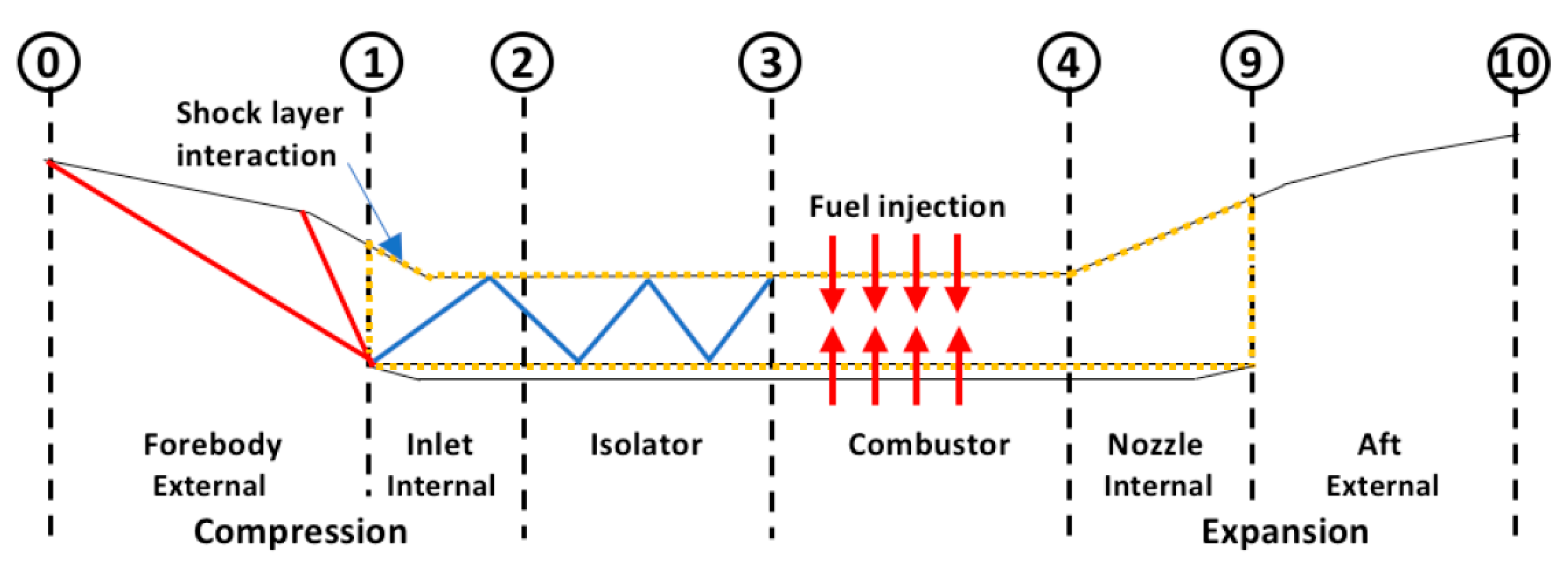
- Compression section (Station 0 to 3):
- ➢
- Station 0 refers to the freestream flow just before it passes through the first shockwave.
- ➢
- Station 1 refers to the end of the forebody of the vehicle.
- ➢
- Station 2 is the end of the inlet compression surfaces.
- ➢
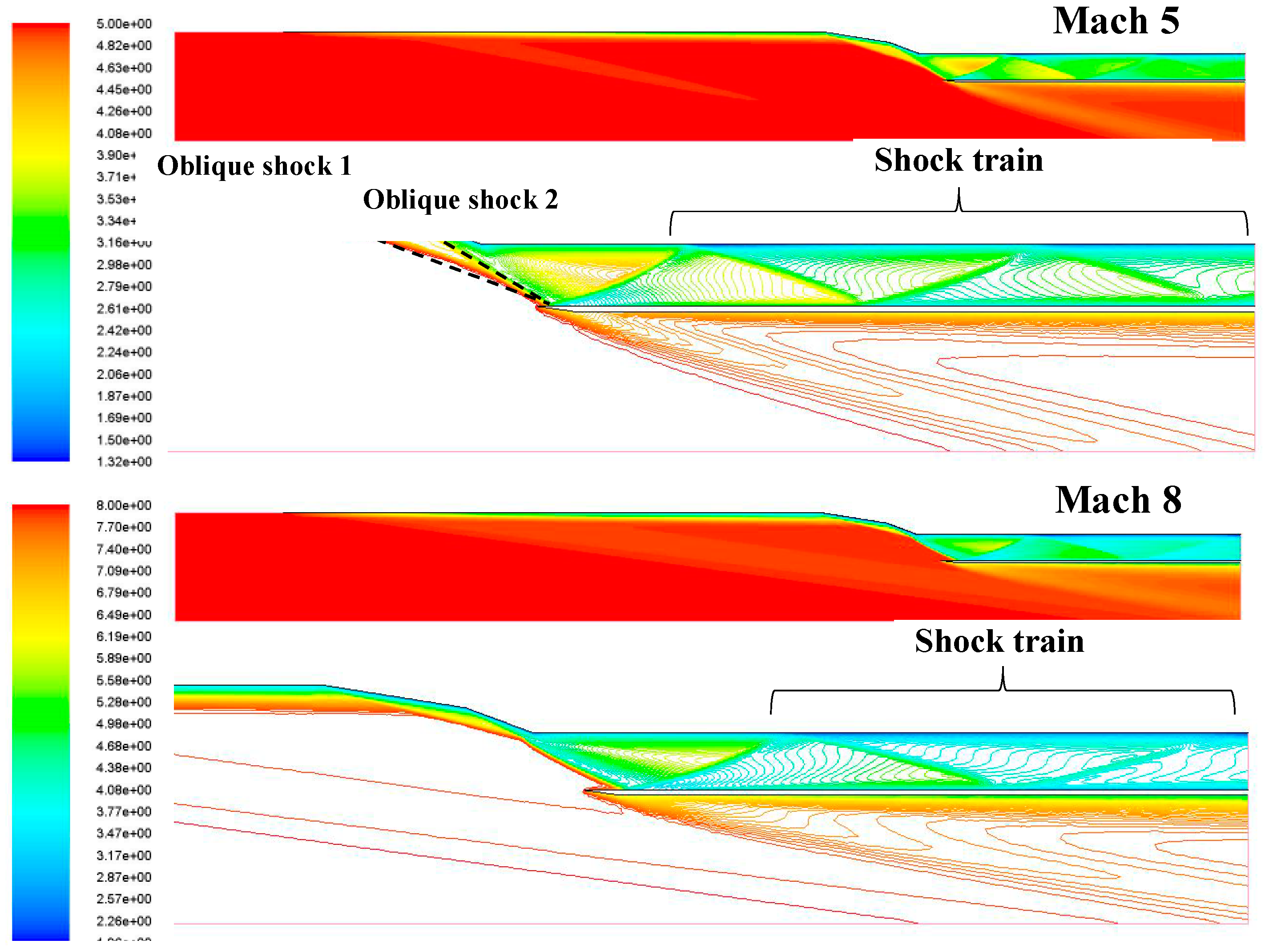
- The region between the Stations 2 and 3 is known as the isolator, which contains the shock train.
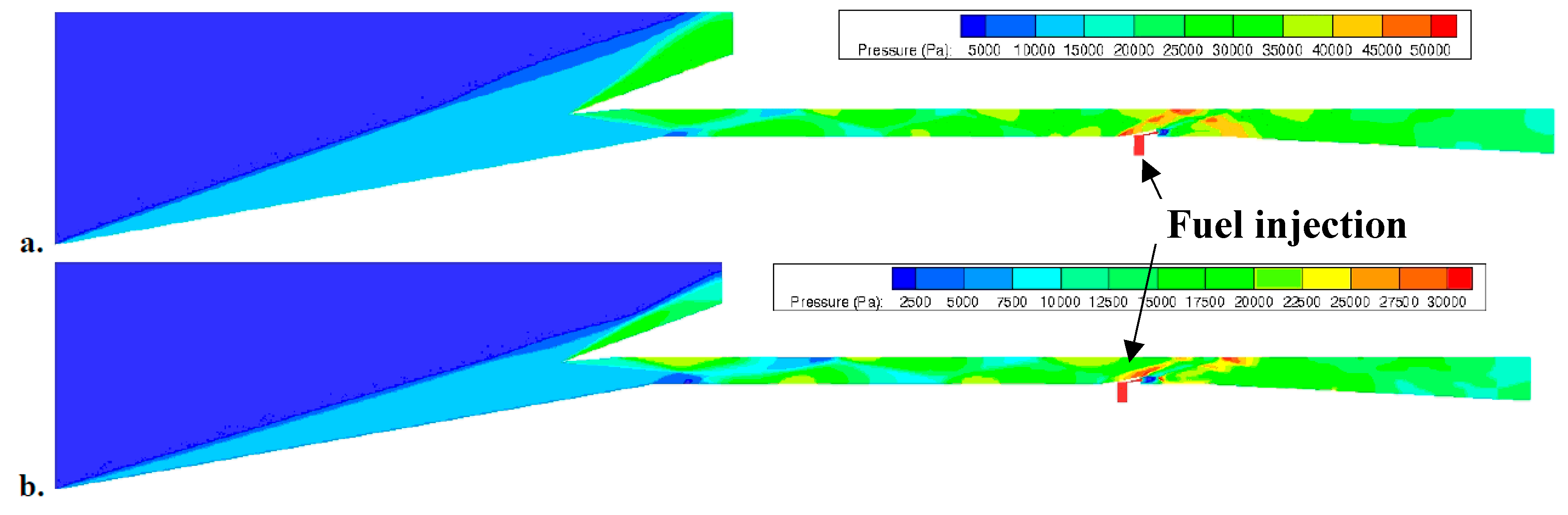
- Combustion section (Stations 3 to 4): Between station 3 and 4 is the combustion chamber where fuel is injected at supersonic velocity into the airflow, the fuel self-ignites due to the extreme pressure and temperature of the oncoming compressed flow.
- Expansion section (Stations 4 to 10): Between station 4 and 9 is the nozzle where expansion takes place internally. Station 9 and 10 is the external expansion surfaces, which makes up the vehicle’s aft.
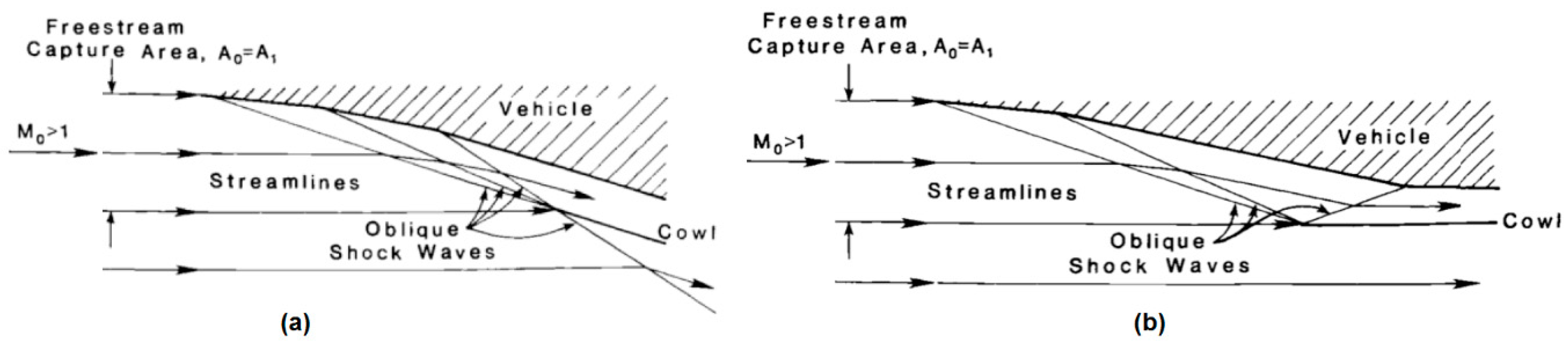
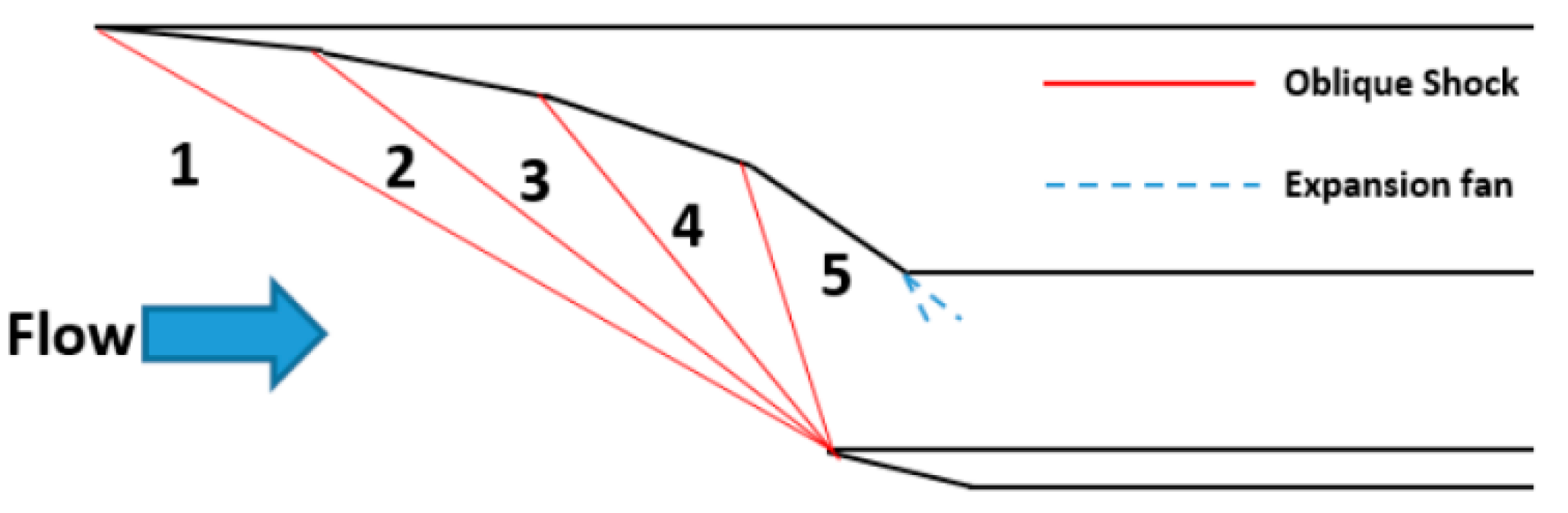
2.1. Compression Section (Station 0 to 3)
- (1)
- External compression;
- (2)
- Mixed compression;
- (3)
- Internal Compression;
2.2. Isolator
2.3. Combustion Section
2.4. Expansion Section
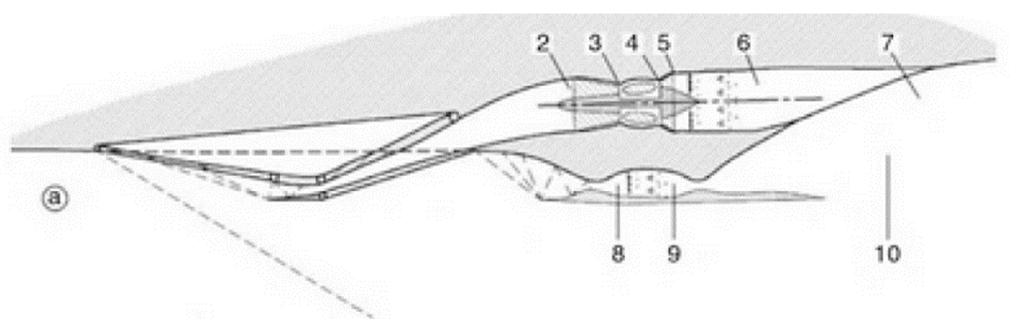
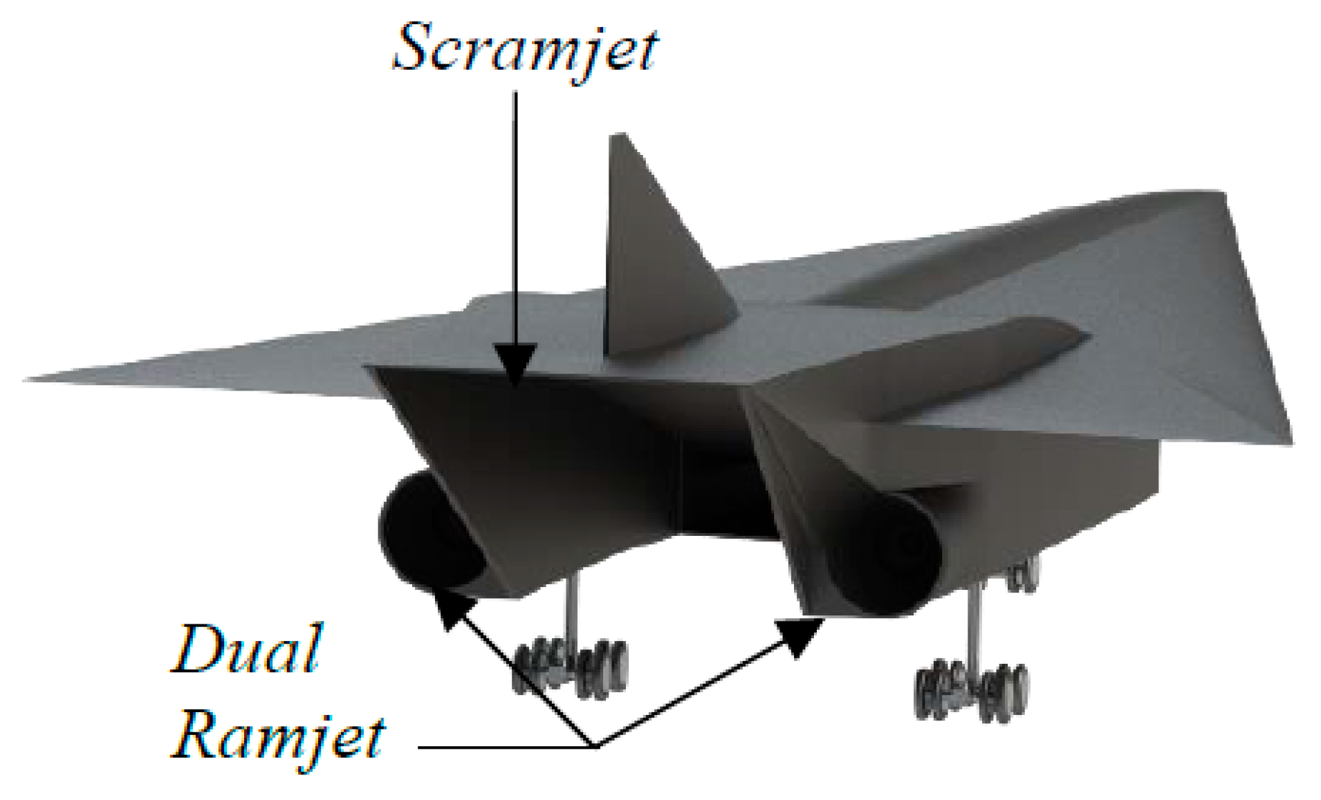
2.5. Integration of Engines into Vehicle
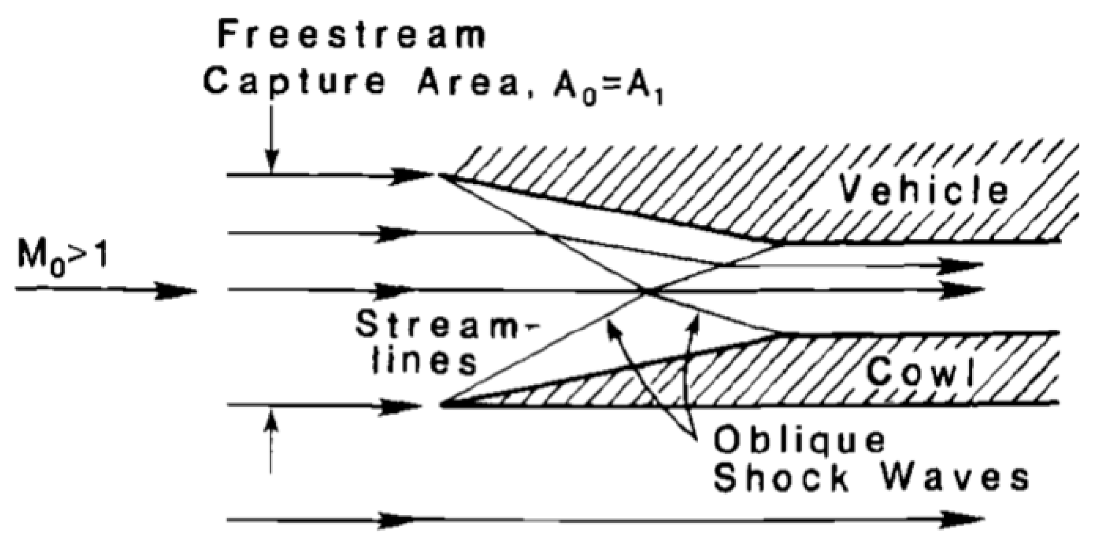
- To capture the needed air mass using the forebody under the vehicle as an external compression surface.
- The nozzle required to expand the burnt fuel-air mixture would be very large compared to the original freestream capture area in order to produce sufficient thrust, thus the aft under the vehicle is used as the external expansion surface.
- External self-contained engine would be subjected to huge amount of drag during supersonic and hypersonic speed flights.
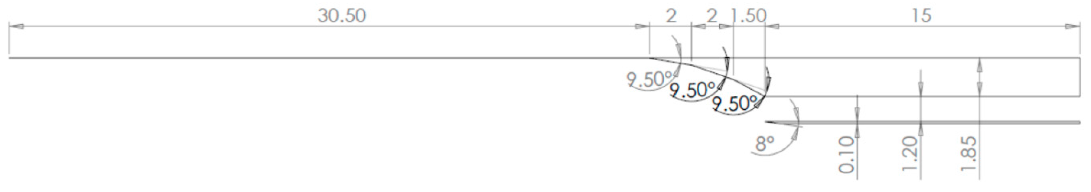
2.6. 2-D Compression System Designs
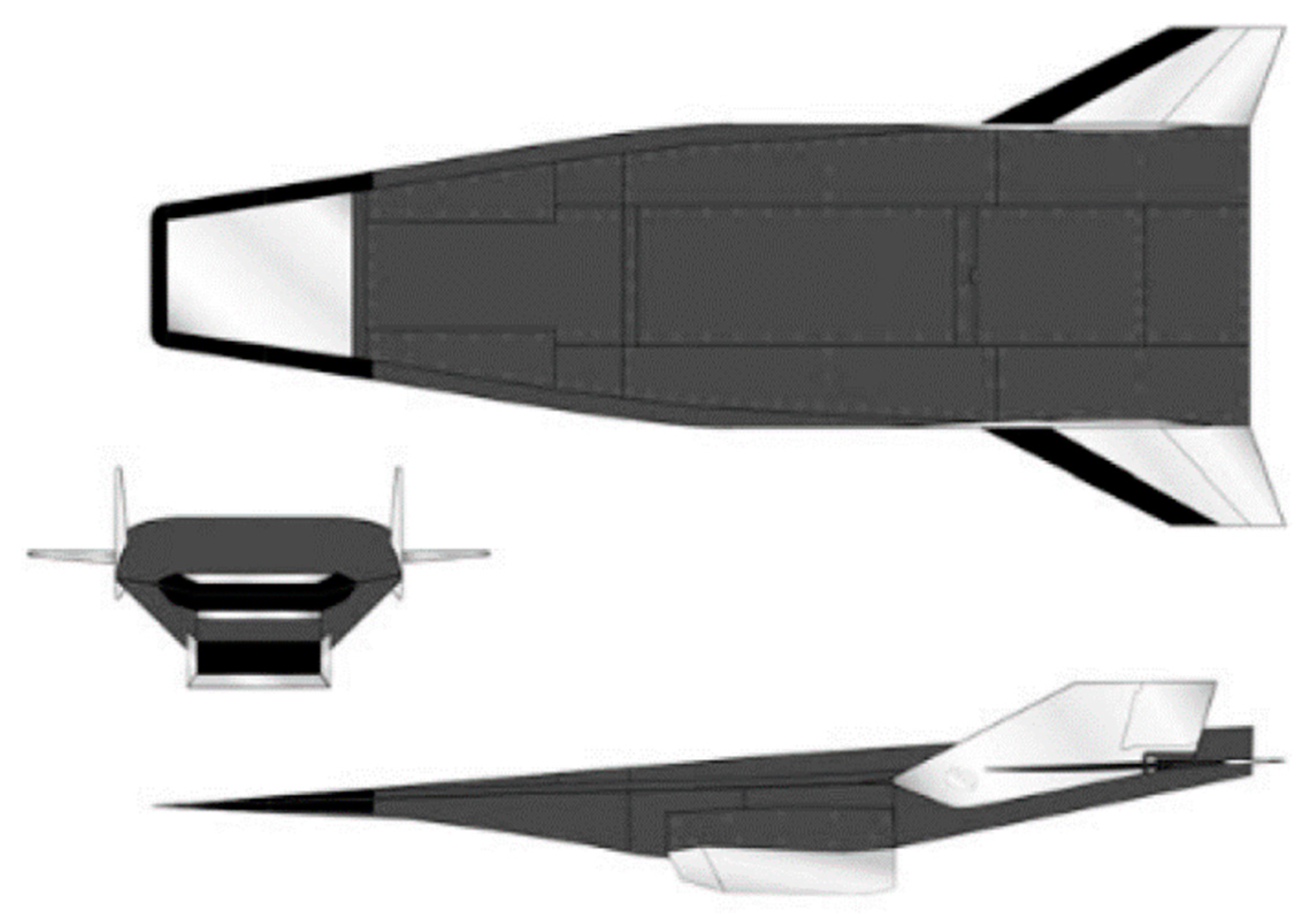
3. Concept Aircraft Specification
4. Theoretical Performance of Initial Designs
4.1. Two Ramp Inlet
4.2. Three Ramp Inlet
4.3. Four Ramp Inlet
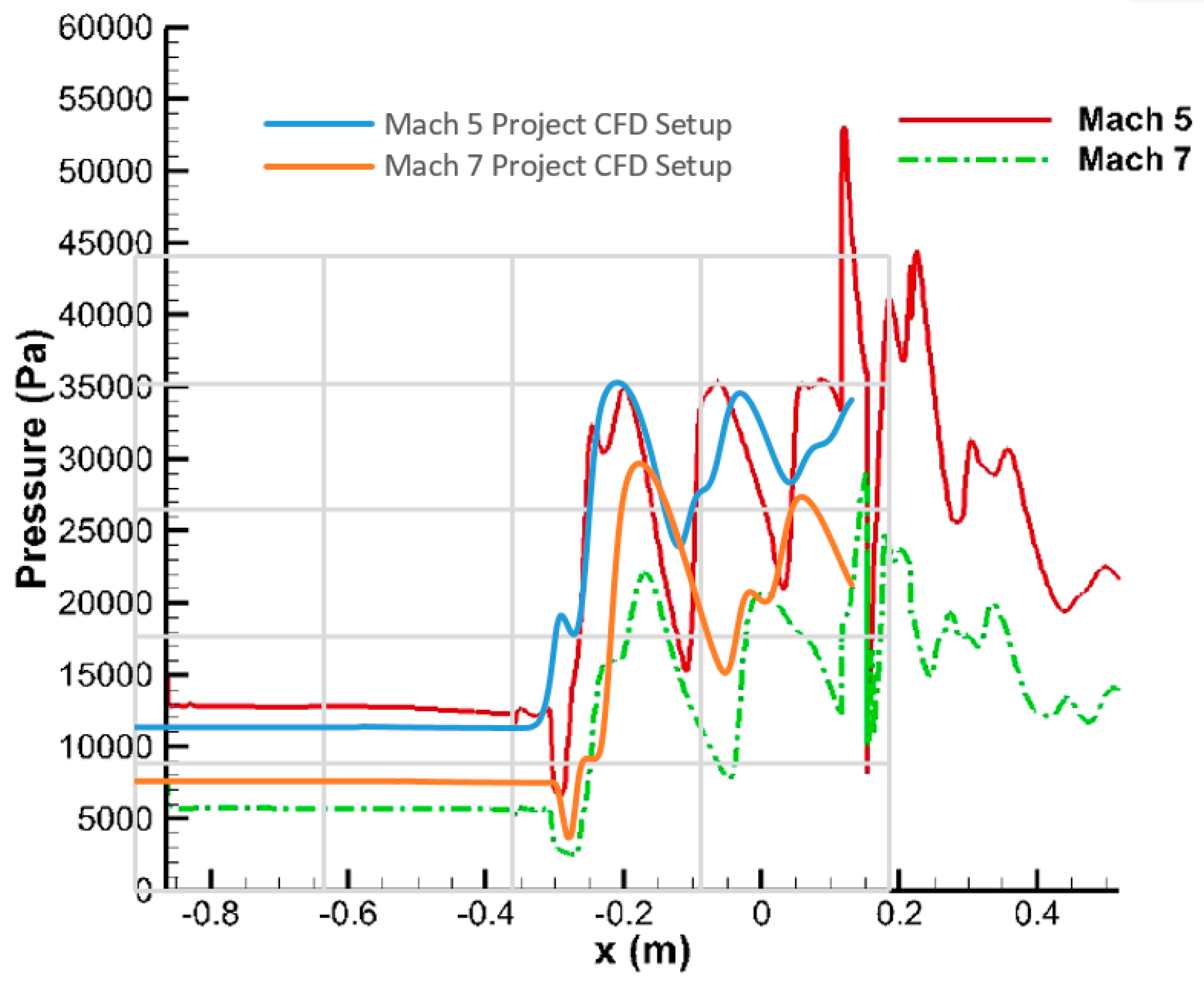
5. Computational Fluid Dynamics (CFD) Setup Validation
5.1. Two Ramp Inlet
5.2. Three Ramp Inlet
5.3. Four Ramp Inlet
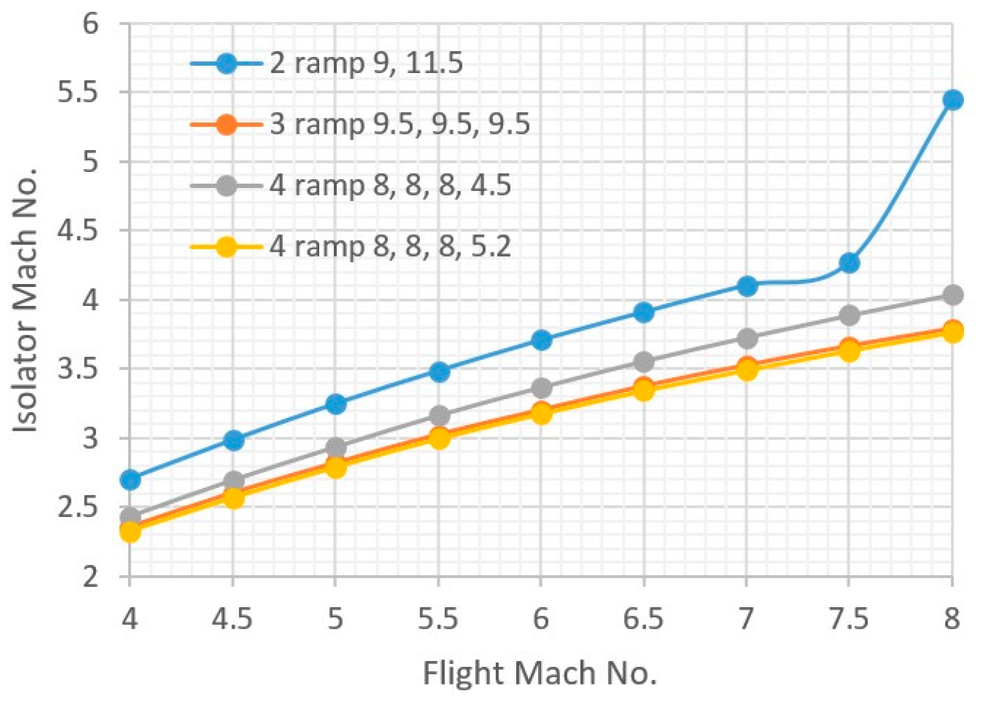
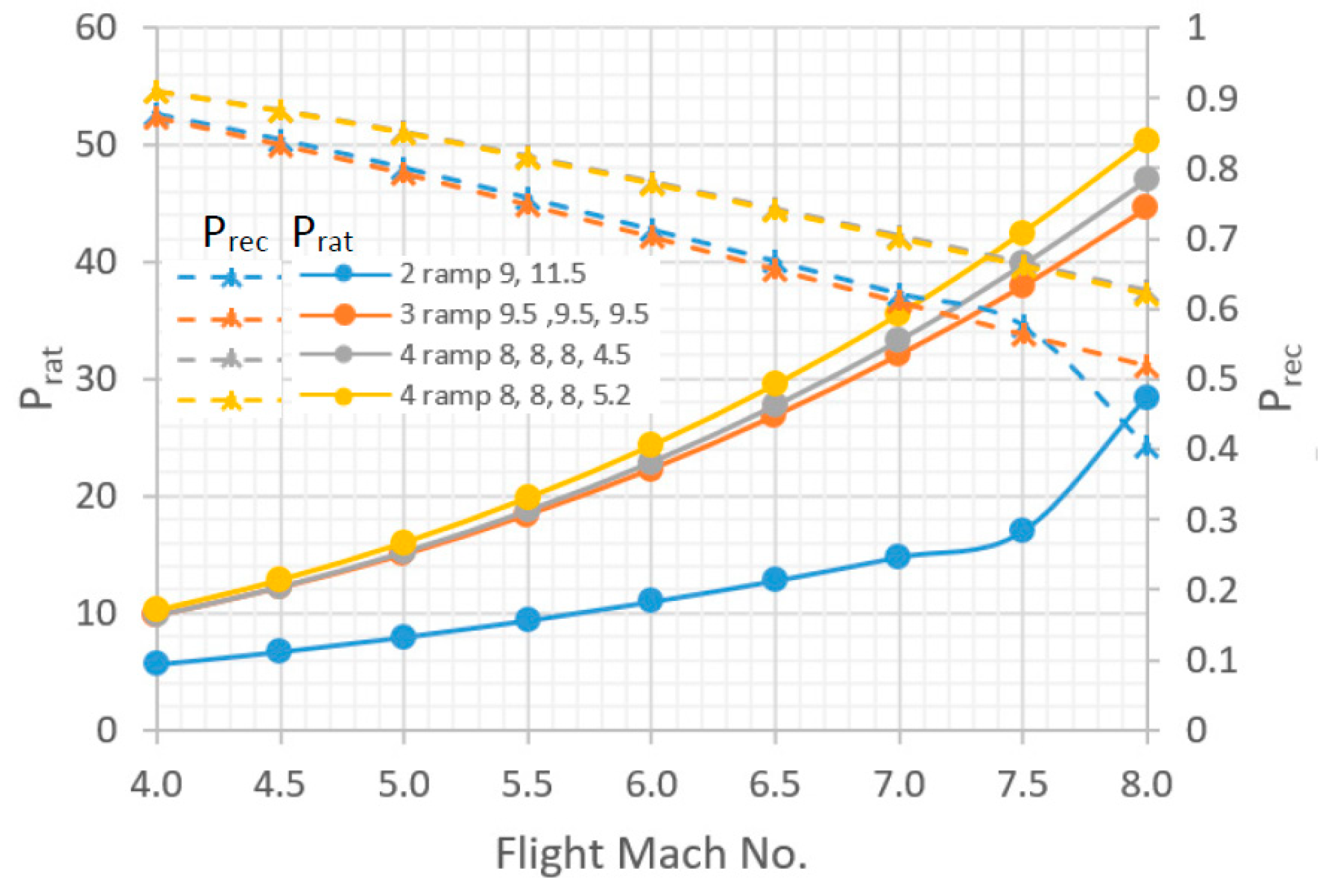
5.4. Comparison of Different Ramped Inlets
5.5. Refinement of the Four Ramp Inlet
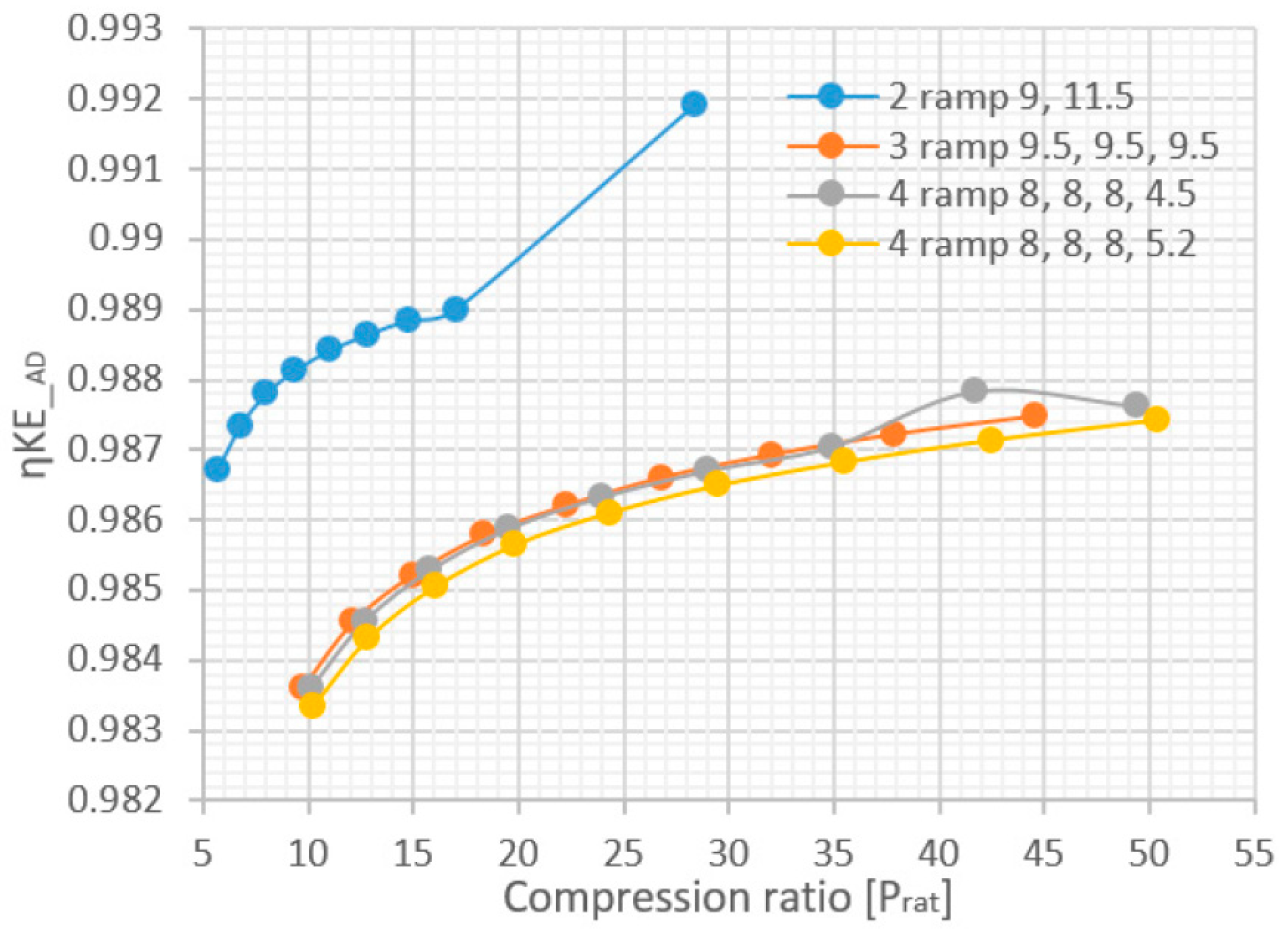
5.6. Comparison of Theoretical Performance between Inlet Designs
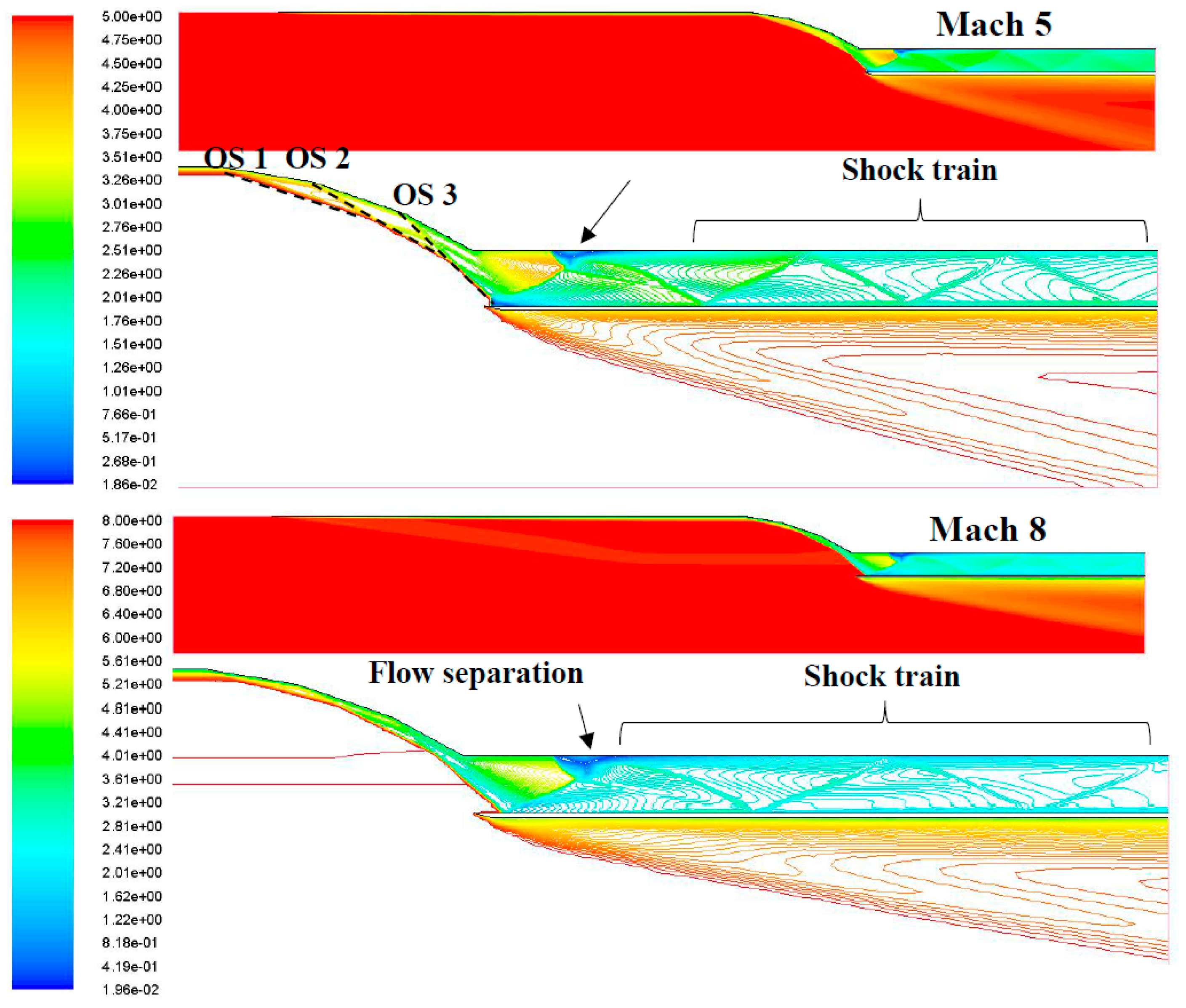
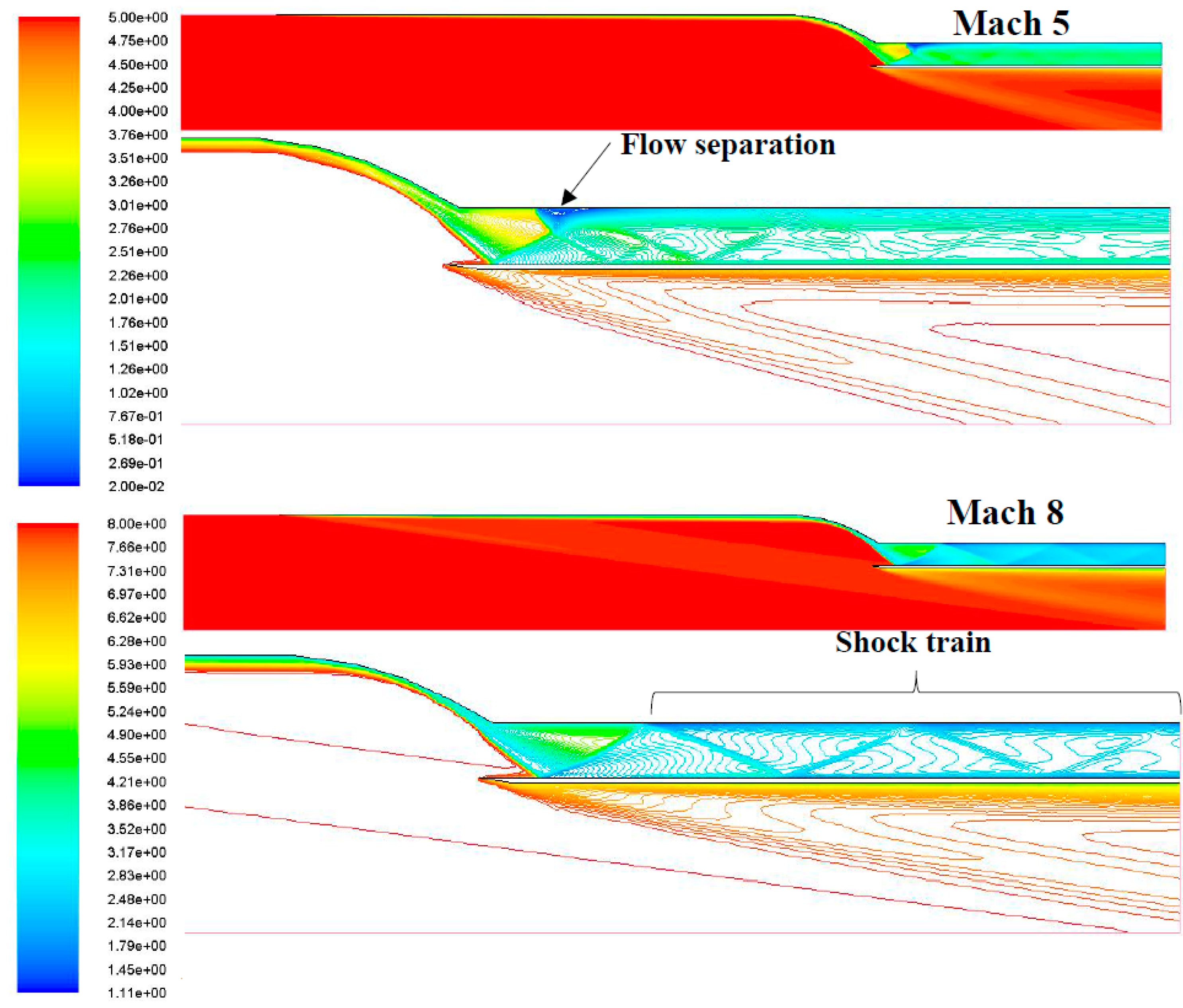
6. 2-D CFD Simulations
6.1. 2, 3 and 4-Ramp 2-D Simulation
6.2. Comparison of Finalised 2-D Compression Systems
7. 3-D CFD Simulations and Combined Cycle Engine Configuration
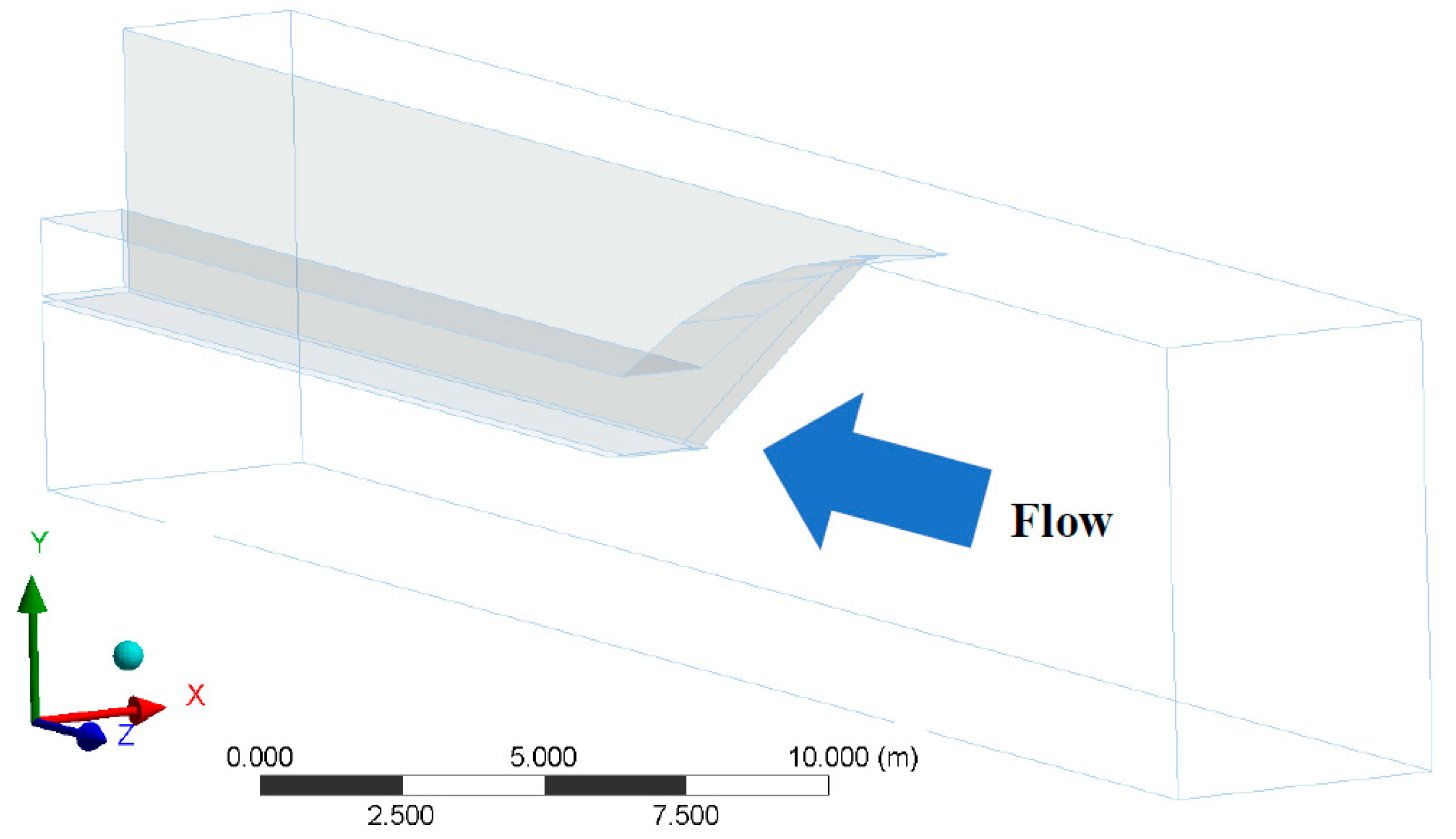
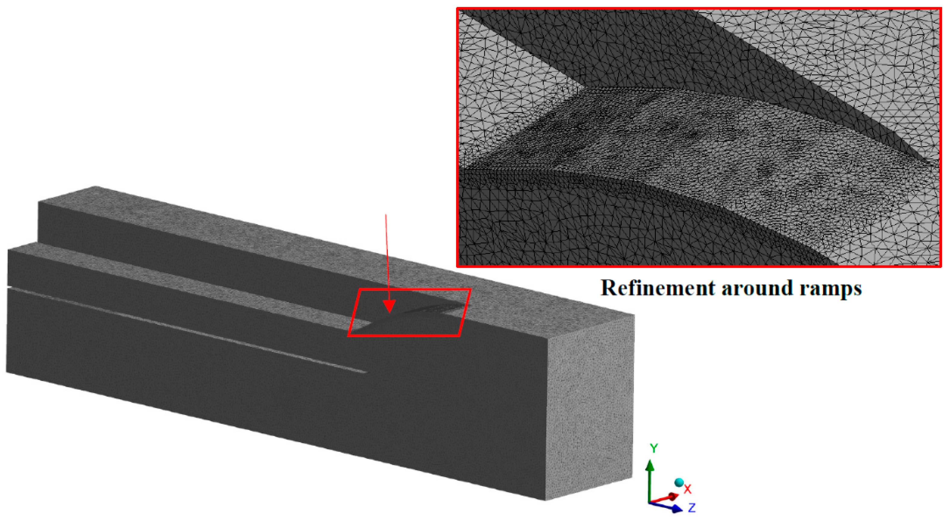
7.1. 3-D Computational Domain & Computational Fluid Dynamics (CFD) Setup
7.2. CFD Simulation Results
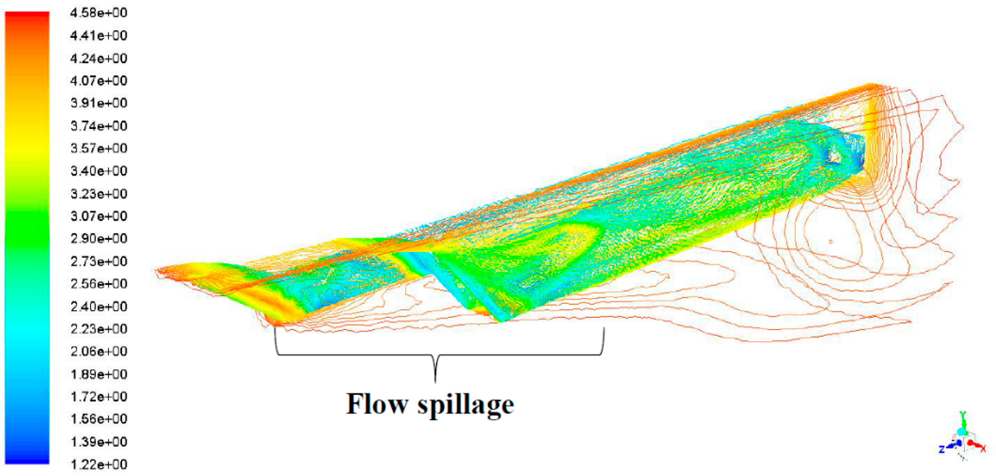
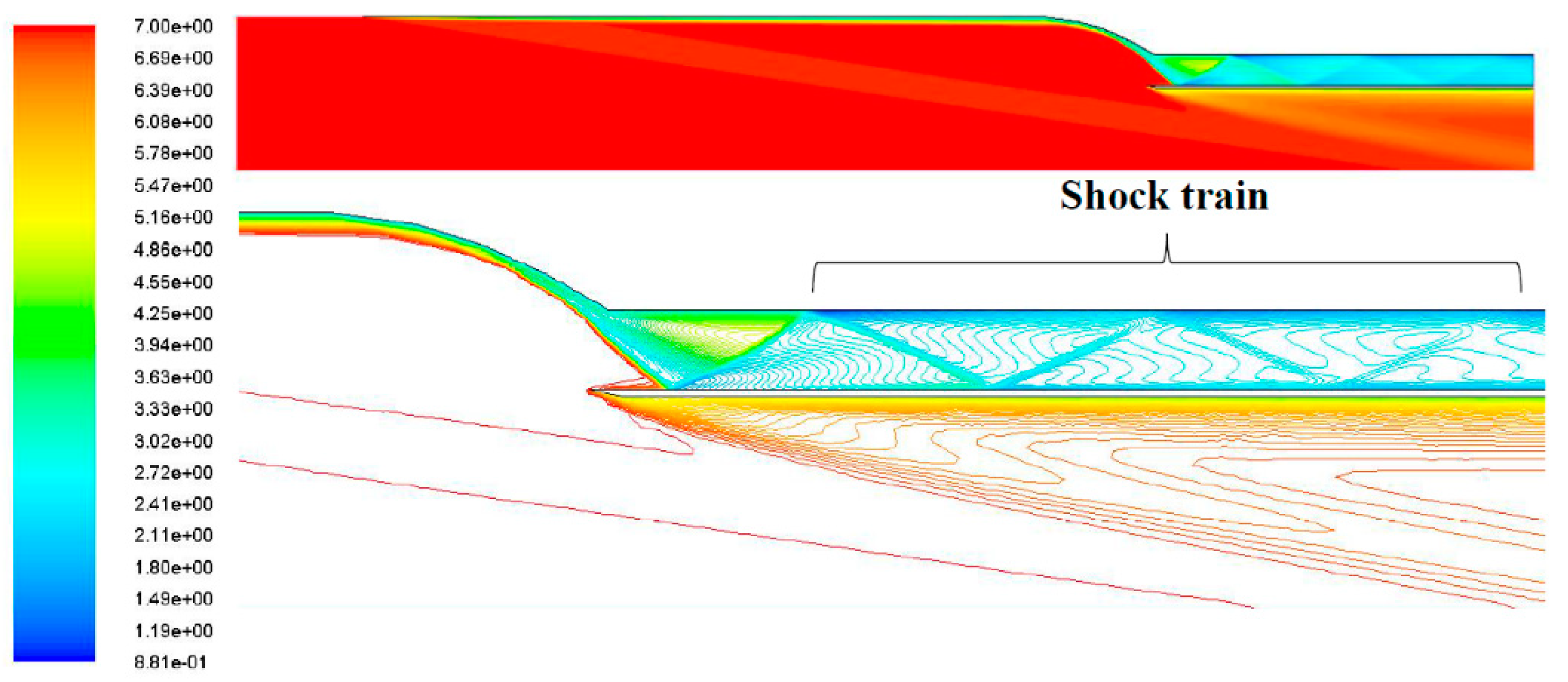
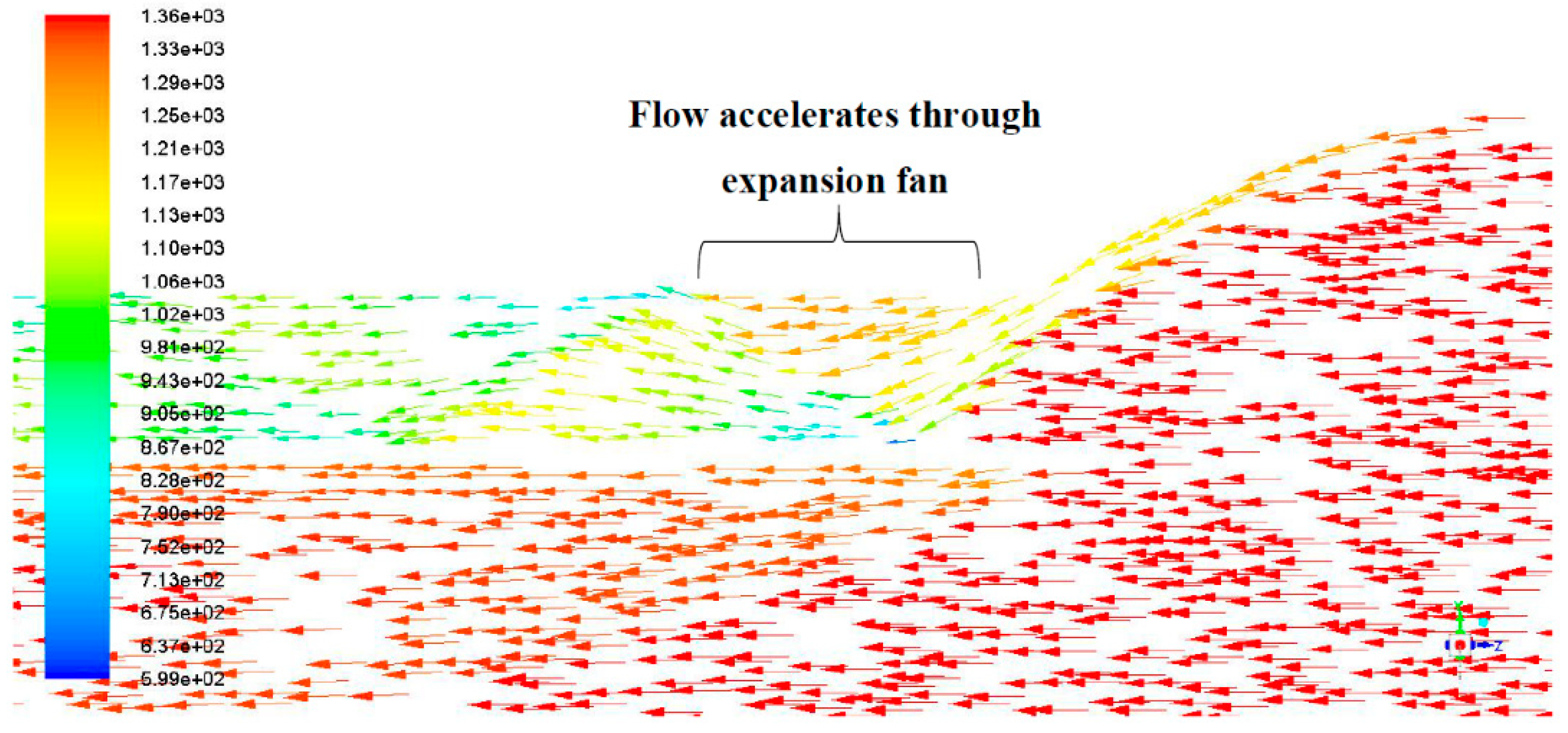
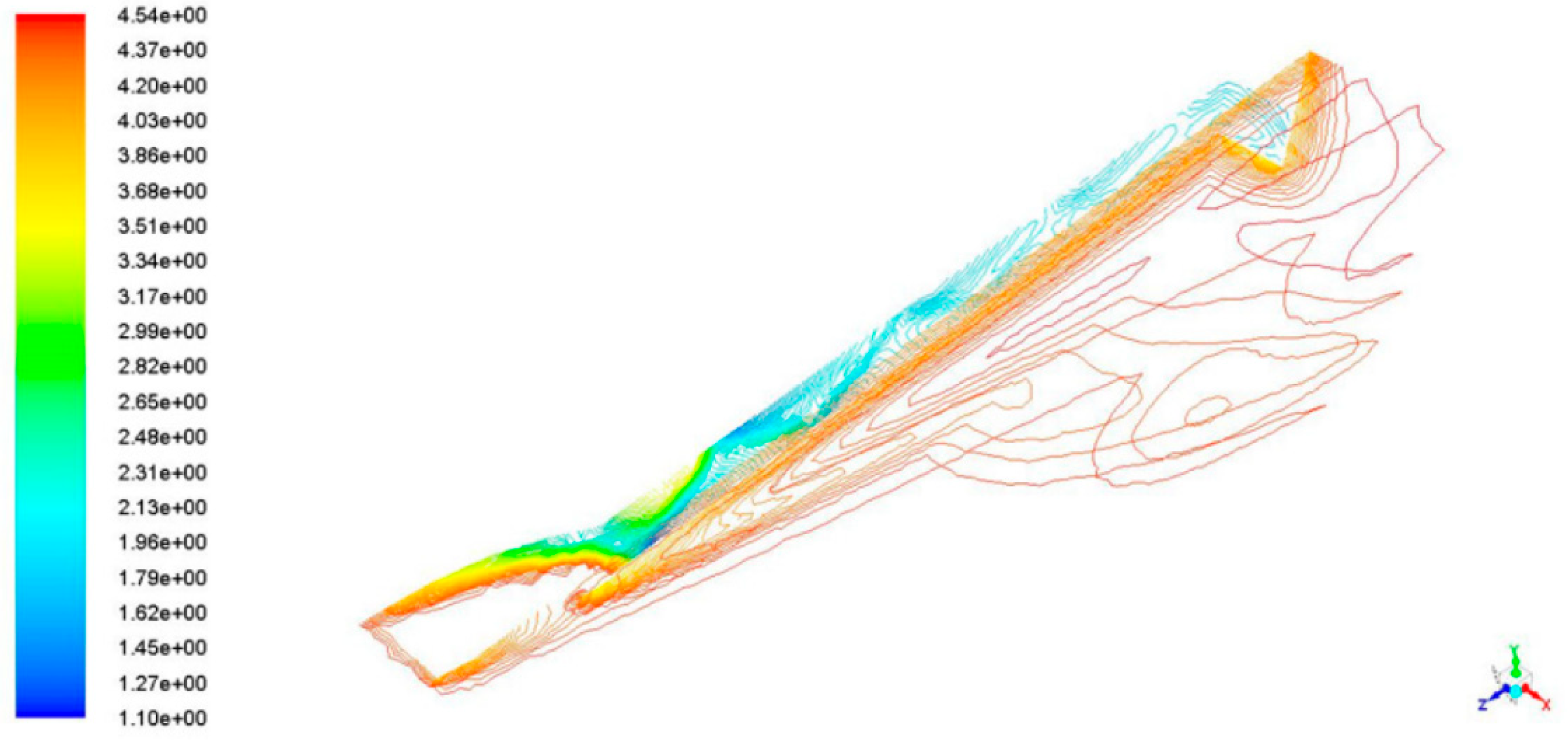
7.2.1. Mach 4.5
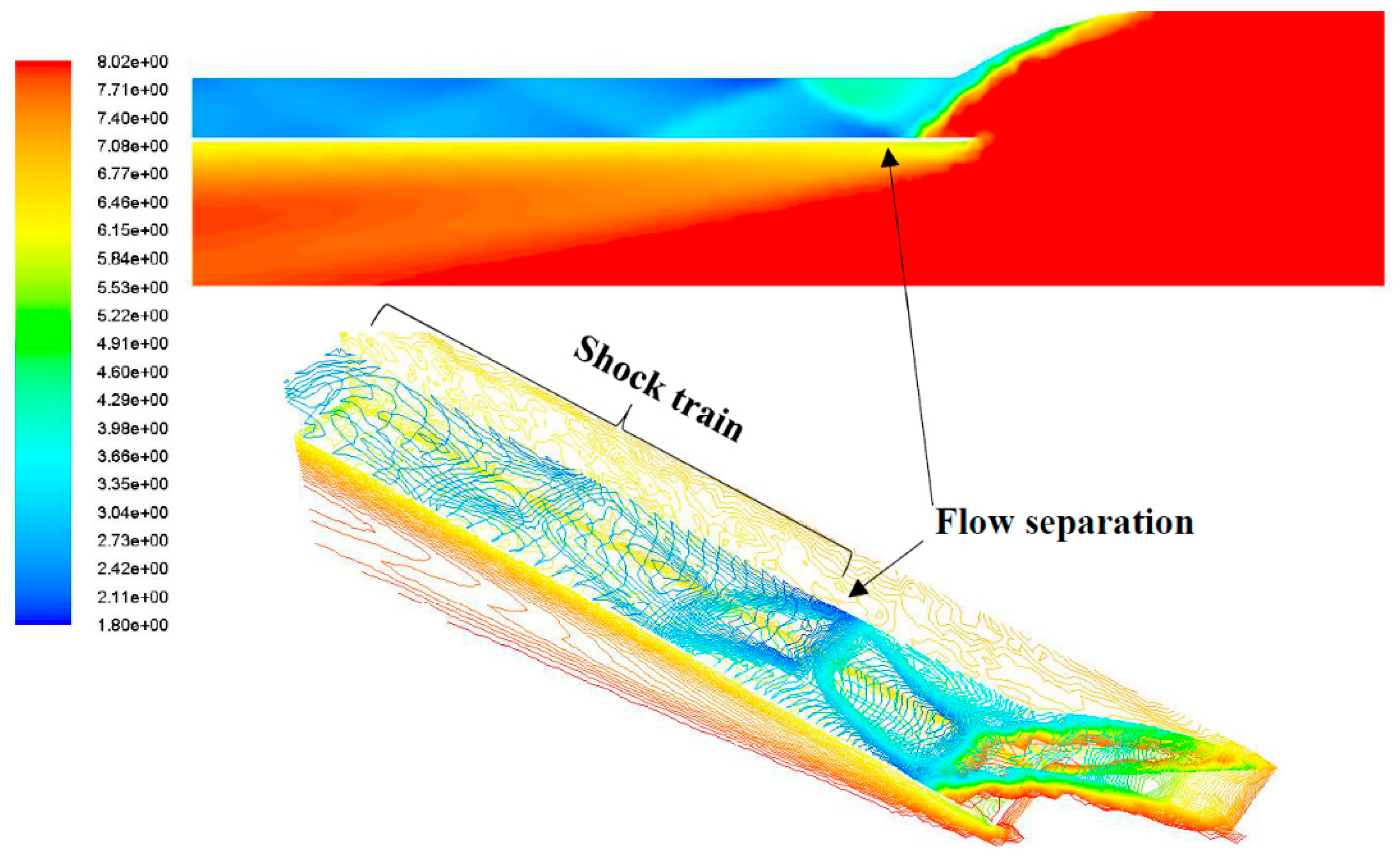
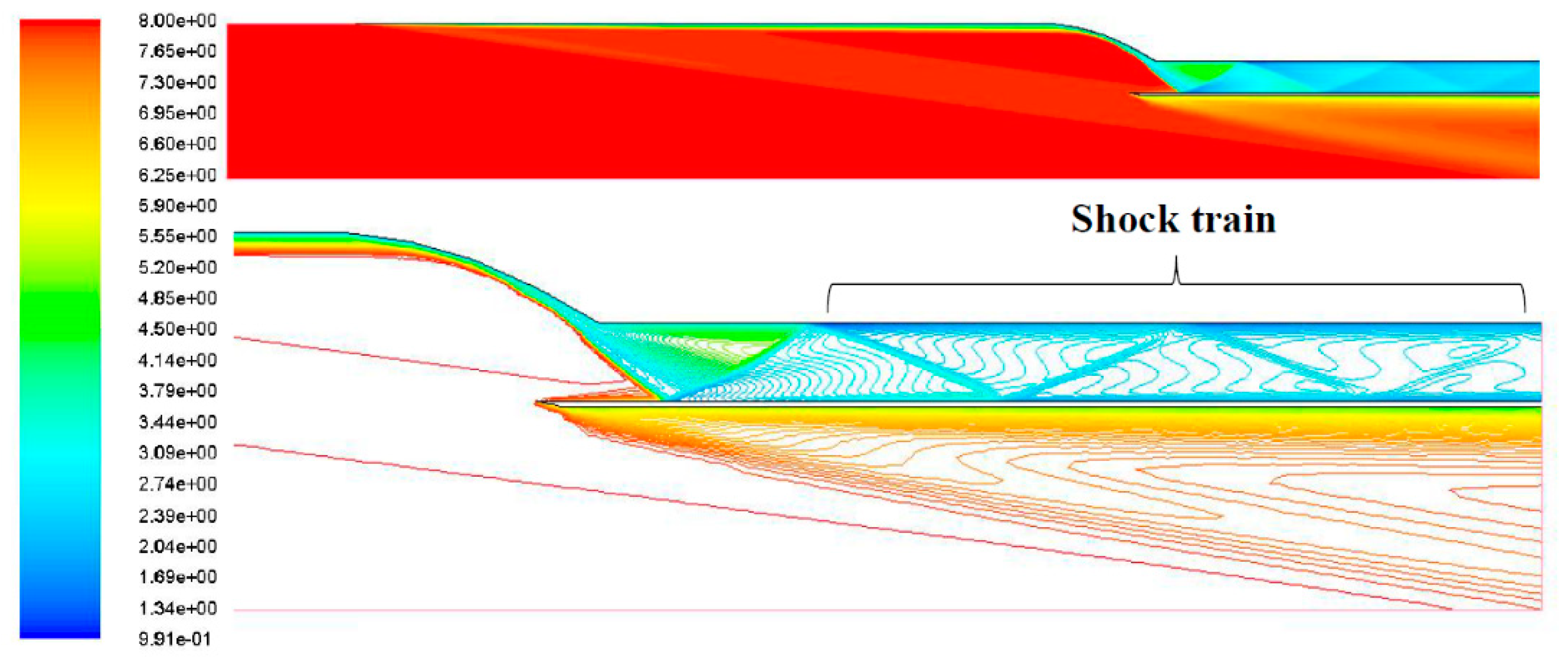
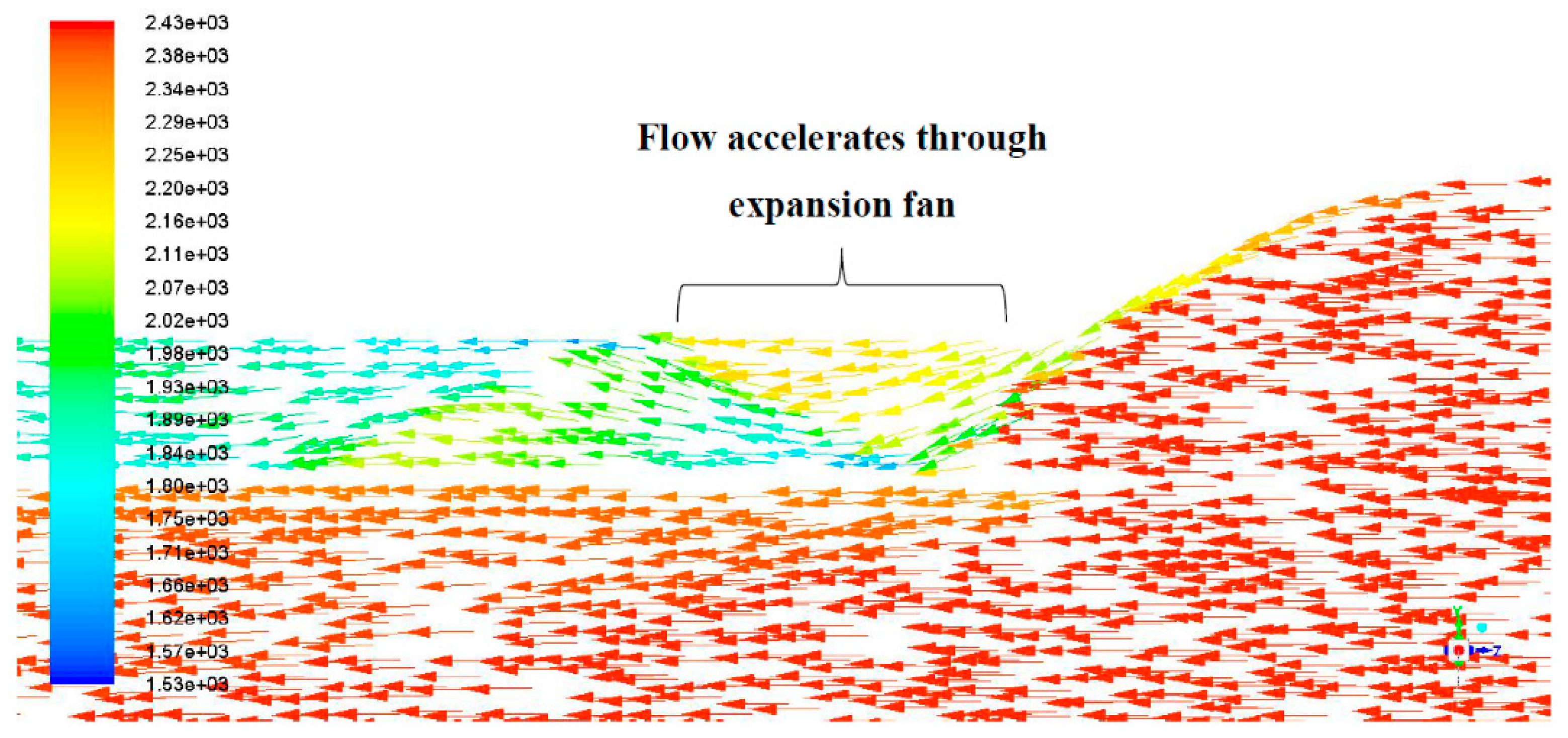
7.2.2. Mach 8
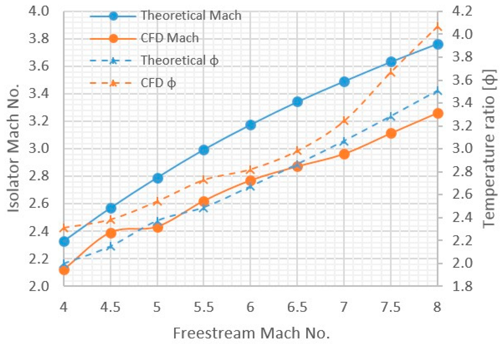
7.2.3. Comparison of Performance at Different Mach Speeds
7.2.4. Combined Cycle Engine Configuration
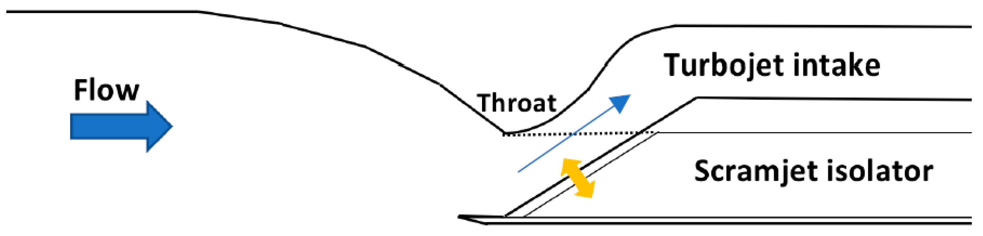
7.2.5. Integration with Turbojet Intake
7.2.6. Scramjet-Ramjet Integration
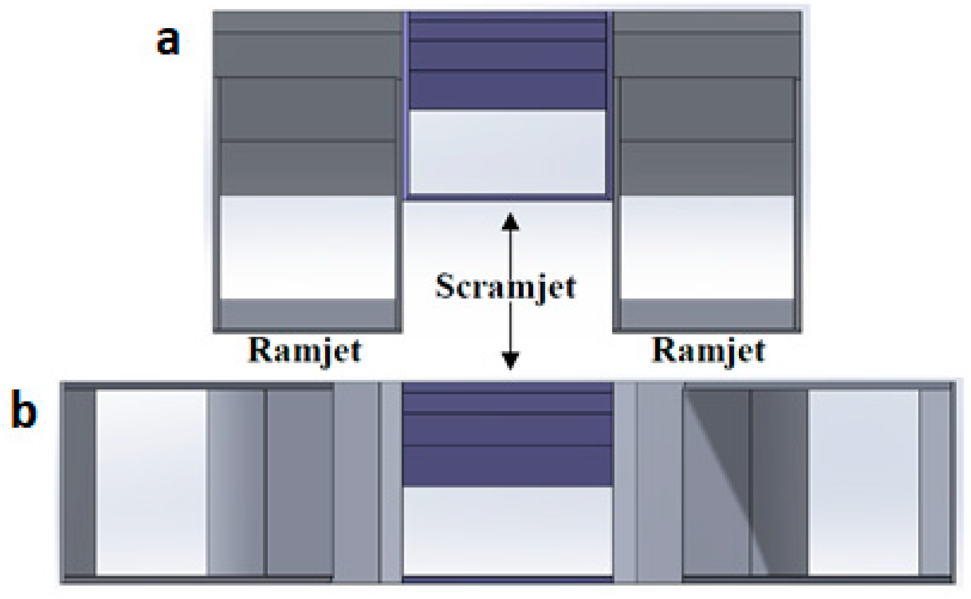
7.2.7. Same Orientation Scramjet and Ramjet Layout
7.2.8. Rotated Ramjet Layout
8. Conclusions
Author Contributions
Funding
Conflicts of Interest
References
- Siddiqui, A.M.; Ahmed, G.M.S. Design and Analysis on Scramjet Engine Inlet. Int. J. Sci. Res. Publ. 2013, 3. [Google Scholar]
- Heiser, W.; Daley, D.; Pratt, D. Hypersonic Airbreathing Propulsion; American Institute of Aeronautics and Astronautics: Washington, DC, USA, 1994; ISBN 978-1-56347-035-6. [Google Scholar]
- Goyne, C.; Cresci, D. Hy-V program overview and status. In Proceedings of the 15th AIAA International Space Planes and Hypersonic Systems and Technologies Conference, Dayton, OH, USA, 28 April–1 May 2008. [Google Scholar]
- Smayda, M.G.; Vogel, P.D.; Schultz, I.A.; Hanson, R.K.; Foelsche, R.; Tsai, C.Y.; Cresci, D.; Goyne, C.P. Hypervelocity testing of a dual-mode scramjet. In Proceedings of the 50th AIAA Aerospace Sciences Meeting Including the New Horizons Forum and Aerospace Exposition, Nashville, TN, USA, 9–12 January 2012. [Google Scholar]
- Slater, J.; Saunders, J. Increased mach number capability for the NASA Glenn 10x10 supersonic wind tunnel. In Proceedings of the 34th JANNAF Airbreathing Propulsion Conference, Albuquerque, NM, USA, 8–11 December 2014. [Google Scholar]
- Smart, M.K. How Much Compression Should a Scramjet Inlet Do? AIAA J. 2012, 50, 610–619. [Google Scholar] [CrossRef]
- Waltrup, P.J.; Billig, F.S.; Stockbridge, R.D. Engine sizing and Integration Requirements for Hypersonic Airbreathing Missile Applications. Available online: www.dtic.mil/dtic/tr/fulltext/u2/a115370.pdf (accessed on 20 February 2017).
- Smart, M.K. Scramjet Inlets; RTO-EN-AVT-185; NATO Science and Technology Organizatoin: Neuilly sur Seine, France, 2010; pp. 1–24. [Google Scholar]
- Kotteda, V.M.K.; Mittal, S. Instabilities in Air Intakes of Supersonic Air Vehicles. Directions. Available online: https://www.iitk.ac.in/aero/research-areas (accessed 22 February 2017).
- Matsuo, K.; Mochizuki, H.; Miyazato, Y.; Gohya, M. Oscillatory characteristics of a pseudo- shock wave in a rectangular straight duct. JMSE 1993, 36, 222–229. [Google Scholar] [CrossRef]
- Surzhikov, S.; Seleznev, R.; Tretjakov, P.; Zabaykin, V. Unsteady thermo-gasdynamic processes in scramjet combustion chamber with periodical input of cold air. In Proceedings of the 50th AIAA/ASME/SAE/ASEE Joint Propulsion Conference, Cleveland, OH, USA, 28–30 July 2014. [Google Scholar]
- Hall, N. Ramjet/Scramjet Thrust. NASA Glenn Research Center, 2017. Available online: https://www.grc.nasa.gov/www/k-12/airplane/ramth.html (accessed on 18 March 2017).
- Segal, C. The Scramjet Engine: Processes and Characteristics; Cambridge University Press: Cambridge, UK, 2009. [Google Scholar]
- Storm, R.; Skor, M.; Koch, L.D.; Bensor, T.; Galica, G. Pushing the Envelope: A NASA Guide to Engines; EG-2007-04-013-GRC; NASA: Washington, DC, USA, 2007.
- El-Sayed, A.F. Fundamentals of Aircraft and Rocket Propulsion; Springer: London, UK, 2016. [Google Scholar]
- Neill, S.M.; Pesyridis, A. Modeling of Supersonic Combustion Systems for Sustained Hypersonic Flight. Energies 2017, 10, 1900. [Google Scholar] [CrossRef]
- Baidya, R.; Pesyridis, A.; Cooper, M. Ramjet Nozzle Analysis for Transport Aircraft Configuration for Sustained Hypersonic Flight. Appl. Sci. 2018, 8, 574. [Google Scholar] [CrossRef]
- Roy, C.J.; Blottner, F.G. Methodology for Turbulence Model Validation: Application to Hypersonic Flows. J. Spacecr. Rockets 2003, 40, 8–11. [Google Scholar] [CrossRef]
- ANSYS. Workshop 2—Transonic Flow Over a NACA0012 Airfoil. 2010. Available online: http://imechanica.org/files/fluent_13.0_workshop02-airfoil.pdf (accessed on 19 January 2017).
- Murugesan, S.; Dilip, A.S.; Nirmalkumar, D. Computational Analysis of Scramjet Inlet. Int. J. Recent Sci. Res. 2015, 6, 3391–3403. [Google Scholar]


| Phase | Description | Altitude (ft) | Mach | Turbojet | Ramjet | Scramjet |
|---|---|---|---|---|---|---|
| 1 | Take-off and Initial Climb | 0–1500 | 0 to 1 | |||
| 2 | Climb 1 | 1500–40,000 | 1 to 2 | |||
| 3 | Climb 2 | 40,000–60,000 | 2 to 4 | |||
| 4 | Climb 3 | 60,000–100,000 | 4 to 7 | |||
| 5 | Cruise | 100,000 | 8 | |||
| Single Operation | Dual Operation | No Operation | ||||
| M1 | M2 | M3 | Compression Ratio (Prat) | Pressure Recovery (Prec) | Temperature Increase (ϕ) | Adiabatic Efficiency, ηKE,AD |
|---|---|---|---|---|---|---|
| 4.00 | 3.36 | 2.71 | 5.65 | 0.88 | 1.70 | 0.9867 |
| 4.50 | 3.74 | 2.99 | 6.73 | 0.84 | 1.81 | 0.9874 |
| 5.00 | 4.10 | 3.25 | 7.98 | 0.80 | 1.93 | 0.9878 |
| 5.50 | 4.45 | 3.49 | 9.39 | 0.76 | 2.06 | 0.9882 |
| 6.00 | 4.78 | 3.71 | 11.00 | 0.71 | 2.19 | 0.9884 |
| 6.50 | 5.10 | 3.91 | 12.78 | 0.67 | 2.33 | 0.9887 |
| 7.00 | 5.41 | 4.11 | 14.80 | 0.62 | 2.47 | 0.9889 |
| 7.50 | 5.70 | 4.27 | 17.00 | 0.58 | 2.68 | 0.9890 |
| 8.00 | 5.98 | 5.45 | 28.42 | 0.40 | 2.80 | 0.9920 |
| M1 | M2 | M3 | M4 | Compression Ratio (Prat) | Pressure Recovery (Prec) | Temperature Increase (ϕ) | Adiabatic Efficiency, ηKE,AD |
|---|---|---|---|---|---|---|---|
| 4.00 | 3.32 | 2.79 | 2.36 | 9.71 | 0.87 | 1.99 | 0.9836 |
| 4.50 | 3.70 | 3.09 | 2.60 | 12.12 | 0.83 | 2.15 | 0.9846 |
| 5.00 | 4.05 | 3.36 | 2.82 | 14.94 | 0.79 | 2.31 | 0.9852 |
| 5.50 | 4.39 | 3.61 | 3.02 | 18.35 | 0.75 | 2.50 | 0.9858 |
| 6.00 | 4.71 | 3.84 | 3.20 | 22.25 | 0.70 | 2.68 | 0.9862 |
| 6.50 | 5.03 | 4.07 | 3.37 | 26.82 | 0.66 | 2.89 | 0.9866 |
| 7.00 | 5.32 | 4.27 | 3.52 | 32.01 | 0.61 | 3.10 | 0.9869 |
| 7.50 | 5.60 | 4.46 | 3.66 | 37.88 | 0.56 | 3.33 | 0.9872 |
| 8.00 | 5.87 | 4.63 | 3.79 | 44.54 | 0.52 | 3.57 | 0.9875 |
| M1 | M2 | M3 | M4 | M5 | Compression Ratio (Prat) | Pressure Recovery (Prec) | Temperature Increase (ϕ) | Adiabatic Efficiency, ηKE,AD |
|---|---|---|---|---|---|---|---|---|
| 4.00 | 3.427 | 2.963 | 2.570 | 2.431 | 9.791 | 0.911 | 1.971 | 0.98425 |
| 4.50 | 3.817 | 3.279 | 2.839 | 2.694 | 12.243 | 0.884 | 2.120 | 0.98520 |
| 5.00 | 4.198 | 3.582 | 3.088 | 2.934 | 15.222 | 0.853 | 2.334 | 0.98590 |
| 5.50 | 4.565 | 3.871 | 3.324 | 3.163 | 18.783 | 0.818 | 2.448 | 0.98649 |
| 6.00 | 4.917 | 4.135 | 3.534 | 3.366 | 22.925 | 0.781 | 2.625 | 0.98692 |
| 6.50 | 5.254 | 4.385 | 3.729 | 3.556 | 27.778 | 0.742 | 2.813 | 0.98729 |
| 7.00 | 5.577 | 4.619 | 3.908 | 3.728 | 33.337 | 0.704 | 3.010 | 0.98760 |
| 7.50 | 5.897 | 4.841 | 4.077 | 3.889 | 39.810 | 0.665 | 3.219 | 0.98788 |
| 8.00 | 5.194 | 5.048 | 4.233 | 4.039 | 47.054 | 0.625 | 3.435 | 0.98813 |
| M1 | M2 | M3 | M4 | M5 | Compression Ratio (Prat) | Pressure Recovery (Prec) | Temperature Increase (ϕ) | Adiabatic Efficiency, ηKE,AD |
|---|---|---|---|---|---|---|---|---|
| 4.00 | 3.43 | 2.96 | 2.57 | 2.43 | 9.79 | 0.911 | 1.971 | 0.9843 |
| 4.50 | 3.82 | 3.28 | 2.84 | 2.69 | 12.24 | 0.884 | 2.120 | 0.9852 |
| 5.00 | 4.20 | 3.58 | 3.09 | 2.93 | 15.22 | 0.853 | 2.334 | 0.9859 |
| 5.50 | 4.57 | 3.87 | 3.32 | 3.16 | 18.78 | 0.818 | 2.448 | 0.9865 |
| 6.00 | 4.92 | 4.14 | 3.53 | 3.37 | 22.93 | 0.781 | 2.625 | 0.9869 |
| 6.50 | 5.25 | 4.39 | 3.73 | 3.56 | 27.78 | 0.742 | 2.813 | 0.9873 |
| 7.00 | 5.56 | 4.62 | 3.91 | 3.73 | 33.38 | 0.704 | 3.010 | 0.9876 |
| 7.50 | 5.90 | 4.84 | 4.08 | 3.89 | 39.81 | 0.665 | 3.219 | 0.9879 |
| 8.00 | 6.19 | 5.05 | 4.23 | 4.04 | 47.05 | 0.625 | 3.435 | 0.9881 |
© 2018 by the authors. Licensee MDPI, Basel, Switzerland. This article is an open access article distributed under the terms and conditions of the Creative Commons Attribution (CC BY) license (http://creativecommons.org/licenses/by/4.0/).
Share and Cite
Sen, D.; Pesyridis, A.; Lenton, A. A Scramjet Compression System for Hypersonic Air Transportation Vehicle Combined Cycle Engines. Energies 2018, 11, 1568. https://doi.org/10.3390/en11061568
Sen D, Pesyridis A, Lenton A. A Scramjet Compression System for Hypersonic Air Transportation Vehicle Combined Cycle Engines. Energies. 2018; 11(6):1568. https://doi.org/10.3390/en11061568
Chicago/Turabian StyleSen, Devendra, Apostolos Pesyridis, and Andrew Lenton. 2018. "A Scramjet Compression System for Hypersonic Air Transportation Vehicle Combined Cycle Engines" Energies 11, no. 6: 1568. https://doi.org/10.3390/en11061568
APA StyleSen, D., Pesyridis, A., & Lenton, A. (2018). A Scramjet Compression System for Hypersonic Air Transportation Vehicle Combined Cycle Engines. Energies, 11(6), 1568. https://doi.org/10.3390/en11061568