Article

Reliability and Maintenance Prioritization Analysis of Combined Cooling, Heating and Power Systems

1
Faculty of Environmental Engineering, the University of Kitakyushu, Kitakyushu 808-0135, Japan
2
School of Environmental and Municipal Engineering, Jilin Jianzhu University, Changchun 130118, China
*
Author to whom correspondence should be addressed.
Energies 2018, 11(6), 1519; https://doi.org/10.3390/en11061519
Submission received: 5 May 2018 / Revised: 6 June 2018 / Accepted: 7 June 2018 / Published: 11 June 2018
(This article belongs to the Section F: Electrical Engineering)

Abstract

:
A combined cooling, heating, and power (CCHP) system is a complex and repairable system containing a large number of components and series of subsystems. When a failure occurs in one component, it might cause a failure of a subsystem or whole system. Traditional maintenance methods might lead to the waste of maintenance resources and a high cost of maintenance. The reliability and maintenance prioritization analyses can help managers optimize maintenance strategies and reduce the total cost. A reliability importance index is one of the factors in maintenance prioritization analysis. This paper aims at selecting the component reliability importance indices to identify the priority of component maintenance of a CCHP system from the perspective of maintenance cost. Failure cost importance index (FCI) and Potential failure cost importance index (PI) are developed for the maintenance prioritization analysis of a CCHP system. A Markov model based on the state–space method (SSM) is used to analyze the reliability and availability of a CCHP system. A set of actual survey reliability data of CCHP systems is used to support the validity of the reliability importance indices. The results indicate that the FCI and PI might lead to different rankings of maintenance prioritization. The FCI and PI will help managers make a reasonable decision for maintenance on a cost basis.

1. Introduction

Combined cooling, heating, and power (CCHP) systems produce electricity and available heat from one generation site and the conversion efficiency of primary energy to useful energy is approximately 70–80% [1,2]. Due to the high conversion efficiency and greater environmental benefit, CCHP systems have attracted more attention in the past few decades [3] and are widely used in buildings or regional energy systems [4]. The CCHP system, also known as the tri-generation system, can be applied in a stand-alone microgrid (MG) or combined with the city power grid.
Recent research is focused on system management, operation, system optimization, size optimization, energy management, renewable energies, and more [5]. Some renewable energies and technologies have been applied in the CCHP system, such as fuel cells, heat pumps [6], photovoltaics (PV), wind turbines, and more [7,8]. Integrating renewable energy into the CCHP system can further improve the system’s energy efficiency and reduce carbon dioxide emissions; the renewable energies integrated into CCHP (RECCHP) systems can be used when the power grid is unavailable, for example, on islands, and in deserts [9]. Chen et al. [10] proposed a multi-objective optimization model of energy management for the integrated electrical and natural gas network with CCHP plants. Lo Basso et al. [6] analyzed the thermal management and off-design operation of coupling of combined heat and power (CHP) and heat pump for the energy retrofitting of residential buildings. Wang et al. [11] presented a comprehensive operation model to enhance the economic and environmental benefits through the improved CCHP strategy of MG. The main objective of optimization is to improve energy efficiency, maximize environmental benefits, and reduce the expense of the system. Some previous studies on system design and optimization of a CCHP system were often set to a constant, or assumed that the reliability and maintenance of the system were completely unfailing for operation [12]. The cost of operation and maintenance of a system account for more than 50% of the total cost of the whole life cycle [13] in fact. Thus, a reasonable maintenance strategy can improve the reliability of a system and reduce the maintenance cost.
Some articles on the operation, reliability, and maintenance of a CCHP system or microgrid are related to facilities’ distribution and system optimization design. Ou [14] proposed an unsymmetrical faults analysis method to deal with the unsymmetrical faults of microgrid distribution systems adopting hybrid compensation. Ting-Chia Ou et al. studied the operation and control strategies for a microgrid which used renewable energies and fuel cells as power generators [15]; a technology was developed to improve the transient stability in the hybrid power multi-system [16]. Noussan et al. [17] proposed an optimization tool to enhance the operation of a CHP system combined with a heat pump. Zamani-Gargari et al. [18] proposed a method which combined the Monte Carlo Simulation (MCS) method to assess the reliability of a wind power system with energy storage. Yang et al. [19] proposed an approach to analyzing how the wind farm electrical system influenced the system when the electrical system faulted. Wang [20] presented a reliability and availability analysis of a redundant and non-redundant BCHP (building, cooling, heating, and power) system, but did not consider the component reliability of the system. Haghifam, and Manbachi [21] proposed a reliability and availability modeling of CHP systems to analyze the impact of CHP system reliability with improved gas-delivery, water-delivery, and hot water-delivery subsystems but did not model the reliability of individual components. Frangopoulos [22] analyzed the effect of optimization on the synthesis, design, and operation of a cogeneration system based on reliability considerations, but did not consider the effect of component reliability. El-Nashar [23] presented an optimal design model of a cogeneration system using the thermoeconomic theory to carry out the design optimization.
Only a few articles to date have studied the component reliability of the power generation plant, cogeneration system, and CCHP system. Sabouhi et al. [24] mentioned a reliability model to assess the combined cycle power generation plants and applied it to a reliability analysis for gas turbine power plants and steam turbine power plants. The reliability of components was used to compute the system availability and the study compared the availability, but did not mention the importance of maintenance regarding the components in one system. Carazas et al. [25] presented an availability analysis for component maintenance policies of a gas turbine, but did not assess the reliability of the whole power generation system. A CCHP system is a complex system, however, containing a large number of components and a series of subsystems. When a failure occurs on one component, it might cause a failure of a subsystem or the whole system. The reliability of the whole system is dependent on the reliability of each component of the system.
Traditionally, the maintenance of components in a system is managed by specifying a fixed schedule. Each component of a system has its own maintenance schedule performed according to the manufacturer’s recommendations. It might lead to the waste of maintenance resources and a high cost of maintenance. To comprehensively evaluate the degree of maintenance importance regarding the components of a whole system and propose a reasonable maintenance strategy is a vital way to avoid the wastage of maintenance resources and reduce the total costs, therefore, the reliability and maintenance prioritization analysis of components of a whole system is necessary.
A reliability importance index is one of the methods to identify system weaknesses and provide a numerical value to determine which components are more important for the improvement of system reliability [26]. The reliability importance index can be used to assess which components are needing maintenance and which components are needing more attention to reduce maintenance costs [27]. It can provide a reference for system designers and managers to optimize the design plan and operation strategy for future design, redesign, and operation to reduce the total cost and improve reliability. Conventional reliability importance indices are a function of component reliability, however; they cannot be used directly to optimize maintenance costs.
Two new reliability importance indices are developed in this study based on the component failure cost for the identification of component maintenance priorities from the perspective of maintenance cost. A comparative analysis is performed between the new reliability importance indices and conventional reliability importance indices. Additionally, a Markov model based on the state–space method (SSM) is used to analyze the reliability and availability of components and subsystems of a CCHP System. This study is validated by actual survey reliability data of the CCHP system in Kitakyushu Science and Research Park (KSRP), Kitakyushu, Japan; the system has been operational since July 2001.
This paper is organized as follows: Section 2 introduces the main components of a CCHP system and the CCHP system at Kitakyushu Science and Research Park, the applied objective; Section 3 describes the methodologies of reliability analysis and reliability importance analysis; Section 4 analyzes the reliability of a CCHP system; Section 5 presents the numerical calculations and dissection of the case; Section 6 outlines the conclusions.

2. Main Components of CCHP Systems

Several technologies have been applied to CCHP systems for power generation, waste heat recovery, thermal storage, and thermal energy conversion such as an Absorption chiller. The main components of technologies are the keys to system reliability. The main components and subsystem technologies of a CCHP system are listed in Table 1 [7,28]. Some auxiliaries and components are not listed in this table, such as cooling pumps, cooling towers, control panels and so on, but these components also have an influence on the subsystem or system reliability. Hence, auxiliaries and components will be considered in the reliability analysis of the system.
The CCHP system at Kitakyushu Science and Research Park (KSRP) [29] is the analysis objective. The Kitakyushu Science and Research Park is located in Kitakyushu, Japan. The generation of electricity and thermal form of the CCHP system are used to meet the electricity load, space cooling load, space heating load, and hot water load of several buildings on the campus. The system scheme of the CCHP system at KSRP is shown in Figure 1 [30]. The fuel cells and gas engines fueled by natural gas are used to drive the power generation units to generate electricity. Every power generation unit has an independent cooling water system. The waste heat from the power generation unit is recovered by the heat recovery steam generator (HRSG), and the 50% recovered heat from the fuel cell is used to drive the absorption chiller to meet the space cooling load in summer and the space heating load in winter. The 50% recovered heat from the fuel cell and all recovered heat from the gas engine are used to drive the heat exchanger to meet the hot water load. Since the electricity generation of the system cannot meet the electricity load of the campus, it is necessary to purchase electricity from the electricity grid. The available gas-fired absorption chiller fueled by natural gas meets the shortage of space cooling and space heating. An auxiliary boiler fueled by natural gas is used to complement the shortage of hot water. Details of the power generation units of the CCHP system in KSRP is shown in Table 2 [30].
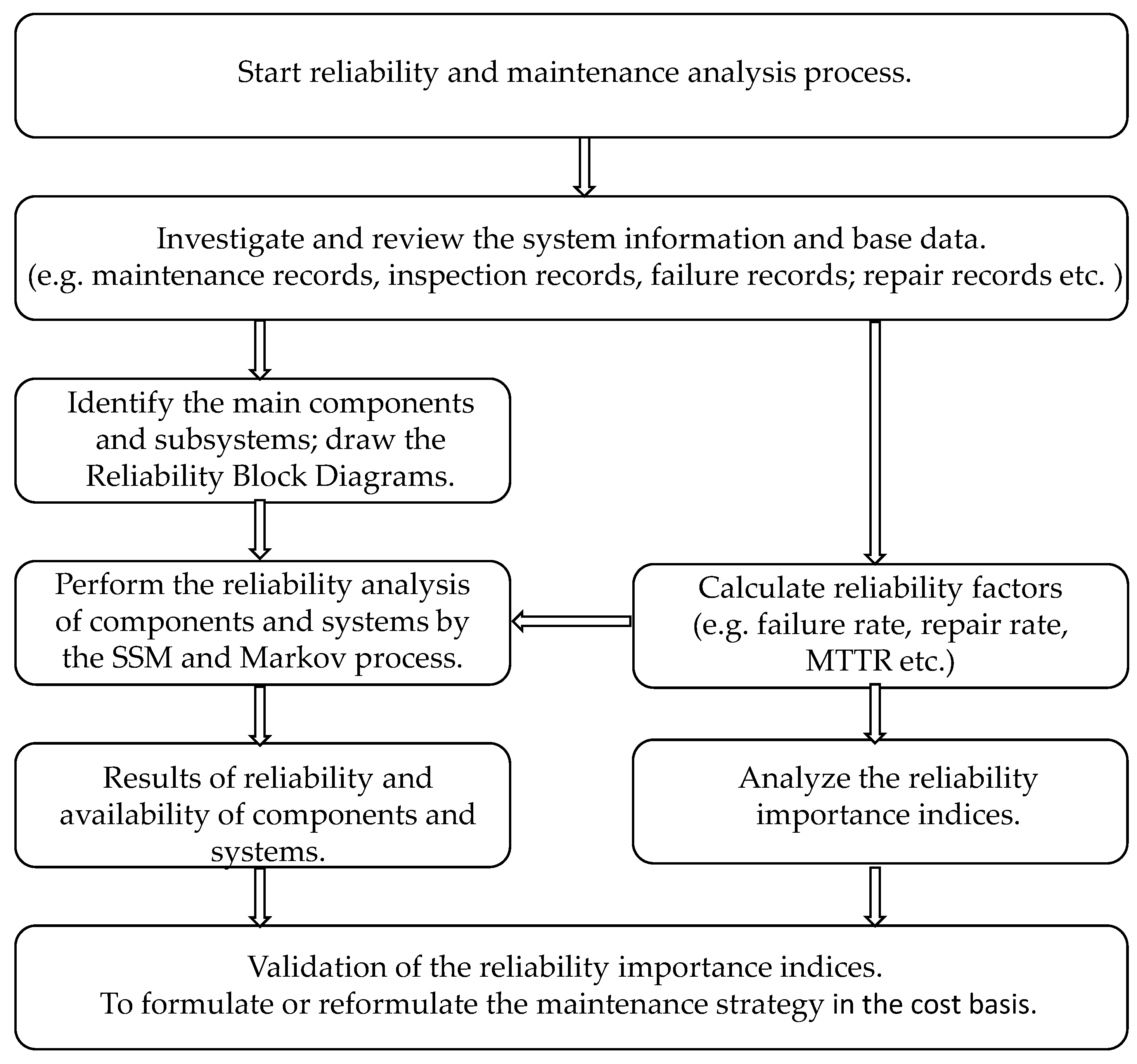
The research flow of reliability and maintenance prioritization analysis is shown in Figure 2. Reliability and maintenance prioritization analyses will be applied to the components and subsystems of the CCHP system at KSRP. The following points of system reliability are assumed for the CCHP system at KSRP:
(1)
The failure of a component or a subsystem is independent of each other. This analysis only considers one component failure and how it affects the system status and operation; multiple failures of components in the system will not be considered at this time.
(2)
When a failure occurs in a power generation unit, the outage of electricity will be satisfied by the electricity grid and the failure of the electricity grid is not considered. Similarly, the outage of space cooling/heating, and hot water is considered satisfied when the corresponding system has failed.

3. Methodology

3.1. Reliability Analysis Methods

Reliability is defined as the ability of an item to perform a required function under given conditions for a stated period. Reliability analysis methods are applied during any phase of a system’s lifetime to enhance the system’s safety, quality, and operational availability [31]. Reliability and availability analyses are widely performed in various fields, for instance, engineering and medical science, since it was proposed in the 1960s, and the most reliability analysis models and methods are proposed and applied [32]. Some widely used system reliability analysis methods, for instance, failure tree analysis, FMEA (failure modes, effects, and criticality analysis) and event tree analysis, are used to analyze the failures, failure modes, and failure effects [33]. Those analysis methods are all based on the assumption that the components or the system are only in either a functioning state or failed state. Therefore, the analysis models are rather static and not well suited for analysis of repairable systems. The reliability problems of a complex system can be described by the state of the system, and a complex system can exist in one of the multiple states. The states of a system are discrete, identifiable, and continuous in time. Some reliability analysis methods with stochastic processes are used to analyze the reliability of a repairable system, such as the Homogeneous Poisson Processes, Renewal Processes, and the Markov Processes which is the most widely used analysis method since it can be used to model systems with several states and transitions between the states [20].
Reliability assessment methods of multistate systems are based on two different approaches: analytical stochastic process and the Monte Carlo simulation method [21]. The Markov process is the main analytical stochastic process [31] since it can be used to perform the reliability analysis of a system that has changed continuously or discretely with the passage of time and space. The SSM is applicable for the assessment of reliability, availability, and maintainability of large and complex systems, and it is considered an irreplaceable method for evaluating repairable and complex systems [20,22]. The frequency-balance method is one of the analytical stochastic continuous Markov solutions used to evaluate the state probability [21]. A CCHP system is a complex and repairable system, where the function of components or systems can be restored to a certain state through repair, maintenance or replacement activities. Therefore, the Markov process, based on the state–space method (SSM), is suitable to analyze the reliability of a CCHP system.
The state of a system depends on the state of its individual components; each component has two states: functioning (1) and failed (0). Since each component has two states (functioning or failed), when a system has n quantity of components, the system will still have, at most, 2 n possible states. The state of a system is transferred randomly with time in those states. A Markov model based on a state–space method (SSM) is performed for the reliability analysis of a system with two components. The Markov model and possible states of the system are shown in Figure 3 and Table 3, respectively. The failure rate ( λ ) is represented by the transition rate of one component from a functioning state to failed state. Similarly, the repair rate ( μ )   is represented by the transition rate of one component from a failed state to a functioning state. Thus, the failure rate and repair rate of a component are used to describe the transition rate between two states of the system. The reliability and availability analysis model using the Markov process and SSM can be decomposed into the following steps:
(1)
List and classify all system states; the same state should be merged, and the non-related state should be removed.
(2)
Construct the state space diagram of the system; confirm the transition rate between states.
(3)
Calculate the probabilities of the states during a lifetime.
(4)
Calculate the reliability and availability indices, such as the failure rate (generally represented by the mean time to failure), repair rate (generally represented by the mean time to repair) and the availabilities of the components.
A steady-state distribution system is used to limit the Markov processes. Generally, a set of linear, order differential equations is established to determine the probability distribution of the system. The probability distribution equation is shown below:
P ( t ) = [ P 1 ( t ) , P 2 ( t ) , , P n ( t ) ]
where the P i ( t ) is the probability of the system in state i at time t and P ( t )   is the state probability matrix at time t.
A density matrix, Q, is defined as the following:
Q = [ q 11 q 12 q 21 q n 1 q 22 q n 2   q 1 n n q n n ]
where q i j = λ i j ( i j ) and q i i = i j λ i j .
The following state equations are presented for the steady-state probability of the system:
{ P · Q = 0 P i = 1
Thus, for a system with two components, as shown in Figure 2 and Table 3, the state transition density matrix is presented as follows:
Q = [ ( λ 1 + λ 2 ) λ 1 μ 1 μ 2 0 ( μ 1 + λ 2 ) 0 μ 2   λ 2 0 0 ( μ 2 + λ 1 ) μ 1 λ 2 λ 1 ( μ 1 + μ 2 ) ]
Based on Equation (3), the following equations can be acquired:
{ ( λ 1 + λ 2 ) P 1 + μ 1 P 2 + μ 2 P 3 = 0 λ 1 P 1 ( μ 1 + λ 2 ) P 2 + μ 2 P 4 = 0 λ 1 P 1 ( μ 1 + λ 2 ) P 2 + μ 1 P 4 = 0 μ 2 P 2 + μ 1 P 3 ( μ 2 + μ 1 ) P 4 = 0   P 1 + P 2 + P 3 + P 4 = 1
The state probabilities of the system are obtained through solving the Equations in (5), with the following results:
P 1 = μ 1 μ 2 ( λ 1 + μ 1 ) ( λ 2 + μ 2 )
P 2 = λ 1 μ 2 ( λ 1 + μ 1 ) ( λ 2 + μ 2 )
P 3 = λ 2 μ 1 ( λ 1 + μ 1 ) ( λ 2 + μ 2 )
P 4 = λ 1 λ 2 ( λ 1 + μ 1 ) ( λ 2 + μ 2 )
where the availability of component 1 is written as follows:
A c o m p o n e n t   1 = P 1 + P 3
where the availability of component 2 is written as follows:
A c o m p o n e n t   2 = P 1 + P 2
where the availability of the whole system (both component 1 and component 2 are functioning) is written as follows:
A w h o l e   s y s t e m = P 1
where the availability of the system (whole system or part of the system are functioning) is written as follows:
A s y s t e m = P 1 + P 2 + P 3
Generally, a complex system consists of multiple series and parallel subsystems, thus, the reliability calculation methods for a series subsystem and parallel subsystem are different [34]. The reliability of a series system with n components is presented as follows:
R s e r i e s = R 1 R 2 R 3 R n
The reliability of a parallel system with n components is presented as follows:
R p a r a l l e l = 1 [ ( 1 R 1 ) ( 1 R 2 ) ( 1 R n ) ]

3.2. Component Importance Indices

Reliability importance indices can be used to determine project prioritization of components in a system. Several reliability importance measures (RIM)—Birnbaum’s measure [35], Fussell–Vesely’s measure [36], Criticality importance measure [37] for instance—have been proposed in previous studies. Based on those reliability importance measures, several importance indices were developed. Reliability importance is a function of maintenance results like operation time, failure, and repair characteristics of components in a system [38]. There are many techniques to evaluate reliability importance measures (RIM), an example of which are the Monte Carlo Simulation, Markov Methods, Petri Nets, Fault Tree Analysis (FTA), and Reliability Block Diagrams (RBD) [39]. Marcantonio Catelani et al. described two metrics for the component reliability importance assessment on complex systems—credible importance potential (CIP) and improvement potential (IP) [26]. Rong Gao and Kai Yao presented some formulas for the calculation of the importance index of components of uncertain reliability systems [40]. Patrik Hilber and Lina Bertling presented two indices which evaluated the total interruption cost and those indices were applied and simulated on an electricity distribution network [41].
The Birnbaum’s measure was developed in 1969, and it is defined as follows:
I k B ( t ) = R s y s ( t ) R k ( t ) = U s y s ( t ) U k ( t )
where I k B is the Birnbaum importance (BI) of the kth component, R s y s ( t ) is the reliability of system at time t, R k ( t ) is the reliability of kth component at time t, U s y s ( t ) is the unreliability of the system, U k ( t ) is the unreliability of the kth component at time t.
Birnbaum’s reliability importance measure presented that a component would be failed at time t. Component criticality importance (CI) [37] can be used to determine the probability that the component would be failed before time t:
I k C ( t ) = R s y s ( t ) R k ( t ) · U k ( t ) U s y s ( t ) = I k B ( t ) · U k ( t ) U s y s ( t )
This paper presents new reliability importance indices based on Birnbaum’s measure and Patrik Hilber’s research. The failure cost of components has been used as an assessment factor for a reliability importance measure of a CCHP system. The component reliability importance index based on failure cost is defined as follows:
I k F = C T F λ k
where I k F   is the reliability importance index that is considered the failure cost. The unit I k F   is failure cost per failure (failure cost/f).
Reliability importance index of failure cost ( I k F ) is affected by the repair cost of the component and the repair rate, but is not related to the failure rate. The second reliability importance index is related to failure rate and proposes a maintenance prioritization with comprehensive consideration of failure rate, repair rate and required repair cost. Potential failure cost importance index defines the expected cost of failure before the failure occurs. It is presented as the following:
I k P = I k F λ k
where I k P is the potential failure cost importance index of k   component, and the unit of this index is failure cost per unit time (cost/unit time).
The failure cost of a component of a CCHP system is defined as the total cost of the system during the failure time, including the component repair cost and the added cost for an unserved load (electricity or space cooling and heating, or hot water).
The total failure cost is defined as the following:
C T F ( k ) = n [ C R , n ( k ) + C A , n ( k ) ]
where C T F is total failure cost of component   k ’s failure, C R is the repair cost for k component, and the C A   is the added cost of the outage (electricity or space cooling and heating, or hot water).
The added cost during an outage is defined as the cost that should be paid in order to meet the insufficiency of the energy load when the failure occurred, such as when the power generator experiences a failure leading to an outage-state; the insufficient electricity will be met by the electrical grid and the insufficient heat from the waste heat will be met by gas boiler or gas-fired absorption chiller, thus, the total cost of electricity and natural gas for meeting the insufficiency are the added cost of the unserved load.
The added cost of the outage (electricity or space cooling and heating, or hot water) is calculated as the following:
C A = u × L u × M T T R
where u is the unit price of electricity or city gas; and Lu presents the amount of electricity or city gas are purchased , and MTTR is the mean time to repair. Generally, MTTR is defined as the total amount of time spent performing all corrective or preventative maintenance repair divided by the total number of those repairs. The mean time between failure (MTBF), the mean time to failure (MTTF), and the mean time to repair (MTTR) are the basic categories of failure rates [42]. A failure rate can be presented as follows:
λ = 1 M T B F

3.3. Comparisons of Component Reliability Importance Indices

Failure cost importance and potential failure cost importance indices are developed to provide accurate cost indicators for managers to optimize the maintenance strategy to reduce the total maintenance cost and improve the system reliability. Comparisons of the four component importance indices are presented in Table 4. I B and I C are related to failure rate, and they show the probability of components that would fail at time t or before time t, respectively. However, the failure rate only depends on the component’s properties and shows the maintenance results. I B and I C cannot accurately reflect the component’s importance of maintenance when the maintenance costs are considered for the maintenance strategy. Thus, the failure cost should be used as a factor to evaluate the component importance index when the economics of maintenance are considered, due to the failure cost being related to the repair rate and component repair cost. Therefore, I F and I P as the importance indices, which are the comprehensive consideration of failure rate, repair cost, and repair rate, are developed in this paper.

4. Reliability Analysis of CCHP System

Reliability and availability analyses of components and subsystems are applied in the CCHP system at KSRP. The CCHP system is a complex system which can provide the electricity and thermal energies (cooling, heating, and hot water) to meet customer load, and is combined with a series of subsystems consisting of a power generation system, city gas supply system, water supply system, cooling water system, thermal supply system, and transfer system. Therefore, the reliability of this CCHP system must consider series subsystem reliability, which is too complex and difficult to be analyzed, hence, the reliability of this CCHP system was simplified as customer-oriented reliability; only the reliability of electricity, space cooling and heating, and hot water delivery to the customer were considered. The Markov processes and SSM were selected to analyze the reliability and availability of the electricity subsystem, space cooling and heating subsystem, hot water subsystem and the whole system.
A simple customer-oriented reliability model of the CCHP system is shown in Figure 4. Based on this model, the electricity subsystem, space cooling and heating subsystem, and hot water subsystem are described as a series connection. This is because the whole system reliability should be considered from the perspective of the customer. Thus, the reliability of the whole system is written as:
R C C H P = R e l e c t r i c i t y · R c o o l i n g   &   h e a t i n g · R h o t   w a t e r
When one of the subsystems fails but the other subsystems still function, it creates a situation of availability of the functioning subsystems but not the availability for the whole system. When a component or subsystem has stopped operating according to a schedule, its reliability is not cemented in the whole system’s reliability. According to the schedule, for instance, the space cooling and heating subsystem will stop in the spring or autumn due to lack of need resulting from temperature changes, therefore, the whole system’s reliability is only dependent on the electricity and hot water subsystem’s reliability. Even though parts of the system are no longer functioning, the rest of the system can continue to function.

4.1. Electricity Subsystem

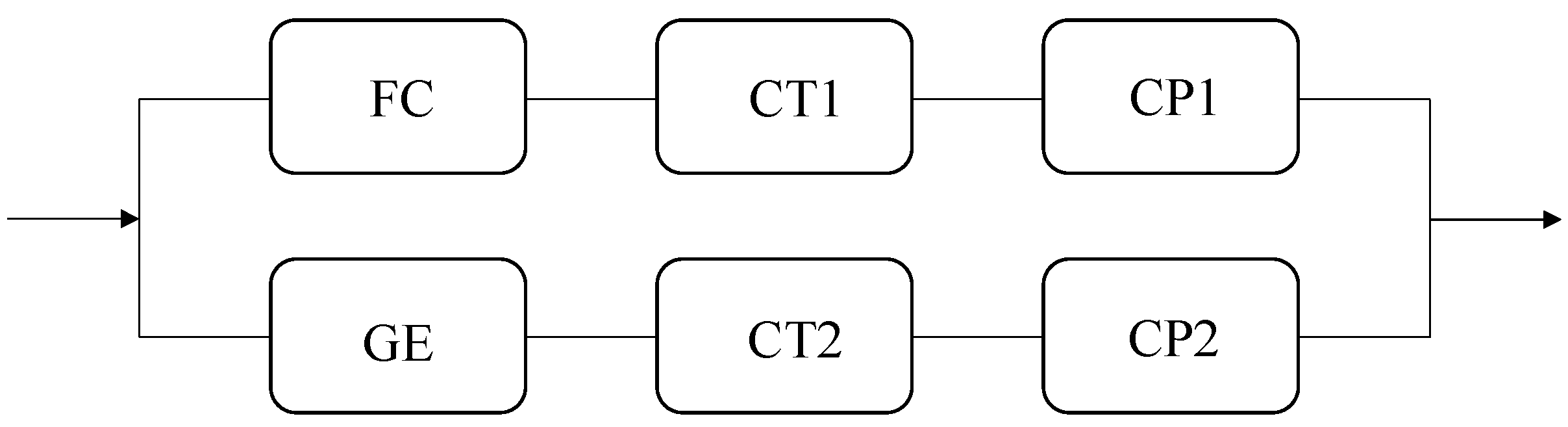
The subsystem of electricity generation of the CCHP system of KSRP consisted of two generation units, a fuel cell unit (E1) and a gas engine unit (E2). The main components of the electricity subsystem of the CCHP system are presented in Table 5. The main components of the fuel cell unit included the fuel cell, cooling power1, and cooling pump1. The main components of the gas engine unit included the gas engine, cooling tower2, and cooling pump2.
A simplified reliability block diagram of the electricity subsystem of the CCHP system is shown in Figure 5. Generally, the two generation units were regarded as having a parallel relationship, where at least one of them would be functioning, and the system was considered reliable and available. However, when one of the units failed, it caused the electricity supply to be in a lacking state. Thus, the situation where one of the units failed was considered as unavailable or partially available. The reliability of the whole system or a subsystem of the CCHP system was defined as all of the components of the system functioning under given conditions for the stated period. This system, considering customer-oriented reliability, could be described as all subsystems were reliable since the system can be viewed as a series system.
Based on reliability analysis methods introduced in 
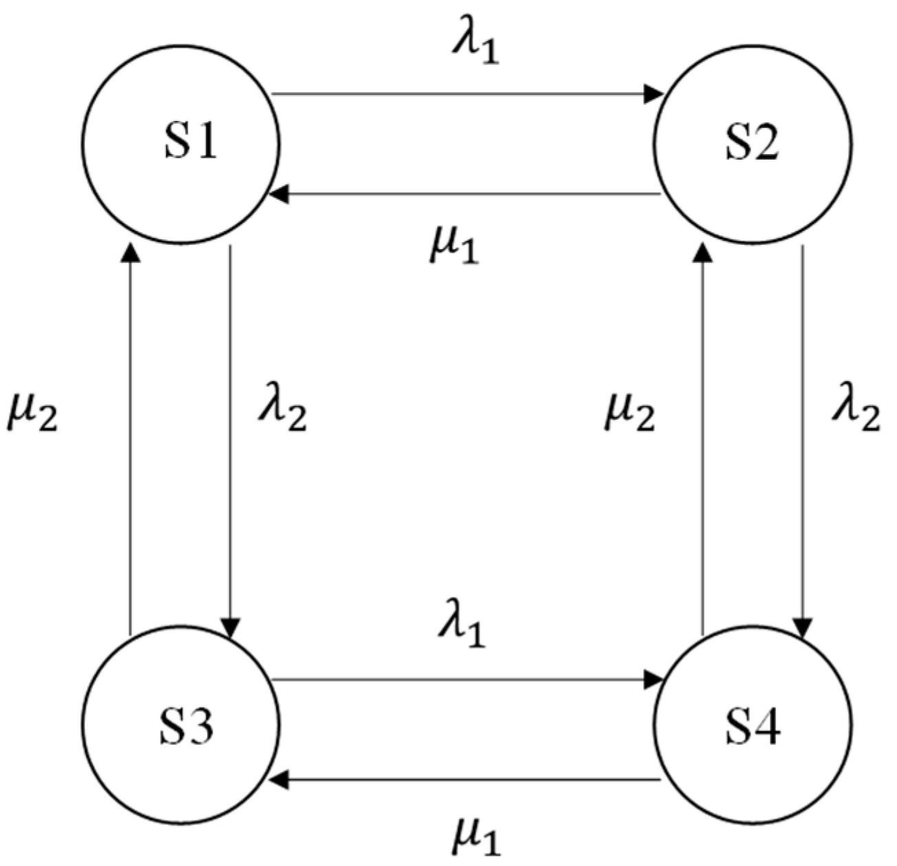
Section 3.1, the operation states and reliability data for the electricity subsystem of the CCHP system is shown in Table 6. The operation states of the electricity subsystem included 4 states, the completely available state (State1), the partially available states (State2, State3), and the completely unavailable state (State4). The failure rate and repair rate of E1, E2, and the subsystems are symbolized in Table 6. The reliability of the electricity subsystem was dependent on the reliability of State1, thus, the reliability of the electricity subsystem was determined by both E1 and E2.
A series system’s reliability was expressed by Equation (14), thus, the reliability of E1 is presented as follows:
R E 1 = R F C R C T 1 R C P 1
A reliability can be expressed by the failure rate as in the following equation:
R k ( t ) = R t λ k ( t )
Therefore, if the failure rates are constant, then Equation (24) can be expressed as
R E 1 = e λ E 1 = e λ F C e λ C T 1 e λ C P 1 = e ( λ F C + λ C T 1 + λ C P 1 )
Thus, the following equation is obtained from the above equation:
λ E 1 = λ F C + λ C T 1 + λ C P 1
Similarly, the failure rate of E2 is obtained using
λ E 2 = λ G E + λ C T 2 + λ C P 2
Moreover, the availability of the electricity subsystem is equal to the probability of State1, and it also is defined as μ / λ + μ , therefore, the availability of the electricity subsystem is expressed as
A e l e c t r i c i t y = μ e l e c t r i c i t y λ e l e c t r i c i t y + μ e l e c t r i c i t y = μ E 1 μ E 2 ( λ E 1 + μ E 1 ) ( λ E 2 + μ E 2 )
Therefore, the repair rate of the electricity system is solved as
μ e l e c t r i c i t y = λ e l e c t r i c i t y μ E 1 μ E 2 λ E 1 λ E 2 + λ E 1 μ E 2 + λ E 2 μ E 1
Let   r E 1 = 1 / μ E 1 , r E 2 = 1 / μ E 2 , r e l e c t r i c i t y = 1 / μ e l e c t r i c i t y , and then
r e l e c t r i c i t y = 1 λ E 1 + λ E 2 ( λ E 1 r E 1 + λ E 2 r E 2 + λ E 1 λ E 2 r E 1 r E 2 )
Usually, μ E 1 λ E 1 , μ E 2 λ E 1 and then, Equation (32) is written as
r e l e c t r i c i t y 1 λ E 1 + λ E 2 ( λ E 1 r E 1 + λ E 2 r E 2 )
Thus, the repair rate of the electricity subsystem is obtained by the following:
μ e l e c t r i c i t y = 1 r e l e c r i c i t y = λ E 1 + λ E 2 λ E 1 μ E 1 + λ E 2 μ E 2
Hence, for a series system consisting of n components, the failure rate and repair rate are presented as the following, respectively:
λ n = k = 1 n λ k
μ n = k = 1 n λ k k = 1 n λ k μ k
Thus, the main reliability parameters of E1, E2, and the electricity subsystem are expressed as the following:
Failure rate of E1:
λ E 1 = λ F C + λ C T 1 + λ C P 1
Failure rate of E2:
λ E 2 = λ G E + λ C T 2 + λ C P 2
Failure rate of electricity subsystem:
λ e l e c t r i c i t y = λ F C + λ C T 1 + λ C P 1 + λ G E + λ C T 2 + λ C P 2
Repair rate of E1:
μ E 1 = λ F C + λ C T 1 + λ C P 1 λ F C μ F C + λ C T 1 μ C T 1 + λ C P 1 μ C P 1
Repair rate of E2:
μ E 2 = λ G E + λ C T 2 + λ C P 2 λ G E μ G E + λ C T 2 μ C T 2 + λ C P 2 μ C P 2
Repair rate of electricity subsystem:
μ e l e c t r i c i t y = λ F C + λ C T 1 + λ C P 1 + λ G E + λ C T 2 + λ C P 2 λ F C μ F C + λ C T 1 μ C T 1 + λ C P 1 μ C P 1 + λ G E μ G E + λ C T 2 μ C T 2 + λ C P 2 μ C P 2
The availability of the electricity subsystem:
A e l e c t r i c i t y = 1 ( λ F C μ F C + λ C T 1 μ C T 1 + λ C P 1 μ C P 1 + λ G E μ G E + λ C T 2 μ C T 2 + λ C P 2 μ C P 2 ) + 1
The reliability of the electricity subsystem:
R e l e c t r i c i t y = R s 1 = e λ e l e c t r i c i t y

4.2. Space Cooling and Heating Subsystem

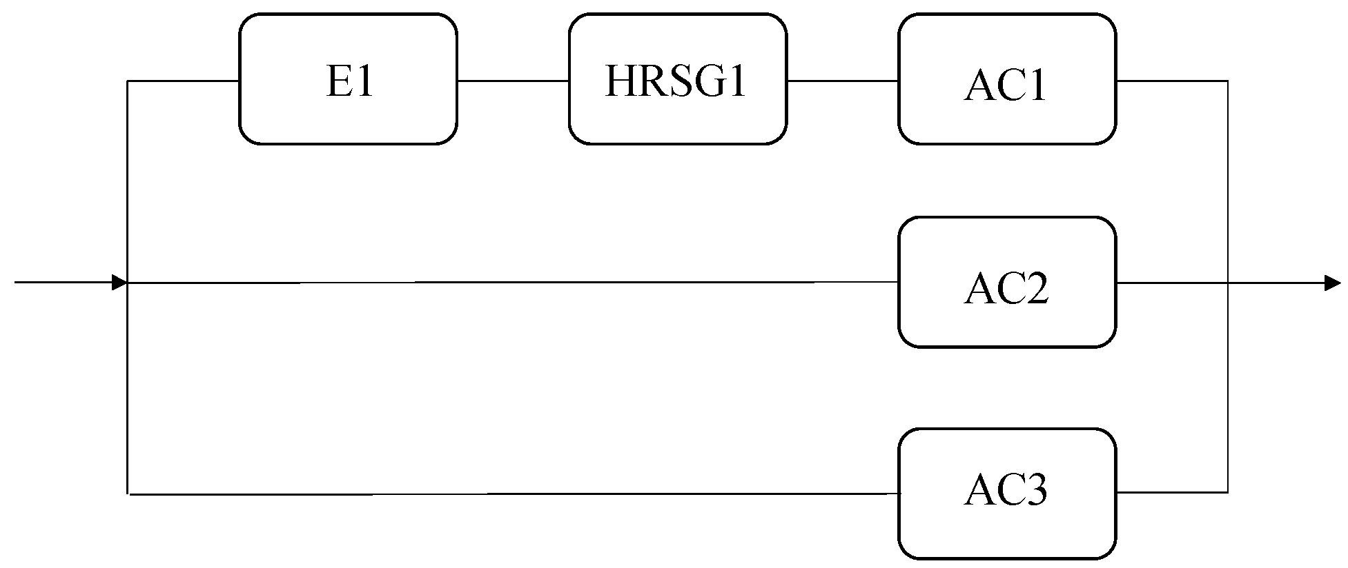
The space cooling and heating subsystem of the CCHP system at KSRP consisted of three space cooling and heating generation units, the generation units that used the waste heat from the fuel cell unit (CH1), and the generation units that assisted the absorption chiller fueled by natural gas (CH2 and CH3). More details of the space cooling and heating subsystem are shown in Table 7. The main components of CH1 included the fuel cell unit (E1), the heat recovery steam generator1, and the absorption chiller1. CH2 and CH3 only had one component, an absorption chiller fueled by natural gas.
A simplified reliability block diagram of the space cooling and heating subsystem of the CCHP system is shown in Figure 6. The space cooling and heating for customers came from three ways. The CH2 and CH3 each used the same component. The operation states and reliability data for the space cooling and heating subsystem of the CCHP system are presented in Table 8. Due to CH2 and CH3 only having one component, the failure rate and repair rate of CH2 and CH3 units were expressed by the component’s failure rate and repair rate. The reliability and availability of the space cooling and heating subsystem were equal to the reliability and availability of State 1.
According to Equations (34) and (35), the main reliability parameters of the CH1 unit and space cooling and heating subsystem are expressed as the following:
Failure rate of CH1:
λ C H 1 = λ E 1 + λ H R S G 1 + λ A C 1
Repair rate of CH1:
μ C H 1 = λ E 1 + λ H R S G 1 + λ A C 1 λ E 1 μ E 1 + λ H R S G 1 μ H R S G 1 + λ A C 1 μ A C 1
Failure rate of the space cooling and heating subsystem:
λ c o o l i n g   &   h e a t i n g = λ E 1 + λ H R S G 1 + λ A C 1 + λ A C 2 + λ A C 3
Repair rate of the space cooling and heating subsystem:
μ c o o l i n g   &   h e a t i n g = λ C H 1 + λ A C 2 + λ A C 3 λ C H 1 μ C H 1 + λ A C 2 μ A C 2 + λ A C 3 μ A C 3
The availability of the space cooling and heating subsystem:
A c o o l i n g   &   h e a t i n g = 1 ( λ C H 1 μ C H 1 + λ A C 2 μ A C 2 + λ A C 3 μ A C 3 ) + 1
The reliability of the space cooling and heating subsystem:
R c o o l i n g   &   h e a t i n g = e λ c o o l i n g   &   h e a t i n g

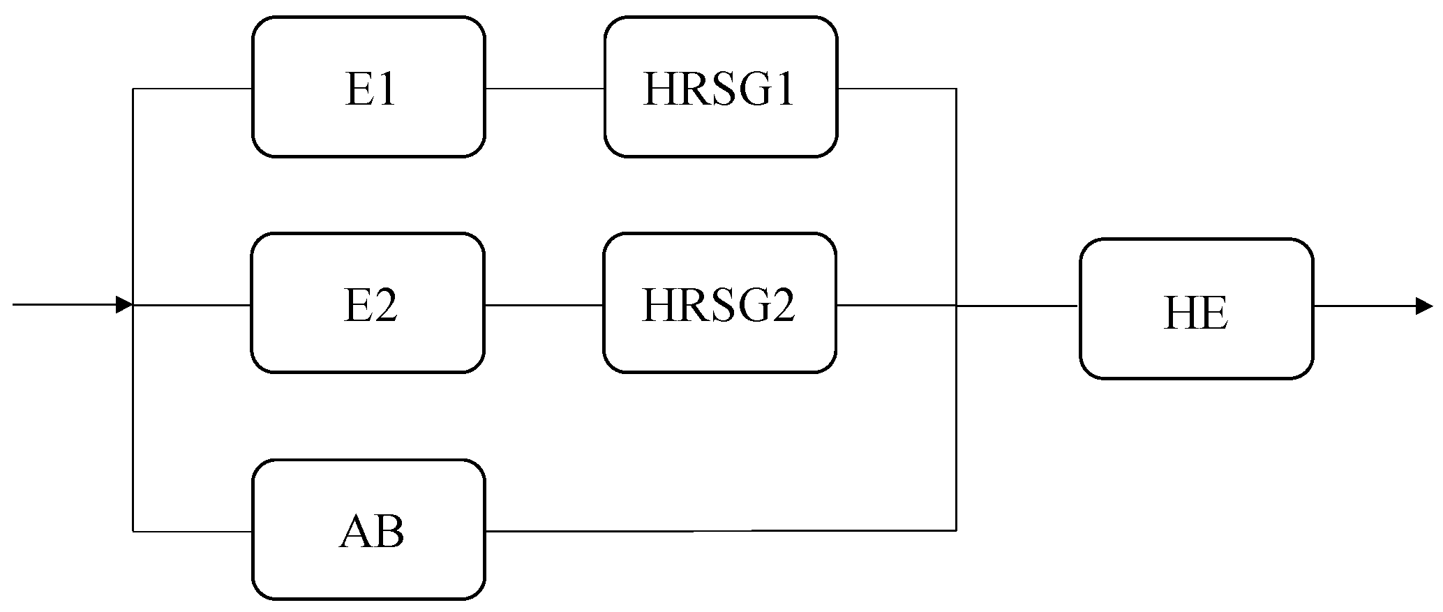
4.3. Hot Water Subsystem

The hot water subsystem of the CCHP system at KSRP consisted of three hot water generation units and a heat exchanger unit. The generation unit (HW1) used the recovery heat from E1, the generation unit (HW2) used the recovery heat from E2, and an auxiliary boiler (HW1) fueled by natural gas produced the hot water when the heat from HW1 and HW2 was not enough. A heat exchanger unit (HE) was used to exchange the heat to hot water. More details of the main components of the hot water subsystem are shown in Table 9. The main components of HW1 included the fuel cell unit and heat recovery steam generator1. The main components of HW2 included the gas engine unit and heat recovery steam generator2, while HW3 had only one component, the auxiliary boiler.
A simplified reliability block diagram of the hot water subsystem of the CCHP system is shown in Figure 7. The hot water subsystem was regarded as a series system consisting of the three hot water generation units and a heat exchanger unit. When the heat exchanger unit failed, the hot water supply was interrupted and the hot water subsystem was unavailable. The operation states and reliability data for the hot water subsystem of the CCHP system is shown in Table 10. There were 9 states of the hot water subsystem. The reliability and availability of the hot water subsystem were equal to the reliability and availability of State1. Thus, the main reliability parameters of HW1, HW2, and the hot water subsystem were obtained as follows:
Failure rate of HW1:
λ H W 1 = λ E 1 + λ H R S G 1
Repair rate of HW1:
μ H W 1 = λ E 1 + λ H R S G 1 λ E 1 μ E 1 + λ H R S G 1 μ H R S G 1
Failure rate of HW2:
λ H W 2 = λ E 2 + λ H R S G 2
Repair rate of HW2:
μ H W 2 = λ E 2 + λ H R S G 2 λ E 2 μ E 2 + λ H R S G 2 μ H R S G 2
Failure rate of the hot water subsystem:
λ h o t   w a t e r = λ H W 1 + λ H W 2 + λ A B + λ H E
Repair rate of the hot water subsystem:
μ h o t   w a t e r = λ H W 1 + λ H W 2 + λ A B + λ H E λ H W 1 μ H W 1 + λ H W 2 μ H W 2 + λ A B μ A B + λ H E λ H E
The availability of the hot water subsystem:
A h o t   w a t e r = 1 ( λ H W 1 μ H W 1 + λ H W 2 μ H W 2 + λ A B μ A B + λ H E λ H E ) + 1
The reliability of the hot water subsystem:
R hot   water = e λ h o t   w a t e r

5. Numerical Calculation and Discussion

The numerical calculation and analysis of the CCHP system at KSRP is discussed in this section. All the base reliability data (failure rate, MTTR and so forth.) were obtained from actual records, such as operation records, maintenance records, repair records, and more.

5.1. Reliability Calculation

Based on the actual investigation, the failure rate and MTTR of the main components of the CCHP system at KSRP are shown in Table 11. The failure rate and MTTR were the actual data gathered from inspection and repair records of the CCHP system at KSPR from April 2002 to March 2011. During this investigation, the repair data of the cooling pumps of the cooling water system, the heat recovery steam generators, and the absorption chillers were difficult to separate because the same components were maintained and repaired at the same time, generally. Therefore, the three components assumed the same failure rate and MTTR even though they were in different generation units. The failure rate and MTTR of the tree type components were obtained based on the total number of failures and the number of components. Table 11 shows that the gas engine had the highest failure rate and that the fuel cell had the second highest failure rate, thus, the power generation unit had a higher failure rate than other units. The auxiliary boiler and heat exchanger had the lowest failure rate. The fuel cell and absorption chiller had the highest MTTR in this system. All the reliability data were a true reflection of the actual situation of the system under the current operation and maintenance strategies. Each component had an independent maintenance strategy according to the manufacturer’s recommendations.
The reliability and availability of the CCHP system at KSRP was analyzed in Section 3.1. Based on that analysis, the calculation results are present here. The reliability of all components in the CCHP system is shown in Figure 8. The reliability of each component was related to failure rate. The reliability of the electricity generator and absorption chiller was lower than other components in this system, and the heat exchanger and auxiliary boiler had the higher reliability.
The reliability of the electricity, space cooling and heating, and hot water generation units are shown in Figure 9. Comparing the reliability of two electricity generation units, the fuel cell unit was higher than the gas engine unit because the gas engine had a higher failure rate than the fuel cell, while the cooling water system’s failure rates were similar. The reliability of the space cooling and heating generation unit (CH1) that combined with the waste heat recovery unit was lower than the reliability of the generation units, which only had the gas-fired absorption chiller. Comparing the three hot water generation units, the reliability of the hot water generation units (HW1, HW2), which combined with the waste heat recovery unit, were lower than the reliability of the auxiliary boiler. Figure 10 and Figure 11 show the reliability and availability of the subsystems and the whole system. The space cooling and heating system was more unreliable than other subsystems because the absorption chiller’s reliability was lower. The results show that the reliability of the CCHP system depended on each component’s reliability due to it being a series system.

5.2. Component Importance Calculation

The Birnbaum importance (BI) and criticality importance (CI) methods were applied in this system to evaluate the subsystem and components’ importance levels over the whole system and to give a maintenance prioritization of components within this system. Simultaneously, the failure cost importance index (FCI) described in Section 3.2 was calculated in this section, and the results of the failure cost reliability importance are compared to BI and CI.
The BI values of the components of the CCHP system are shown in Figure 12. The maintenance prioritization of the components using the BI values is GE > AC > FC > CP2 > CP1 > HRSG1 > HRSG2 > CT1 > CT2 > AB > HE. The reliability importance of the power generation unit and absorption chiller was higher than the other components. Figure 13 shows the CI values of the components of the CCHP system. The order of the priority maintenance actions is the same as the BI analysis results. However, the criticality importance of the gas engine is much larger than other components, for instance, the cooling pump, cooling tower, auxiliary boiler, heat exchanger, and heat recovery steam generator.
The failure cost importance indices were introduced in Section 3.2. The failure cost includes the repair cost of the failure component and the cost of the outage due to component failure. The cost of outage can be calculated by Equation (21), and the outage data of electricity, space cooling and heating, and hot water due to the component failure is shown in Table 12. The failure of the fuel cell unit (E1) led to the outage of electricity, space cooling and heating, and hot water. The failure of the gas engine led to the outage of electricity and hot water. Since AC2 and AC3 do not use waste heat, their failure can be equated to no added cost of failure. The repair cost of each component is calculated according to the actual data from April 2002 to March 2011.
The failure cost importance index values of the components of the CCHP system are shown in Figure 14. The order of prioritized maintenance is GE > HRSG2 > HRSG1 > FC > AB > HE > CT1 > CT2 > CP > AC. The gas engine had the higher failure cost than other components. The failure cost of the absorption chiller was lowest in the CCHP system. Potential failure cost importance index values of the components of the CCHP system are presented in Figure 15. This result shows the potential failure cost before the failure occurred. It presents the importance of the component maintenance from the perspective of operation and maintenance costs. The order of prioritized maintenance based on potential failure cost importance index values is GE > FC > AC > HRSG2 > HRSG1 > CP > CT1 > CT2 > AB > HE. Comparing the failure cost importance index and potential failure cost importance index, the gas engine was the most important component of this CCHP system. The reliability importance of the fuel cell and heat recovery steam generator were second in importance to the gas engine. The difference between the failure cost importance index and the potential failure cost importance is that the failure rate is considered in the potential failure cost importance. The auxiliary boiler and heat exchanger, for instance, had the highest failure cost of one component, but had the lowest potential failure cost due to the low failure rate. This point should be considered in the system design and maintenance strategies.
The four reliability importance indices have been applied in this system, and the results are presented. Comparing the four reliability importance indices, the BI and CI were only related to the failure rate, generally, which can be reduced by improving the maintenance level and optimizing the maintenance strategy for repairs of a complex system. Reducing the system operation and maintenance costs is one of the main goals of maintenance optimization. Thus, the reliability importance indices that consider the repair and outage costs were applied to assess the priority of component maintenance within the system. The failure cost importance index was related to the MTTR and the repair cost of each component. The potential failure cost importance index was not only related to the MTTR and repair cost, but to the failure rate. Therefore, the failure cost importance and potential failure cost importance indices can provide a comprehensive analysis measure for the component maintenance optimization.

6. Conclusions and Prospects

This paper focuses on the reliability and availability analysis and components maintenance prioritization analysis of the CCHP system. Failure cost importance index (FCI) and potential failure cost importance index (PI) were developed for the maintenance prioritization analysis of the CCHP system. A Markov model based on a state–space method was used to analyze the reliability and availability of the CCHP system. The reliability and availability of the components, subsystems, and whole system were deduced.
This paper aimed at selecting the component reliability importance indices to identify the priority of the component maintenance from the perspective of maintenance cost. The BI and CI were used to compare to FCI and PI. It was observed that the FCI and PI might lead to different rankings. FCI enabled the system managers to know the cost of a one-time failure of each component in a system. PI enabled the system managers to know the cost before the failure occurred for a one-time failure of each component in a system. The two indices would help managers to make a reasonable decision for maintenance on the cost basis, and also help designers to optimize the system on the cost basis.
The reliability of the CCHP system is the product of the reliability of each component when the reliability is considered the energy supply. The system reliability can be ensured by improving the components’ failure rates. The auxiliary boiler (low failure rate with high failure cost) can improve the reliability of the subsystem.
The reliability and availability analysis method is the only study on how one component failure can affect the system as a whole or in part; the reliability of multiple failure states and the time-variances were ignored. Moreover, the CCHP system is a complex and repairable system, generally with high maintenance and reliability, where failure data is difficult to obtain, thus, the degradation data can be used to optimize the maintenance strategy based on the component reliability importance indices.
The proposed component reliability importance indices of the maintenance prioritization analysis in this paper can be applied to other cogeneration systems or to other maintenance problems. The reliability importance indices will be further validated in CCHP systems which use renewable energies and other technologies like PV, wind power, or heat pumps.

Author Contributions

J.J. analysis the data and wrote paper; Z.L. contributed materials; X.W., W.G. and S.K. provided revised suggestions and editing.

Conflicts of Interest

The authors declare no conflict of interest.

Abbreviations

Nomenclature
CCHPCombined cooling heating and power
SSMState-space method
KSRPKitakyushu science and research park
RReliability
AAvailability
UUnavailability
PProbability
fNumber of failure
λ Failure rate (f/unit time)
μ Repair rate
eNapier’s constant
MTBFMean time between failure
MTTFMean time to failure
MTTRMean time to repair
tTime
uUnit price of grid electricity or city gas
L u Purchases of electricity or city gas
I Importance index
BIBirnbaum importance
CICriticality importance
FCIFailure cost importance index
PIPotential failure cost importance index
C T F Total failure cost (total cost/unit time)
C R Repair cost
C A Add cost during outage
JPYJapanese yen
Subscript
sysSystem
kComponent number
i, jNumber of state
nFailure numbers of one component in a certain period
Superscript
BBirnbaum importance index
CCriticality importance index
FFailure cost importance index (cost/f)
PPotential failure cost importance index (cost/unit time)
Main units and components
EGeneration unit of electricity
CHGeneration unit of space cooling and heating
HWGeneration unit of hot water
FCFuel cell
GEGas engine
CTCooling tower
CPCooling pump
HRSGHeat recovery steam generator
ACAbsorption chiller
ABAuxiliary boiler
HEHeat exchanger
CWSCooling water system
ACSAbsorption chiller system

References

  1. Gu, W.; Wu, Z.; Bo, R.; Liu, W.; Zhou, G.; Chen, W.; Wu, Z. Modeling, planning and optimal energy management of combined cooling, heating and power microgrid: A review. Int. J. Electr. Power Energy Syst. 2014, 54, 26–37. [Google Scholar] [CrossRef]
  2. Cho, H.; Smith, A.D.; Mago, P. Combined cooling, heating and power: A review of performance improvement and optimization. Appl. Energy 2014, 136, 168–185. [Google Scholar] [CrossRef]
  3. Wang, J.; Zhai, Z.J.; Zhang, C.; Jing, Y. Environmental impact analysis of BCHP system in different climate zones in China. Energy 2010, 35, 4208–4216. [Google Scholar] [CrossRef]
  4. Schepp, C. Assessing Combined Cooling, Heating and Power Systems in Northeast Wisconsin; Energy Center of Wisconsin: Madison, WI, USA, 2002. [Google Scholar]
  5. Liu, M.; Shi, Y.; Fang, F. Combined cooling, heating and power systems: A survey. Renew. Sustain. Energy Rev. 2014, 35, 1–22. [Google Scholar] [CrossRef]
  6. Lo Basso, G.; Nastasi, B.; Salata, F.; Golasi, I. Energy retrofitting of residential buildings—How to couple Combined Heat and Power (CHP) and Heat Pump (HP) for thermal management and off-design operation. Energy Build. 2017, 151, 293–305. [Google Scholar] [CrossRef]
  7. El-Khattam, W.; Salama, M.M.A. Distributed generation technologies, definitions and benefits. Electr. Power Syst. Res. 2004, 71, 119–128. [Google Scholar] [CrossRef]
  8. Ou, T.-C. Design of a Novel Voltage Controller for Conversion of Carbon Dioxide into Clean Fuels Using the Integration of a Vanadium Redox Battery with Solar Energy. Energies 2018, 11, 524. [Google Scholar] [CrossRef]
  9. Li, G.; Wang, R.; Zhang, T.; Ming, M. Multi-Objective Optimal Design of Renewable Energy Integrated CCHP System Using PICEA-g. Energies 2018, 11, 743. [Google Scholar]
  10. Chen, Y.; Wang, Y.; Ma, J. Multi-Objective Optimal Energy Management for the Integrated Electrical and Natural Gas Network with Combined Cooling, Heat and Power Plants. Energies 2018, 11, 734. [Google Scholar] [CrossRef] [Green Version]
  11. Wang, F.; Zhou, L.; Ren, H.; Liu, X. Search Improvement Process-Chaotic Optimization-Particle Swarm Optimization-Elite Retention Strategy and Improved Combined Cooling-Heating-Power Strategy Based Two-Time Scale Multi-Objective Optimization Model for Stand-Alone Microgrid Operation. Energies 2017, 10, 1936. [Google Scholar] [CrossRef]
  12. Jing, Y.-Y.; Bai, H.; Wang, J.-J.; Liu, L. Life cycle assessment of a solar combined cooling heating and power system in different operation strategies. Appl. Energy 2012, 92, 843–853. [Google Scholar] [CrossRef]
  13. Hara, E.; Gao, W.; Ojima, T. Study on Estimate Formulae of Maintenance Cost and Evaluation Method of Renewal Period on Air Conditioning System in Office building. J. Archit. Plan. Environ. Eng. AIJ 2001, 547, 209–214. [Google Scholar] [CrossRef]
  14. Ou, T.-C. A novel unsymmetrical faults analysis for microgrid distribution systems. Int. J. Electr. Power Energy Syst. 2012, 43, 1017–1024. [Google Scholar] [CrossRef]
  15. Ou, T.-C.; Hong, C.-M. Dynamic operation and control of microgrid hybrid power systems. Energy 2014, 66, 314–323. [Google Scholar] [CrossRef]
  16. Ou, T.-C.; Lu, K.-H.; Huang, C.-J. Improvement of Transient Stability in a Hybrid Power Multi-System Using a Designed NIDC (Novel Intelligent Damping Controller). Energies 2017, 10, 488. [Google Scholar] [CrossRef]
  17. Noussan, M.; Jarre, M. Multicarrier energy systems: Optimization model based on real data and application to a case study. Int. J. Energy Res. 2018, 42, 1338–1351. [Google Scholar] [CrossRef]
  18. Zamani-Gargari, M.; Kalavani, F.; Abapour, M.; Mohammadi-Ivatloo, B. Reliability assessment of generating systems containing wind power and air separation unit with cryogenic energy storage. J. Energy Storage 2018, 16, 116–124. [Google Scholar] [CrossRef]
  19. Yang, H.; Wang, L.; Zhang, Y.; Qi, X.; Wang, L.; Wu, H. Reliability Assessment of Wind Farm Electrical System Based on a Probability Transfer Technique. Energies 2018, 11, 744. [Google Scholar] [CrossRef]
  20. Wang, J.-J.; Fu, C.; Yang, K.; Zhang, X.-T.; Shi, G.-H.; Zhai, J. Reliability and availability analysis of redundant BCHP (building cooling, heating and power) system. Energy 2013, 61, 531–540. [Google Scholar] [CrossRef]
  21. Haghifam, M.R.; Manbachi, M. Reliability and availability modelling of combined heat and power (CHP) systems. Int. J. Electr. Power Energy Syst. 2011, 33, 385–393. [Google Scholar] [CrossRef]
  22. Frangopoulos, C. Effect of reliability considerations on the optimal synthesis, design and operation of a cogeneration system. Energy 2004, 29, 309–329. [Google Scholar] [CrossRef]
  23. El-Nashar, A.M. Optimal design of a cogeneration plant for power and desalination taking equipment reliability into consideration. Desalination 2008, 229, 21–32. [Google Scholar] [CrossRef]
  24. Sabouhi, H.; Abbaspour, A.; Fotuhi-Firuzabad, M.; Dehghanian, P. Reliability modeling and availability analysis of combined cycle power plants. Int. J. Electr. Power Energy Syst. 2016, 79, 108–119. [Google Scholar] [CrossRef]
  25. Carazas, F.J.G.; De Souza, G.F.M. Availability Analysis of Gas Turbines Used in Power Plants. Int. J. Thermodyn. 2009, 12, 28–37. [Google Scholar]
  26. Catelani, M.; Ciani, L.; Venzi, M. Component Reliability Importance assessment on complex systems using Credible Improvement Potential. Microelectron. Reliabil. 2016, 64, 113–119. [Google Scholar] [CrossRef]
  27. Arya, R. Ranking of feeder sections of distribution systems for maintenance prioritization accounting distributed generations and loads using diagnostic importance factor (DIF). Int. J. Electr. Power Energy Syst. 2016, 74, 70–77. [Google Scholar] [CrossRef]
  28. Pepermans, G.; Driesen, J.; Haeseldonckx, D.; Belmans, R.; D’haeseleer, W. Distributed generation: Definition, benefits and issues. Energy Policy 2005, 33, 787–798. [Google Scholar] [CrossRef]
  29. Kitakyushu Science and Research Park. Available online: https://www.ksrp.or.jp/ (accessed on 8 June 2018).
  30. Ruan, Y.; Gao, W.; Suagara, N.; Ryu, Y. Investigation and Evaluation on District Energy System at Kitakyushu Science and Research Park—Field Study on Running Situation during 2002. J. Asian Archit. Build. Eng. 2005, 4, 237–243. [Google Scholar] [CrossRef]
  31. Marvin Rausand, A.H. System Reliability Theory: Models, Statistical Methods, and Applications; John Wiley & Sons, Inc.: Hoboken, NJ, USA, 2004. [Google Scholar]
  32. Andrew, K.S.; Jardine, A.H.C.T. Maintenance, Replacement, and Reliability: Theory and Applications, 2nd ed.; CRC Press: Boca Raton, FL, USA, 2013. [Google Scholar]
  33. Arabian-Hoseynabadi, H.; Oraee, H.; Tavner, P.J. Failure Modes and Effects Analysis (FMEA) for wind turbines. Int. J. Electr. Power Energy Syst. 2010, 32, 817–824. [Google Scholar] [CrossRef] [Green Version]
  34. Sondalini, M. Plant and Equipment Wellness; Engineers Media: Crows Nest, Australian, 2009. [Google Scholar]
  35. Birnbaum, Z.W. On the importance of different components in a multicomponent system. In Multivariate Analysis-II; Krishnaiah, P.R., Ed.; Academic Press: New York, NY, USA, 1969; pp. 581–592. [Google Scholar]
  36. Bertling, P.H.A.L. A Method for Extracting Reliability Importance Indices from Reliability Simulations of Electrical Networks. In Proceedings of the 15th Power Systems Computation Conference (PSCC 2005), Liège, Belgium, 22–26 August 2005; Session 25. pp. 1–7. [Google Scholar]
  37. Wang, W.; Loman, J.; Vassiliou, P. Reliability Importance of Components in a Complex System. In Proceedings of the Annual Reliability and Maintainability Symposium, Los Angeles, CA, USA, 26–29 January 2004; pp. 6–11. [Google Scholar]
  38. Dev, N.; Samsher; Kachhwaha, S.S.; Attri, R. Development of reliability index for combined cycle power plant using graph theoretic approach. Ain Shams Eng. J. 2014, 5, 193–203. [Google Scholar] [CrossRef]
  39. Hajian-Hoseinabadi, H. Reliability and component importance analysis of substation automation systems. Int. J. Electr. Power Energy Syst. 2013, 49, 455–463. [Google Scholar] [CrossRef]
  40. Gao, R.; Yao, K. Importance Index of Components in Uncertain Reliability Systems. J. Uncertain. Anal. Appl. 2016, 4, 7. [Google Scholar] [CrossRef]
  41. Hilber, P. Component reliability importance indices for electrical networks. In Proceedings of the 8th International Power Engineering Conference (IPEC 2007), Singapore, 3–6 December 2007; pp. 257–263. [Google Scholar]
  42. Garg, A.; Deshmukh, S.G. Maintenance management: Literature review and directions. J. Qual. Maint. Eng. 2006, 12, 205–238. [Google Scholar] [CrossRef]
Figure 1. The system scheme of the CCHP system at KSRP.
Energies 11 01519 g001
Figure 2. The research flowchart of reliability and maintenance prioritization analysis.
Energies 11 01519 g002
Figure 3. The Markov model of a system with two components.
Energies 11 01519 g003
Figure 4. A simple customer-oriented reliability model of a CCHP system.
Energies 11 01519 g004
Figure 5. The reliability block diagram of an electricity subsystem of the CCHP system.
Energies 11 01519 g005
Figure 6. The reliability block diagram of the space cooling and heating subsystem of the CCHP system.
Energies 11 01519 g006
Figure 7. The reliability block diagram of the hot water subsystem of the CCHP system.
Energies 11 01519 g007
Figure 8. The reliability of all components in the CCHP system.
Energies 11 01519 g008
Figure 9. The reliability of the generation units of the CCHP system.
Energies 11 01519 g009
Figure 10. The reliability of the systems of the CCHP system at KSRP.
Energies 11 01519 g010
Figure 11. The availability of the systems of the CCHP system at KSRP.
Energies 11 01519 g011
Figure 12. The BI values of the components of the CCHP system.
Energies 11 01519 g012
Figure 13. The CI values of the components of the CCHP system.
Energies 11 01519 g013
Figure 14. The failure cost importance index values of components of the CCHP system.
Energies 11 01519 g014
Figure 15. The potential failure cost importance index values of components of the CCHP system.
Energies 11 01519 g015
Table 1. The main components of the CCHP system technologies.
TechnologyFunctionMain Components/Subsystems
Fuel cell (FCs)Power generation;
Waste heat supply
Fuel processor, air processor, power section, power conditioner and so forth.
Reciprocating enginesPower generation;
Waste heat supply
Engine, fuel processor, generator, cooling system, and so forth.
Gas turbines/enginesPower generation;
Waste heat supply
Engine/turbine, generator, compressor, fuel compressor, power conditioner, cooling system, and so forth.
Photovoltaic system (PVs)Power generationSolar cells, power conditioner, DC/AC generator and so forth.
Wind energy conversion system (WECS)Power generationWinder turbines, generator, gearbox, yaw motor and so forth.
Small hydro-turbinesPower generationTurbine, generator, power conditioner and so forth.
BoilerThermal supplyBurner, heat exchanger, supply lines, return lines, firebox, circulator pumps, deaerators/condenser and so forth.
Absorption chillerThermal supplyThermal compressor, condenser, evaporator, cooling tower, solution pump and so forth.
Heat pumpThermal supplyCompressor, condenser, expansion valve, evaporator and so forth.
Table 2. The details of the power generation units of the CCHP system at KSRP.
TypeFuel CellGas Engine
Capacity200 kW160 kW
Power generation efficiency (with 100% load)40%28.7%
Heat release efficiency (with 100% load)20%, Collecting heat for hot water47.7%
Collecting heat for hot water
20%, Collecting heat for space cooling and heating
Operational modeRun for 24 h over timeRun for 14 h
Priority to runRun for 8:00~22:00
Table 3. The possible states of a system with two components.
ItemsComponent 1Component 2
Failure rate λ 1 λ 2
Repair rate μ 1 μ 2
State 111
State 201
State 310
State 400
There are two states for every component: a functioning state (1) and a failed state (0).
Table 4. The comparisons of the component reliability importance indices.
Importance IndexDescriptionRelation of Maintenance Factors
I B The probability of a component failing at time tFailure rate
I C The probability of a component failing before time tFailure rate
I F The expect failure cost if the component fails.Repair rate, component repair cost.
I P The expect failure cost in a unit time caused by component failure.Failure rate, repair rate, component repair cost.
Table 5. The electricity subsystem of CCHP system.
Generation Unit of ElectricityMain ComponentFunction
E1Fuel cell (FC), Cooling tower1 (CT1), and Cooling pump1 (CP1).Produce electricity
E2Gas engine (GE), Cooling tower2 (CT2), and Cooling pump2 (CP2).Produce electricity
Table 6. The operation states and reliability data for the electricity subsystem of the CCHP system.
ItemsE1E2Electricity SupplyState Reliability
Failure rate λ E 1 λ E 2 λ e l e c t r i c i t y ----
Repair rate μ E 1 μ E 2 μ e l e c t r i c i t y ----
State 111E1 + E2 R E 1 R E 2
State 201E2 (lacking) R E 2
State 310E1 (lacking) R E 1
State 40000
Table 7. The space cooling and heating subsystem of the CCHP system.
Generation Unit of Cooling and HeatingMain EquipmentFunction
CH1Fuel cell unit (E1), Heat recovery steam generator1 (HRSG1), Absorption chiller 1 (AC1).Supply cooling or heating by using the heat from heat recovery steam generator 1
CH2Absorption chiller 2 (AC2).Supply heating or cooling using natural gas
CH3Absorption chiller 3 (AC3).Supply heating or cooling using natural gas
Table 8. The operation states and reliability data for the space cooling and heating subsystem of the CCHP system.
ItemsCH1CH2CH3Space Cooling and Heating SupplyState Reliability
Failure rate λ C H I λ A C 2 λ A C 3 λ c o o l i n g   &   h e a t i n g ----
Repair rate μ C H 1 μ A C 2 μ A C 3 μ c o o l i n g   &   h e a t i n g ----
State 1111 CH 1 + CH 2 + CH 3 R CH 1 R CH 2 R CH 3
State 2101 CH 1 + CH 3   (lacking) R CH 1 R CH 3
State 3110 CH 1 + CH 2   (lacking) R CH 1 R CH 2
State 4100 CH 1   (lacking) R CH 1
State 5011 CH 2 + CH 3   (lacking) R CH 2 R CH 3
State 6010 CH 2   (lacking) R CH 2
State 7001 CH 3   (lacking) R CH 3
State 800000
Table 9. The hot water subsystem of the CCHP system.
Generation Unit of Hot WaterMain EquipmentFunction
HW1Fuel cell unit (E1), Heat recovery steam generator 1. (HRSG1)Supply heat for hot water from HRSG1
HW2Gas engine unit (E2), Heat recovery steam generator 2 (HRSG2).Supply heat for hot water from HRSG2.
HW3Auxiliary boiler (AB).Supply heat for hot water using natural gas.
HEHeat exchanger (HE).Exchanged the heat for hot water.
Table 10. The operation states and reliability data for the hot water subsystem of the CCHP system.
ItemsHW1HW2HW3HEHot Water SupplyState Reliability
Failure rate λ H W 1 λ H W 2 λ A B λ H E λ H o t   w a t e r ----
Repair rate μ H W 1 μ H W 2 μ A B μ H E μ H o t   w a t e r ----
State 11111 H W 1 + H W 2 + H W 3 R H W 1 R H W 2 R H W 3 R H E
State 21101 H W 1 + H W 2 (lacking) R H W 1 R H W 2 R H E
State 31011 H W 1 + H W 3 (lacking) R H W 1 R H W 3 R H E
State 40111 H W 2 + H W 3 (lacking) R H W 2 R H W 3 R H E
State 51001 H W 1 (lacking) R H W 1 R H E
ate 60101 H W 2 (lacking) R H W 2 R H E
State 70011 H W 3 (lacking) R H W 3 R H E
State 8000100
State 9111000
Table 11. The failure rate and MTTR of the main component of the CCHP system in KSRP.
Main ComponentsComponent SymbolFailure Rate (Failure/Day)MTTR (Days)
Fuel CellFC0.0029822.0
Cooling tower for fuel cellCT10.0012101.0
Cooling pump for fuel cellCP10.0015341.0
Gas engineGE0.0080371.4
Cooling tower for gas engineCT20.0011431.0
Cooling pump for gas engineCP20.0015341.0
Heat recovery steam generator for fuel cellHRSG10.0012171.5
Heat recovery steam generator for gas engineHRSG20.0012171.5
Absorption chillerAC1 to 30.0052652.0
Auxiliary boilerAB0.0009301.0
Heat exchangerHE0.0008461.0
Table 12. The outage data of electricity, space cooling and heating, and hot water due to component failure.
Main ComponentComponent SymbolOutage
Electricity (kWh/day)Hot Water (kWh/Day)Heat/Cooling (kWh/Day)
Fuel CellFC480022802280
Cooling tower for fuel cellCT1480022802280
Cooling pump for fuel cellCP1480022802280
Heat recovery steam generator for fuel cellHRSG1---22802280
Gas engineGE16002520---
Cooling tower for gas engineCT216002520---
Cooling pump for gas engineCP216002520---
Heat recovery steam generator for gas engineHRSG2---2520---
Absorption chillerAC1------2280
AC2---------
AC3---------
Auxiliary boilerAB---463---
Heat exchangerHE---5263---

