1. Introduction
With the advancement in technologies being used underwater, there has been massive increase in research activities related to underwater wireless sensor networks (UWSNs) by both academia and industry [
1,
2,
3]. They are comprised of sensor nodes and sink(s) that are deployed on the seabed through ships. The deployed sensor nodes transmit the sensed data to the sink through a specific routing mechanism [
2,
4,
5,
6,
7]. UWSNs are used as substitutes to traditional exploration and monitoring of oceans. Many applications such as harvesting renewable energy, environmental monitoring, oceanographic data collection, and exploration of underwater hidden resources require proper infrastructure and timely maintenance. The high-pressure underwater environment restricts human ability to work there for a long time. Terrestrial Wireless Sensor Networks (TWSNs) is a well-researched area with many routing strategies to choose from. The traditional method of using radio signals for communication in TWSNs cannot be applied in UWSNs because these signals are heavily attenuated in the aqueous environment. Thus, acoustic signals are widely used for such purposes, as they have a low absorption rate and are feasible for underwater communications [
7,
8,
9,
10].
The network topology of UWSNs is dynamic i.e., the nodes’ position keeps changing due to change in water current [
5,
6,
11]. Furthermore, maintaining the network lifetime in UWSNs is challenging because the sensor nodes are powered by the batteries that cannot be replaced after underwater deployment.
In a nutshell, existing routing protocols for TWSNs cannot work for UWSNs due to long propagation delay, high mobility, limited bandwidth, energy-constraint and non-uniform topology structure caused by the node movement. Many routing protocols have been proposed for UWSNs. Some of these maximize the network lifetime on the cost of throughput and some improves throughput by compromising on packet delay [
6]. Among these protocols, clustering is reported as a best technique for load balancing in UWSNs where sensor nodes are arranged in multiple groups. These groups are headed by one sensor node known as a cluster head [
6,
11,
12,
13]. Similarly, the use of a mobile sink has been observed as an efficient way of improving throughput [
14,
15]. Mobile sinks can visit each sensor node individually or the entire cluster to gather data.
In [
11], authors employed two mobile sinks to gather data in sparse regions. The throughput of network is affected when both sinks take adjacent positions as they are covering the same sensor nodes [
11,
16]. Recent research proves that the optimum number of mobile sinks with efficient path movement maximizes network performance [
14,
15,
17].
Based on the above discussion, a routing protocol has been proposed that uses two mobile sinks, in a way that they cannot cover the same transmission area. The focus of the proposed scheme is to minimize the packet drop ratio by efficient utilization of mobile sinks. Apart from the routing scheme, a new metric; “Mobile Sink Utility Ratio (MUR)” is also introduced in this paper. MUR represents the data packets collected by the mobile sink to the total packets sent from the sensor nodes in any specific round. The higher value of MUR shows the efficient usage of mobile sinks and vice versa.
The rest of the paper is organized as follows: in
Section 2, related work is discussed.
Section 3 describes the limitations in the sparsity aware energy efficient clustering routing protocol (SEEC) routing scheme.
Section 4 presents the proposed scheme in detail. Performance evaluation of the proposed routing protocol and its comparison with existing routing schemes is discussed in
Section 5. Conclusions and future work is presented in
Section 6.
2. Related Work
Yan et al. presented a location-free depth base routing scheme (DBR) for UWSNs [
7]. In DBR, depth is a selection criteria for the data forwarding node. Sensor nodes send their depth along with sensed data. Nodes with low depth are the one forwarding data. This scheme is suitable for networks where sensor nodes are deployed close to each other. Initially, sensor nodes in DBR are densely deployed; however, due to unbalanced energy consumption, energy holes are created. Energy hole creation degrades the performance of DBR resulting in low throughput.
In [
5], the authors proposed routing protocol called weighting depth and forwarding area division depth base routing protocol (WDFAD-DBR). It reduces the void holes problem and achieves reliability in sparse deployment. The energy consumption is balanced in this protocol through division criteria of forwarding regions. Forwarding regions are divided on the basis of node density and the condition of channel.
In [
11,
16], SEEC is proposed. In SEEC, clustering is implied on dense regions while mobile sinks are sent to a sparse region to gather data. Clustering in dense regions made the protocol energy efficient. The stability period is also increased as compared to an energy efficient depth based routing protocol (EEDBR) [
18]. Mobile sinks in sparse regions are not utilized efficiently, which causes low throughput in SEEC.
In [
19], the authors proposed energy efficient multilevel cluster selection scheme in which a cluster head is selected on the basis of less radius from sink and high residual energy of the nodes. The novelty in the proposed scheme of [
19] is the different level of cluster and competition stage for selecting the clustering head. To become a member of the competition stage, nodes of clusters must have residual energy above the calculated threshold energy and must be in a maximum radius of neighbor nodes. The unique method of clustering in [
19] made the scheme energy efficient.
Farwa et al. [
20] presents the sink mobility assisted opportunistic and geographic routing protocol to maximize the network lifetime in UWSNs. They divide the network into logical cubical regions to avoid the interference. Moreover, they use a specific number of forwarded nodes in each region to forward the packets to the destination. However, interference can be further minimized by using a single forwarder instead of multiple forwarders in each region.
The authors in [
21] proposed and simulated a cluster-based reliable and energy-efficient routing protocol for UWSN. They prove that using a clustering technique helps to reduce the overall energy consumption of a sensor network. Consequently, the network lifetime is improved.
A hybrid approach for the selection of cluster heads in static and dynamic clustering in terrestrial wireless sensor networks is presented in [
12]. They have minimized the energy holes and maximized the network lifetime. Network coverage and cluster load balancing are achieved by the dividing network field into rectangle and square shapes.
Cluster heads (CHs) with adaptive clustering is discussed for terrestrial wireless sensor networks in [
13]. The clustering scheme arranges a group of sensor nodes into a cluster. One node from each cluster is appointed as CH. The CH forwards the data sent by sensor nodes to the sink. In this way, energy consumption of nodes that are far from the sink is reduced. Two steps have been proposed for the selection of CHs. First, the election of CH depends on the threshold value of energy. After that, selection is done on the basis of optimal distance between elected CHs. This technique maximizes throughput along with the network lifetime.
The authors proposed a distributed data gathering protocol (DDG) in [
15]. The proposed scheme uses an autonomous underwater vehicle (AUV) along with clustering. AUV collects data from selected CHs by visiting them. This approach reduces transmission overhead on sensor nodes and, hence, network lifetime is increased.
In [
14], an autonomous underwater vehicle aided efficient data-gathering (AEDG) routing protocol is proposed. After the deployment of sensor nodes, AEGD selects gateway nodes. Afterwards, the shortest path tree (SPT) algorithm is run to link sensor nodes with gateway nodes. AUV gathers data from gateways nodes. In this way, the network lifetime in AEDG is maximized.
The study in [
17] discussed the impact of using multiple mobile sinks in increasing network lifetime. Mobile movement strategies like hexagonal tiling is also discussed in this paper. Two different techniques for sink movement: predefined path and non-predefined path are also discussed. Results show that a predefined path for the movement of mobile sinks has a better network lifetime than a non-predefined path.
An EEDBR protocol for UWSNS is proposed in [
18]. The performance of EEDBR is greatly improved than DBR. In DBR, energy consumption is high because of data forwarding nodes selection criteria. In EEDBR, selection criteria for data forwarding nodes are low depth and high residual energy of sensor nodes. In selection criteria of EEDBR, load on residual energy results in rapid decrease of network lifetime. Before forwarding the packet, sensor nodes in EEDBR holds the packet for definite time. Holding time of a node is calculated based on high residual energy. The node having high residual energy has less holding time than the one with less residual energy. This calculation of holding time allows high residual energy nodes to forward packets. In this way, EEDBR proves to be more energy efficient than DBR.
In [
22,
23,
24], the authors have used clustering schemes for routing in UWSNs. These protocols feature two phases. First is the set-up-phase in which CHs are selected for the formed clusters; second is the communication phase, in which member nodes of cluster gather data and send it to their respective CHs. In these protocols, the first phase is periodically repeated due to the ocean current. This periodic repetition of the first phase adds extra burden on networks. To avoid collision of packets from member nodes to CH, time-division multiple access (TDMA) is adopted in these protocols. Introducing clustering with TDMA results in the increase of end to end delay (E2E).
The study in [
25] discussed the energy hole problem in relation to ocean currents. In this paper, drift speed calculation is introduced. Drift speed at any time can be calculated if the current location of sensor nodes is known. Whenever ocean current is sensed by the mobile sink (MS), the MS changes its speed accordingly. The proposed scheme results in better throughput.
Hop-by-hop dynamic addressing based (H2-DAB) was proposed in [
26]. In this scheme, HopID is assigned to each sensor node on the basis of hop count from the sink. Foremost, the hello packet is broadcasted by the sink node. Each node that receives a hello packet is assigned by HopID. This process is incremented hop-by-hop thus node near to sink gets small HopID. The nodes with small HopID are the ones forwarding data. The selection criteria of data forwarding node in H2-DBR requires sending some inquiry packets to sensor nodes, which increases the utilization of residual energy and delay.
3. Motivation
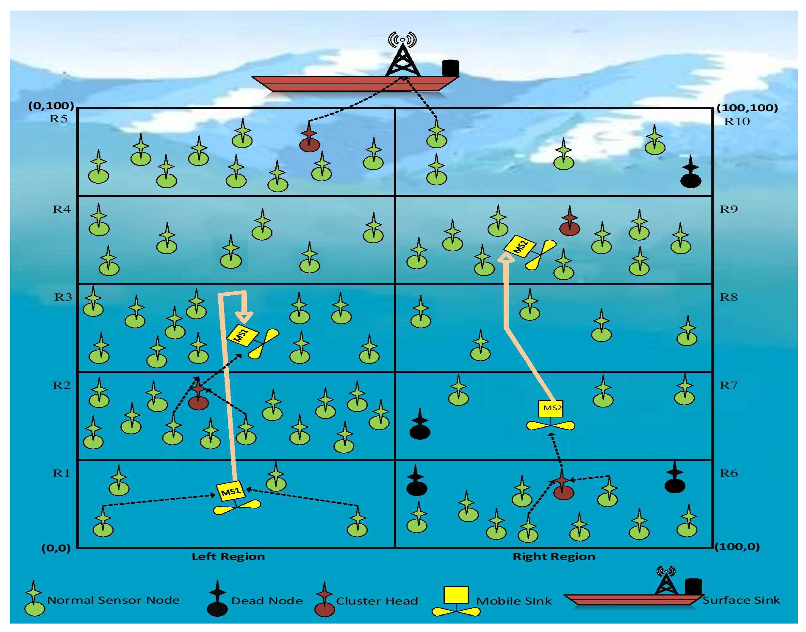
As discussed in [
11,
16], SEEC is a localization free protocol. In SEEC, the network field is divided into ten regions, each of which are subdivided into five left regions and five right regions. Two mobile sinks (MS1 and MS2) are used in sparse regions. MS1 changes its position from the topmost sparse region to the less sparse region in every round except the region of MS2. MS2 remains in the topmost sparse region until the death of all sensor nodes in that region. Both mobile sinks remain in the midpoint of the region. This movement of mobile sink in SEEC is not efficient because the deployment of nodes is random and the case may appear that the two of the most sparse regions are adjacent to each other either on the left side or on the right side. In this scenario, both mobile sinks will be in the same transmission range area. This movement leads to packet drop on the other side of sparse regions, which decrease the throughput of the network.
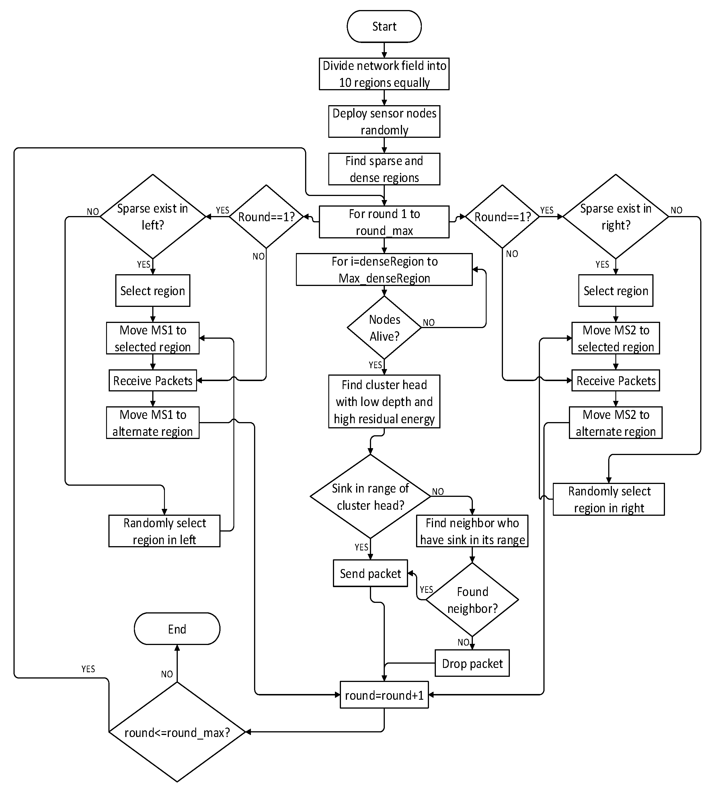
From the flow chart of SEEC [
11,
16], it is observed that the searching of sparse and dense region is done only once after the deployment of network. By the passage of time, due to ocean currents, sparse regions can be increased [
5]. Two mobile sinks are moved on the basis of sparse stack, which was not updated periodically. This factor also results in less throughput in SEEC [
11,
16].
The above discussion motivated to design a scheme that should utilize mobile sinks efficiently, which should result in better throughput and network lifetime.
5. Simulation Results
In this section, performance of the proposed scheme is compared with already existing depth based routing protocols of UWSNs: DBR, EEDBR and SEEC. Simulations are performed by creating a complete UWSN environment using MATALB [
28]. For simulation, 2200 rounds are run with the same parameters. All 100 of the sensor nodes are randomly deployed in the network field of 100 m × 100 m. The initial energy of each sensor node is 5 J [
11]. The transmission range of each sensor node is 50 m and depth threshold is 15 m. The sending and receiving power consumption of the sensor node is set to 2 W and
W, respectively [
7]. The size of the packet is 50 bytes [
7]. Simulation parameters are summarized in
Table 1.
To evaluate the performance of routing protocols, network lifetime, network residual energy, packets received per round, total packets received at sink, stability period and packet drop ratio are primary metrics. Besides these common metrics, we introduced a new metric: MUR. The definitions are given below:
Network lifetime is a total period (number of rounds) in which all the sensor nodes in the network die.
Network residual energy is defined as the total energy of each sensor node at specific intervals (rounds). It can be computed using Equation (
8):
where
is the calculated network residual energy,
is the residual energy of
sensor node and
is the total number of sensor nodes.
Total packets received at sink is also known as throughput. It is a summation of total packets received by all the sinks. It can be computed using Equation (
9):
where
is total number of packets received by all sinks,
is the total packets received by the
sink and
is the total number of sinks.
Stability period is defined as the round in which the first sensor node of the network die.
Packet drop ratio is a ratio of number of packets dropped by the sensor nodes to the total packets sent by the source nodes in any specific round (
r). The computation of the packet drop ratio in any specific round (
r) can be done using Equation (
10):
where
denotes the packets received in that specific round and
refers to the total packets sent in that specific round.
MUR is the new metric that is used to analyze the utilization of mobile sink in the routing protocol. Many routing protocols have been using mobile sink together with multi-hopping. This ratio tell us that how much of the total packets are gathered by the mobile sink. The equation to calculate MUR is defined as follows:
where
is the number of packets received by the mobile sink in any specific round and
refers to the total packets sent in that particular round.
5.1. Network Lifetime and Stability Period
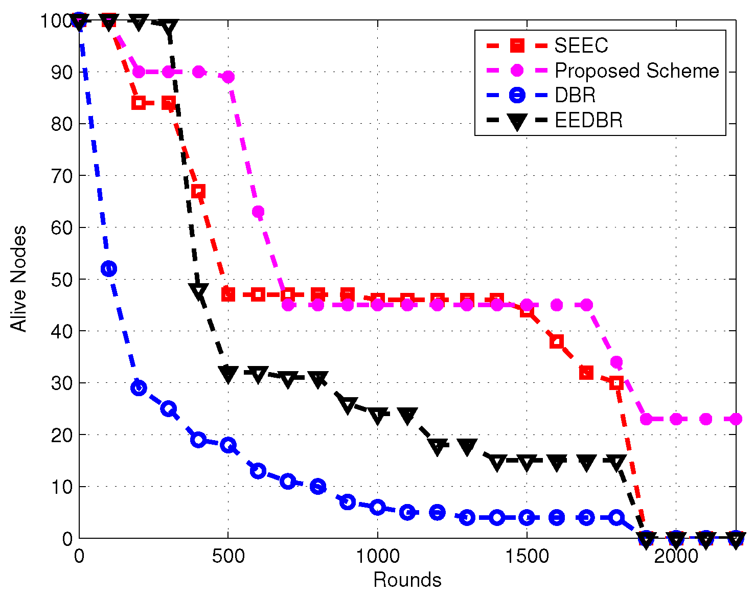
Network lifetime of the proposed routing protocol is improved as shown in
Figure 3. In SEEC, two mobile sinks have not been used efficiently. These sinks are moved in sparse regions only. This kind of movement can bring two sinks in adjacent regions e.g., Region 6 and Region 7. Considering the transmission range, it is not appropriate to use mobile sinks on the basis of sparse regions. In the proposed scheme, MS1 is restricted in the left region and MS2 is restricted in the right region giving priority to sparse regions. Moreover, clustering is also kept in dense regions. Both mobile sinks are moved alternatively in each round. This movement of mobile sinks with clustering in dense regions increased the network lifetime of the proposed routing protocol.
Sensor nodes are deployed randomly in the network field. There may be a case where sparse regions are less in number at the time of network deployment; however, the number may increase due to the ocean movement. In SEEC, the searching of sparse and dense regions is done only once during initial stages. In the proposed scheme, in addition to searching of sparse regions, due to the the alternate movement of mobile sinks, the stability period is better than SEEC, EEDBR and DBR as shown in
Figure 3. Moreover, the restricted movement of mobile sinks on the left side and right side also enhances the stability period.
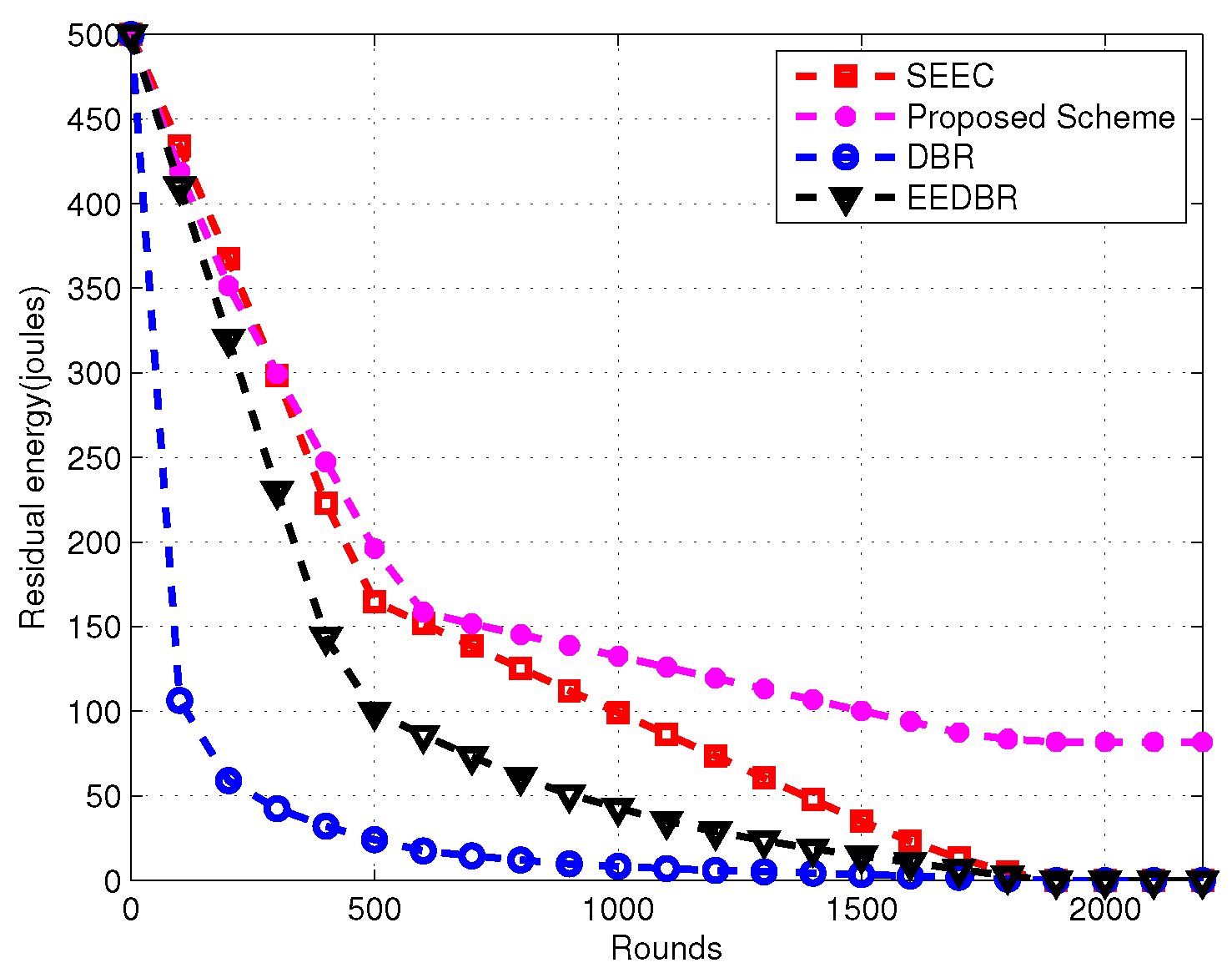
5.2. Network Residual Energy
In SEEC, two mobile sinks are used only in sparse regions while clustering is done in the top four dense regions. In EEDBR, the nodes with high residual energy and low depth are selected to forward data to sinks, which results in fast energy drainage of these nodes. In DBR, the selection criteria of the forwarder node are based on lowest depth only, which results in much energy consumption. In the proposed routing protocol, two sinks are restricted to left and right regions. Moreover, if the number of sparse regions are very lesser than dense regions; the movement of mobile sinks enhances the energy consumption. In spare regions, the nodes are far from each other, while, in dense regions, nodes are closer to each other. Total network residual energy consumption of SEEC, EEDBR, DBR and the proposed scheme is shown in
Figure 4.
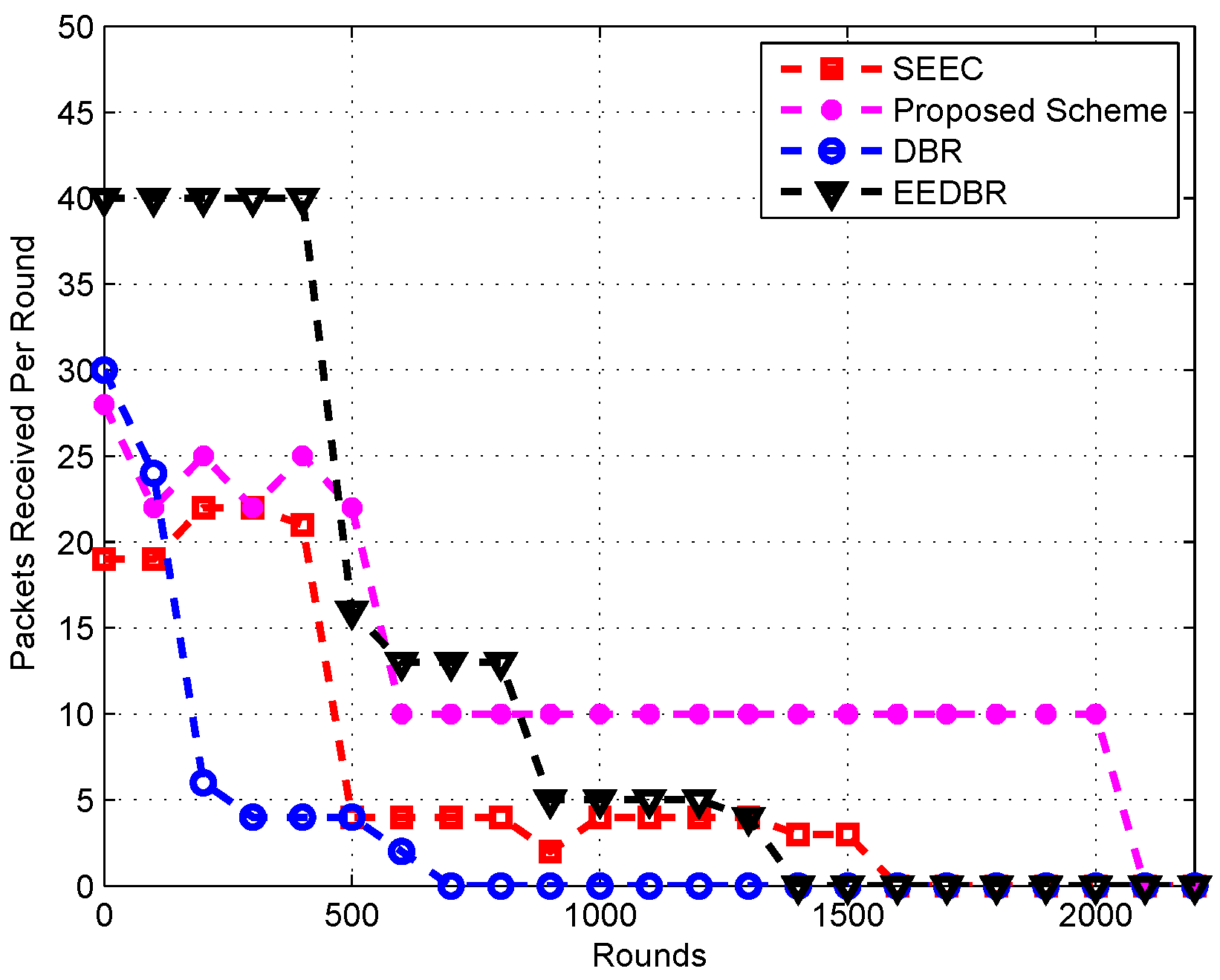
5.3. Packets Received Per Round
Figure 5 shows that, in the proposed scheme, the packets received per round at the sink are higher than all other routing protocols that are considered. This is due to the selection criteria of forwarding nodes. Packets received per round are also achieved in EEDBR at the cost of high residual energy. In SEEC, total packets received at the sink are smaller than that in the proposed routing protocol. This is because, in SEEC, the movement of mobile sinks is only based on sparse regions irrespective the adjacent sparse regions and transmission range of nodes. On the other hand, in the proposed scheme, mobile sinks are moved in alternative regions in every round. Consequently, the efficient movement of mobile sinks results in increased throughput.
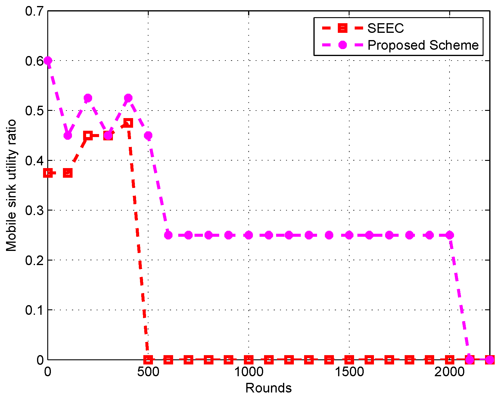
5.4. Mobile Sink Utility Ratio
It can be seen in
Figure 6 that the mobile sinks in the proposed scheme is used more for data packets collection compared to the SEEC. Please note that SEEC is the only protocol that uses mobile sinks amongst the compared protocols to our proposed scheme. Therefore, MUR and packet dropped ratio are compared only with SEEC to properly analyze the efficiency of mobile sink usage. The motion pattern of the mobile sinks in the proposed scheme results in the high MUR. In SEEC, the mobile sinks are used in the sparse regions only. The sparse region array is not updated periodically and, hence, this is the reason that, after 500 rounds, MUR becomes zero. The high MUR in the proposed scheme is also the reason for high throughput and less packet drop ratio. As discussed in
Section 3, for SEEC, the case may appear when both mobile sinks come in adjacent sparse regions of either the left or right side. In this scenario, the sensor nodes of the sparse region on the other side starts dropping the received packets. Thus, the total packets collected by the mobile sinks in SEEC remain lower, which is the reason for less MUR in SEEC.
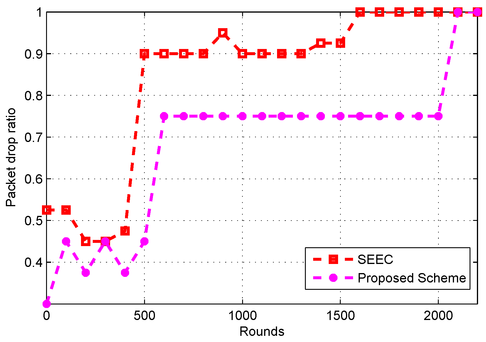
5.5. Packet Drop Ratio
Figure 7 shows that the packet drop ratio in the proposed scheme is less when compared to the SEEC. In the proposed scheme, mobile sinks are utilized efficiently, which results in less packet drop ratio. As discussed in
Section 3 that the SEEC categorizes the dense and sparse region at the initial stage and the mobile sink is moved on the basis of a sparse region searched array. This strategy of SEEC makes the movement of mobile sinks inefficient because, due to the water currents, it is not necessary that the sparse regions remain the same as they were in the initial stage. The movement of the mobile sink in constant searched array results in a high packet drop ratio. On the other hand, the restricted movement of mobile sink in the proposed scheme results in less packet drop ratio.
6. Conclusions
Results in this paper illustrate that the efficient and optimum utilization of mobile sinks play a crucial role in improving throughput and network lifetime of the routing protocol. Moreover, monitoring the utilization of the resources that are used in the protocol helps in improving the results of any routing scheme. In the proposed scheme, MUR is calculated in each round, which indicates the utilization of mobile sinks. The mobility pattern of the mobile sinks kept the MUR higher and thus the proposed scheme results in better throughput with balanced energy utilization.
The use of mobile sinks can result in high end-to-end delays. Consequently, delay in each round for the proposed scheme should be evaluated in future works. Additionally, a rigorous evaluation of MUR in various UWSN scenarios will be performed in the future. Additionally, evaluation of the proposed scheme in the 3D plane can be further investigated in the future. Moreover, the holding time mechanism can be applied to decrease the packet drop ratio.


 ,
, 


