1. Introduction
Three-level neutral-point clamped (NPC) inverters have been widely used in medium-voltage power conversion systems. Three-level NPC inverters have several advantages over conventional two-level inverters, such as reduced stress of the power device and enhanced output quality [
1,
2].
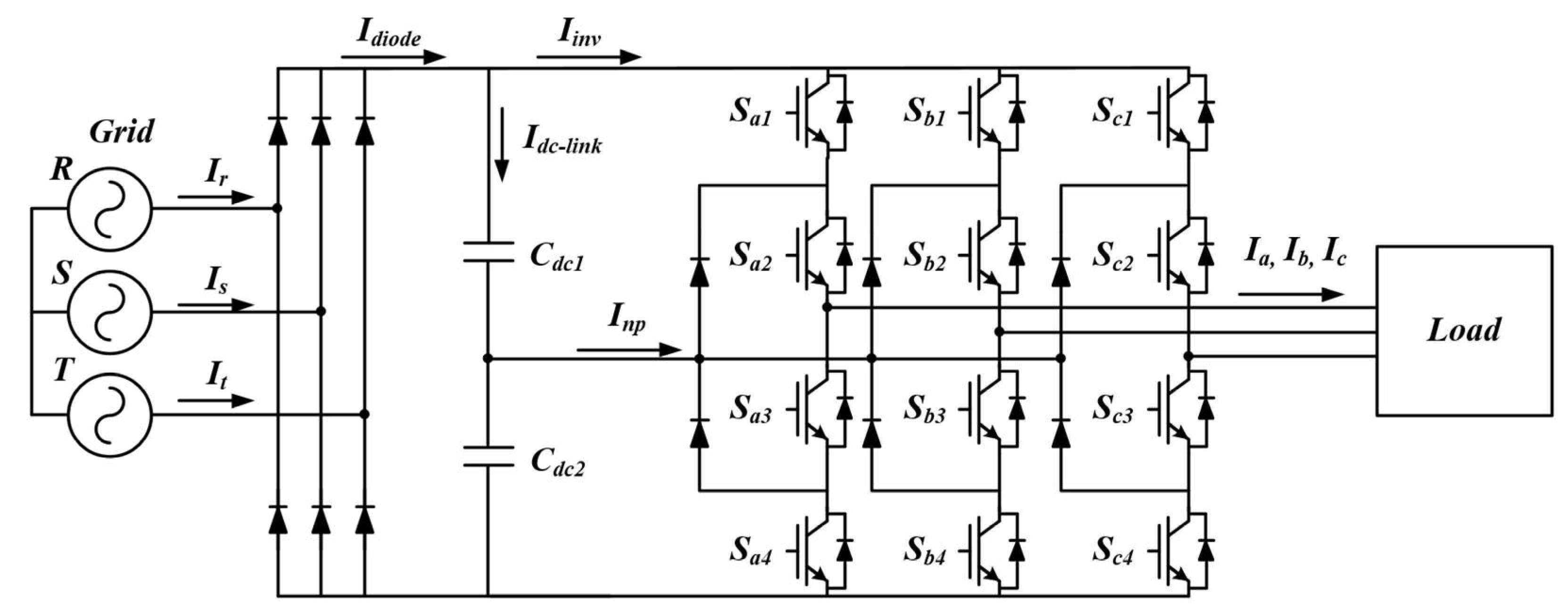
The conventional rectifier system for an inverter is shown in
Figure 1. Diode rectifier systems generally utilize capacitors with large capacitances to stabilize the operation of the inverter system. The purpose of the DC-link capacitor is to perform DC-link voltage regulation and to absorb the switching ripple current. Therefore, the DC-link of an NPC inverter is mainly composed of an electrolytic capacitor with a large capacitance. Moreover, the electrolytic capacitor occupies a lot of the space in the whole system. Furthermore, as electrolytic capacitors have a short life time. There is a decreased reliability of power-conversion systems [
3,
4,
5].
Therefore, many studies have focused on replacing electrolytic capacitors with film capacitors to reduce the volume of the system. While film capacitors have a much higher reliability, they have a much less capacitance per unit than that of electrolytic capacitors. A small film capacitor improves the reliability of the system and eliminates the initial charging circuit, thus reducing the overall system volume and cost [
6,
7,
8,
9].
In addition, film capacitors can store less energy than electrolytic capacitors. Therefore, film capacitors are unable to compensate for the input–output power difference. Small-capacity inverter systems are beneficial in applications such as fans, pumps, and compressors, where the load variation is not significant [
10,
11,
12].
To improve the quality of the input current caused by small capacitors, many researchers have studied various control techniques, including the use of the pulse-power injection method, output-current compensation technique, and harmonic injection technique [
3,
4,
6,
7,
8,
9,
10,
11,
12,
13,
14,
15]. In the case of [
8], the output-current compensation method distorted the output current in order to improve the input current. In [
11], there is a disadvantage in realizing high efficiency, as there is a need for a microprocessor that operates at high speed.
By increasing the demand in terms of small current distortion, low dv/dt stress and high efficiency, the three-level inverter is widely applied in various applications. However, the previous studies for the small DC-link system fed by the diode rectifier is based on the two-level inverters and there are considerable issues when the three-level inverter is applied in the small DC-link system. As shown in
Figure 1, the DC-link of the NPC inverter is divided into two voltage sources to generate three different output voltage levels; i.e., −
Vdc/2, 0, and +
Vdc/2. However, for the DC-link capacitors used in the three-level inverter, there is a difference between
Vdc1 and
Vdc2 owing to differences in manufacturing tolerances, mismatches in the switch characteristics, and the grid unbalance. The unbalance of the DC-link voltage includes alternating current (AC) unbalance and DC unbalance. The occurrence of a DC unbalance implies that two DC-link capacitors have different voltages, and the voltage difference does not change with time. The DC unbalance can cause the distortion of the output currents. The solution for the DC unbalance problem is to choose an appropriate switching-modulation method. The AC unbalance is an AC-ripple of
Vdc1 and
Vdc2, which change with time. The frequency of the AC ripple is three times the output fundamental frequency and the DC-link capacitor value. A large AC unbalance causes the output currents to contain the ripple frequency, which causes the distortion. Furthermore, a large AC unbalance imposes stress on converter devices. These problems from the AC unbalance become severe when the small capacitors are applied for the DC-link. In order to restrict the neutral-point AC ripple voltage, a neutral-point voltage stabilization method using DPWM and the offset injection method are used [
5,
16,
17,
18,
19,
20,
21,
22,
23,
24].
This paper focuses on the design and its control algorithm to improve the quality of the input–output currents generated by the three-level NPC inverter based small DC-link system. An applied DC-link shunt compensator (DSC) circuit solves the input current deterioration caused by the small DC-link capacitor. In addition, the output current quality is improved using the AC ripple-reduction algorithm. Finally, the performance and feasibility of the proposed method are verified using simulation and experimental results.
2. Description of Grid Current Improvement Technique
Generally, the DC-link capacitor in a three-level inverter compensates the power difference between the diode output power and the inverter input power through the charge-discharge operation of the capacitor. However, it is difficult to compensate for the instantaneous difference power owing to the decrease in the capacitance of the DC-link capacitor. In this section, the design method for the three-level inverter with the small DC-link capacitors is presented to shaping the rectified grid current [
10]. The rectified input current,
Idiode can be expressed as the sum of the inverter current that is consumed by the load and the charging current for the DC-link capacitor voltage, as shown in
Figure 1.
Assuming that the DC-link capacitance is very small, the DC-link current may be negligible. In this case, the quality of
Idiode is decided according to the inverter current,
Iinv.
Therefore, in order to improve the quality of the rectified input current
Idiode, it is necessary to change the inverter current
Iinv or add a compensation value to change the input current
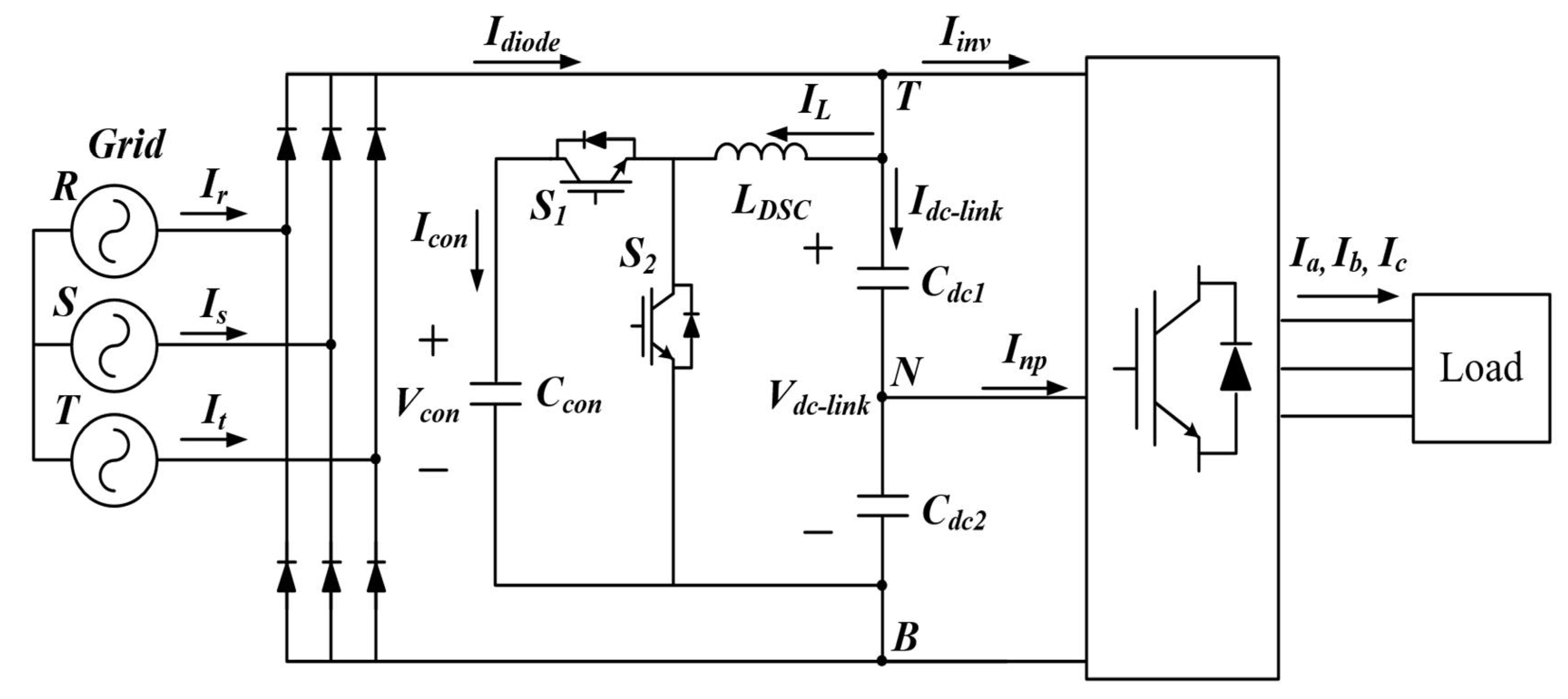
Idiode. The three-level inverter with an additional circuit is shown in
Figure 2. The additional circuit is called a DSC, which is used to improve the input current quality.
The proposed three-level NPC inverter consists of the small film capacitors that replace the large electrolytic capacitors and a DC-DC buck-boost converter. The inverter applying the large capacitors for the DC-link, the Idiode, flows for the period to charge the capacitors, and the period is relatively short because the capacitors have a large capacity. In case small capacitors are applied, most of the electric charge from the input grid is delivered to the load directly. Therefore, the Idiode flows consistently and its shape contains the six-order harmonic ideally because the three-phase grid currents are rectified by the diode rectifier. The proposed design method equips the DSC circuit to shape the Idiode into the six-order sinusoidal waveforms.
Assuming that the inverter uses small capacitors,
Idiode can be expressed as follows:
The inverter current
Iinv can be derived as:
where
Pinv is the inverter power,
Vdc0 is the average value of
Vdc-link, and
V6th is the 6th-order harmonic of the DC-link voltage. By substituting (4) into (3), the rectified input current is given as:
Assuming that there is a constant-power load in the inverter, the first term of (5) will have a DC value. However, because the second term is the 6th-order harmonic component of the DC-link voltage, it causes the degradation of the input current quality. Therefore, the compensation value is added to the current
IL, which flows in the DSC circuit, to improve the input current quality. The
IL with the added compensation value
Icomp is as follows:
where
Icon is capacitor current of
Ccon and
α is a weighting factor that adjusts the injected value of the compensative current. Finally, the input current Equation is given in (7). The input current can be improved by controlling the DSC circuit.
As recognizable by (7), if
α is 1,
Idiode is constant value (
Pinv/
Vdc0 +
Icon) and the input grid currents form square waveforms. By increasing the value of
α, the shape of
Idiode contains the six-order harmonic that become similar with
Idiode when the large DC-link capacitors are applied [
10,
25]. Therefore, the input grid currents also acquire the shape of sinusoidal waveforms by adjusting
α.
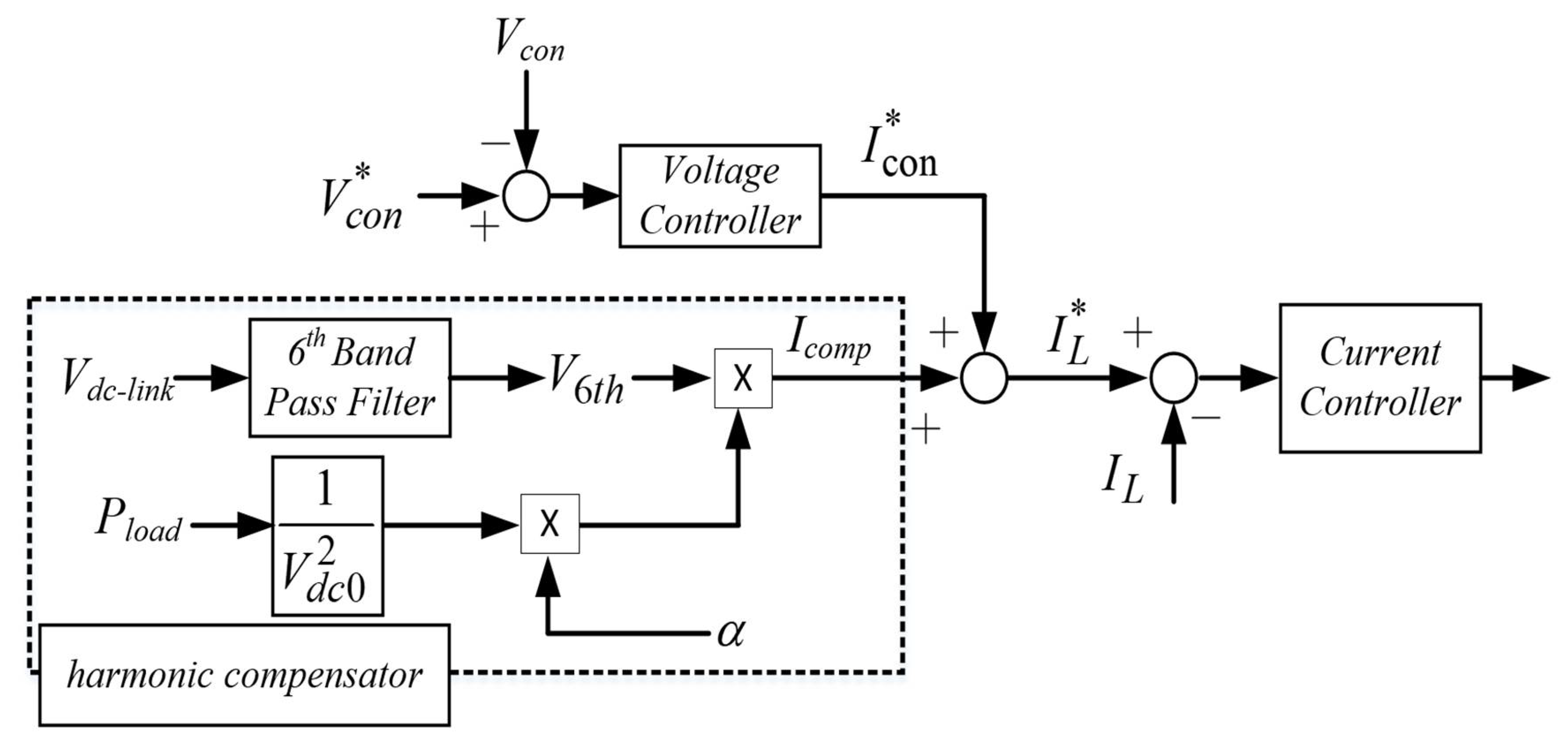
The control block diagram of the DSC is as shown in
Figure 3. The DSC controller consists of a voltage controller, harmonics compensator, and current controller. The voltage controller controls
Vcon, which is the output voltage of DSC. The harmonic compensator extracts the 6th-order harmonic of the DC-link voltage using the band-pass filter (BPF), and the 6th-order harmonic is used to calculate the compensative current
Icomp. The current controller controls
IL, which flows through the DSC inductor
LDSC. To compensate for the 6th-order harmonic,
Icomp is added to the reference signal
IL*.
Icomp consists of the product of the weighting factor alpha and
V6th, which is filtered by BPF. The bandwidth of BPF extracts the 6th-order harmonic of the DC-link voltage,
Vdc-link(
Vdc1 +
Vdc2).
3. AC Ripple-Reduction Algorithm for the Output Current
The quality of the input current can be improved by applying the DSC. However, because the DSC only improves the input current, a separate control technique is needed to improve the output current quality. For three-level NPC inverters, there is an AC ripple in the DC-link. The charge-discharge of the capacitor voltage is determined according to the switching state and the direction of the neutral-point current, Inp, which flows through the neutral-point, N. In addition, the values of Vdc1 and Vdc2 are not the same and fluctuated. Therefore, the three-level inverter also generates the distorted pole voltages under the large AC ripple condition of the capacitor voltages. The distorted output pole voltage degrades the quality of the output current. Hence, Vdc1 and Vdc2 should be controlled with the same value to realize the improved output current quality.
The three-phase voltage references are expressed as:
where
vm is the magnitude of the phase voltage.
The reconfigured on-time ratio of the three-level NPC inverter is as follows:
where
rx,ref is within the range of
. For every switching cycle, the on-time ratios can be classified as
rmax,
rmid, and
rmin, which represent the maximum, middle, and minimum values of the three-phase on-time ratios, respectively.
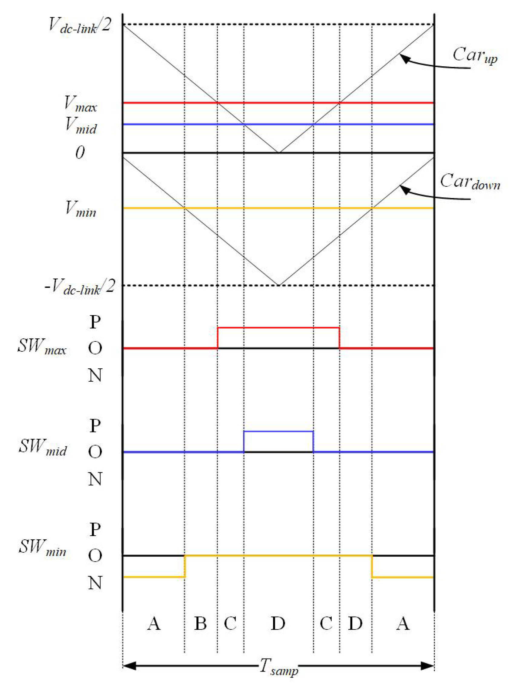
For the carrier-based PWM (CB-PWM), the switching state is as shown in
Figure 4. During the control period, the switching state changes six times. In sector A, the min-phase is in the N state; therefore, all of the switching states become [OON]. In sector B, the min-phase changed to the O state and all of the switching states become [OOO]. In sector C, the max-phase changed to the P state and the switching state becomes [POO]. Similarly, in sector D, the max-phase and min-phase hold the switching state, and the state of the mid-phase changes to the P state. Therefore, the switching state is changed [PPO]. During the control period, the switching state changes as follows: A→B→C→D→C→B→A. The variation of neutral-point voltage according to the switching state is given in
Table 1.
The neutral-point voltage (
Vdc2 −
Vdc1) varies depending on the switching state and the direction of the neutral-point current
Inp.
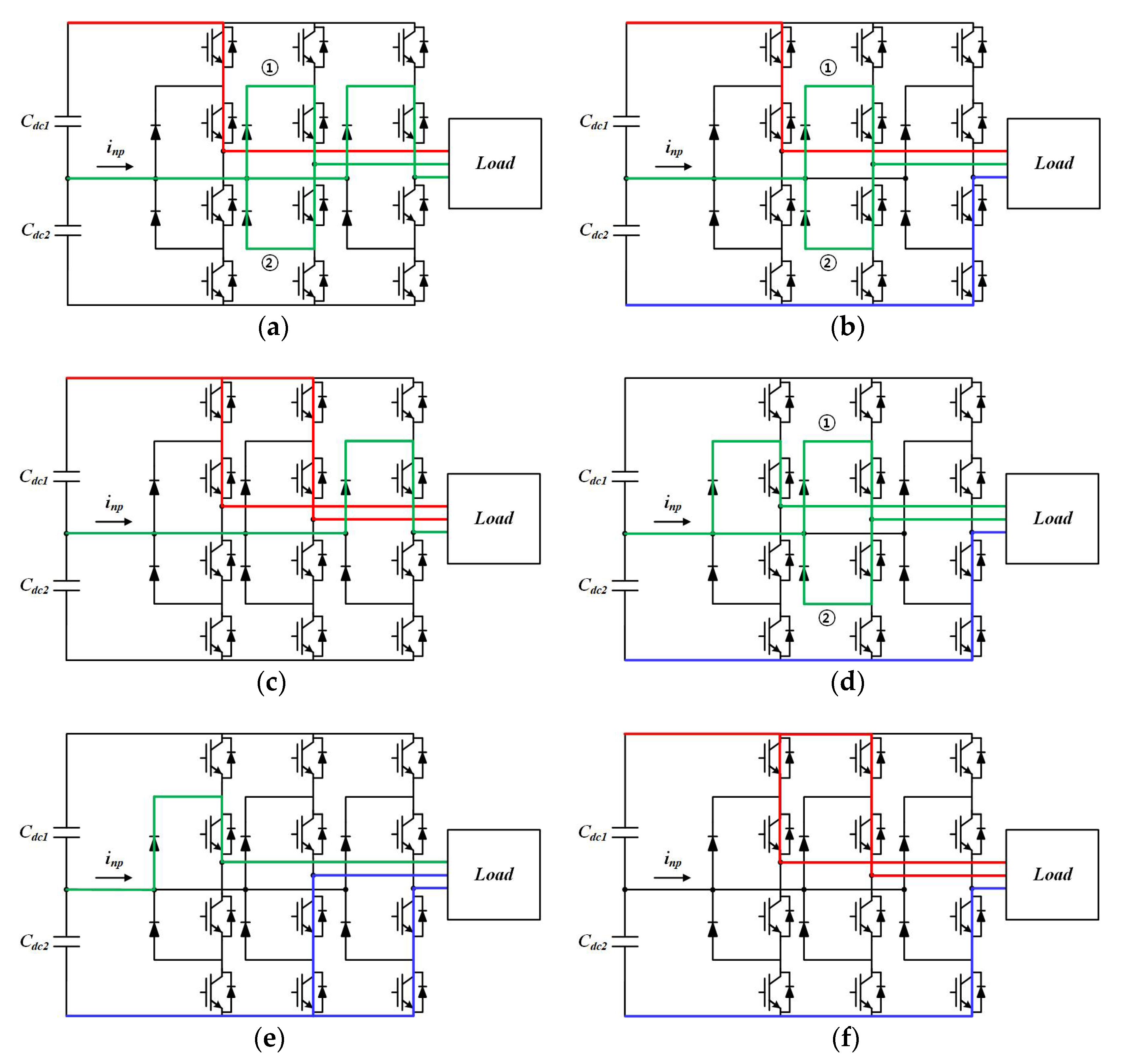
Figure 5a shows the [POO] switching state. The max-phase switch is the P clamping state. In this case, the neutral-point is connected to mid- and min-phases. Therefore, the neutral-point current equals −
Imax. In addition, the upper capacitor,
Cdc1 is discharged. As a result, the neutral-point voltage will decrease.
Figure 5b shows the [PON] switching state. The max-phase switch is in the P clamping state and the min-phase switch is in the N clamping state. In this case, the neutral-point is connected to the mid-phase. Therefore, the neutral-point current is equal to
Imid. However, because the current in the mid-phase has either a positive or a negative value, the direction of the current has two cases. Assuming that
Imid is larger than zero, the neutral-point current flows to current path ① in
Figure 5b and the voltage of the lower capacitor is discharged. Therefore, the neutral-point voltage increases.
Figure 5c shows the [PPO] switching state. In this case, the neutral-point is connected to the min-phase. Therefore, the neutral-point current is equal to
Imin. Then, the
Vdc2 voltage increases, resulting in an increased neutral-point voltage. For the [OON] switching state, the neutral-point is connected to the max-phase and mid-phase. The neutral-point current is equal to
−Imin.
Imin, which is always a negative value. Therefore, in the [OON] state, the neutral-point voltage decreases because the neutral-point current is a negative value. Similarly, for the [ONN] switching state, the neutral-point is connected to the max-phase, and the neutral-point current is equal to
Imax, as shown in
Figure 5e. Because the value of
Imax is always positive, the neutral-point voltage decreases. Finally, the [PPN] and [PNN] states are disconnected from the neutral-point. Therefore, the neutral-point voltage is constant.
It can therefore be confirmed that the variation of the neutral-point voltage fluctuates with the neutral-point current [
26]. The
vmax phase is always connected to point T, at during the product
rmax and the
Tsamp. The
vmin phase is always connected to point B, during the product |
rmin| and
Tsamp. However, the pole of a phase with the middle value is connected to T or B when
rmid is positive or negative during the product |
rmid| and
Tsamp. In addition, assuming that the three-phase output current, DC-link voltage, and the reference signal do not change during one control period, the current at the neutral-point, which is expressed in [
27], can be given as:
where
Imax,
Imid, and
Imin are output currents that flow during each turn-on period of
rmax,
rmid, and
rmin, respectively.
<x>Ts represents the average value during one control period.
In the switching waveforms shown in
Figure 4, additional switching should be injected to minimize the neutral-point voltage for the ripple minimization in the neutral-point voltage. Therefore, the offset is added to the reference signal to minimize
Inp. The mean value of
Inp, which is added to the reference signal by the offset, is as follows:
In (12), rmax is always positive and rmin is always negative. However, rmid and roff can have either a positive or negative value. In addition, roff should be lower than rmax and higher than rmin.
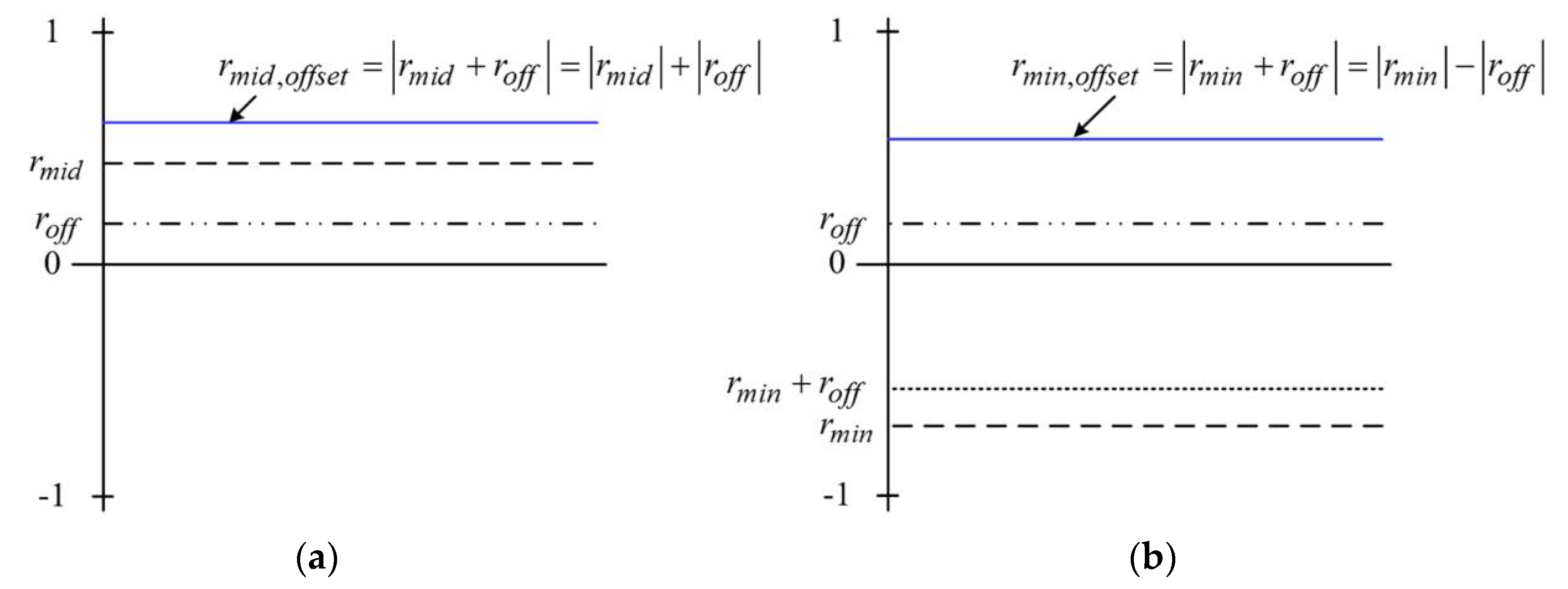
Case 1 (
rmid > 0 and
roff > 0): Assuming that
rmid > 0, as shown in
Figure 6,
rmin,offset, which is added to
roff, is subtracted from the absolute value of
rmin to the absolute value of
roff. Then, using (11), the neutral-point current is added to the compensation value as follows:
From (13),
roff, which causes
<Inp>Ts* to be zero, is derived as follows:
Because the denominator should have a positive value,
roff can be expressed as:
Case 2 (
rmid < 0 and
roff > 0): In this case,
<Imid∙|rmid+roff|>Ts has two cases, as shown in
Figure 7.
In case 2, the two values were compared to calculate two each value. First, in case 2-1, assuming that |
rmid| > |
roff|, the neutral-point current is as follows:
Similar to case 1, the value for making the neutral current equal to zero is derived as:
In the second case 2-2, assuming that |
rmid| < |
roff|, the neutral-point current can be estimated as:
The offset value required to make the neutral current equal zero is as follows:
In this case, the denominator term is over zero, and
roff > 0. Therefore,
roff can be expressed as:
Case 1 and case 2 were calculated when roff is positive. On the contrary, case 3 and case 4 calculate the offset value when roff is a negative value.
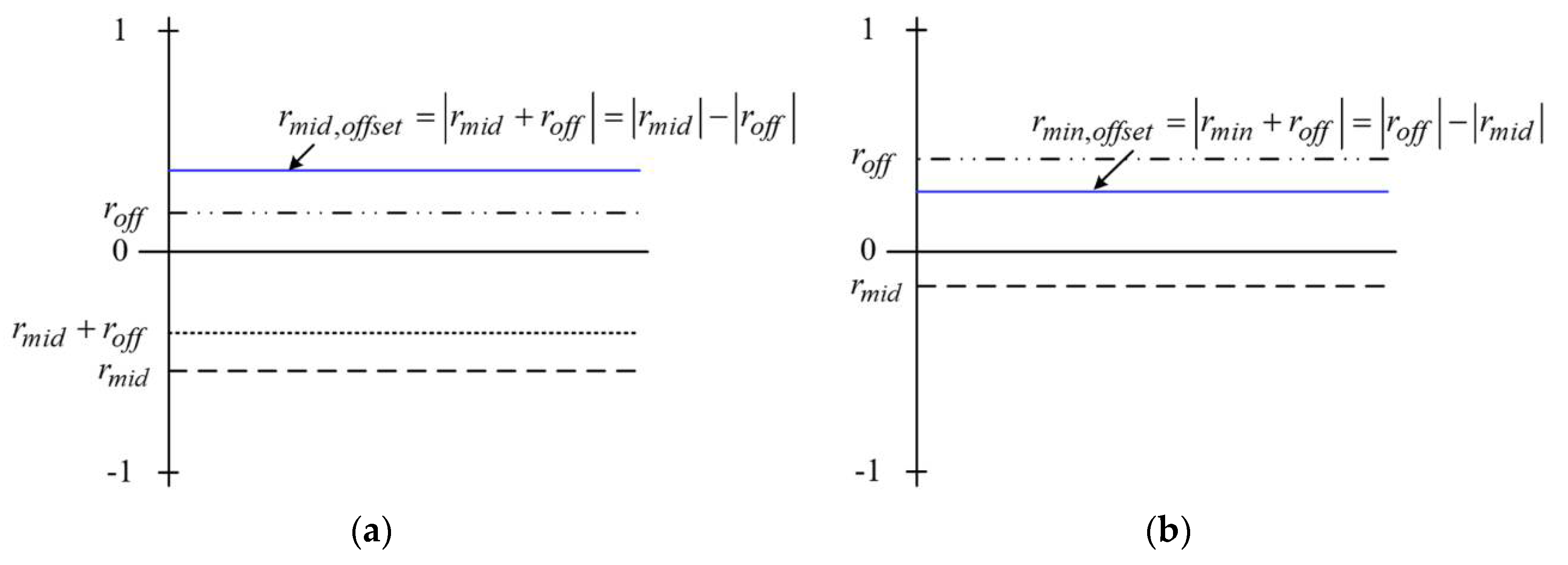
Case 3 (
rmid > 0 and
roff < 0): This case is similar to case 2 because the absolute value of
roff may be different from the absolute value of
rmid. Therefore, for case 3, there are two ways to calculate the offset value, which is shown in
Figure 8.
In case 3-1, assume that |
rmid| > |
roff|; then, the neutral-point current is derived as:
The offset value is used to compensate the neutral-point current equal to zero as:
In this case, because the denominator is less than zero,
Inp must be negative. By using the condition that
Inp and
roff are less than zero, the offset value can be expressed as:
For case 3-2, |
rmid| < |
roff|. Similar to case 2-2, the offset to make the neutral-point current equal to zero is given as:
Case 4 (
rmid < 0 and
roff < 0): In this case, the compensation value can be obtained similarly to case 1. Finally, the offset is used to make the neutral-point current equal to zero.
Based on the calculation for cases 1 to 4,
roff can be summarized as shown in
Table 2.
However, in all regions, the sum of
roff and
rx.ref should be maintained within the range
. Therefore, the range of each on-time ratio is determined as follows:
The final on-time ratio and the injected
roff can be derived as:
The reconfigured reference voltage obtained using the proposed method makes the average value of the neutral-point current for a switching period (<Inp>Ts) equal to zero, thus suppressing the ac ripple in the neutral-point of the DC-link.
4. Simulation Results
Simulations were performed to verify the effectiveness of the proposed method using the tool PSIM. The simulation circuit of the drive system is given in
Figure 2. The simulation parameters are indicated in
Table 3. The output fundamental frequency is 60 Hz and the output MI is 0.75.
Cdc-link is the series value of
Cdc1 and
Cdc2.
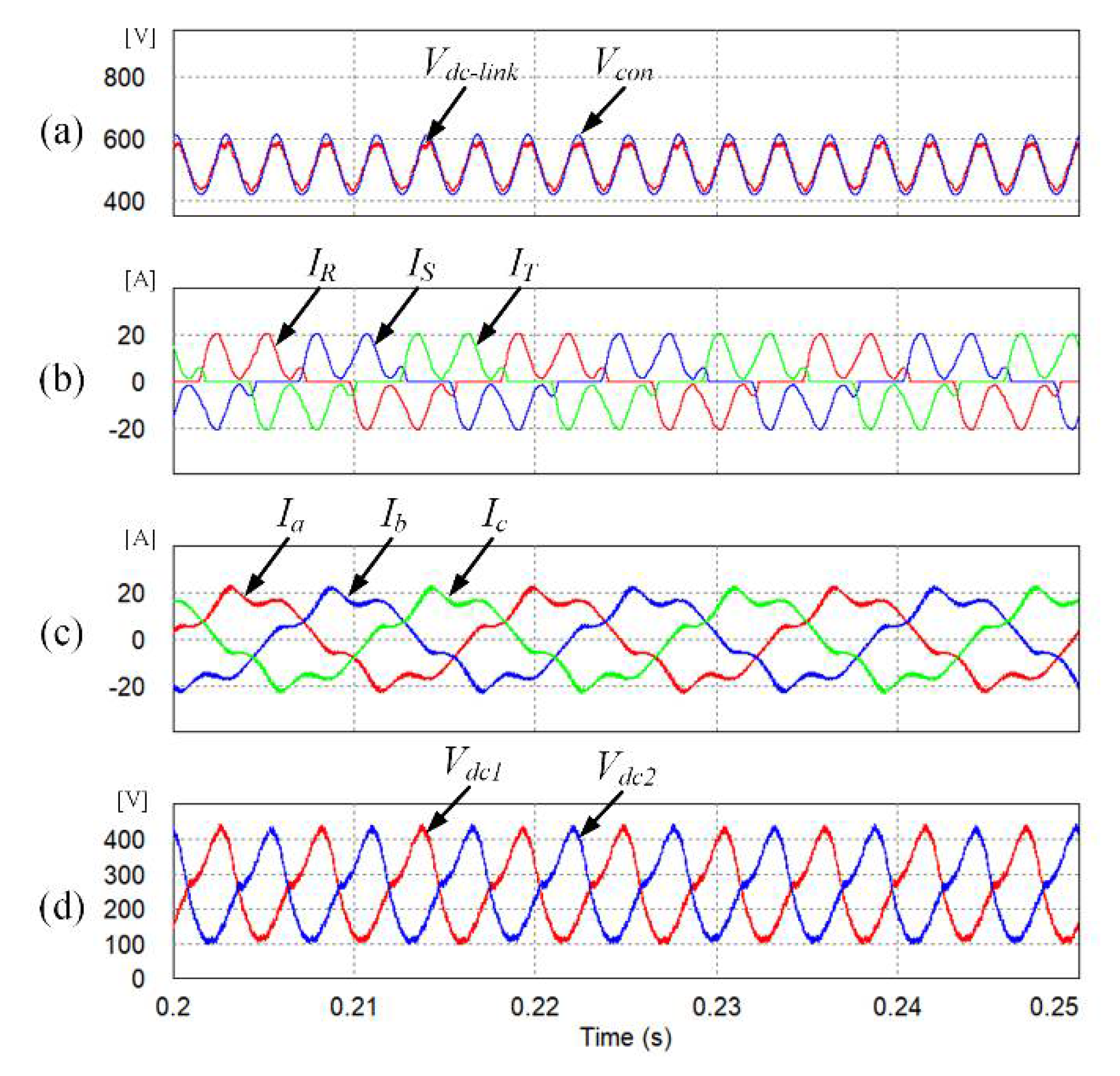
Figure 9 shows the simulation results of the three-level inverter without any proposed control scheme. The input current total harmonic distortion (THD) is 68.76%, which is not suitable for the limits of the THD specified by IEC 61000, which is the international standard for input current. In addition,
Figure 9d shows the DC-link voltage of the three-level inverter. The neutral-point voltage ripple is very large when the algorithm is not applied. As a result, the output current THD is 17.78%, as shown in
Figure 9c.
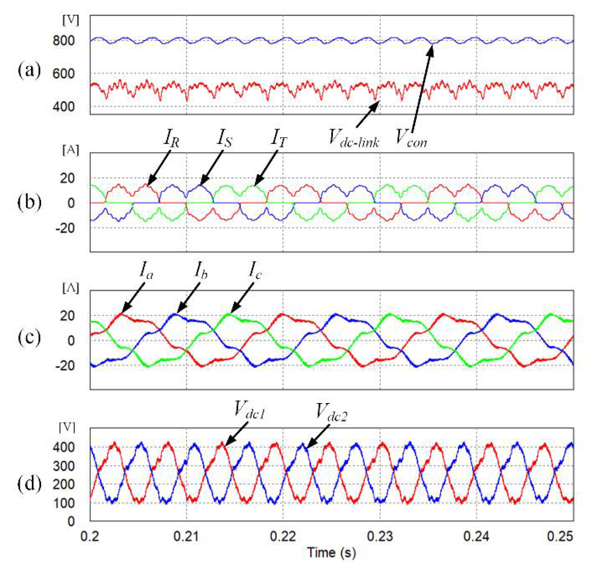
Figure 10a shows the DC-link voltage and the voltage
Vcon.
Vcon was set to 800 V using DSC control. Therefore, the quality of the input currents is improved and the THD becomes 37.57%. However, because the ripple of the neutral-point voltage was not reduced, the quality of the output currents was slightly improved. As a result, there is no improvement in the THD of the output currents, which is 14.44%.
However, because the ripple of the neutral-point voltage was not reduced, the quality of the output currents was slightly improved. As a result, there is no improvement in the THD of the output currents, which is 14.44%.
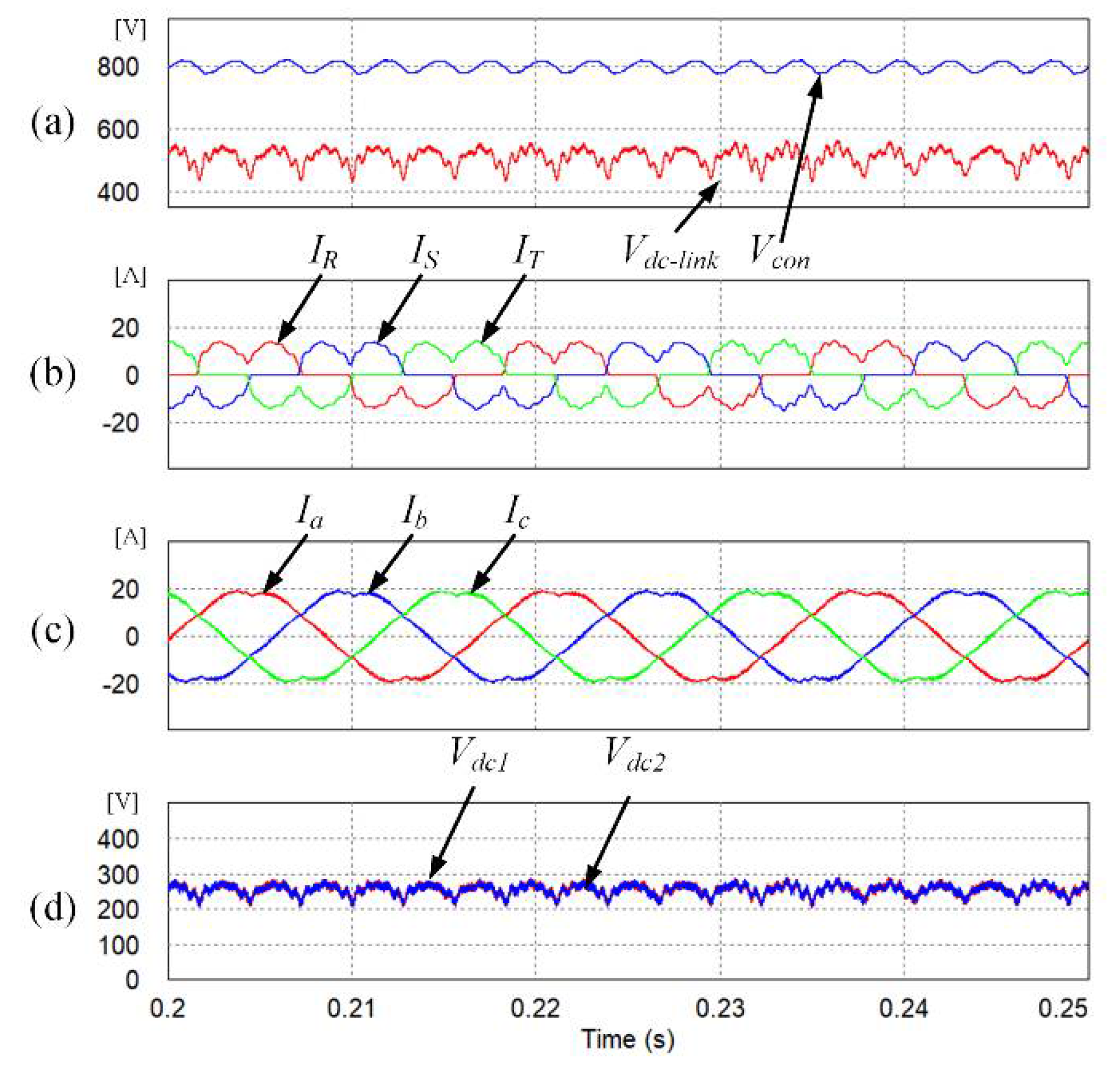
Figure 11 shows the simulation results obtained for the proposed algorithm, DSC, and the AC ripple-reduction. The DC-link voltage of the three-level inverter is shown in
Figure 11d. The AC ripple-reduction algorithm reduces the neutral-point voltage. Finally, the THD of the input current is 36.42% and the output current is 5.14%.
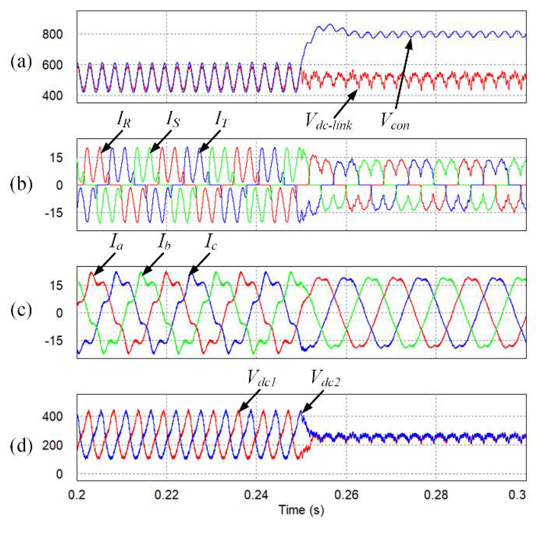
The simulation results of the transition operations are shown in
Figure 12. The proposed algorithm is applied at 0.25 s. As the control scheme changes, the input–output currents are well controlled. Owing to the control scheme change, the quality of the input–output currents is improved and the ac ripple of the neutral-point voltage is reduced.
Finally, the THD of the input currents is improved from 67.50% to 36.51% by using the DSC. Furthermore, the THD of the output currents is improved from to 16.44% to 4.46% by using the ac ripple-reduction algorithm.
5. Experimental Results
The experimental results are presented to verify the feasibility of the proposed design and control method in actual implementation.
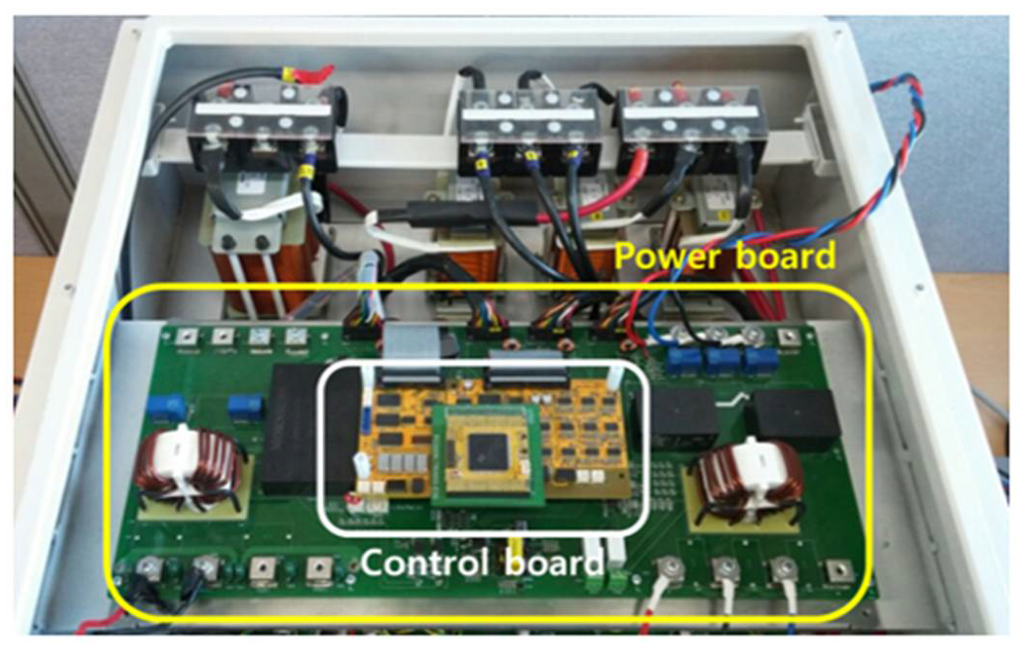
Figure 13 shows the hardware set-up including a control board, NPC inverter and three-phase diode rectifier. The control board consists of a digital signal processor (DSP) TMS320F2833 (Texas Instruments Co., Dallas, TX, USA) and other peripherals. The parameters of the experiment are the same as the simulation, as indicated in
Table 3.
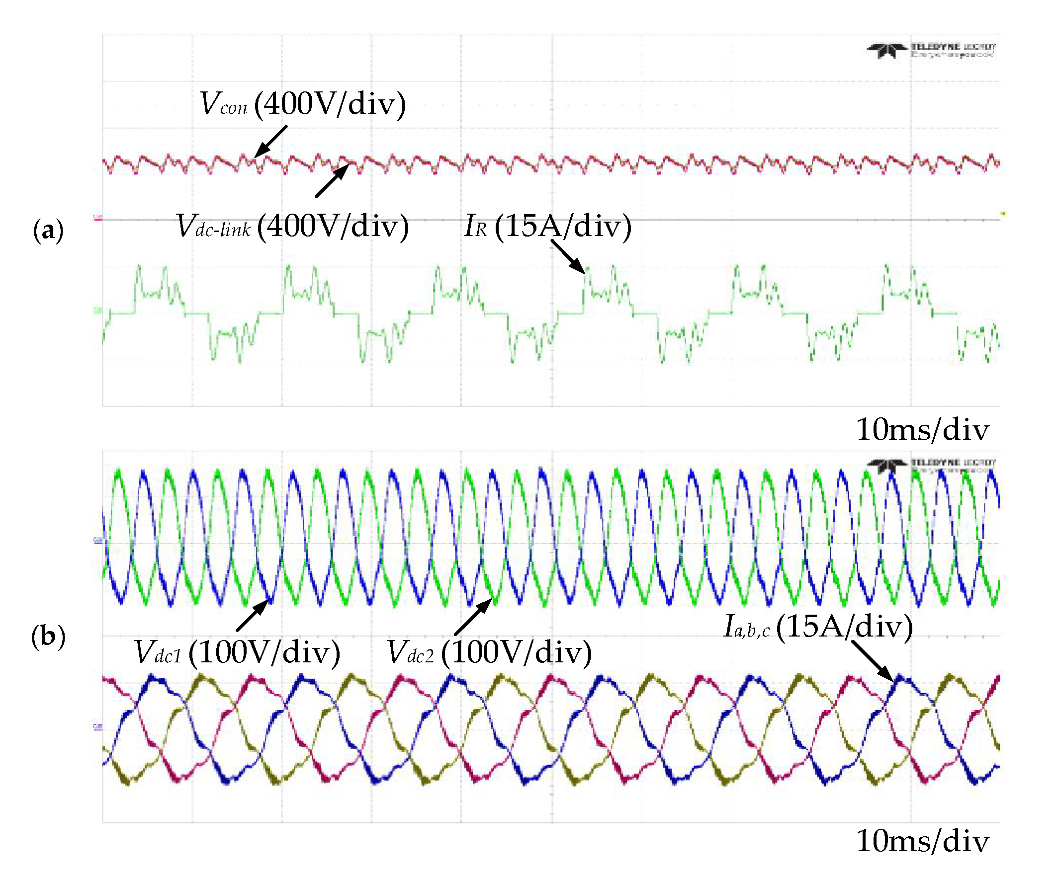
Figure 14 shows the experimental results obtained for the case using the conventional sinusoidal pulse-width modulation (SPWM). The DC-link voltage fluctuates at 538 V owing to the presence of the diode rectifier. Because the DSC controls are not performed,
Vcon has the same magnitude as
Vdc-link. Therefore, the input current quality is very low and the THD is 59.07%.
Figure 14b shows the capacitor voltage in the DC-link and the output current. In the three-level NPC inverter, the output pole voltage is not constant because of the fluctuating neutral-point voltage, so the output current is distorted.
Vdc1 and
Vdc2 have voltage ripples of about 250 V, and the THD of the output current is 13.2%.
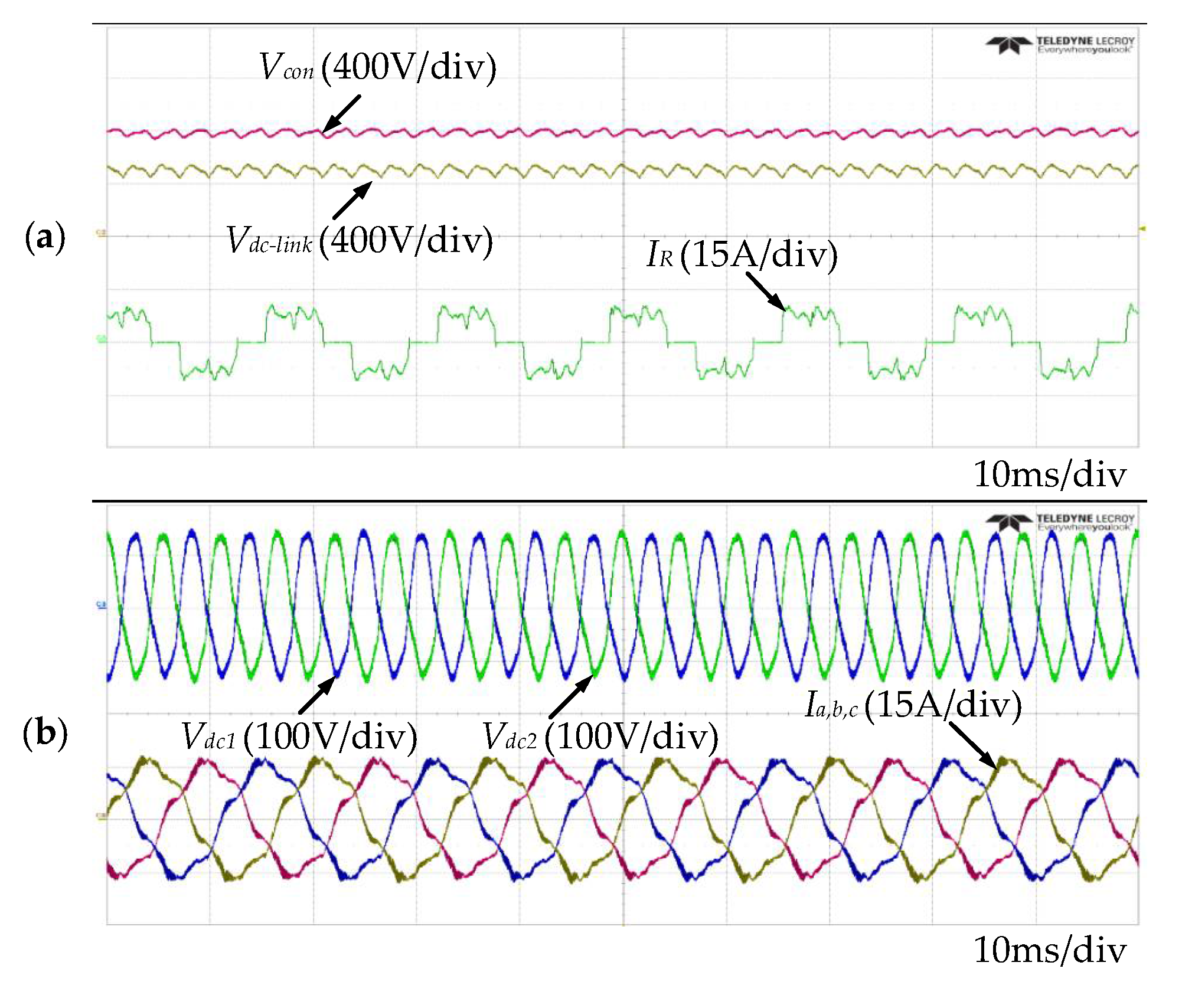
Figure 15 shows the experimental waveforms for the DSC control.
Figure 15a shows the DC-link voltage and the input current. Because the DSC in not applied, the THD of the input current is equal to 53.18%.
Figure 15b shows the waveform after the ac ripple-reduction algorithm is applied.
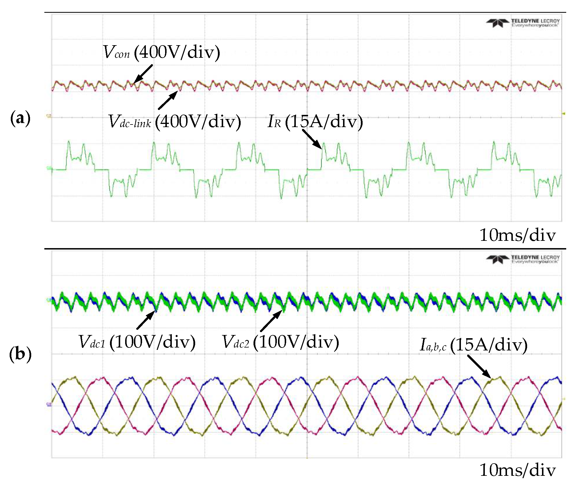
Figure 16 shows the experimental waveforms obtained when only the ac ripple-reduction control is applied.
Figure 16a shows the DC-link voltage and the input current. The DC-link voltage fluctuates at 538 V because of the diode rectifier, as shown in
Figure 14a.
Vcon was set to 800 V. DSC control improves the quality of the input currents, and the THD is improved to 35.68%. Moreover, the magnitude of the AC ripple in the neutral-point voltage was reduced to 50 V. As a result, the output pole voltage becomes more constant and the quality of the output currents is improved. In this case, the THD of the output currents is decreased to 2.13%.
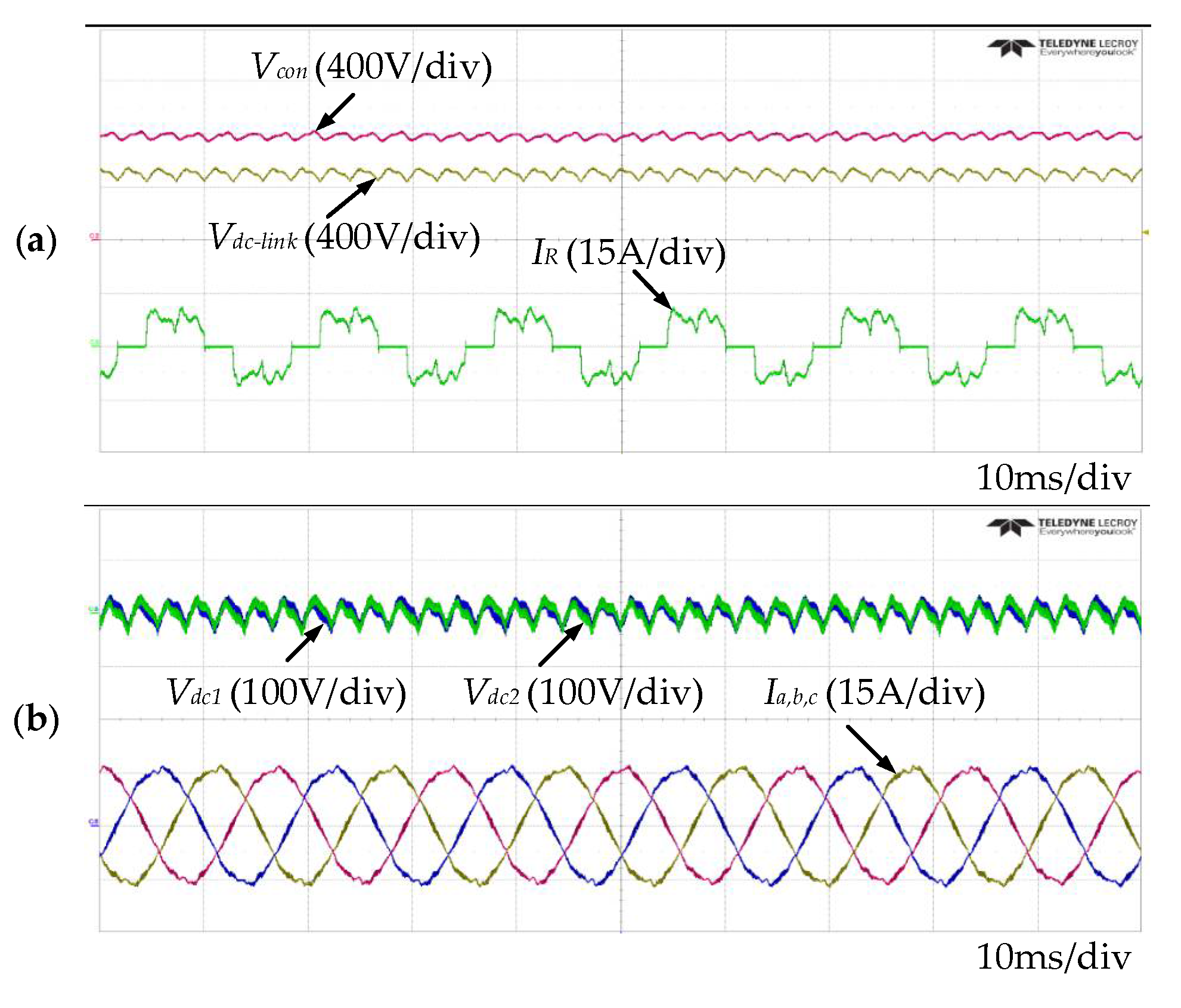
Figure 17 shows the output waveform of the proposed algorithm. The DSC circuit improves the quality of the input current. In addition, the ac ripple-reduction of the neutral-point voltage algorithm improves the quality of the output current. As shown in
Figure 17a, the voltage of
Vcon was maintained at 800 V. In this case, the THD of the input current is 35.78%.
Figure 17b shows the voltages
Vdc1 and
Vdc2 after applying the ac ripple-reduction algorithm, and the distortion of the output current was reduced. The output current THD is equal to 1.75%.
