Article

A Fuzzy Logical-Based Variable Step Size P&O MPPT Algorithm for Photovoltaic System

College of Engineering, Swansea University, Bay Campus, Swansea SA1 8EN, UK
*
Author to whom correspondence should be addressed.
Energies 2018, 11(6), 1340; https://doi.org/10.3390/en11061340
Submission received: 28 March 2018 / Revised: 19 May 2018 / Accepted: 22 May 2018 / Published: 25 May 2018

Abstract

:
This paper presents a Modified Perturb & Observe (P&O) Maximum power point tracking (MPPT) algorithm using fuzzy logic-based variable step size to overcome some of the limitations associated with the conventional P&O MPPT tracking method to improve the transient response and reduce the steady-state terminal voltage oscillations. The proposed MPPT algorithm was implemented and tested on an indoor emulated PV source that is constructed from a conventional solar panel and a DC power supply, a boost DC-DC converter and a dSPACE-based MPPT controller. The advantage of implementing this testing platform for MPPT is easy implementation and indoor testing of MPPT algorithms and DC-DC power converters. Thus, dependency on atmospheric conditions such as irradiance level can be avoided. Details of the emulated PV source mathematical model and electrical characteristics, the proposed MPPT algorithm via dSPACE, simulation and test results were presented in the paper.

1. Introduction

Renewable energy is increasingly becoming popular due to environmental degradation caused by widespread use of fossil fuel. The extensive use of fossil fuel results in potential economic upheaval, massive pollution issues as well as greenhouse gases which leads to climate change. All these environmental degradations have increased the demand for green energy produced by renewable energy sources, such as solar energy, geothermal energy, tidal energy, biomass, biofuel and hydroelectric energy [1,2].
In recent years, there has been more research emphasis into Photovoltaic (PV) solar energy which is growing at an unprecedented rate as this is one of the newest and cost-effective ways to meet the enormous energy needs of humanity in the 21st century [3].
Power electronics PV inverters are core components of any PV system, which convert the variable direct current (DC) output of the PV array into a utility frequency alternating current (AC) that can be fed into the electrical grid. PV converters are essential in an operating PV system to maintain the power output at the maximum power point; this control function is achieved by employing MPPT algorithms. Also, significant research effort has also enabled development of a range of PV inverters with the aim of maximising the efficiency of solar energy conversion systems [4,5,6].
This paper proposed a modified perturb and observe (MP&O) MPPT algorithm using fuzzy logic-based variable step size to overcome some of the limitations associated with the conventional P&O MPPT tracking method discussed in [7,8]. These limitations are slow convergence or rising time towards maximum power point (MPP), oscillation of PV power in steady state conditions around (MPP) resulting to power loss and abrupt change of MPP position under variable atmospheric conditions. The proposed MP&O MPPT technique was simulated and validated via a PV emulator and dSPACE-based rapid control prototyping (RCP) system. The test system provides a PC-based simulation platform as well as allows for the fast implementation of control algorithms in a real-time environment developed within MATLAB® and Simulink® 2016a. The PV emulator mathematical model and electrical characteristics, as well as circuit connection, were also shown. Simulation and experimental results of the proposed MP&O MPPT algorithm show the method is efficient in tracking the maximum power point with changes in solar irradiance.

2. Maximum Power Point Tracking Techniques

Maximum power point tracking (MPPT) is a significant mechanism in a PV converter; it is used to ensure that the PV converter extracts the maximum power generated by the PV module. The electrical characteristics of a solar PV under changing solar irradiance are manifested in the output voltage and current. Effective control of the PV source terminal voltage maintains a value such that the product of PV voltage and current achieves a maximum value, known as the maximum power point (MPP). This point is at the “knee” of the PV diode normal I-V curve with limits of open circuit current (Voc) and short circuit current (Isc) as shown in Figure 1.
PV maximum output power varies due to weather conditions such as irradiance. Therefore, MPPT is required for PV converters to capture the maximum possible power from the connected PV module by regulating its voltage or current. Various MPPT algorithms have been discussed in [9,10,11,12,13,14,15], among these, the most often applied MPPT techniques are Perturb and Observe (P&O)-based MPPT approaches. Despite P&O been widely used in tracking MPP, this method is applied mainly in tacking single maximum power point as they fail to track global maximum power point (GMPP) when PV panels are affected by partial shading which lead to multiple local maximum power point (LMMP). However, to resolve this limitation the scanning of the PV panel characteristics in a nonlinear manner by using generic algorithm (GA) with P&O embedded into the structure of the GA to create a single algorithm which can track multiple LMPP was proposed in [16]. In addition, global maximum power point tracking (GMPPT) control strategy combining the conventional perturb and observe (P&O) algorithm and the Fireworks Algorithm (FWA) was also proposed in [17] to resolve the limitations of multiple local maximum power point.
The principle of P&O MPPT techniques is to measure the derivative of PV array voltage ∆V and the derivative of PV array output power ∆P in order determine the movement of the PV array operating point. The technique operates by periodically perturbing (i.e., incrementing or decrementing) the PV array voltage. If an increase in PV operating voltage leads to increase in output power, the operating point of the PV array will be in the left of the maximum power point (MPP) hence further voltage perturbation is required towards the right to reach MPP as shown in Figure 1. However, if the increase in voltage leads to a decrease in power the operating point will be to the right of MPP of the PV array hence further perturbation is required to towards the left to reach MPP. In this process, the output power continuously oscillates around the MPP of the PV array due to the perturbation in PV output voltage.
Due to its simplicity and cost-effectiveness, P&O MPPT can easily be implemented in tracking maximum power point of a PV array. The disadvantages of this method are poor tracking possibly in under sudden changes in irradiance such as the slow convergence of rising time towards maximum power point. This method also results in continuous oscillations of PV output power around the MPP in steady-state conditions [18,19,20].
Various methods have also given an account on how to improve the dynamic behavior of conventional P&O MPPT techniques such as the method based on optimising the sampling interval rate according to the converters dynamics [7,21]. Furthermore, a variable step size-based method which automatically turned perturbation steps of the PV array operating points when there is a change in solar radiation was proposed in [22,23,24,25,26] to resolve the limitations characterised by the conventional P&O MPPT techniques.
Incremental conductance (IC) algorithm was also proposed to resolve the mentioned limitations associated with the conventional P&O algorithm by applying the PV array incremental conductance to compute the sign of ∆P/∆V without perturbation. This technique was created on the fact that the slope of the PV array power curve is zero at the maximum power point which is expressed by Equation (1).
d P P V d V P V | V M P P = = 0
The technique enforces a voltage on the PV module at every iteration, measures the incremental change in conductance ΔIpvVpv and compares it with the instantaneous conductance Ipv/Vpv to decide the operation for tracking maximum power point MPP. This algorithm has an advantage over P&O as it can calculate the direction in which to perturb the array operating point to reach MPP and stop perturbing when MPPT has reached its maximum operating point. Also, under rapidly changing atmospheric conditions it does not track in the wrong direction away from MPP [27,28]. However, the main drawback of incremental conductance MPPT algorithm is the complexity of its hardware implementation as its need to not only measure the current and voltage but as well calculates the instantaneous and incremental conductance value.

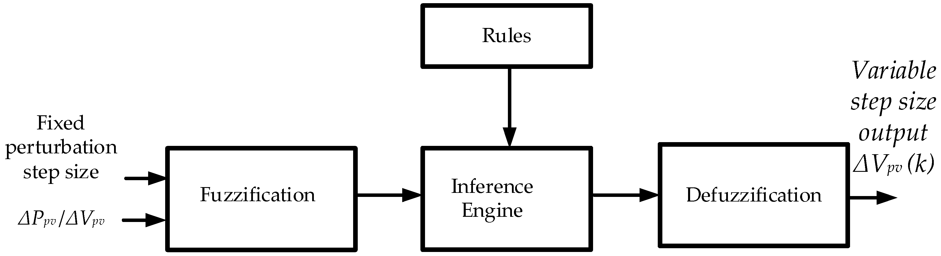
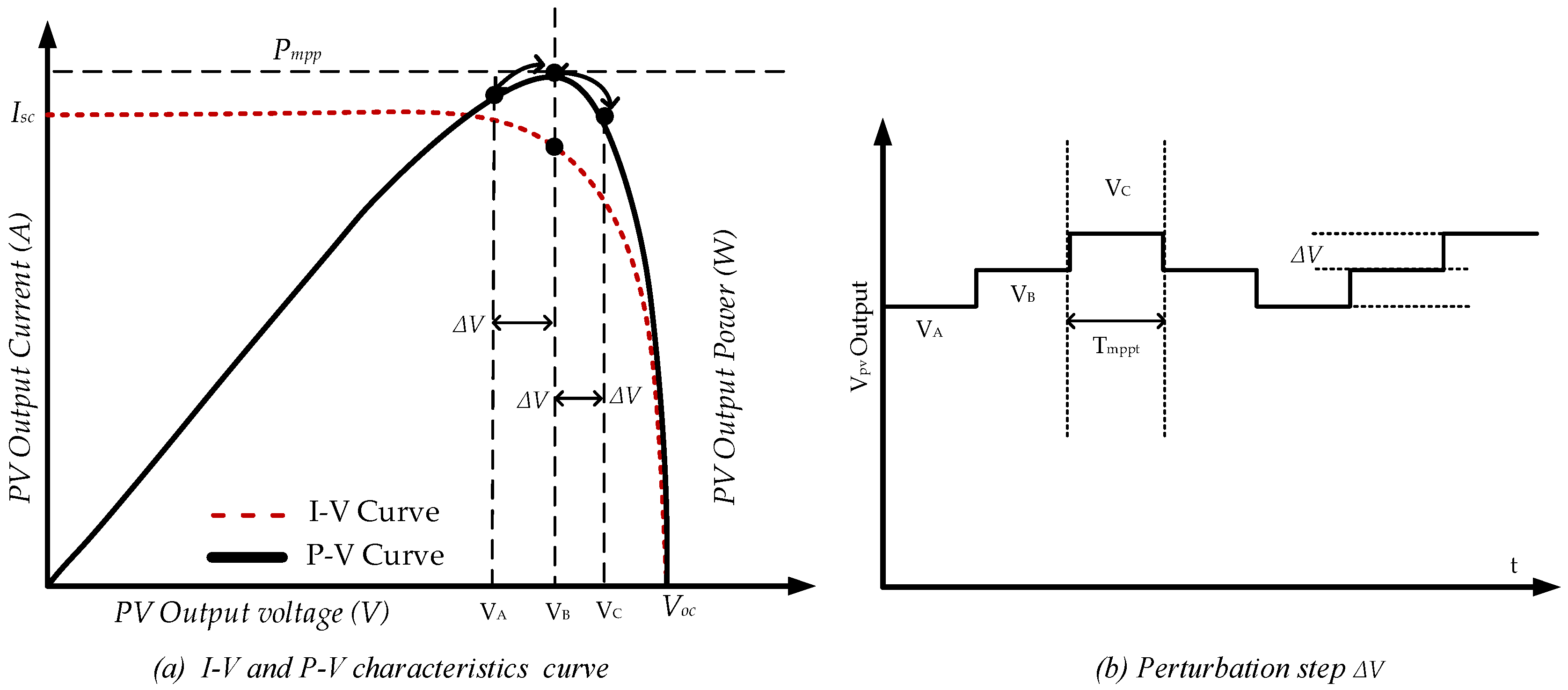
3. Proposed Fuzzy Logical Based Variable Step Size P&O MPPT Algorithm

As conventional P&O method runs typically on fixed step size perturbation, there is a conflict between minimizing oscillation of PV array output power around MPP and convergence of rising time towards MPP when using a fixed step size MPPT. A big step size ensures a faster dynamic response to a sudden change in solar irradiance, but leads to excessive steady state oscillation of the PV array output power around MPP and results in power loss. Small step size ensures less oscillation of PV array output power around MPP but leads to a slower dynamic response to a sudden change in solar irradiance. Therefore, a variable step size MPPT will be necessary to ensure small steady-state oscillations and fast dynamic response. In this paper, the fuzzy logic principle was applied to tune the step size for a P&O MPPT algorithm to overcome the limitations characterized with the conventional fixed step size P&O MPPT. Figure 2 shows the flowchart of the proposed fuzzy logic-based variable step size P&O MPPT algorithm. The efficiency of the MPPT algorithm is defined by Equation (2) where Pactual represents the power produced by the PV array under the control of the MPPT and Pmax is the real maximum power the PV array can produce under the given irradiance and temperature.
η M P P T = 0 t p a c t u a l ( t ) d t 0 t P max ( t ) d t
Ipv and Vpv are the terminal current and voltage of the PV array. With the proposed variable step size P&O MPPT algorithm, the variable step size was determined by a fuzzy logic algorithm to allow the PV array operating point to be automatically tuned by providing a variable step size reference voltage ∆Vpv to the connected power converter. Mamdani ‘s fuzzy logic rule-based method with a structure of Max-Min operation was used to determine the variable step size control action. The fuzzy logic controller consists of four parts as shown in Figure 3. The controller was designed with ”if” and ”then” format and has 25 rules. Furthermore, the labels of the fuzzy were set as: positive very small (PVS), positive small (PS), positive medium (PM), positive high (PH) and positive very high (PVH) respectively as shown in Table 1.
There are two inputs to the fuzzy logic controller; the first is the fixed perturbation step size of the PV voltage. The second input is the instantaneous measured slope PV power (k) where P(k) = Ipv(kVpv(k), ΔP(k) = ∆Ppv(k) − ∆Ppv(k − 1) and ∆Vpv (k) = Vpv(k) − Vpv (k − 1).
The fuzzification block evaluates the fixed perturbation step size and the measured slope of the P-V curve according to the rules in Table 1. and inference is carried out based on the sets of rules. The fuzzy sets µc resulting from the inference is mapped to a crisp output using the membership functions Figure 4, in the defuzzification phase to form the variable step size of the controller control signal.
The output variable step size of the controller ∆Vpv(k) is the prescribed conclusion of each of the 25 rules implemented in the fuzzy logic controller. With two inputs and one output in the design of the fuzzy logic controller, the input-output mapping is a surface which is called the control viewer surface. Figure 5 shows a mesh plot of the control viewer surface input and output mapping relationship between fixed perturbation voltage step size and the instantaneous measured PV curve slope S(k) on the premise side, and the control action output variable step size ∆Vpv(k) on the vertical side, resulting from the 25 rules in Table 1.

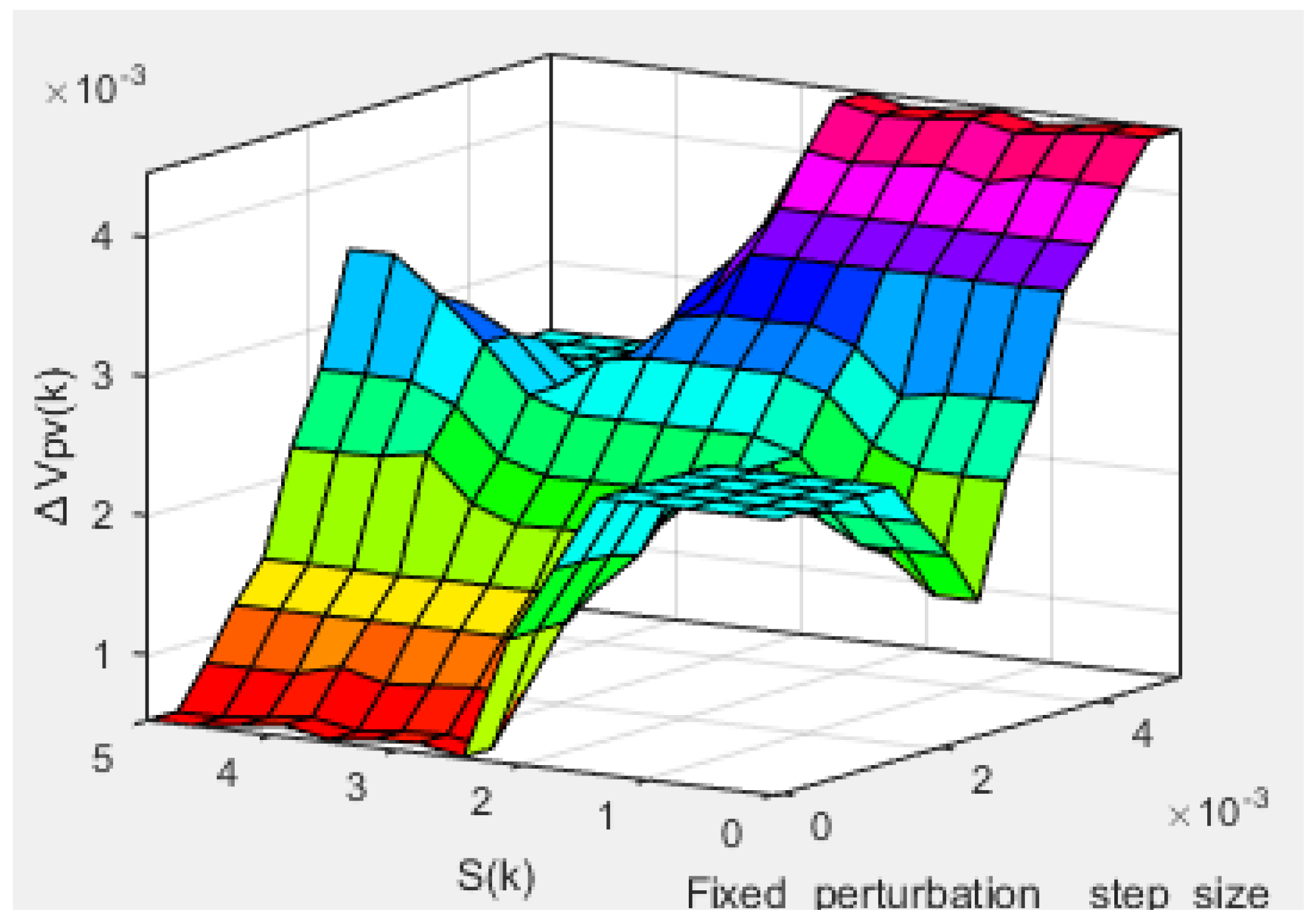
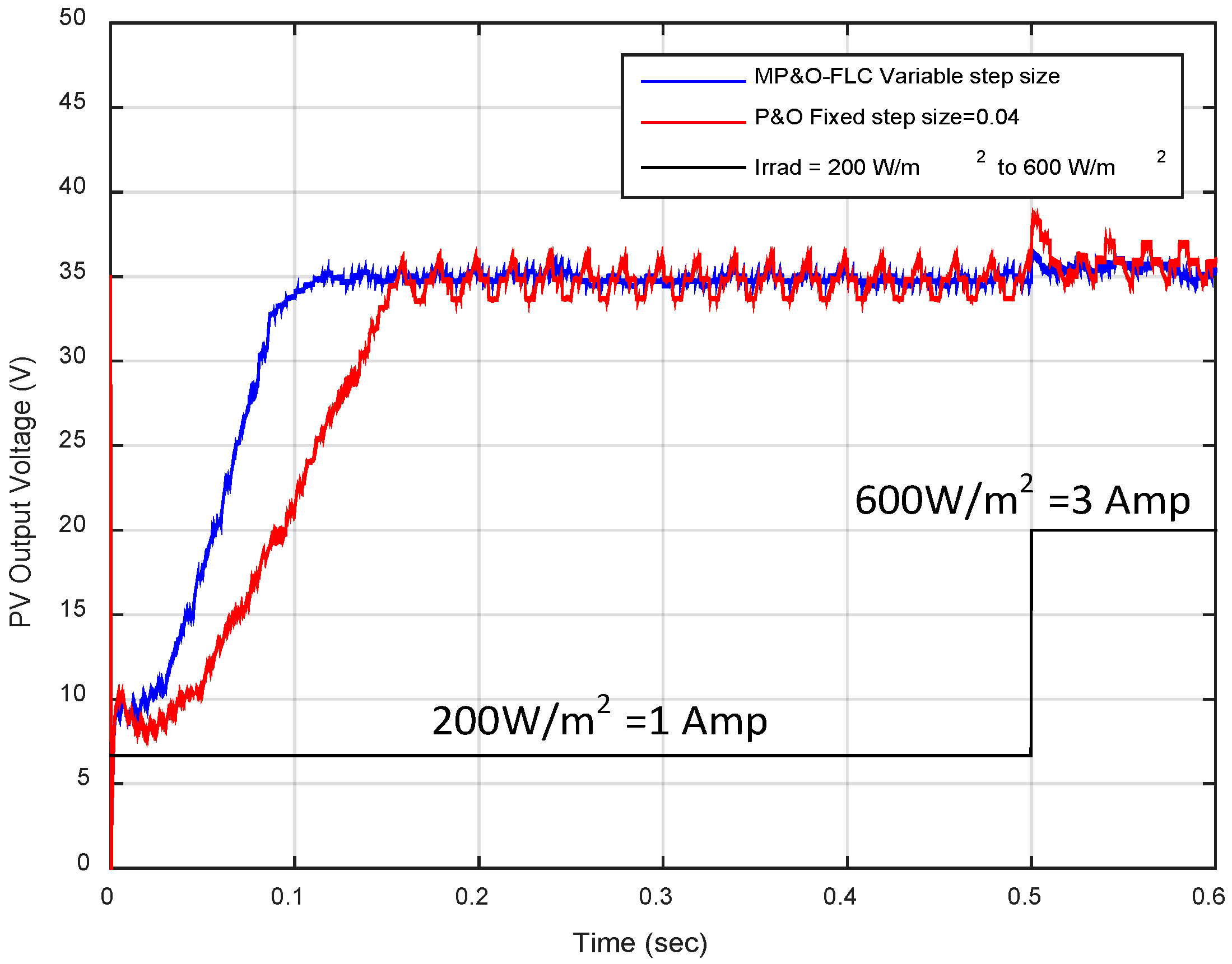
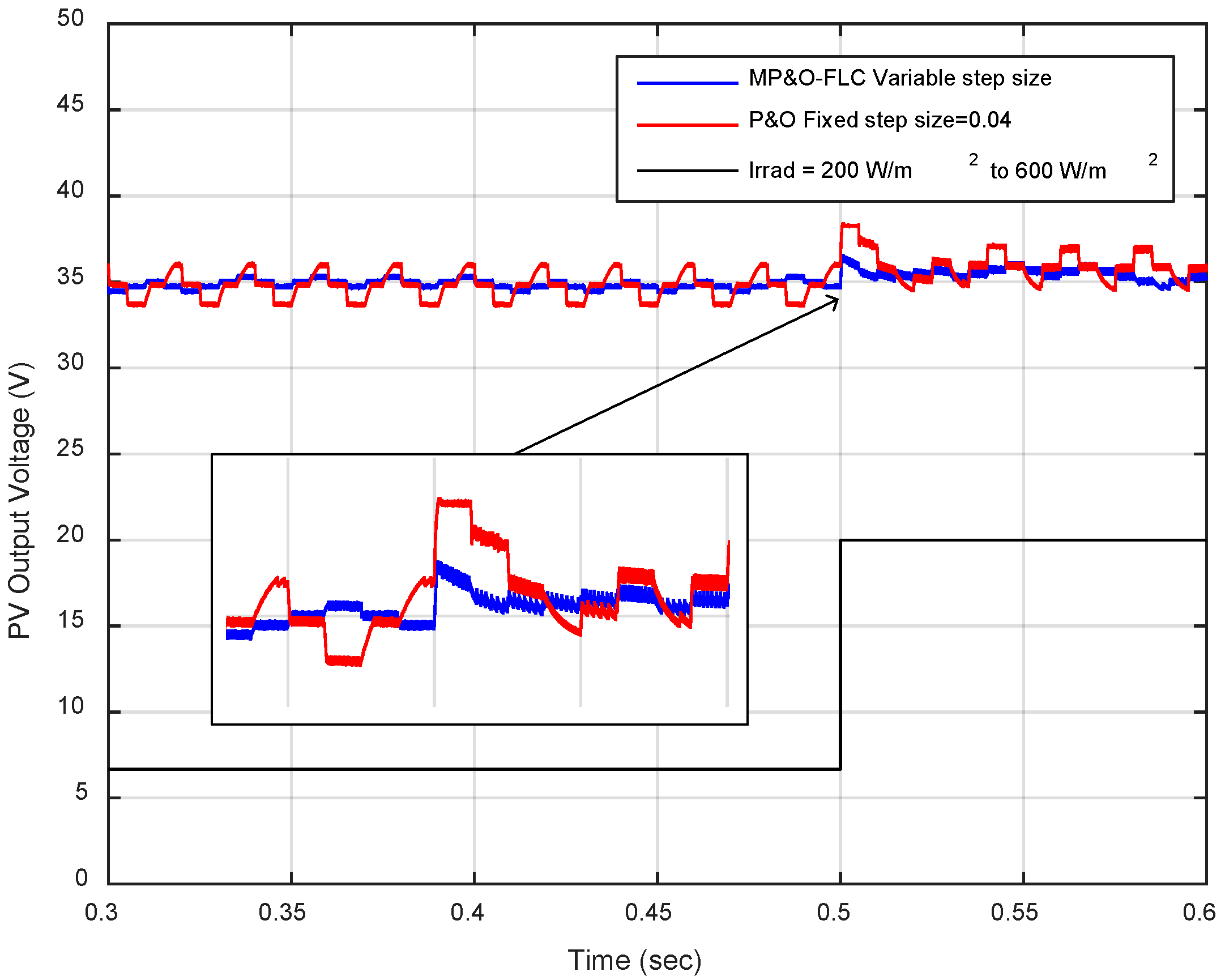
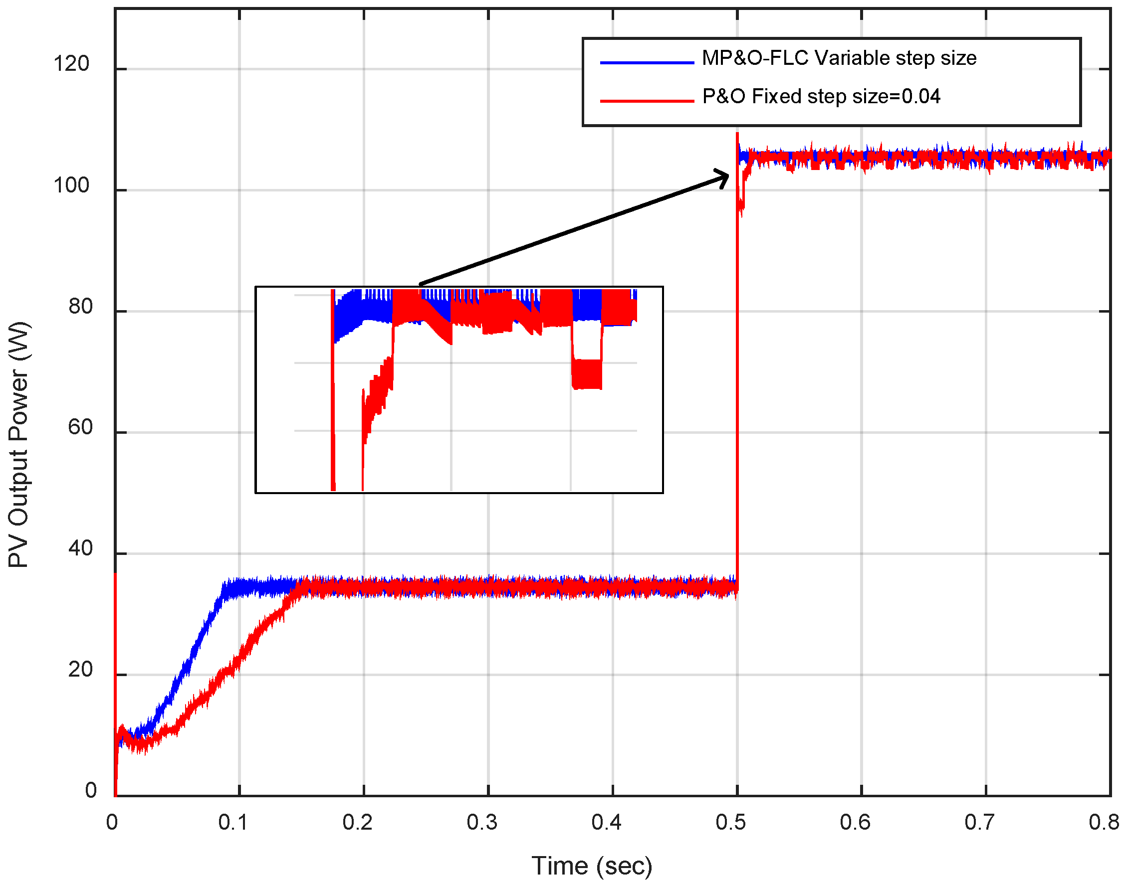
3.1. Simulation Results of the Proposed Variable Step Size P&O MPPT Algorithm

A fixed step size P&O MPPT and the proposed fuzzy logic controller (FLC)-based variable step size P&O MPPT were simulated and compared using MATLAB Simulink. The tracking efficiency in steady state for the conventional P&O with fixed step size voltage and the Proposed Modified P&O based on fuzzy logic variable step size have a small deference of 0.38% efficiency in favor of the Modified P&O based on fuzzy logic variable step size using Equation (2).
Figure 6 shows the simulated PV output voltage with the fixed step size P&O MPPT and the proposed FLC-based variable step size P&O MPPT. The fixed step size was set at ΔV = 0.04 and a perturbation frequency of 200 Hz (the perturbation period ΔT mppt = 5 ms), with a sudden step change in irradiance from 200 W/m2 to 600 W/m2. The result indicates that the FLC-based variable step size P&O MPPT have a faster dynamic response. The convergence of rising time towards maximum power point gives a settling time of 0.11 s compared with the fixed step size P&O MPPT with a step size of ΔV = 0.04 (scale down value) with a settling time of 0.16 s. It also shows that the proposed MPPT with a variable FLC step size has a lower oscillation of PV output voltage around the maximum power point under steady-state conditions when compared with the fixed step size P&O MPPT which have more oscillations of PV output voltage around the maximum power point under steady-state conditions.
Furthermore, Figure 7, shows the PV voltage change of the proposed FLC-based variable step size MPPT and the fixed step size P&O MPPT due to a step change in irradiance from 200 W/m2 to 600 W/m2. The proposed MPPT has a faster transient response in contrast with the fixed step size P&O MPPT.
Figure 8 and Figure 9 show the PV output current and PV output power for the proposed MPPT and a P&O MPPT with fixed step size of ΔV = 0.04 respectively. Faster transient response was found with the proposed MPPT controller.

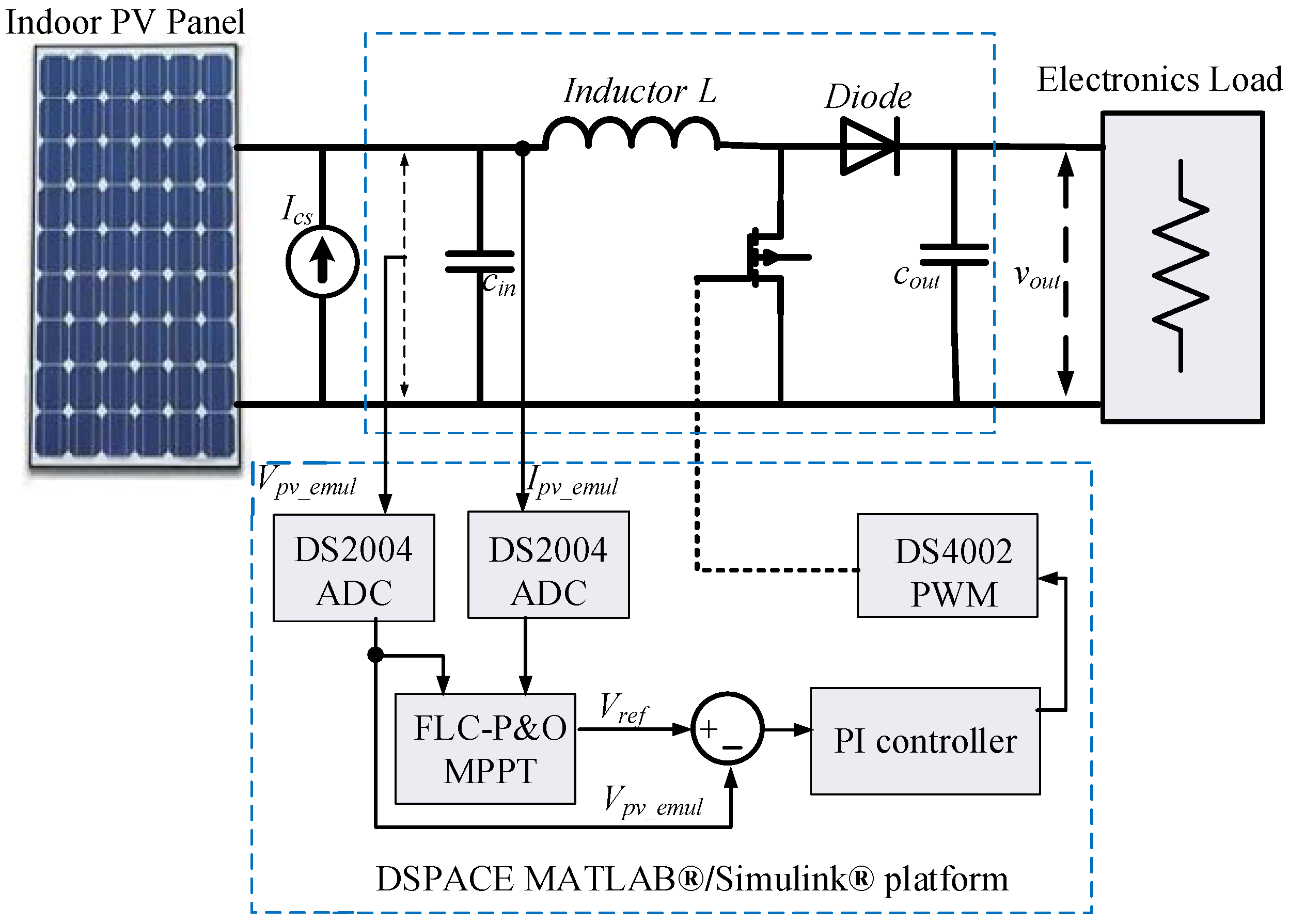
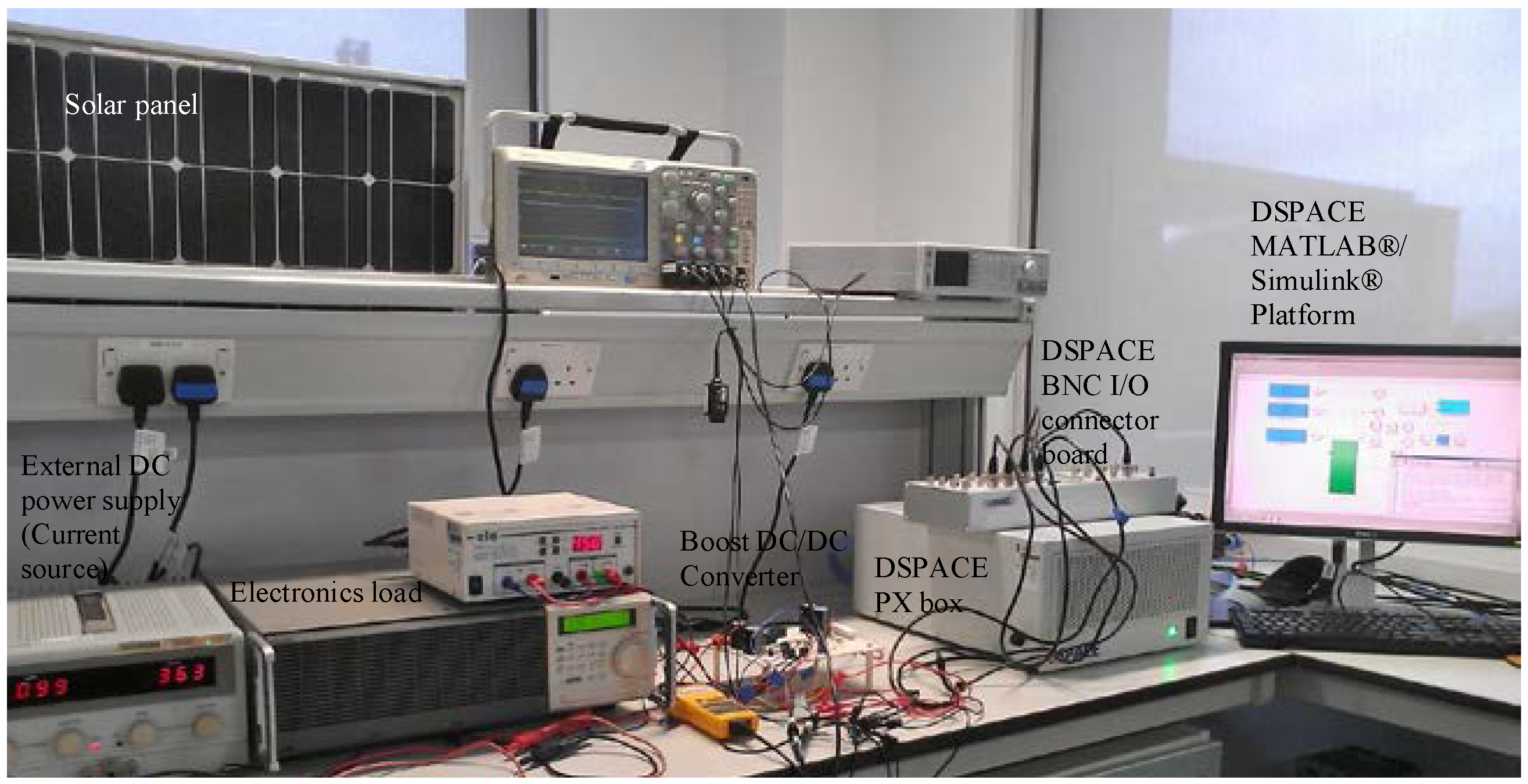
4. Experiment System Setup for Testing the MPPT Algorithm

The block diagram of the experimental test system for testing MPPT algorithms is shown in Figure 10. It consists of four main parts: the PV source, the boost DC-DC converter, dSPACE-based MPPT and the DC-DC converter controller as well as the electronics load. The experiment set-up is shown in Figure 11.

4.1. Boost DC-DC Converter

In the experiment system, the emulated PV source was connected to a boost DC-DC converter and feed to the power to the electronics load. The boost DC-DC converter was constructed by using an inductor, a MOSFET as the power switch, power diode, and input/output capacitors as shown in Figure 10, where a 1.5 kW electronics load was employed as the load and the voltage was regulated at 60 V. The terminal voltage of the emulating PV source Vpv is controlled by the boost DC-DC converter. The theoritical relationship of the PV voltage and the output voltage is expressed as Vpv = Vo(1 − D), where D is the duty cycle of the switching device. By regulating the duty cycle, the required PV terminal voltage can be achieved. The switching frequency of the boost DC-DC converter hardware is set to 20 kHz; this was implemented using hardware-in-the-loop simulations and rapid control prototyping dSPACE MATLAB®/Simulink® PC-based simulation platform Modular Hardware/DS4002 Timing and Digital I/O Board to generate the PWM pulse digital signal for the emulating system shown in Figure 11. The boost converter captures energy generated from the connected PV source and transfers it to the resistive load. The boost DC-DC design parameter is given in Table 2. The same parameters were also implemented in the emulated PV system using MATLAB/Simulink system tool box to obtain the simulation results in Section 3.1.

4.2. dSPACE-Based MPPT Controller Implementation

The proposed FLC-based variable step size P&O MPPT algorithm was implemented via dSPACE rapid control prototyping (RCP) in a real-time environment, which was developed within MATLAB® and Simulink®. An RTI (real-time interface) block of Modular Hardware/DS2004 High-Speed A/D Board was used in measuring the output current (Ipv) and voltage(Vpv) of the emulated PV source as shown in Figure 10. The measured Ipv_emul and Vpv_emul was then used in implementing the MPPT algorithm. The instantaneous measured Ipv and Vpv were scaled down using a current and voltage measurement circuit on the DC-DC boost converter because the signal applied to the dSPACE Analogue to Digital (ADC) channel must be in the range of −10 V to +10 V. To get the actual sensed measured value rather than the scaled down value, the gains for the current and voltage are 2.6 and 28 respectively.

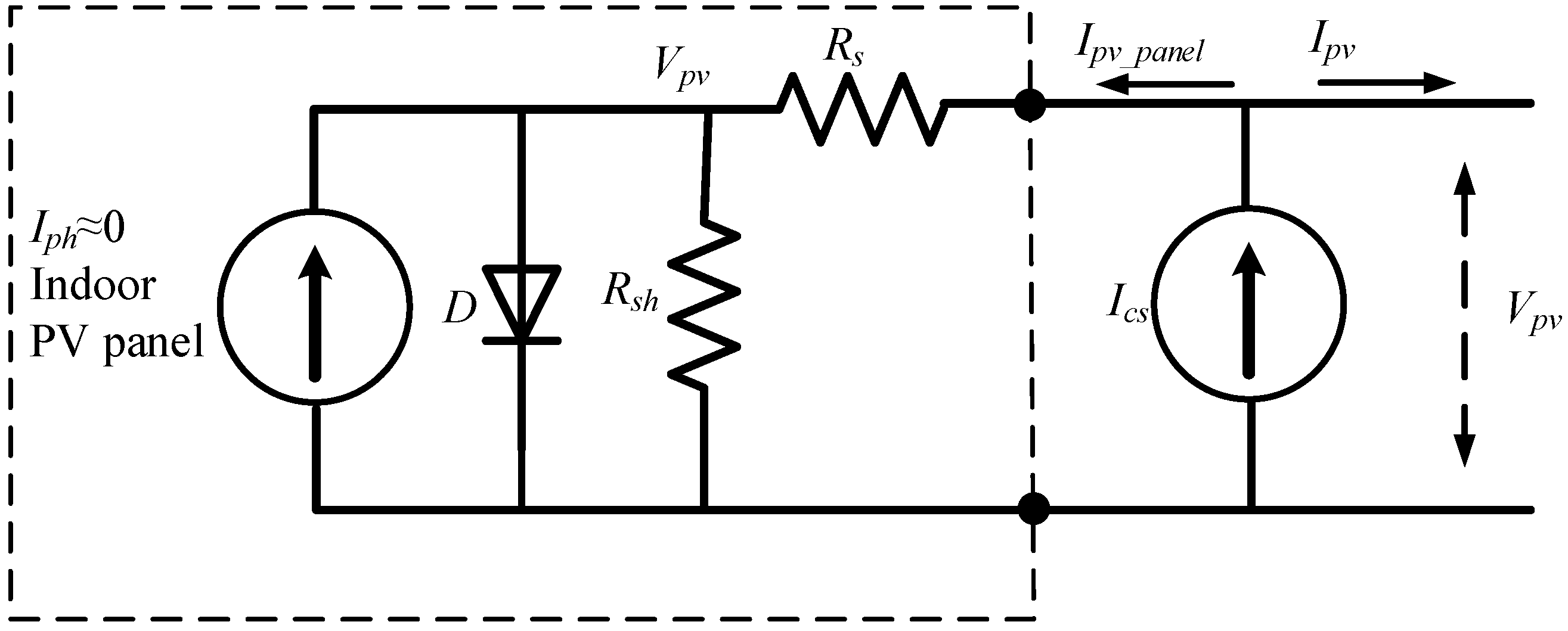
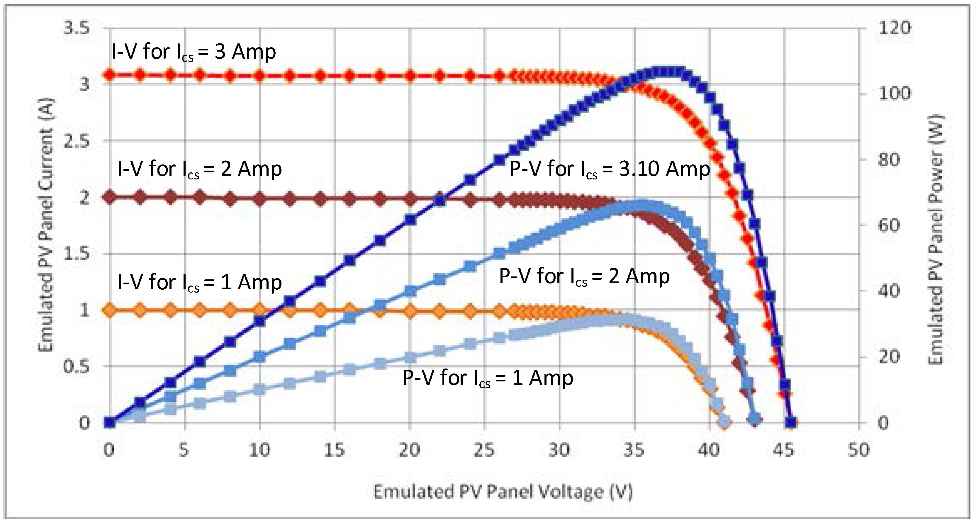
4.3. The Emulated PV Source

There are two major approaches for testing MPPT algorithms and PV converters. The first test involves using an actual outdoor installed PV testing at high power conditions. However, it requires outdoor space and it is also hard to repeat testing conditions due to dependence on direct solar irradiance. In this paper, an emulated PV source was proposed and constructed for testing the MPPT algorithms. The emulated PV source was built by connecting a 175 W commercial PV panel (STP175S-24/Ac) in parallel with a 360 W DC power supply (ISO-TECH-ISO1603D) which operates in a constant current mode to mimic the emulated PV panel.
In darkness or indoor conditions, no current or minimal current is generated. The 360 W DC power supply (ISO-TECH-ISO1603D) operating in constant current source mode was employed to inject an external current source to emulate the photo-generated current. The equivalent circuit is presented in Figure 12, where Ics represent the external excitement current. For a conventional commercial PV panel, the external excitement current will be injected into the solar panel through the internal series resistor.
In an indoor condition, the photocurrent Iph ≈ 0, therefore the I-V characteristics of the emulated PV panel are expressed by Equations (3)–(5) respectively:
I p v = I c s I 0 ( e V p v I p v R s N s V t 1 ) I s h
V p v = ( I c s I p v ) R s + n V t ln ( I c s I p v ) I s h + I 0 I 0
I s h = V p v ( I c s I p v ) R s R s h
where, ICS represents the external excitement current to emulate the photo-generated current at direct sunlight, I0 represents the dark saturation current, Rs represents the panel series resistance, Rsh represents the panel parallel resistance, Ns is the number of cells connected in series, Vt represents the junction thermal voltage given by equation VT = KTc/q, k is Boltzmann’s constant 1.381 × 10⁻²³ J/K and q represents the elementary charge 1.602 × 10⁻¹⁹ C. The parameters of the solar panel under standard testing condition (STC) are presented in Table 3. STC is an industry-wide standard under which solar panels are tested i.e., by applying the following test coditions (irradiance 1000 W/m2, module temperature 25 °C and an air mass of 1.5 (AM1.5)) [29]. The electrical characteristics of the proposed emulated PV source using different excitement currents is shown in Figure 13.

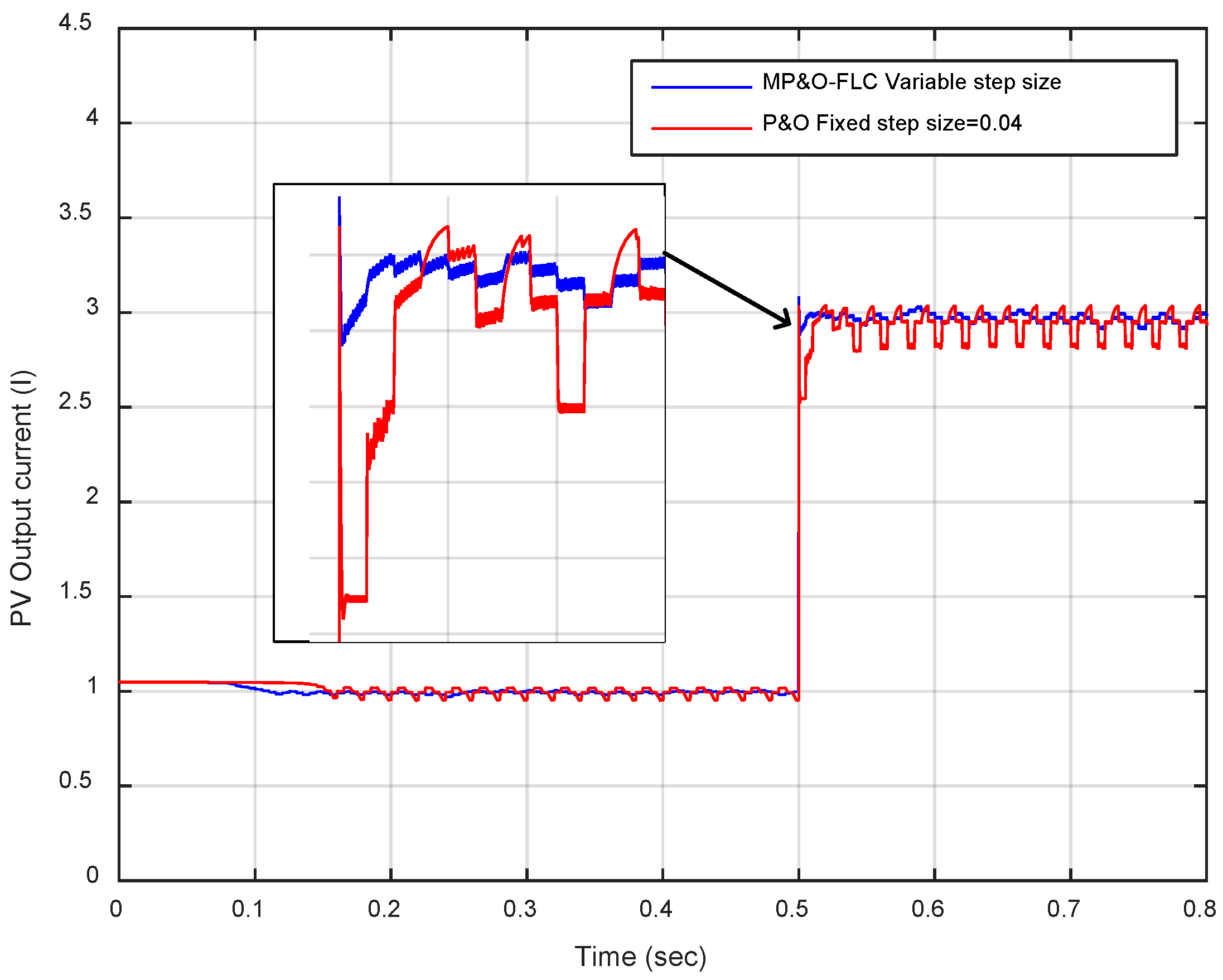
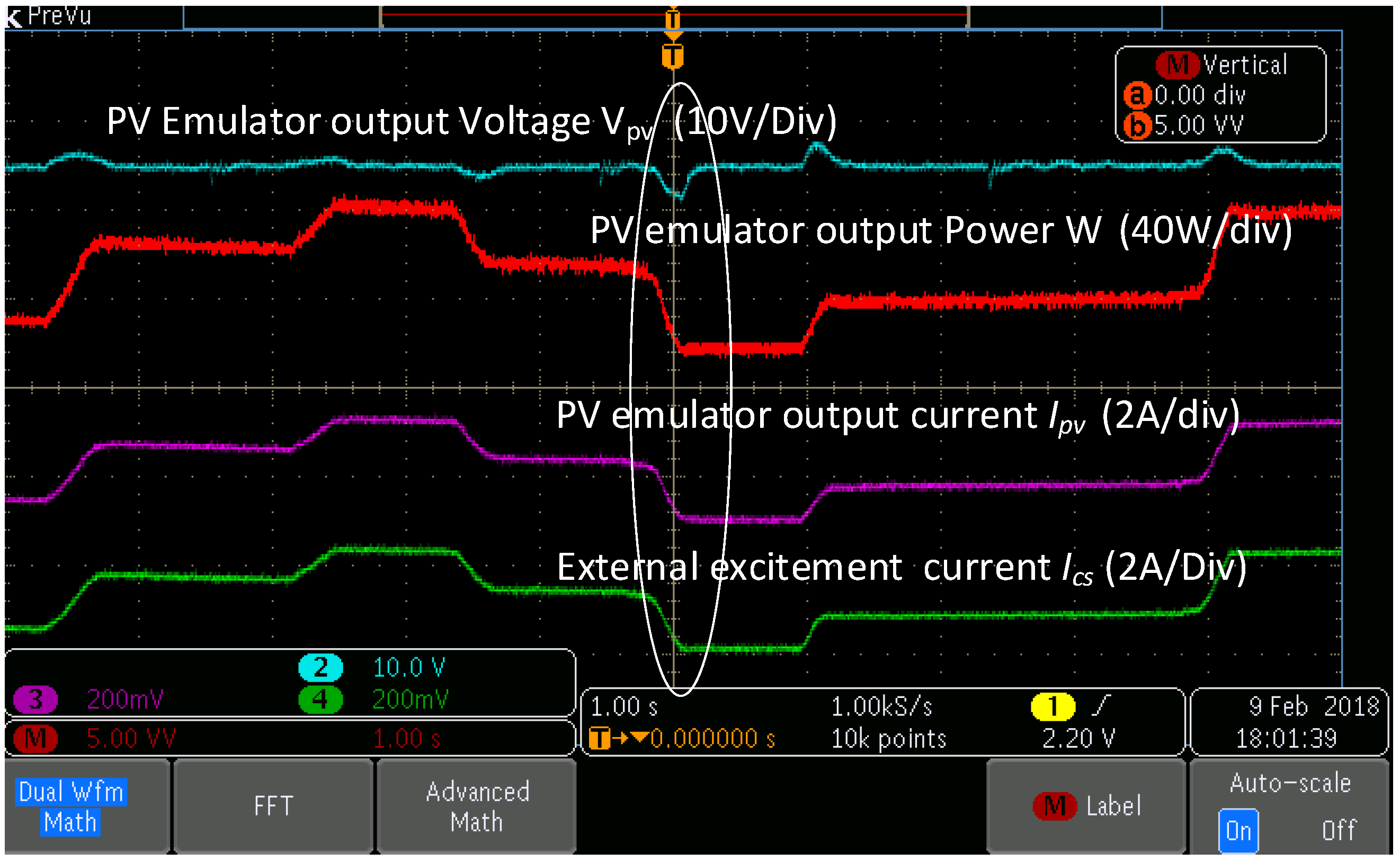
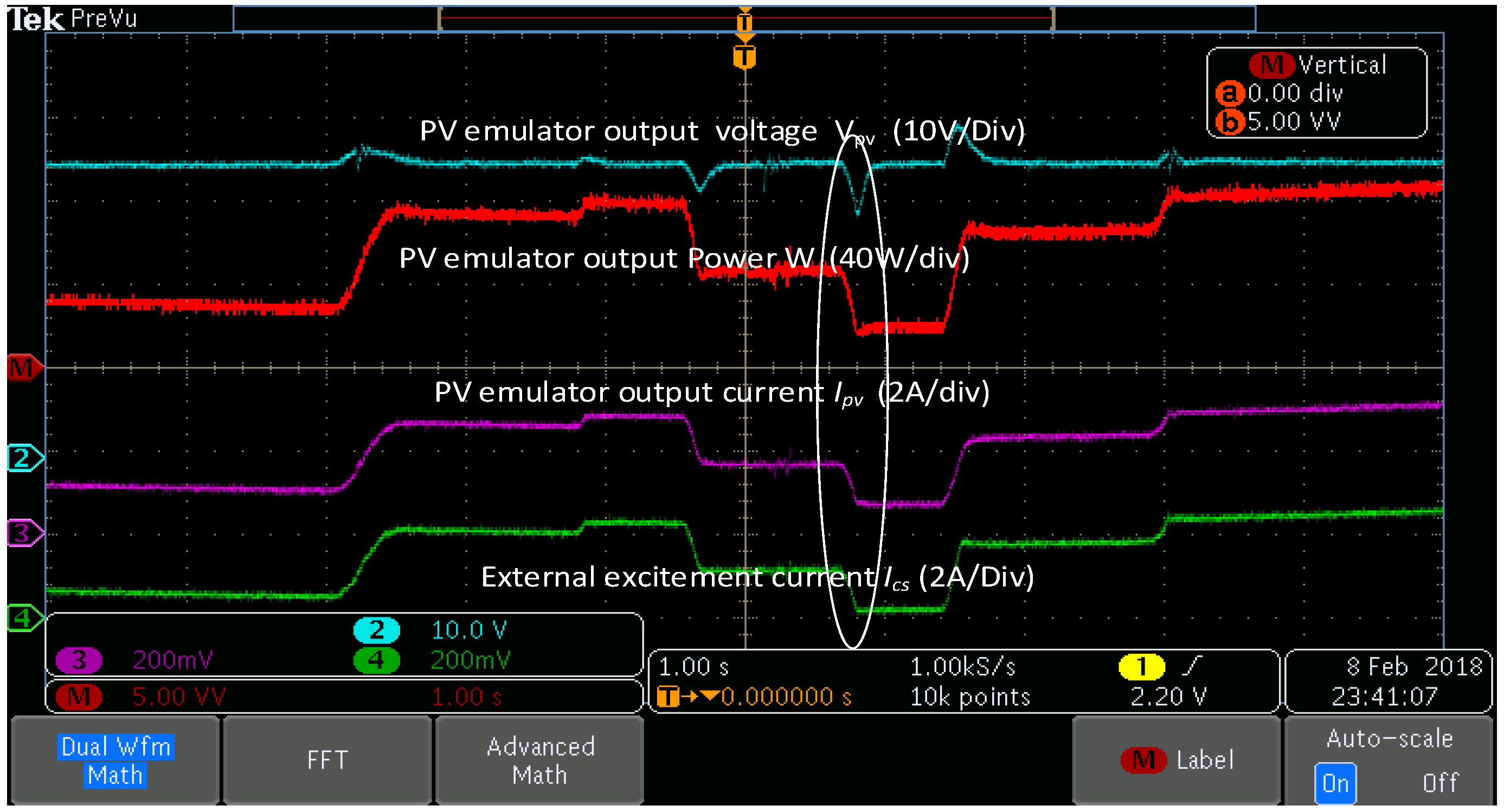
4.4. Experimental Results

In steady state, the output voltage of the DC-DC converter was clamped at constant DC value of 60 V by the connected electronics load. Before the start-up of the boost DC-DC converter (no switching action was applied to the switching device) the DC link output capacitor Co was charged through the inductor and diode by the emulated PV source. The charging current was naturally limited by the connected current source, so no extra power resistor is required in the charging circuit.
Both fixed step size P&O MPPT and the proposed FLC-based variable step size P&O MPPT were tested with a perturbation frequency of 200 Hz (i.e., perturbation time step ΔTmppt = 5 ms).
Figure 14 shows the proposed P&O-FLC variable step size MPPT algorithm experimental test results with varying external excitement current emulating the variable photo-generated current. The steady-state PV terminal voltage of the emulated PV source is controlled at by the DC-DC boost converter. It observed that with excitement current Ics of 1 Amp (equivalent to 200 W/m2) the PV output voltage is continuously oscillating around the voltage (35.48 V) at the maximum power point.
Furthermore, Figure 15 presents the fixed step size P&O MPPT experimental test results which have a fixed perturbation voltage step size of ΔV = 0.04 (scale down value), the result shows the varying current source currents emulating the variable photo-generated current and the steady state PV terminal voltage of the emulated PV system. It observed that for an emulated generated current of excitement current Ics of 1 Amp which is equivalent to 200 W/m2 the PV output voltage is continuously oscillating around the voltage (34.40 V) at MPP. It is also observed that the proposed FLC variable step size MPPT shows a better dynamic transient response with a sudden change in excitement current Ics of 1 Amp (equivalent 200 W/m2) to Ics of 3 Amp (equivalent 600 W/m2) as shown on the marked oval shape in Figure 14 and Figure 15.
As the change of the solar irradiance was emulated by tuning the external excitement current via tuning the external current source knob manually, the step changes in solar irradiance was not able to be emulated as only ramp changes can be done with manually tuning of the knob of the current source. As a result, it is hard to see the transient difference between the two MPPT algorithms with the ramp changes in the solar irradiance in the practical experiment. This would be investigated in future experiments. Experimental results show that the DSPACE-based control system was effective for the investigation of real-time control algorithms.
However, the difference of the conventional fixed step size P&O MPPT and fuzzy logic-based variable step size P&O MPPT can be seen from the simulation results shown in Figure 6, Figure 7, Figure 8 and Figure 9. For the step change s in solar irradiance. Based on the simulation test results shown in (Figure 6, Figure 7, Figure 8 and Figure 9), fuzzy logic-based variable step size P&O MPPT has faster and smaller power oscillations then the conventional fixed step size P&O maximum power point tracking.

5. Conclusions

In this paper, a Modified Perturb & Observe (P&O) Maximum power point tracking (MPPT) algorithm using a fuzzy logic controller with variable step size was proposed and implemented in order to overcome the limitations associated with conventional fixed step size P&O MPPT tracking method.
The proposed Modified P&O MPPT technique was verified by simulation circuit; simulation results show that the proposed method provides a faster response for step changes in irradiance and fewer steady state oscillations around the maximum power point. The tracking efficiency in steady state for the conventional P&O with fixed step size voltage and the Proposed Modified P&O based on fuzzy logic variable step size have a small difference in tracking efficiency of 0.38% in favor of the Modified P&O based on fuzzy logic variable step size.
A solar emulator-based PV experiment system using boost DC-DC converter was constructed and used for testing the proposed MPPT algorithm. Both conventional fixed step size and fuzzy logical-based variable step size P&O MPPT algorithms were tested. Test results show that both MPPT algorithms can track the actual maximum power point well when the solar irradiance varies. Experimental results show that the DSPACE-based control system was effective for the investigation of real-time control algorithms.
The proposed fuzzy logic variable step size-based P&O MPPT algorithm can resolve the conflict between minimizing oscillation of PV array output power around maximum power point and convergence of rising time towards maximum power point, for which some of the setbacks associated with are using a fixed step size MPPT.

Author Contributions

Conceptualization, J.M. and Z.Z.; Methodology, J.M.; Software, J.M.; Validation, J.M. and Z.Z.; Formal Analysis, J.M.; Investigation, J.M.; Data Curation, J.M.; Writing-Original Draft Preparation, J.M.; Writing-Review & Editing, J.M. and Z.Z.; Supervision, Z.Z.

Conflicts of Interest

The authors declare no conflict of interest.

References

  1. Owusu, P.A.; Asumadu-Sarkodie, S. A review of renewable energy sources, sustainability issues and climate change mitigation. Cogent Eng. 2016, 3, 1167990. [Google Scholar] [CrossRef]
  2. Panwar, N.L.; Kaushik, S.C.; Kothari, S. Role of renewable energy sources in environmental protection: A review. Renew. Sustain. Energy Rev. 2011, 15, 1513–1524. [Google Scholar] [CrossRef]
  3. Munawwar, S.; Ghedira, H. A review of renewable energy and solar industry growth in the GCC region. Energy Procedia 2014, 57, 3191–3202. [Google Scholar] [CrossRef]
  4. Saridakis, S.; Koutroulis, E.; Blaabjerg, F. Optimal design of modern transformerless PV inverter topologiesd. IEEE Trans. Energy Convers. 2013, 28, 394–404. [Google Scholar] [CrossRef]
  5. Serban, E.; Paz, F.; Ordonez, M. Improved PV Inverter Operating Range Using a Miniboost. IEEE Trans. Power Electron. 2017, 32, 8470–8485. [Google Scholar] [CrossRef]
  6. Chakraborty, S.; Razzak, M.A.; Chowdhury, M.S.U.; Dey, S. Design of a transformer-less grid connected hybrid photovoltaic and wind energy system. In Proceedings of the 2014 9th International Forum on Strategic Technology (IFOST 2014), Cox’s Bazar, Bangladesh, 21–24 October 2014; pp. 400–403. [Google Scholar]
  7. Femia, N.; Petrone, G.; Spagnuolo, G.; Vitelli, M. Optimization of perturb and observe maximum power point tracking method. IEEE Trans. Power Electron. 2005, 20, 963–973. [Google Scholar] [CrossRef]
  8. Ahmed, J.; Ahmed, J.; Member, S.; Salam, Z. A Modified P&O Maximum Power Point Tracking Method with Reduced Steady State Oscillation and Improved Tracking Efficiency. IEEE Trans. Sustain. Energy 2016, 3029, 1–10. [Google Scholar]
  9. Kumar, N.; Hussain, I.; Singh, B.; Panigrahi, B.K. Framework of Maximum Power Extraction From Solar PV Panel Using Self Predictive Perturb and Observe Algorithm. IEEE Trans. Sustain. Energy 2018, 9, 895–903. [Google Scholar] [CrossRef]
  10. Lian, K.L.; Jhang, J.H.; Tian, I.S. A maximum power point tracking method based on perturb-and-observe combined with particle swarm optimization. IEEE J. Photovolt. 2014, 4, 626–633. [Google Scholar] [CrossRef]
  11. Menniti, D.; Pinnarelli, A.; Brusco, G. Implementation of a novel fuzzy-logic based MPPT for grid-connected photovoltaic generation system. In Proceedings of the 2011 IEEE PES Trondheim PowerTech: The Power of Technology for a Sustainable Society (POWERTECH 2011), Trondheim, Norway, 9–23 June 2011. [Google Scholar]
  12. Tey, K.S.; Mekhilef, S. Modified incremental conductance MPPT algorithm to mitigate inaccurate responses under fast-changing solar irradiation level. Sol. Energy 2014, 101, 333–342. [Google Scholar] [CrossRef]
  13. Schofield, D.M.K.; Foster, M.P.; Stone, D.A. Low-cost solar emulator for evaluation of maximum power point tracking methods. Electron. Lett. 2011, 47, 208. [Google Scholar] [CrossRef]
  14. Punitha, K.; Devaraj, D.; Sakthivel, S. Artificial neural network based modified incremental conductance algorithm for maximum power point tracking in photovoltaic system under partial shading conditions. Energy 2013, 62, 330–340. [Google Scholar] [CrossRef]
  15. Daraban, S.; Petreus, D.; Morel, C. A novel MPPT (maximum power point tracking) algorithm based on a modified genetic algorithm specialized on tracking the global maximum power point in photovoltaic systems affected by partial shading. Energy 2014, 74, 374–388. [Google Scholar] [CrossRef]
  16. Manickam, C.; Raman, G.P.; Raman, G.R.; Ganesan, S.I.; Chilakapati, N. Fireworks enriched P&O algorithm for GMPPT and detection of partial shading in PV systems. IEEE Trans. Power Electron. 2017, 32, 4432–4443. [Google Scholar]
  17. Zhao, J.; Zhou, X.; Gao, Z.; Ma, Y.; Qin, Z. A novel global maximum power point tracking strategy (GMPPT) based on optimal current control for photovoltaic systems adaptive to variable environmental and partial shading conditions. Sol. Energy 2017, 144, 767–779. [Google Scholar] [CrossRef]
  18. Esram, T.; Chapman, P.L. Comparison of Photovoltaic Array Maximum Power Point Tracking Techniques. IEEE Trans. Energy Convers. 2007, 22, 439–449. [Google Scholar] [CrossRef]
  19. Sahu, T.P.; Dixit, T.V. Modelling and analysis of perturb and observe and incremental conductance MPPT algorithm for PV array using Ċuk converter. In Proceedings of the 2014 IEEE Students’ Conference on Electrical, Electronics and Computer Science (SCEECS 2014), Bhopal, India, 1–2 March 2014. [Google Scholar]
  20. Ahmed, J.; Salam, Z. An improved perturb and observe (P&O) maximum power point tracking (MPPT) algorithm for higher efficiency. Appl. Energy 2015, 150, 97–108. [Google Scholar]
  21. Femia, N.; Petrone, G.; Spagnuolo, G. Optimizing Sampling Rate of P & O MPPT Technique. In Proceedings of the 35th Annual IEEE Power Electronics Specialists Conference, Aachen, Germany, 20–25 June 2004; pp. 1945–1949. [Google Scholar]
  22. Baraskar, S.; Jain, S.K.; Padhy, P.K. Fuzzy logic assisted P and O based improved MPPT for photovoltaic systems. In Proceedings of the International Conference on Emerging Trends in Electrical, Electronics and Sustainable Energy Systems (ICETEESES 2016), Majhitar, India, 17–18 December 2016; pp. 250–255. [Google Scholar]
  23. Yüksek, G.; Mete, A.N. A hybrid variable step size MPPT method based on P&O and INC methods. In Proceedings of the 2017 10th International Conference on Electrical and Electronics Engineering (ELECO), Bursa, Turkey, 30 November–2 December 2017; pp. 949–953. [Google Scholar]
  24. Harrag, A.; Messalti, S. Variable step size modified P&O MPPT algorithm using GA-based hybrid offline/online PID controller. Renew. Sustain. Energy Rev. 2015, 49, 1247–1260. [Google Scholar]
  25. Kollimalla, S.K.; Member, S.; Mishra, M.K.; Member, S. Variable Perturbation Size Adaptive P&O MPPT Algorithm for Sudden Changes in Irradiance. IEEE Trans. Sustain. Energy 2014, 5, 718–728. [Google Scholar]
  26. Jusoh, A.; Alik, R.; Guan, T.K.; Sutikno, T. MPPT for PV System Based on Variable Step Size P&O Algorithm. Telkomnika 2017, 15, 79–92. [Google Scholar]
  27. Hohm, D.P.; Ropp, M.E. Comparative study of maximum power point tracking algorithms. Prog. Photovolt. Res. Appl. 2003, 11, 47–62. [Google Scholar] [CrossRef]
  28. Hohm, D.P.; Ropp, M.E. Comparative study of maximum power point tracking algorithms using an experimental, programmable, maximum power point tracking test bed. In Proceedings of the 28th IEEE Photovoltaic Specialists Conference, Anchorage, AK, USA, 15–22 September 2000; pp. 1699–1702. [Google Scholar]
  29. Elibol, E.; Özmen, Ö.T.; Tutkun, N.; Köysal, O. Outdoor performance analysis of different PV panel types. Renew. Sustain. Energy Rev. 2017, 67, 651–661. [Google Scholar] [CrossRef]
Figure 1. P&O MPPT algorithm operation.
Energies 11 01340 g001
Figure 2. Fuzzy Logical Based variable step size P&O MPPT algorithm.
Energies 11 01340 g002
Figure 3. Fuzzy logic controller block diagram.
Energies 11 01340 g003
Figure 4. The membership function of the proposed fuzzy logic controller for the variable step size MPPT algorithm (a) fixed step size perturbation; (b) PV curve slope S(k); (c) variable step ∆Vpv(k).
Energies 11 01340 g004
Figure 5. Mesh plot of the input and output mapping of the relationship between the fixed perturbation voltage step size and the measured PV curve slope S(k) and the output variable step ∆Vpv(k).
Energies 11 01340 g005
Figure 6. Comparison of conventionally fixed step size P&O MPPT and the proposed FLC-based variable step size P&O MPPT with a startup.
Energies 11 01340 g006
Figure 7. Comparison of PV voltage with fixed step size P&O MPPT and the proposed FLC-based variable step size P&O MPPT with a step change in solar irradiance.
Energies 11 01340 g007
Figure 8. Comparison of PV current with fixed step size P&O MPPT and the proposed FLC-based variable step size P&O MPPT with a step change in solar irradiance.
Energies 11 01340 g008
Figure 9. Comparison of PV power with fixed step size P&O MPPT and the proposed FLC-based variable step size P&O MPPT with a step change in solar irradiance.
Energies 11 01340 g009
Figure 10. Block diagram of the experiment system for testing the MPPT algorithm.
Energies 11 01340 g010
Figure 11. dSPACE Experimental test system of the MPPT and DC-DC boost converter.
Energies 11 01340 g011
Figure 12. Equivalent circuit of the emulated PV system with a single solar panel.
Energies 11 01340 g012
Figure 13. Measured electrical characteristics of the emulated PV source with excitement different currents.
Energies 11 01340 g013
Figure 14. MP&O fuzzy logic controller Variable step size MPPT Test results with variable current source currents (emulating the variable photo-generated current).
Energies 11 01340 g014
Figure 15. Conventional P&O (fixed step size) MPPT Test results with variable current source currents (emulating the variable photo-generated current).
Energies 11 01340 g015
Table 1. Fuzzy rules table for the MP&O MPPT.
Δe = S(k)PVSPSPMPHPVH
E = Voltage Step
PVSPVHPVSPVSPSPS
PSPVHPVSPVSPSPS
MPPSPSPSPVHPVH
HPPSPVHPSPVSPVH
PVHPVSPVSPVHPHPVH
Table 2. Boost DC-DC converter design parameter.
Boost DC-DC Converter Parameter
Switching frequency20 kHz
Input capacitor220 µF
Output capacitor440 µF
Inductor100 µH
Table 3. The parameters of the solar panel STP175s-24/AC at STC.
Rated Maximum power175 Watts
Voltage at the maximum power point (Vmpp)35.2 Volts
Current at the maximum power point (Impp)4.95 Amp
Short circuit current (Isc)5.2 Amp
Open circuit voltage (Voc)44.2 Volts
Normal operating cell temperature50 °C

