Article

Research on the Robustness of the Constant Speed Control of Hydraulic Energy Storage Generation

1
Energy and Power Engineering College, Lanzhou University of Technology, Lanzhou 730050, China
2
Key Laboratory of Fluid Machinery and Systems, Gansu Province, Lanzhou 730050, China
*
Author to whom correspondence should be addressed.
Energies 2018, 11(5), 1310; https://doi.org/10.3390/en11051310
Submission received: 24 April 2018 / Revised: 17 May 2018 / Accepted: 17 May 2018 / Published: 21 May 2018
(This article belongs to the Section D: Energy Storage and Application)

Abstract

:
Energy storage plays a major role in solving the fluctuation and intermittence problem of wind and the effective use of wind power. The application of the hydraulic accumulator is the most efficient and convenient way to store wind energy in hydraulic wind turbines. A hydraulic energy storage generation system (HESGS) can transform hydraulic energy stored in the hydraulic accumulator into stable and constant electrical energy by controlling the variable motor, regardless of wind changes. The aim of the present study is to design a constant speed control method for the variable motor in the HESGS and investigate the influence of the controller’s main parameters on the resistance of the HESGS to external load power disturbances. Mathematical equations of all components in this system are introduced and an entire system simulation model is built. A double closed-loop control method of the variable motor is presented within this paper, which keeps the motor speed constant for the fixed frequency of electrical power generated by the HESGS. Ultimately, a series of simulations with different proportional gains and integral gains under the environment of changeless load power step are conducted. At the same time, comparison analyses of the experiment and simulation under variable load power step are performed. The results verify the correctness and the usability of the simulation model, and also indicate that the proposed control method is robust to the disturbances of changing load power.

1. Introduction

Due to excessive exploitation and application of traditional energy sources like coal, the whole world must face up to the energy crisis and environmental pollution problems. These problems must been solved by the large-scale employment of renewable energy. With the technological progress in wind turbines in recent years, wind power generation is a good choice to fulfill the ever increasing demand of energy [1]. The global total wind power industry at the end of 2016 was 486.8 GW, representing cumulative market growth of more than 12 percent. Overall, the global wind power industry installed 54.6 GW in 2016. In China, 23,370 MW of new capacity was added to the country’s electricity grid [2].
According to the transmission system adopted by wind turbine, wind turbines are classified scientifically into traditional gear drive, direct-driven without gear box and hydrostatic transmission [3]. In a conventional wind turbine with gear drive, the gearbox is a key component of the wind energy conversion system, which has a higher failure rate and needs regular repairs [4]. Mechanical noise is emitted by the gear box due to the lack of preventative maintenance, which causes annoyances to people living in their vicinity [5,6]. The direct-driven wind turbine without gear box removes the gearbox by replacing it with a permanent magnet generator. However, this is more expensive compared with the generator systems with gearboxes [7]. Wind turbines equipped with hydrostatic transmission are called hydraulic wind turbines. The research and development of hydraulic wind turbines has attracted tremendous attention of researchers around the world, because they present unique advantages such as high power-weight ratio, changing transmission ratio in a timely manner and elimination of the converter system [8]. Nikranjbar established the mathematical model of a wind turbine with variable speed hydrostatic transmission in the MATLAB software. The simulations were achieved under an average wind speeds of 9 and 16 m/s and 12% turbulence intensity wind. The simulation results shown that the hydraulic wind turbine had the great performance [9]. The authors in [10] developed a simulation model for wind turbines with high-pressure hydraulic transmission machinery. They have employed HAWC2 (a state-of-the-art aeroelastic code intended for calculating wind turbine response in the time domain) to perform the dynamic simulation of a 5 MW wind turbine. They found that a hydraulic wind turbine has good performance under changing wind conditions. The authors in [11] have verified the mathematical model of a hydraulic wind turbine with MATLAB and AMESim. They have presented a control strategy to keep the motor speed constant. The simulations and experiments revealed that the control method had efficient speed regulation performance.
Due to the randomness and intermittent nature of natural wind, the output power of wind farms frequently fluctuates, which can affect the stable operation of the power system and lead to a decline in power quality. Consequently, there is equally strong demand for energy storage systems (ESSs). The ESS can store the excess energy captured by a wind turbine and satisfy energy requirements when there is no wind. Wind energy can be transformed into mechanical energy, electric energy, chemical energy and pressure energy, which can be expediently stored in various types of energy storage system [12]. Chudy et al. proposed that a flywheel plant be used as a fully-fledged energy storage system to store wind energy. Algebraic optimization models were simulated and analysed using actual wind speed data from a wind farm. The feasibility of the plan was confirmed by the simulation results [13]. The authors modeled and simulated a hydrostatic wind turbine with a compressed air energy storage (CAES) system. The design parameters such as compression/expansion ratio and tank size were optimized to provide the maximum energy output [14]. A wind power system with a thermal energy storage (TES) system was proposed for the efficient use of wind power. The study developed a generic model library and a one-dimensional system model of the hybrid system. The results shown that the integrated system with a larger scale TES was effective in utilizing the rejected wind energy [15]. Battery energy storage systems (BESSs) were used to eliminate the negative impacts of variable wind power on the power system. The methods of determining power capacity of the BESS on the expected wind were presented to make full use of wind energy [16].
Liu et al. have put forward a novel hydraulic wind turbine, as shown in Figure 1a. In this hydraulic wind turbine, hydraulic accumulators are brought into the closed-loop system of hydraulic wind turbine for storing wind power. This hydraulic wind turbine consists of a wind wheel, fixed displacement pump, hydraulic energy storage generation system (HESGS) and boost system. The wind wheel of the wind turbine is utilized directly for absorbing wind energy. The hydraulic pump is used to transform wind power into hydraulic energy, which is directly connected to the wind wheel. The oil from the pump enters the HESGS via a check valve. The HESGS can supply constant electrical energy by absorbing or releasing oil as the wind fluctuates. When the wind is out of the working range of the wind turbine, the HESGS can continue to output electrical energy by releasing the hydraulic energy stored in the hydraulic accumulators, which significantly enhances the quality and stability of electric energy from the wind farm [17].
From the viewpoint of the existing literatures, studies focusing on the application of energy storage systems to hydraulic wind turbines were conducted [18]. However, studies on HESGS, especially the constant speed control of the HESGS are rare. In addition, the HESGS is a hydraulic accumulator-variable motor system, which is not a typical hydraulic circuit used frequently and it lacks study [19]. Consequently, a more intensive study of the HESGS is urgently needed.
In the present study, the hydraulic accumulator-controlled variable motor of the HESGS is used as study object. To confirm the availability and robustness of the constant motor speed control, a whole hydraulic system model is established and tested. Simulations and experiments under load power step conditions are completed. Section 2 details the system configuration of the HESGS and constant motor speed control scheme. The experimental test rig is described later. In Section 3, the mathematical models of all components are presented. The impacts of the proportional gain and integral gain on the robustness are simulated. A comparison of the simulation and experiment results is performed in Section 4. Finally, the conclusions are drawn in Section 5.

2. Constant Speed Control System and Experimental Test Rig

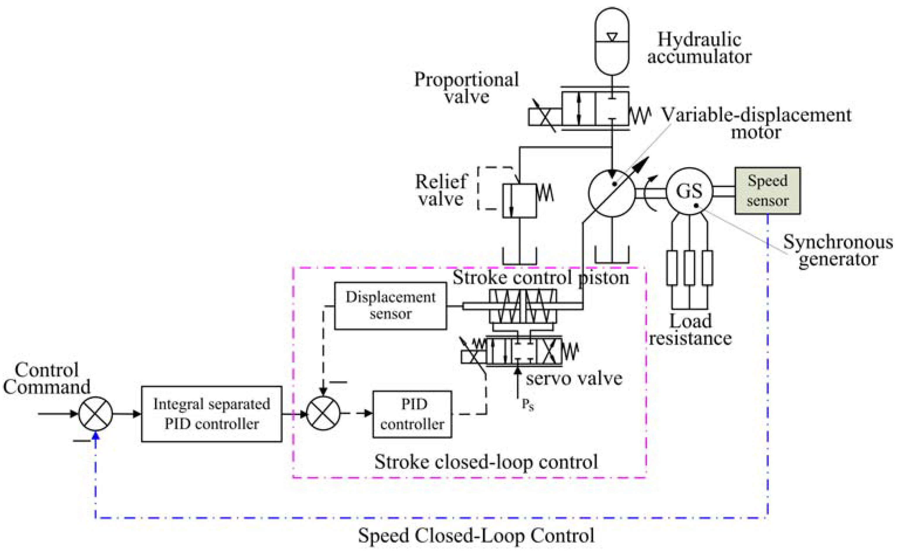
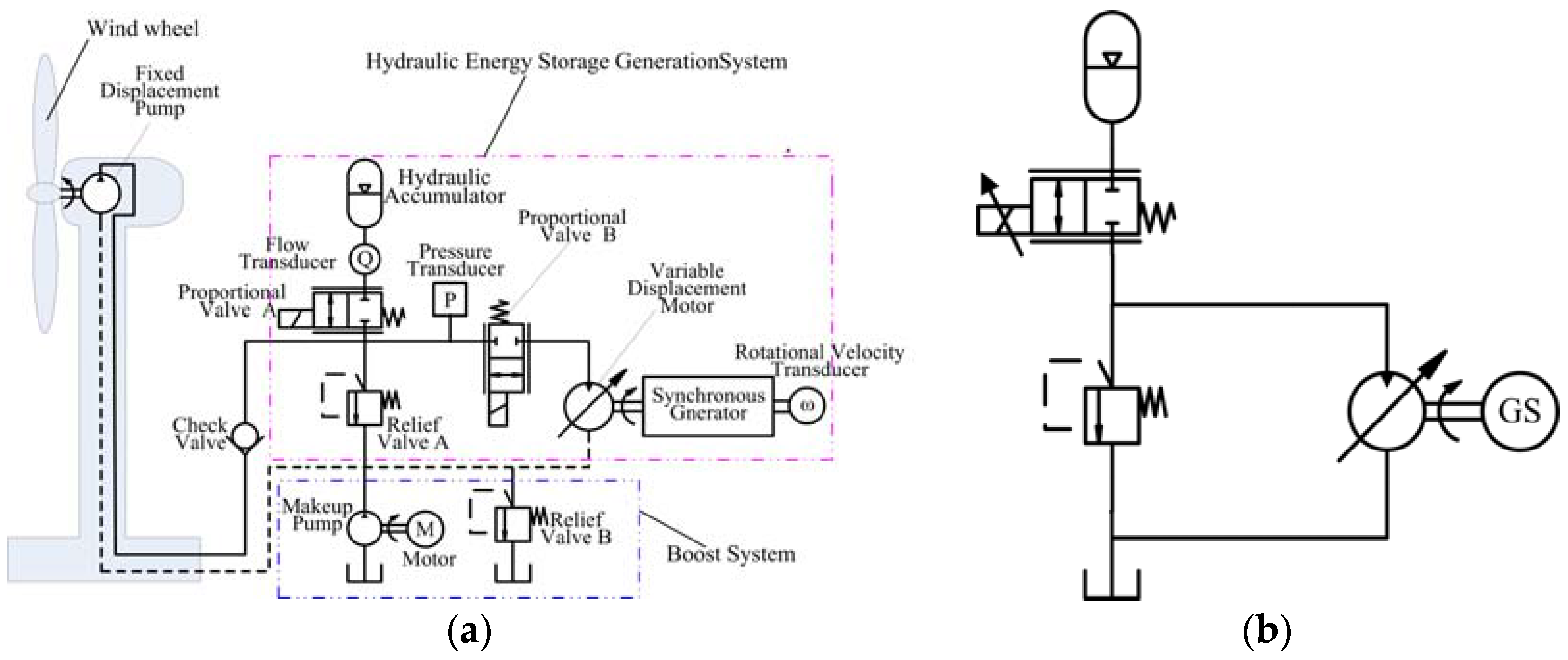
2.1. System Overview

The schematic diagram of the HESGS is shown in Figure 1b. The HESGS is comprised of a hydraulic accumulator, proportional control valve, relief valve, variable displacement motor and synchronous generator. The generator is connected with the variable motor through a shaft coupling. The role of the proportional valve in this system is an on-off switch of the accumulator oil flow. The relief valve controls the maximum operating pressure and protects the system against overpressure. The variable motor is a key component of the HESGS, which converts hydraulic energy into mechanical energy absorbed by the synchronous generator. The motor speed is kept at the synchronous speed of the synchronous generator relying on the constant speed control system of the HESGS, which makes the real-time regulating of the motor displacement. The performance of the constant speed control system can be easily impacted by internal and external interference. The load power change, regard as a significant external disturbance to the motor speed control system, will cause a severe fluctuation of the motor speed and the instable generating frequency. Hence it is very important whether or not the constant speed control of the HESGS is robust to varied load power.

2.2. Control Scheme

The constant speed control scheme of the HESGS considered in this research is shown in Figure 2. The control system aims at the constant rotational speed of the motor, regardless of whether the pressure in the accumulator or load power changes. From Figure 2, it appears that a double closed-loop control is adopted. One is the swashplate angle closed-loop control of the variable motor, which is virtually a stroke control servo system of valve-controlled cylinder. The stroke closed-loop control system consists of servo valve, stroke control piston and displacement sensor. The movement process of the stroke control piston is regulated by the output flow rate and pressure of the servo valve, which is in proportion to the input signal to the servo valve. The position of the stroke control piston is detected and converted into electrical signals by the displacement sensor, which is compared with the angle reference signal of the stroke closed-loop control. The comparison result is called the position deviation, which is equal to zero when the stroke control piston arrives at the desired position. If the deviation is not zero, the motion of the stroke control piston is controlled by the servo valve towards lower deviation. Thus, the swashplate angle and the angle reference signal always are matched. A PID controller is used to improve the fast response of the displacement adjustment and ensure the positioning precision.
The other one is the speed closed-loop control of the motor. A speed sensor plays a major role in the speed control of the motor, and its accuracy has a significant impact on the steady-state precision of the speed control system. The speed deviation, which is calculated by subtracting the actual speed measured by the speed sensor from the speed reference signal, is converted into the angle reference signal by using the integral separated PID controlled algorithm. The motor speed will decrease under the condition of a reduction in the accumulator pressure or an increase in the load power. The speed deviation will become positive and the angle reference signal will increase, which will cause an increase in the displacement of the motor. The motor will accelerate because the hydraulic torque generated by the motor is greater than the load torque caused by the generator. The speed deviation is zero when the motor speed rises to the speed reference signal, meanwhile, the angle reference signal and the displacement of the motor have no change. In this way, the motor speed is maintained at the desired speed. The motor speed will increase on the condition of an increase in the accumulator pressure or a decrease of the load power. The changing trend of the control variables is just opposite. The integral separated PID controller is applied to avoid serious speed overshoot when the motor starts.

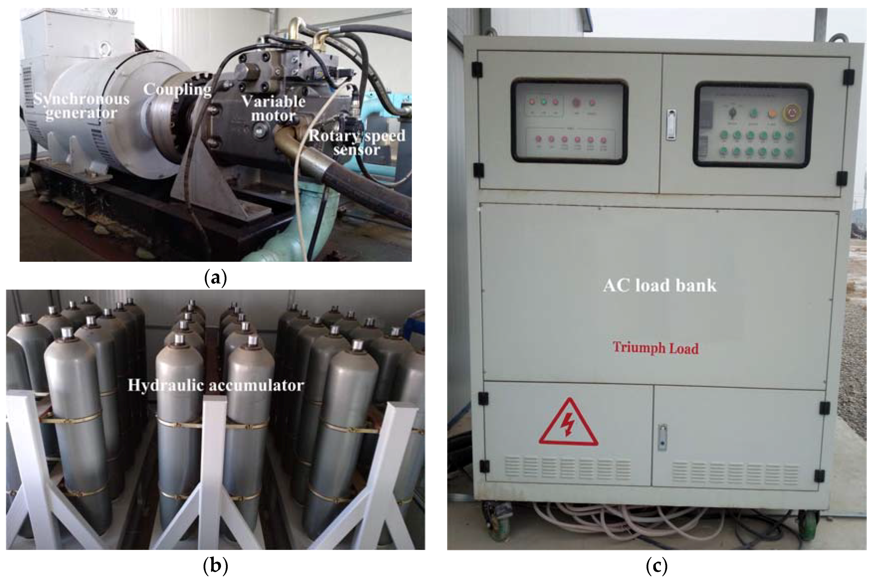
2.3. Experimental Test Rig

The experimental test rig of the HESGS is set up, as shown in Figure 3. A Rexroth A4V motor is adopted to transform hydraulic power stored in the hydraulic accumulator into mechanical power. The rotary speed sensor is integrated in the variable motor. Brushless excitation synchronous generator is connected with the variable motor via a flexible coupling, which converts mechanical energy from the motor into electrical energy. The electrical energy produced by the synchronous generator is fed into the load bank. It is transformed into heat in the load bank and dissipated in the air. Thirty 200L bladder accumulators (Chaori company, Fenhua, China) are chosen as the hydraulic energy storage device because they have a good economy and dynamics performance. Before the experiment, the oil in tank is pumped into the hydraulic accumulator by means of the boost system.

3. Mathematical Model

Before building the mathematical model of the whole system, the following assumptions are considered:
(1)
The pressure loss in the pipeline and the dynamic characteristic of the pipeline are neglected for short pipeline length.
(2)
Internal and external leakages of the variable motor are laminar flow, which are proportional to the differential pressure. The pressure of the variable motor housing is zero.
(3)
Bulk modulus and density of the hydraulic oil are constant.
(4)
The dynamic of the relief valve is considered negligible.

3.1. Hydraulic Accumulator

The bladder accumulator is used in the HESGS for storing the oil from the pump, which comprises a steel shell, a rubber bladder and anti-extrusion system. The rubber bladder is filled with nitrogen gas. The working process of nitrogen gas obeys the ideal gas law:
P a V a n = P 0 V 0 n
P a = P 0 V 0 n V a n = P 0 V 0 n ( V 0 + Q a dt ) n
Q a = V 0 P 0 1 n n P a n + 1 n d P a d t
where P0 and V0 are the gas pre-charge pressure and the accumulator volume. Pa and Va represent the pressure and volume of gas in the process of compression. Qa is the accumulator charge or discharge flow. n is the polytropic index, which is 1 for an isothermal process and 1.4 for an adiabatic process.

3.2. Proportional Valve

The proportional valve has been widely used in hydraulic system for the perfect control characteristic. The output flow of proportional valve is proportional to the input current signal. The corresponding equations are as follows:
Q p v = C d A 2 ( P p v i n P p v o u t ) ρ
A = { A max I p v 0 I p v 1 A max I p v > 1
where Qpv is the flow through the proportional valve. Ppvin and Ppvout represent the inlet and outlet pressure of the proportional valve. Cd is the flow coefficient. Amax is the maximum opening area. A is the actual opening area and is proportional to the input current Ipv. The proportional valve is set to control the charge and discharge flow of the accumulator. The accumulator is closed when the input current Ipv is zero.

3.3. Relief Valve

The relief valve plays an important role in securing the hydraulic system. Its functions can mainly be divided into two types: (1) adjusting and limiting the maximum system pressure; (2) keeping the system pressure constant:
Q r v = { ( P r v i n P r v o u t P o p )   K r v P r v i n P r v o u t P o p 0 P r v i n P r v o u t < P o p
where Prvin and Prvout are the inlet pressure and outlet pressure of the relief valve, respectively. Qrv represents the overflow flow through a relief valve, which is computed by Equation (6). Pop is the cracking pressure and Krv is the pressure-flow coefficient. When the difference between Prvin and Prvout is greater than Pop, the valve core in the relief valve moves away from the valve seat, the oil overflows into the tank through the orifice formed by the valve core and valve seat.

3.4. Variable Motor

The stroke closed-loop control system of the variable motor is a small and typical electro-hydraulic position servo system of a valve-controlled cylinder, so a first-order model can be used to describe the dynamic characteristics of the variable mechanism [20,21]:
D m ( s ) U m ( s ) = K m T m s + 1
where Dm is the displacement of the variable motor. Um is the control signal to the servo controller. Km is the motor stroke-control gain and Tm is the time constant of the stroke-control.
According to the continuity equation, the flow equation for the pipeline can be written as:
Q a Q r v Q m = V β d P 1 d t
where Qm is the motor flow. V is the total volume under compression, including the oil in the high-pressure pipeline, the accumulator and the variable motor. β is the effective bulk modulus of hydraulic oil. P1 and P2 represent the inlet pressure and outlet pressure of the motor:
Q m = D m ω m + C i m ( P 1 P 2 ) + C e m P 1
where ωm is the rotational speed of the motor. Cim and Cem represent the internal and the external leakage coefficients of the motor respectively. The dynamic equation of the load inertia for the motion is established as follows using Newton’s second law:
D m ( P 1 P 2 ) = J t d ω m d t + B v ω m + T f + T d
where Jt is the total inertia of the rotor in the variable motor and the generator. Bv is the coefficient of viscous friction of the rotor. Tf is the Coulomb friction torque and Td is the external torque for electric power generation. Td is the disturbance to the entire system because it varies with load power.

3.5. Synchronous Generator

The synchronous generator model is obtained based on Park transformation [22]. Voltage balance equations of the rotor and stator in dq0 coordinates are derived according to the generalized Ohm’s law:
U s d = d ψ s d d t ω e ψ s q R a i s d
U s q = d ψ s q d t + ω e ψ s d R a i s q
0 = d ψ d d d t + R d d i d d
0 = d ψ d q d t + R d q i d q
where Usd and Usq are the stator voltage on the Park’s d axis and Park’s q axis. ψsd and ψsq are the flux linkage of the stator windings. isd and isq are the stator current on the Park’s d axis and Park’s q axis and Ra is the stator winding resistance. ψdd and ψdq are the flux linkage of the damper windings. idd and idq are the stator current through the damper windings. Rdd and Rdq are the damper winding’s resistance.
The expression of the winding flux linkage equation is established below. The electromagnetic torque Γ is given by Equation (20):
ψ s d = L s d i s d + 3 2 M s f i f l + 3 2 M s d i d d
ψ s q = L s q i s q + 3 2 M s q i d q
ψ f l = L f i f l + 3 2 M s f i s d + M f d i d d
ψ d d = L d d i d d + 3 2 M s d i s d + M f d i f l
ψ d q = L d q i d q + 3 2 M s q i s q
Γ = p ( ψ s d i s q ψ s q i s d )
where Msf, Msd, Msq and Mfd are the mutual inductance between the two windings. Lsd, Lsq, Lf, Ldd and Ldq are the inductance of the windings. p is the number of pole pairs.

3.6. Speed Sensor

A rotational speed sensor plays an important role in the speed control, which converts the motor speed into the electrical signal:
U s s = ω m K s s
where Uss is the corresponding voltage value. Kss is the gain coefficient of the rotational speed sensor.

3.7. Load Bank

The load bank is essentially a variable electrical resistance. The relationship among the voltage Ul, the resistance Rl and the current Il is as follows:
I l = U l R l

4. Simulation and Experiment Study

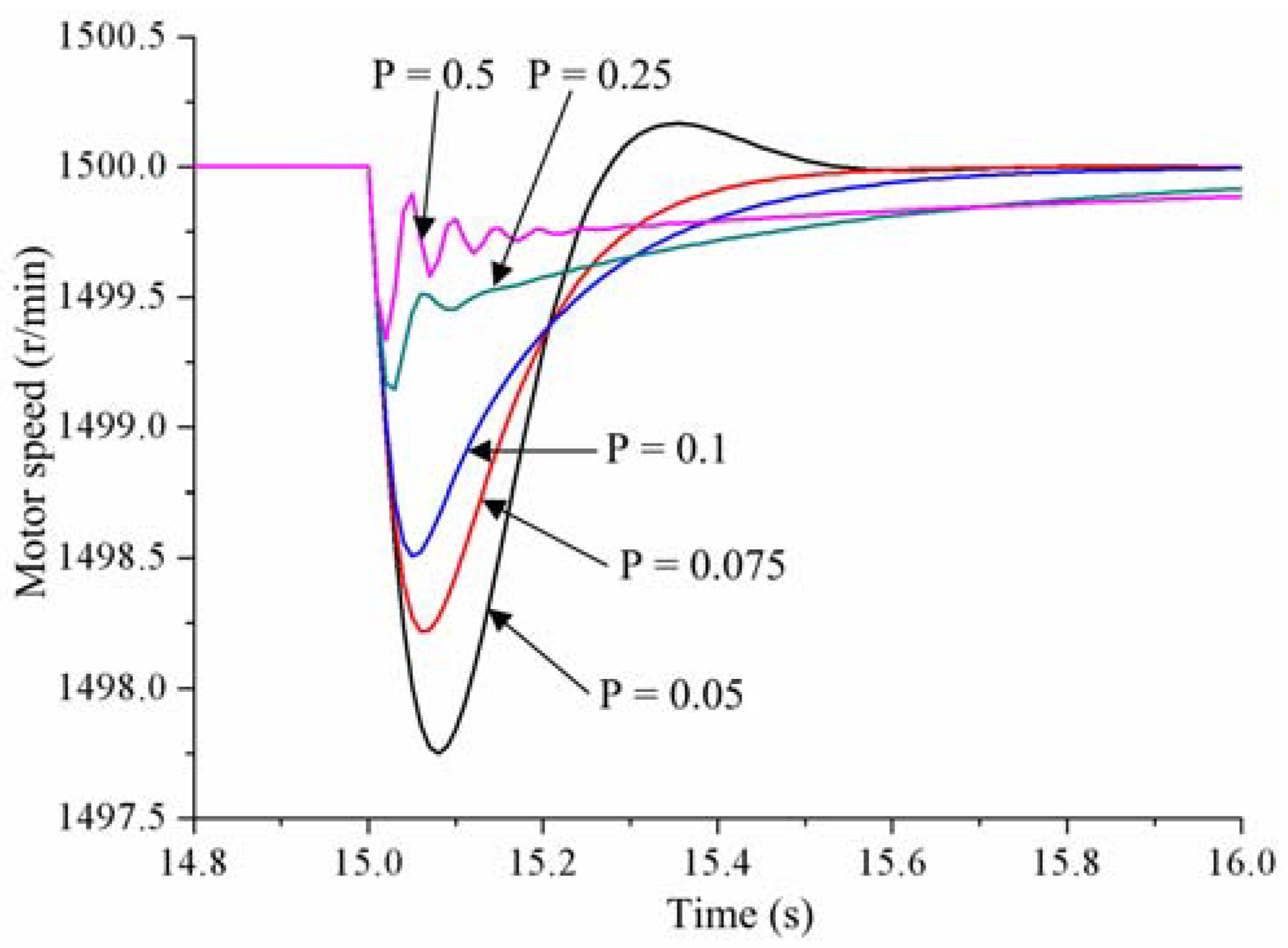
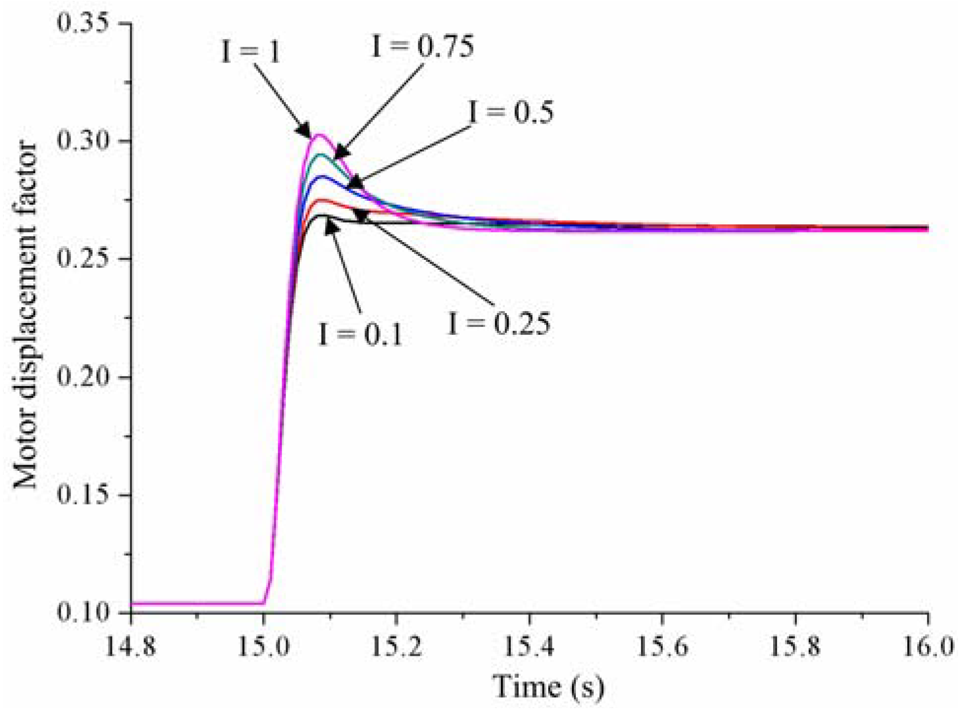
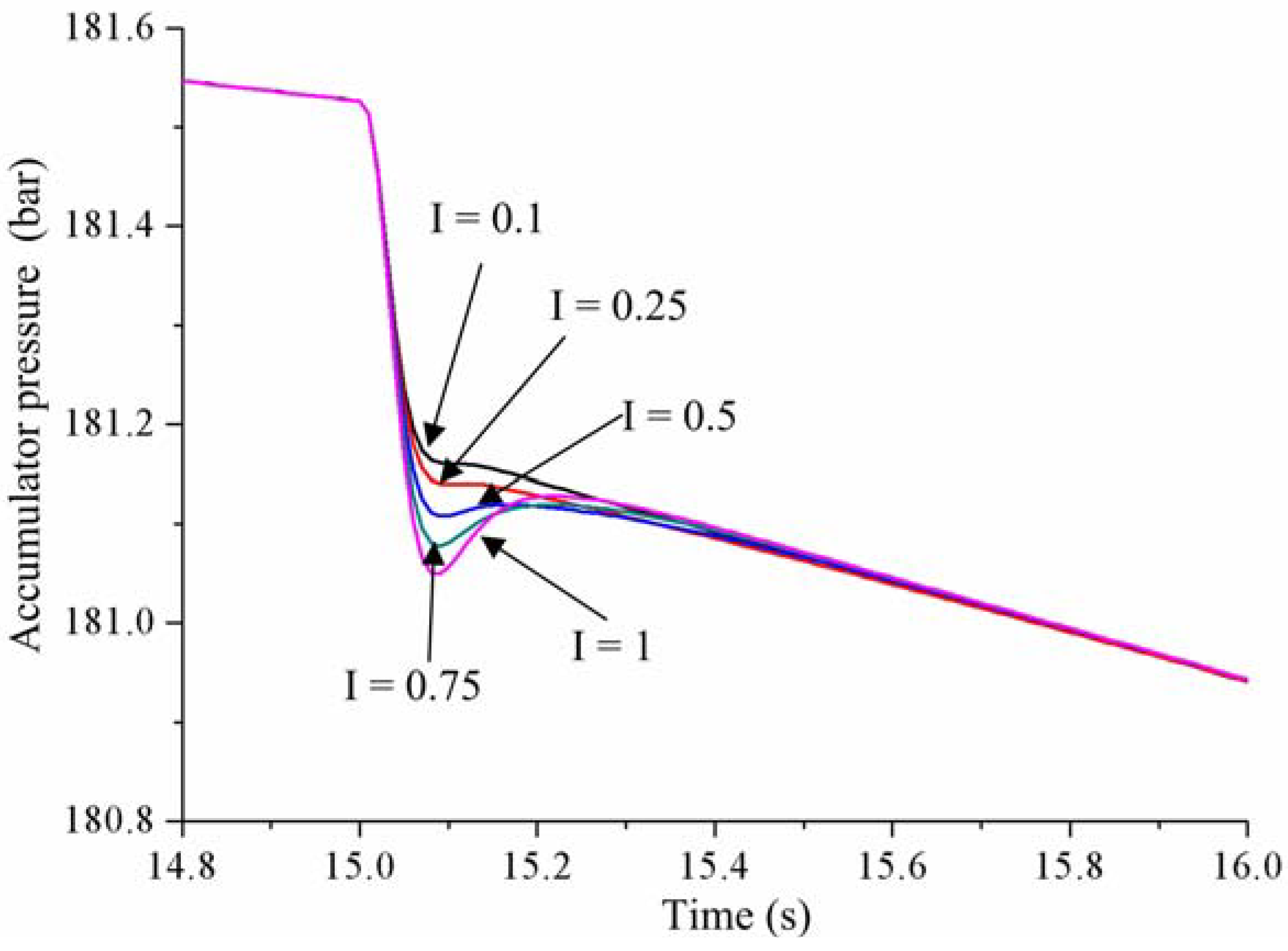
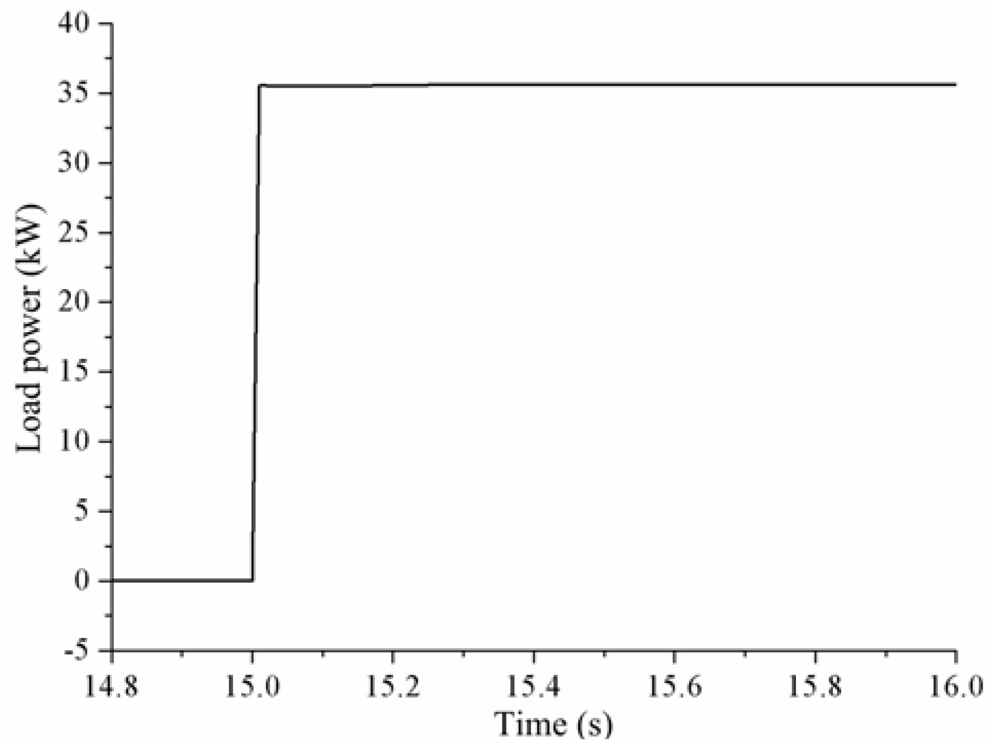
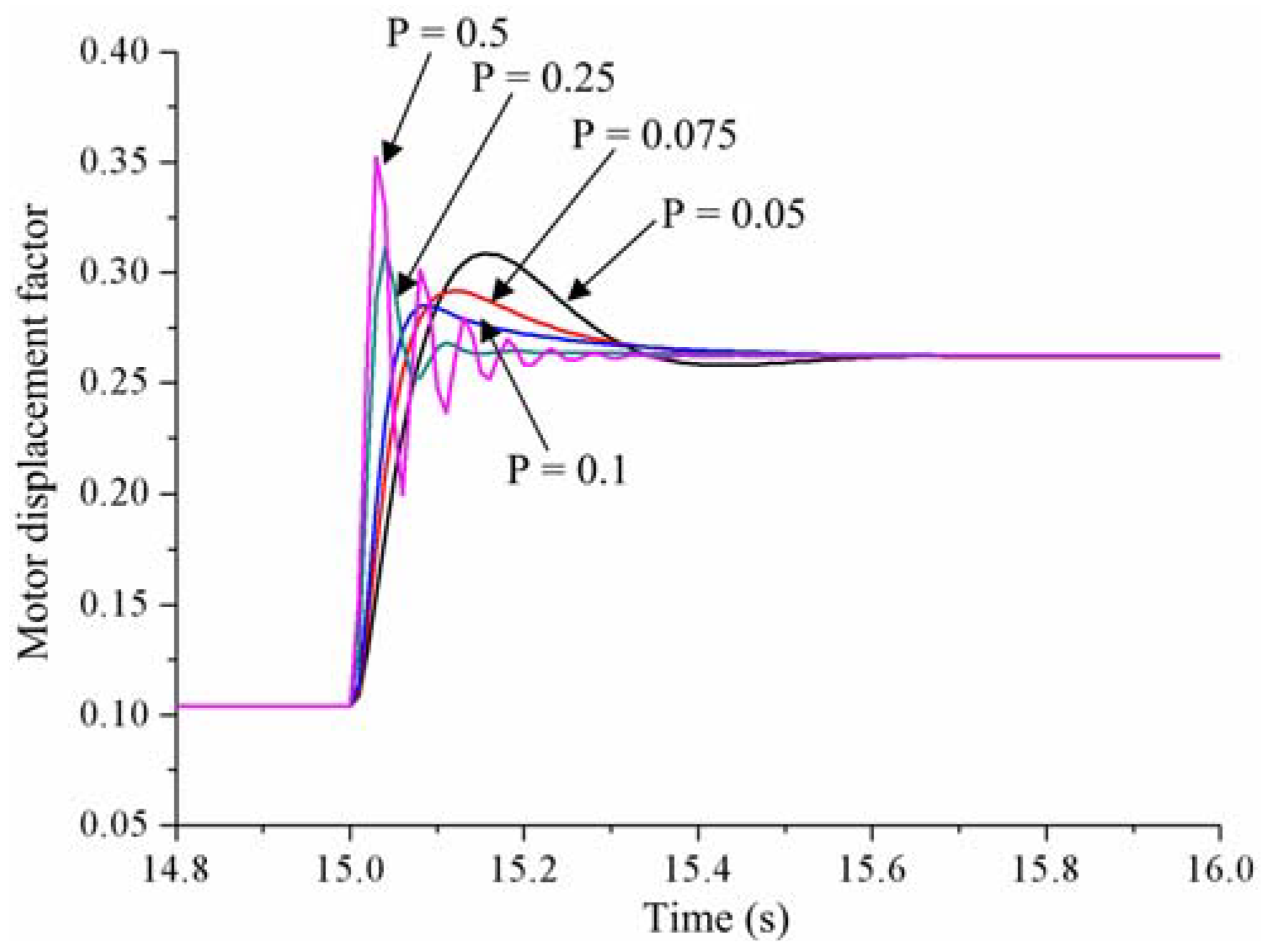
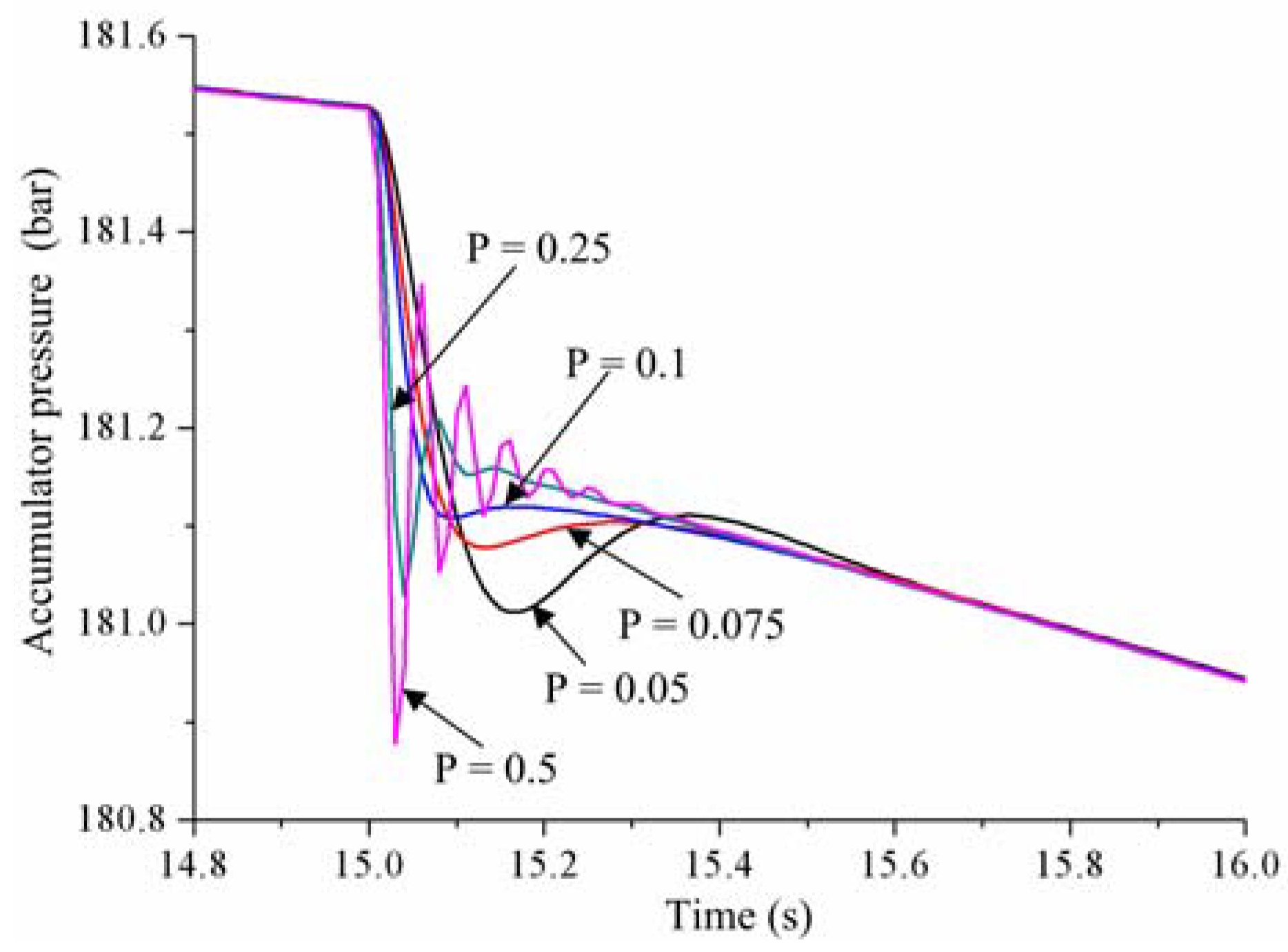
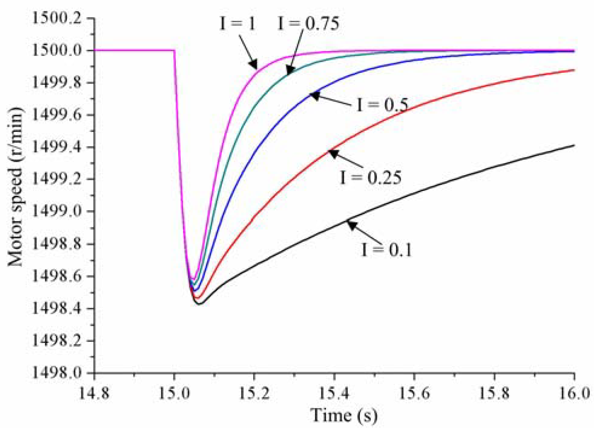
4.1. Simulations of the Robustness on Constant Load Power Step

The simulation model of the HESGS is constructed under the MATLAB/SIMULINK environment (version 6.5, MathWorks Company, Natick, MA, USA). The simulation studies are carried out to validate the effectiveness of the constant speed control and evaluate the influence of the proportional gain and integral gain of the integral separated PID controller on the robustness of the proposed control scheme. The main parameters of the simulation model are shown in Table 1.
In this section, a step change in the load power (from 0 kW to 35 kW) is used as an external torque disturbance to the HESGS, as shown in Figure 4. The load power mutation occurs at 15 s. The responses to load power step subsequently are shown, which will give the torque disturbance rejection performance of the constant motor speed control when the load power suddenly increases.
Figure 5 shows that the smaller the proportional gain is, the slower the motor displacement change is. From Figure 5 and Figure 6, it is shown that the maximum speed deviation of the motor will decrease with the increase of the proportional gain. The speed deviation is 2.25 rpm when the proportional gain is 0.05. It is the slowest in the change of the motor displacement. Meanwhile, the motor speed overshoots the speed command 1500 rpm on account of the slow adjusting of the motor displacement. When the proportional gain is equal to 0.5, the minimum speed deviation is nearly 0.75 rpm. However oscillation occurs at the motor displacement. The motor speed oscillates as a result of fluctuating motor displacement.
The accumulator pressure responses are shown in Figure 7, which illustrates that the accumulator pressure decreases rapidly owing to the increase of the load power. It has been shown that the shapes of the motor displacement and the accumulator pressure are the same, but they vary in the opposite direction.
The motor displacement responses with different integral gains are displayed in Figure 8. It can be seen that the motor displacement changes simultaneously regardless of the integral gain, which causes that the maximum speed deviations are almost the same, as shown in Figure 9.
The motor displacement overshooting increases when the integral gain becomes larger. The overall recovery time of the motor speed is the shortest because of the largest motor displacement overshooting. From Figure 10, it has been shown that the variation trend of the accumulator pressure is almost identical to that of the motor displacement; the change direction of the accumulator pressure is the reverse of the movement direction of the motor displacement.

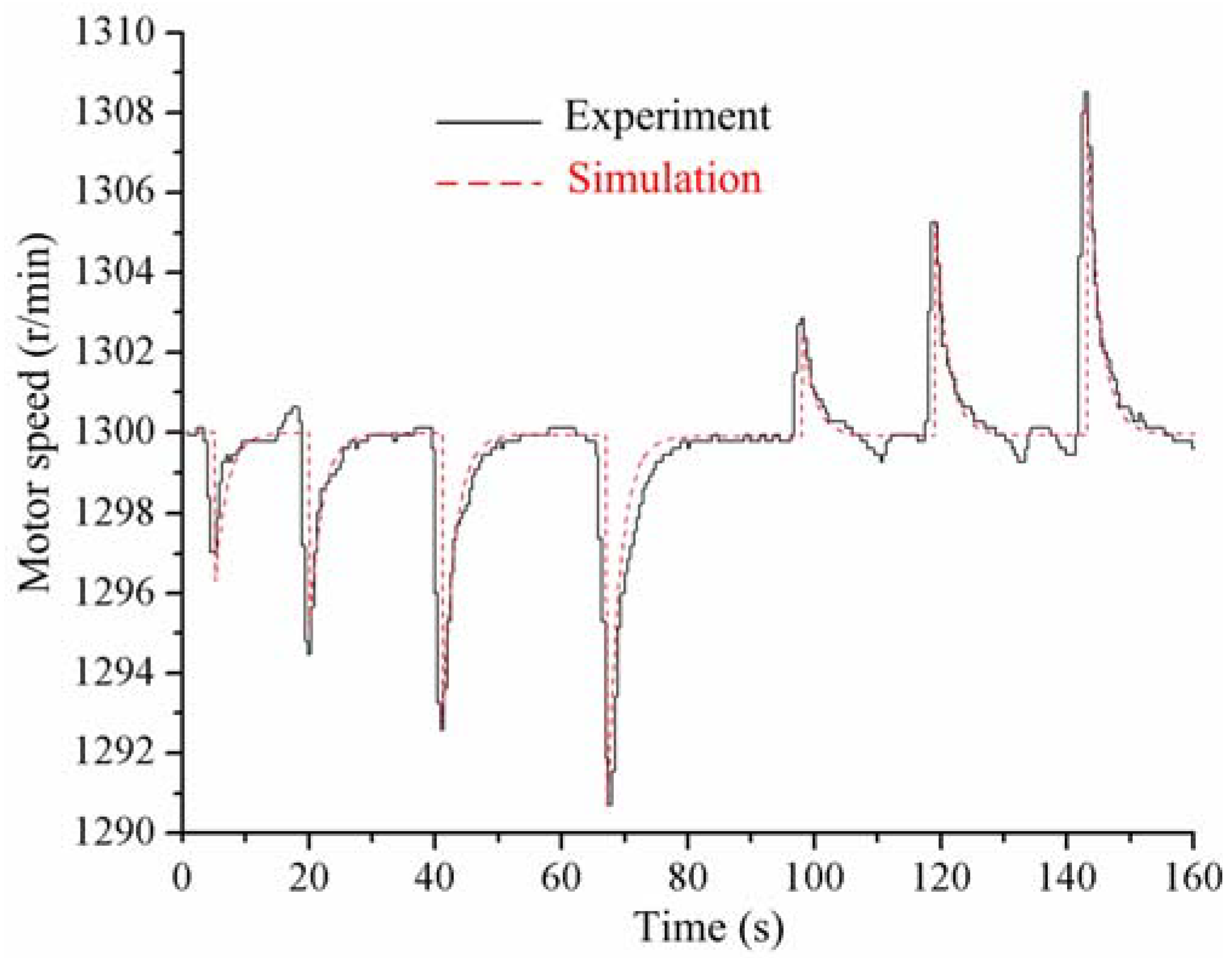
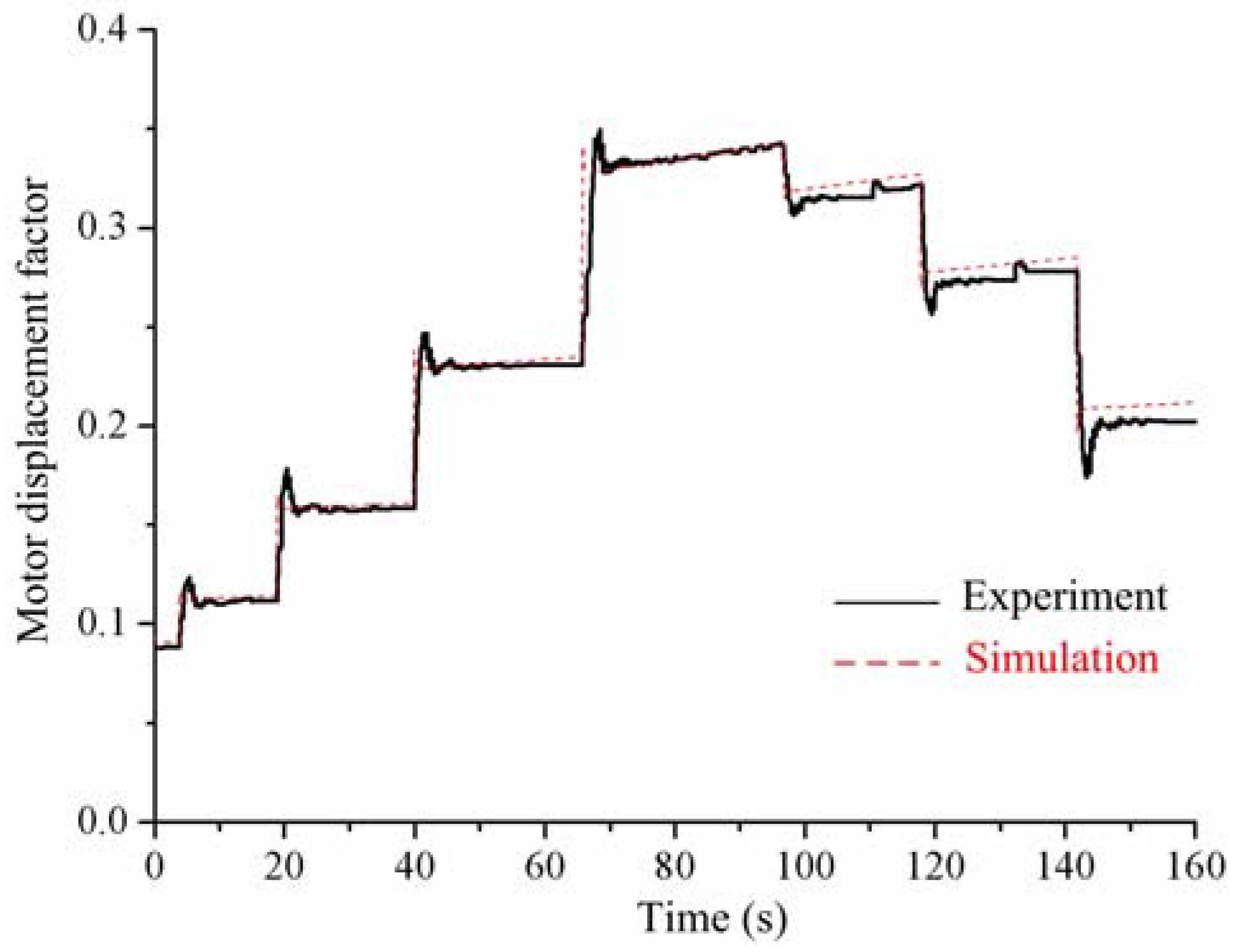
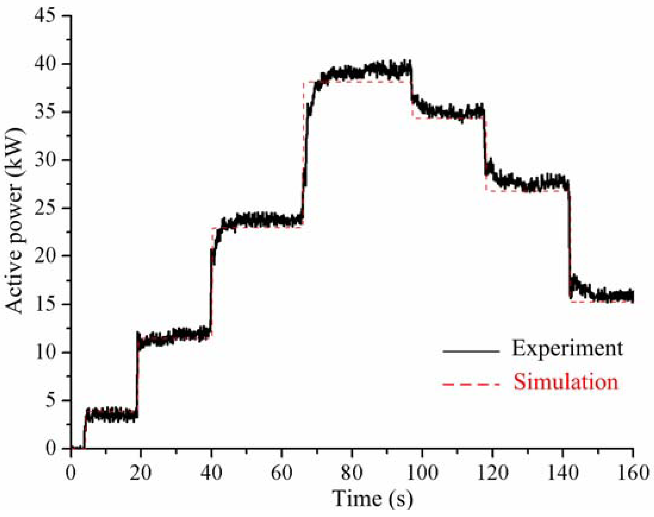
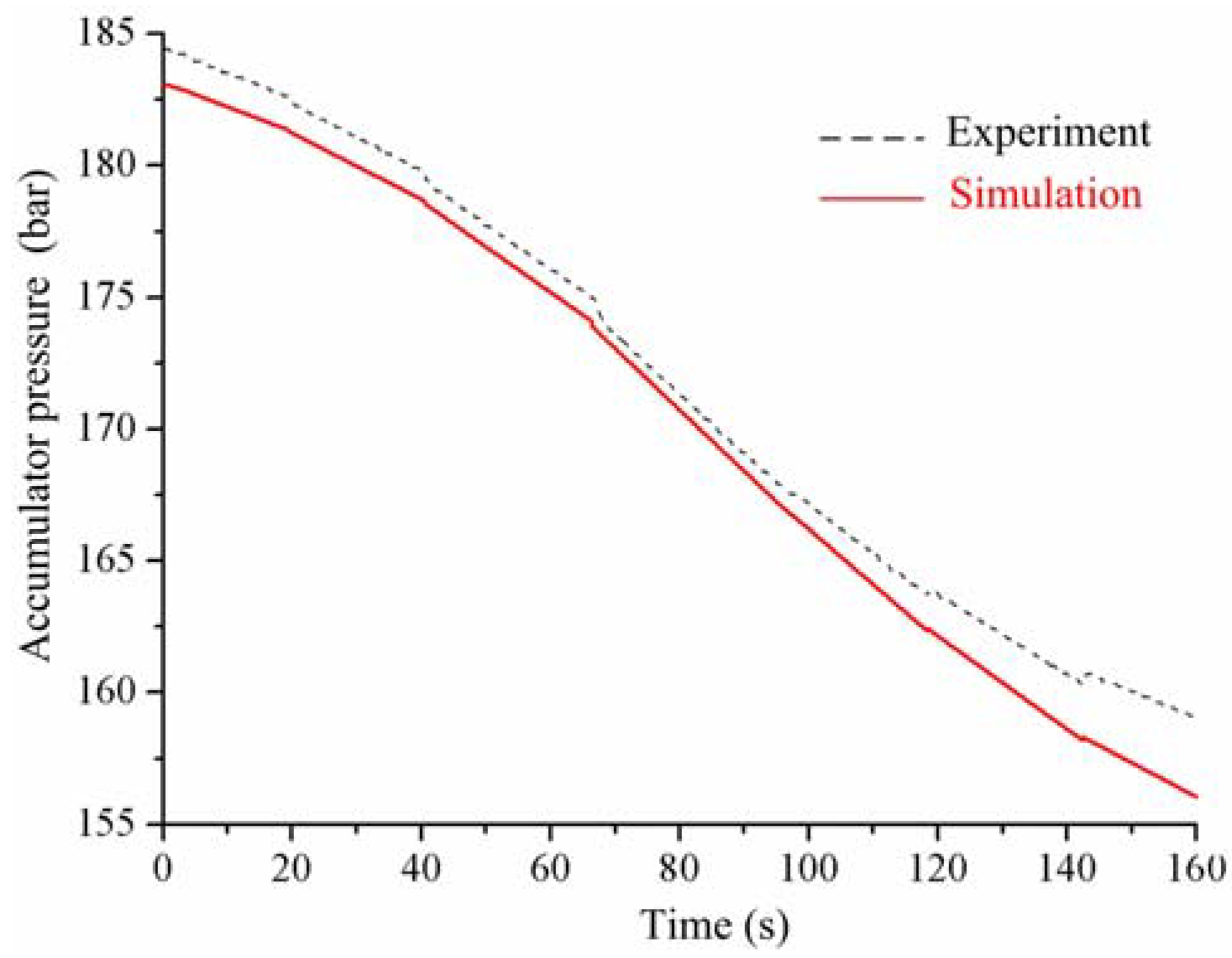
4.2. Experiments of the Robustness on Varied Load Power Step

In the course of the work of a hydraulic wind turbine with hydraulic accumulator, wind energy captured by wind turbine under turbulence inflow is entirely stored in the hydraulic accumulator of the HESGS. The HESGS produces electrical energy by converting the hydraulic energy stored in the hydraulic accumulator. The wind energy storage process and the power generation process of the HESGS are independent processes. Accordingly, the power generation process of the HESGS is not affected by the stochastic nature of the wind turbulence and it is mainly influenced by the load power variability because of the frequent change of electric power consumption. The experiments are achieved not only to verify the simulation results discussed in the Section 4.1, but also to study the robustness of the constant motor speed control on varied load power disturbance.
The motor speed command in these experiments is set to 1300 in order to ensure the experiment safety. The proportional gain and integral gain have the same value 0.1. The load power is easily changed by varying the control signal of the load bank. The variations of load power step are 8 kW, 10 kW and 15 kW. The load power rises in the first half of the experiment and decreases in the latter part. Simulation and experiment results of the active power output by the synchronous generator are shown in Figure 11.
Figure 12 shows the simulation and experiment results of the motor speed when a load power disturbance is present. It is easy to conclude that the speed deviation becomes greater as the load power disturbance increases. The experimental results also show that the actual steady-state speed of the motor is close to the desired speed and has a small change around 1300 rpm, which conforms to the requirements of the generating frequency. In Figure 13, it is shown that the change in the motor displacement increases in proportion with the change in the load power. The pressure curve of the accumulator under varied load power step is demonstrated in the Figure 14. A corresponding change in the pressure of the hydraulic accumulator is produced due to the load power disturbance. As can be seen from Figure 11, Figure 12, Figure 13 and Figure 14, the simulation results are almost identical to the experiment results. Some ripple of the experiment results may be the result of the dead zone of the integral separated PID controller.

5. Conclusions

Aiming to eliminate the fluctuation and intermittence of wind power, the hydraulic accumulator is used to store wind energy captured by a wind turbine. With light wind or no wind, electric energy is produced by the synchronous generator via the HESGS. The HESGS works on the strong external torque disturbance for the variety of load power and therefore it is essential to study the robustness of the constant speed control system to load power disturbance.
This paper deduces the mathematical expression of all the components and constructs the whole system model based on MATLAB. A double closed-loop control scheme is employed to meet the need for a constant motor speed regardless of the change of load power. The influences of the proportional gain and integral gain to the robustness of the constant speed control system under constant load power step are simulated. To test the simulation model and discuss the robustness under the condition of variable load power, the comparative investigations of the simulation and experiment are implemented under the same conditions. Under the condition of constant 35 kW load power step, the speed deviation diminishes from 2.25 to 0.75 rpm, as the proportional gain range is between 0.05 and 0.5. Similarly, the recovery time of the motor speed will decrease as the integral gain raises. When the integral gain is equal to one, the recovery time reaches its minimum 0.4 s. The results show the proposed control approach has good performance and strong robustness, which can get rapidly back to the original speed and realizes zero steady-state error for load power step. It should be emphasized that load power step cannot be too high. There is a big swing of the motor speed on account of large load power variety, which can give rise to the generating frequency instability.

Author Contributions

G.Y. and L.W. conceived the research; Z.L. completed the simulation model and control system design; Z.L. and D.Y. performed model verification and wrote the paper; Y.T. and Z.L. performed the collection and analysis of the experimental data; G.Y. critically revised the paper and provided constructive suggestions.

Acknowledgments

This work was financially supported by the National Natural Science Fund Project of China (51765033) and the Science and Technology Major Project of Gansu province (17ZD2GA010).

Conflicts of Interest

The authors declared no potential conflicts of interest with respect to the research, authorship, and publication of this article.

References

  1. Jha, D. A comprehensive review on wind energy systems for electric power generation: Current situation and improved technologies to realize future development. Int. J. Renew. Energy Res. 2017, 7, 1786–1805. [Google Scholar]
  2. Global Wind Energy Council (GWEC). Global Wind Report: Annual Market Update; GWEC: Brussels, Belgium, 2016. [Google Scholar]
  3. Silva, P.; Giuffrida, A.; Fergnani, N.; Macchi, E.; Cantù, M.; Suffredini, R.; Schiavetti, M.; Gigliucci, G. Performance prediction of a multi-MW wind turbine adopting an advanced hydrostatic transmission. Energy 2014, 64, 450–461. [Google Scholar] [CrossRef]
  4. Ragheb, A.; Ragheb, M. Wind turbine gearbox technologies. In Proceedings of the 2010 1st International Nuclear Renewable Energy Conference (INREC), Amman, Jordan, 21–24 March 2010. [Google Scholar]
  5. Saidur, R.; Rahim, N.A.; Islam, M.R.; Solangi, K.H. Environmental impact of wind energy. Renew. Sustain. Energy Rev. 2011, 15, 2423–2430. [Google Scholar] [CrossRef]
  6. Pedersen, E.; Larsman, P. The impact of visual factors on noise annoyance among people living in the vicinity of wind turbines. J. Environ. Psychol. 2008, 28, 379–389. [Google Scholar] [CrossRef]
  7. Polinder, H.; van de Pijl, F.F.A.; de Vilder, G.J.; Tavner, P.J. Comparison of direct-drive and geared generator concepts for wind turbines. IEEE Trans. Energy Convers. 2006, 21, 725–733. [Google Scholar] [CrossRef]
  8. Cai, M.; Wang, Y.; Jiao, Z.; Shi, Y. Review of fluid and control technology of hydraulic wind turbines. Front. Mech. Eng. 2017, 12, 312–320. [Google Scholar] [CrossRef]
  9. Nikranjbar, A.; Sharbabaki, A.N. Simulation and control of wind turbine using hydrostatic drive train. Majlesi J. Energy Manag. 2013, 2, 12–17. [Google Scholar]
  10. Jiang, Z.; Yang, L.; Gao, Z.; Moan, T. Numerical simulation of a wind turbine with a hydraulic transmission system. Energy Procedia 2014, 53, 44–55. [Google Scholar] [CrossRef]
  11. Zhang, Y.; Kong, X.; Li, H.; Chao, A. Controls of hydraulic wind turbine. In Proceedings of the 2015 International Conference on Mechanical Engineering and Electrical Systems, EDP Sciences, Singapore, 16–18 December 2015. [Google Scholar]
  12. Díaz-González, F.; Sumper, A.; Gomis-Bellmunt, O.; Villafáfila-Robles, R. A review of energy storage technologies for wind power applications. Renew. Sustain. Energy Rev. 2012, 16, 2154–2171. [Google Scholar] [CrossRef]
  13. Chudy, M.; Herbst, L.; Lalk, J. Wind farms associated with flywheel energy storage plants. In Proceedings of the Innovative Smart Grid Technologies Conference Europe (ISGT-Europe), Istanbul, Turkey, 12–15 October 2014. [Google Scholar]
  14. Ali, A.E.; Libardi, N.C.; Anwar, S.; Izadian, A. Design of a compressed air energy storage system for hydrostatic wind turbines. Energy 2018, 6, 229–244. [Google Scholar] [CrossRef]
  15. Liu, C.; Cheng, M.-S.; Zhao, B.-C.; Dai, Z.-M. A wind power plant with thermal energy storage for improving the utilization of wind energy. Energies 2017, 10, 2126. [Google Scholar] [CrossRef]
  16. Yao, D.L.; Choi, S.S.; Tseng, K.J.; Lie, T.T. A statistical approach to the design of a dispatchable wind power-battery energy storage system. IEEE Trans. Energy Convers. 2009, 24, 916–925. [Google Scholar] [CrossRef]
  17. Liu, Z.; Yang, G.; Wei, L.; Yue, D. Variable speed and constant frequency control of hydraulic wind turbine with energy storage system. Adv. Mech. Eng. 2017, 9, 1–10. [Google Scholar] [CrossRef]
  18. Qin, C.; Innes-Wimsatt, E.; Loth, E. Hydraulic-electric hybrid wind turbines: Tower mass saving and energy storage capacity. Renew. Energy 2016, 99, 69–79. [Google Scholar] [CrossRef]
  19. Yu, H.; Liu, Y.; Wang, Y.; Wang, M.; Qin, X. Speed governing controller of gasoline engine based on integral-separation fuzzy PID control. In Proceedings of the 2016 3rd International Conference on Information Science and Control Engineering (ICISCE), Beijing, China, 8–10 July 2016. [Google Scholar]
  20. Jen, Y.; Lee, C. Robust speed control of a pump-controlled motor system. IEE Proc. D Control Theory Appl. 1992, 139, 503–510. [Google Scholar] [CrossRef]
  21. Xu, M.; Ni, J.; Chen, G. Dynamic simulation of variable-speed valve-controlled-motor drive system with a power-assisted device. J. Mech. Eng. 2014, 60, 581–591. [Google Scholar] [CrossRef]
  22. Hernandez, R.G.; Ramirez, R.G. Modeling and control of a wind turbine synchronous generator. In Proceedings of the Electronics, Robotics and Automotive Mechanics Conference(CERMA), Cuernavaca, Morelos, Mexico, 15–18 November 2011. [Google Scholar]
Figure 1. Principle of the novel hydraulic wind turbine and hydraulic energy storage generation system (HESGS). (a) Hydraulic wind turbine with hydraulic energy storage system; (b) Hydraulic energy storage generation system.
Energies 11 01310 g001
Figure 2. Constant speed control system of the hydraulic energy storage generation system.
Energies 11 01310 g002
Figure 3. Photograph of the HESGS test rig. (a) Variable motor and generator; (b) Hydraulic accumulator; (c) Load bank.
Energies 11 01310 g003
Figure 4. Load power step of the HESGS.
Energies 11 01310 g004
Figure 5. Simulated motor displacement responses of the HESGS with different proportional gains.
Energies 11 01310 g005
Figure 6. Simulated motor speed responses of the HESGS with different proportional gains.
Energies 11 01310 g006
Figure 7. Simulated accumulator pressure responses of the HESGS with different proportional gains.
Energies 11 01310 g007
Figure 8. Simulated motor displacement responses of the HESGS with different integral gains.
Energies 11 01310 g008
Figure 9. Simulated motor speed responses of the HESGS with different integral gains.
Energies 11 01310 g009
Figure 10. Simulated accumulator pressure responses of the HESGS with different integral gains.
Energies 11 01310 g010
Figure 11. Active power responses of the HESGS under varied load power step.
Energies 11 01310 g011
Figure 12. Motor speed responses of the HESGS under varied load power step.
Energies 11 01310 g012
Figure 13. Motor displacement responses of the HESGS under varied load power step.
Energies 11 01310 g013
Figure 14. Accumulator pressure responses of the HESGS under varied load power step.
Energies 11 01310 g014
Table 1. Main parameters in simulations.
ParameterSymbolValueUnit
Accumulator volumeV06000L
Gas precharge pressureP0100bar
Accumulator pressurePa185bar
Pipe diameterDp76mm
Pipe lengthLp2m
Motor displacementVm500cm3/rev
Moment of inertiaJt60kg·m2
Coefficient of viscosityBv0.05Nm/(r/min)
Number of pole pairsP2
Stator winding resistanceRa0.006Ω
Motor speed commandUs1500r/min

