1. Introduction
With the ratification of the Montreal Protocol in 1987 and the Kyoto Agreement in 1997, the search for sustainable substances for refrigeration applications has become urgent. Due to concerns about the unknown presumed unfavorable influence of various artificial refrigerants on the environment, the use of natural working fluids as refrigerants has been promoted [
1]. Among various natural refrigerants, carbon dioxide was considered to be the foremost choice thanks to its many excellent engineering application advantages [
2,
3]. However, the relatively large throttling loss, which decreases significantly the performance of the transcritical CO
2 refrigeration system, weakens considerably the competitive advantage of carbon dioxide, and recovering the power in the throttling process with the expander was hereby suggested by Lorentzen [
2].
After that, different expander-based transcritical CO
2 cycles were studied. Robinson et al. [
4] and Yang et al. [
5] analysed the performance of single-stage compression transcritical CO
2 cycles with a throttling valve and with an expander. Similar findings were that the irreversibility loss of the expansion process was reduced significantly almost by 35~50% with the appliance of the expander, and the COP of the throttling valve cycle was improved by on average 25~33%.Yang et al. [
6] presented that the COP of five investigated transcritical CO
2 cycles with expander were all higher than that of single-stage compression with throttle valve cycle, reaching from 30.81% to 45.62% at given design points, and the COP of two-stage compression with expander driving high-pressure stage (TCDH) cycle is the highest. Cho et al. [
7] developed a numerical simulation model to evaluate the performance of improved CO
2 cycles with an expander, an intercooler or a vapour injection. They concluded that three methods yielded a 28.3% (the expander efficiency of 30%), 13.1% and18.3% improvement of COP over that of the basic throttling valve cycle.
It is well known that the most efficient method to improve the performance of transcritical CO
2 cycle is to replace the throttling valve with an expander and recover its expansion work. Therefore, various types of CO
2 expanders were developed and investigated experimentally, such as free piston expander-compressor units [
8,
9], scroll expander [
10], rolling piston expander [
11,
12], vane rotary expander [
13,
14], reciprocating piston expander [
15,
16] and radial piston expander [
17]. After more than ten years of continuous development and improvement, the isentropic efficiency of expander was greatly improved, reaching a maximum of 77% [
12]. However, a successful application of expander in the market for transcritical CO
2 cycle products has not been reported.
In subcritical conditions, the CO
2 cycle works similarly as traditional Freon systems, as its high-side pressure and temperature are not independent in the two-phase region. So the experience in Freon systems can be used for reference. When the external temperature exceeds the CO
2 critical temperatures of 30.85 °C, the transcritical CO
2 cycle must be adopted to overcome this shortcoming. Unlike the subcritical vapour compression cycles, the high-side pressure and temperature of transcritical CO
2 cycle are independent and affected each other in operation, which increases the difficulty of operating condition control. The opening degree of throttling valve can be controlled accurately and rapidly, such as electronic expansion and electronic backpressure valves, which were suitable to regulate the operation of transcritical CO
2 plants and applied widely in the market. In the experiment of evaluating a model-free real-time optimization and control strategy proposed by Peñarrocha et al., two electronic expansion valves (controlled by a PI controller) carried on the precise real-time control to the high-side pressure according to the feedback signal of compression power [
18]. However, it is difficult for an expander. The driving force of expander only comes from the high and low pressure difference of transcritical CO
2 cycle. The interaction among many factors involved in the operation of expander, such as the pressure difference between high side and low side, the inlet temperature of expander, the consumption of expansion work, the mass flow rate, is bound to lead to weak regulation ability that restricts its popularization to the market.
Therefore, the quantification of working characteristics for transcritical CO
2 in different parameters is needed to find the appropriate control accuracy or method. Many researchers, such as Robinson [
4], Yang [
5,
6], Cho [
7], Cecchinato [
19], have studied the effects of parameters on COP for different transcritical CO
2 cycles including single- and two-stage cycles with or without an expander. However, only trends of COP variations with parameters are presented. It is necessary to understand the effect extent of parameters on the CO
2 cycle performance, which are essential on the operation control and design of the CO
2 systems. Therefore, in this paper, a quantitative analysis of the effect of parameters on COP is done by relative sensitivity in three typical expander-based transcritical CO
2 cycles.
3. Simulation Model
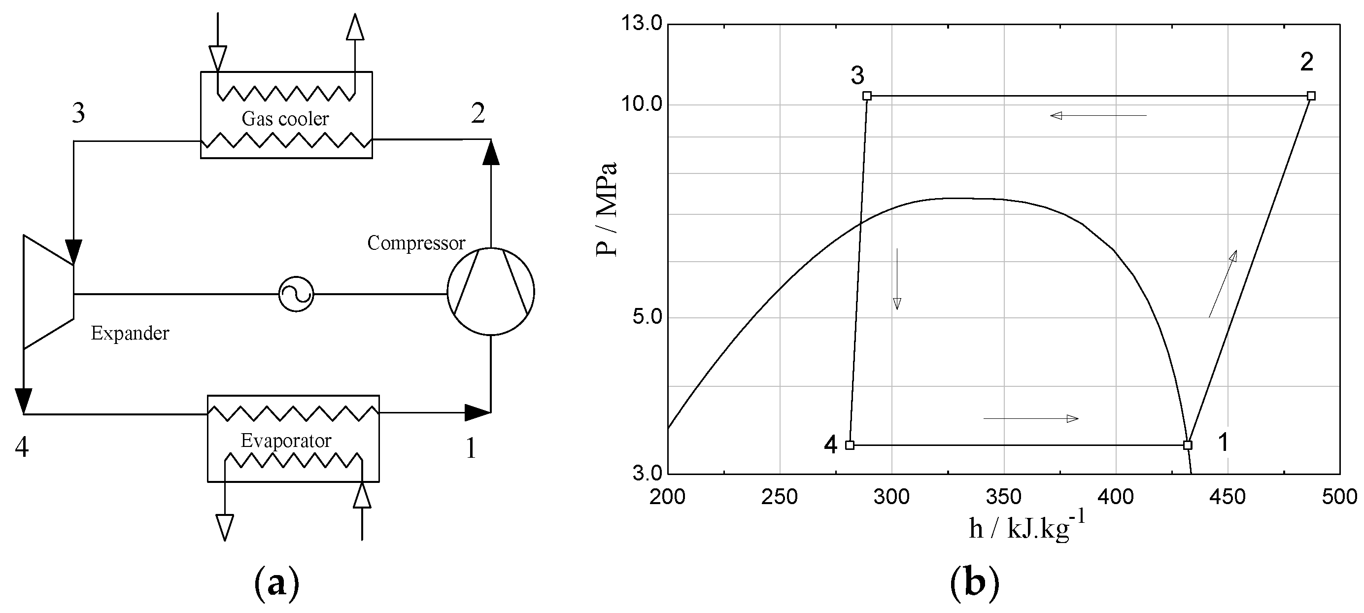
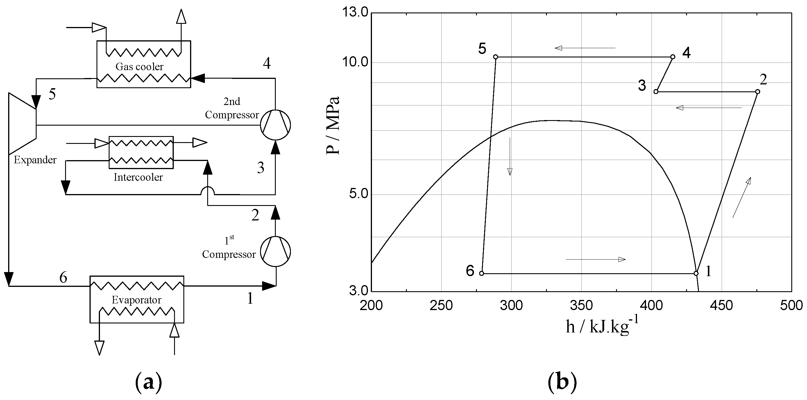
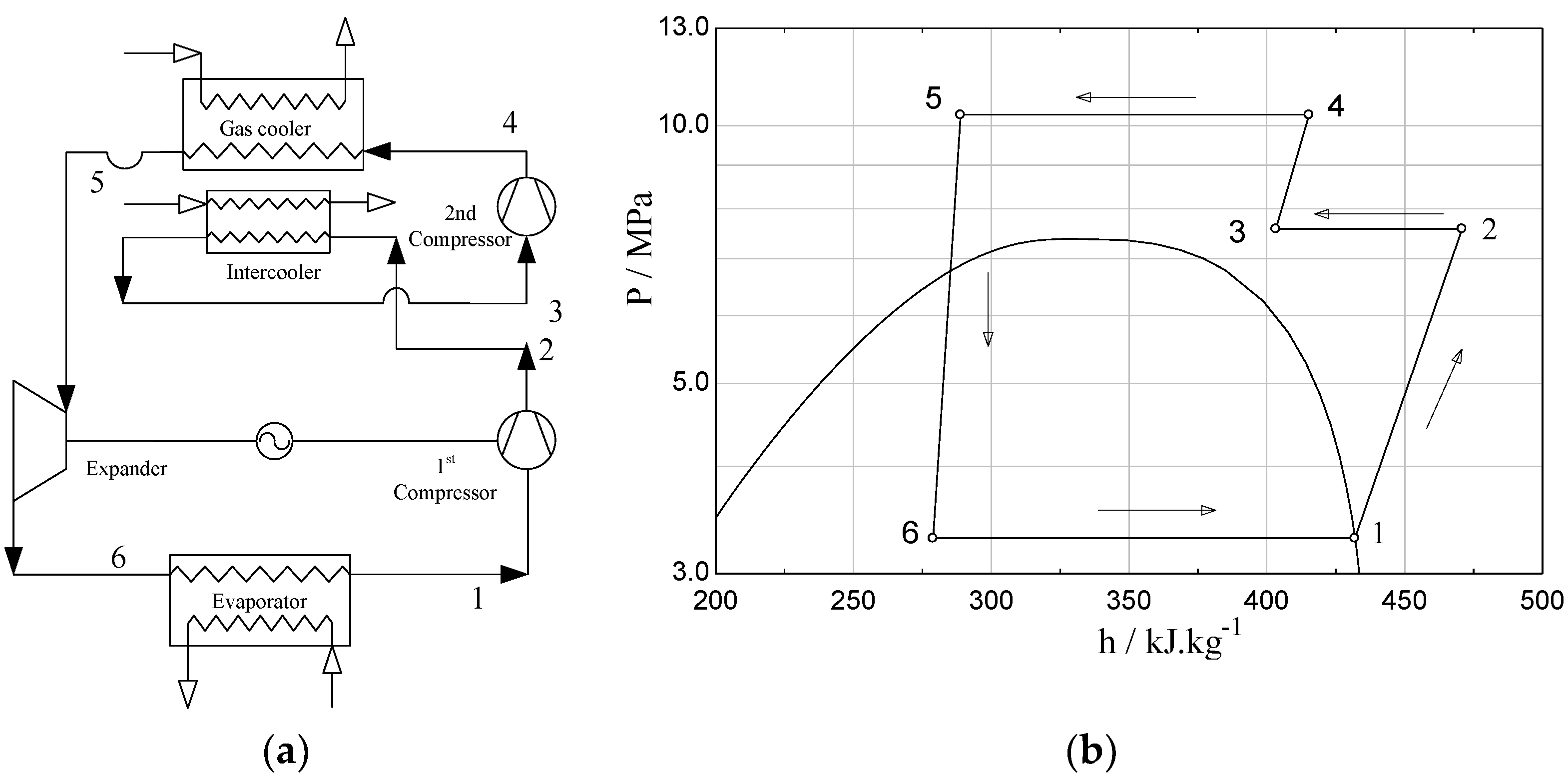
Three typical expander-based transcritical CO2 systems were modelled by applying the energy conservation to all the components of the system, typically including the compressor, expander, gas cooler and evaporator. Each component was treated as a control volume. The following assumptions were made as the simulation model was established:
- (i)
The thermodynamic processes in all of the components are steady-state ones, and the kinetic and potential energies are negligible.
- (ii)
The compression process is non-isentropic, and its isentropic efficiency is given by an empirical correlation.
- (iii)
The state at the evaporator outlet is saturated.
- (iv)
The heat loss and pressure drops in the piping connecting the components are negligible.
- (v)
Heat transfer between the components and the ambient are not accounted for.
The isentropic efficiency of the expander is taken to be 0.6 according to the reports [
5,
9,
12].
3.1. Refrigeration Capacity in the Evaporator
The specific refrigeration capacity equations for the three cycles were as follows:
3.2. Input Work and Isentropic Efficiency of the Compressor
The input work of each cycle can be calculated using the following formula:
For the TEDSC cycle, the input work of the second-stage compressor was calculated firstly according to the assumed inter-stage pressure in the given conditions. Then it was checked to see if the value agreed with the output work of the expander. If not, a new calculation was carried out after altering the inter-stage pressure. The trial calculation continued until the input work of the second-stage compressor coincided with the expander output work, and then the input work of the compressors could be acquired.
The isentropic efficiency of the compressor was used to calculate the compression work as follows:
where,
was calculated from the following correlation [
4]:
3.3. Output Work of the Expander
The output work of expander in each cycle was obtained as follows:
3.4. Coefficient of Performance
If CO
2 state at each point in the transcritical CO
2 cycles is known, the COP of the considered cycles can be obtained by:
3.5. Calculation of the Maximum COP
The previous research results showed that the optimal high side pressure and the optimal inter-stage pressure exist for the expander-based transcritical CO
2 cycles [
4,
6]. For the SE cycle, an iterations of calculating COP was carried using dichotomy method for the gas cooler inlet pressure from 8 MPa to 14 MPa to find its maximum COP under a certain working conditions.
In TEDSC cycle, the speed ratio of the second-stage compressor to the expander was constant when the components in the cycle were determined, as described in Yang’s statements [
6]. During the operation, the mass flow rate through the first-stage compressor, the second-stage compressor and the expander was equivalent, meanwhile the power consumption of the second-stage compressor was limited by the output work of the expander. As a result, the inter-stage pressure was determined when the gas cooler inlet pressure was fixed at given temperatures at evaporator inlet and gas cooler outlet. Therefore, two nested iterations were required to calculate the maximum COP. In the outer iterations, the gas cooler inlet pressure was supposed increasing gradually from 8 MPa to 14 MPa. In the inner iterations, the inter-stage pressure was calculated using the dichotomy method based on mass flow conservation and energy conservation between the expander and the second-stage compressor. By comparing the COP got in each loop, the maximum COP was gained.
In the TEADFC cycle, the expander was not combined with the first-stage compressor, so the inter-stage pressure could be adjusted when the gas cooler inlet pressure was determined. Therefore, two nested iterations were also implemented to find the maximum COP. In the first loop, the gas cooler inlet pressure was supposed gradually increasing from 8 MPa to 14 MPa. In the second loop, a provisional maximum COP was calculated increasing the inter-stage pressure from the outlet pressure of evaporator to the gas cooler inlet pressure on the basis of mass flow conservation. During the calculation, the provisional maximum COP was continuously replaced by higher one. Finally, the maximum COP could be obtained.
3.6. Relative Sensitivity
Thermodynamic analysis on transcritical CO
2 cycles was commonly done by the curves of COP versus the considered parameters, which can directly and clearly reflect their performance. However, the impact amplitude of parameters on COP can only be judged roughly by the slope of curves, which makes it difficult to rank the influence of different parameters on COP. Therefore, the relative sensitivity defined by Equation (12) was applied in the current study. It is a dimensionless quantity that facilitates the comparison between the influences of considered parameters [
22]:
where,
are the operating parameters of concern,
are the parameter values at the baseline state point, and COP
i,0 is the coefficient of performance at the baseline state point. It should be noted that the Kelvin scale was used for the temperature.
From the above definition, it can be seen that the higher the relative sensitivity is, the greater the effect of the parameter on the COP has. Furthermore, the parameter has a positive effect on the COP when its sensitivity is greater than zero, and vice versa. Optimum COP appears as the parameter sensitivity is equal to zero. Therefore, the relative sensitivity indicates how the COP of the cycle is sensitive to the varied parameter.
3.7. Calculation of CO2 Thermodynamic Properties
The simulation programs for the mentioned expander-based transcritical CO
2 cycles were developed in FROTRAN (Version 6.5, Compaq, Houston, TX, USA) language. The evaluation of CO
2 thermodynamic property was carried out using the subroutines of the NIST REFPROP 9.0 FORTRAN (Version 9.0, NIST, Gaithersburg, MD, USA) code [
23]. However, the calculation of CO
2 thermodynamic property at some points near the critical point may be unstable. So many discrete property values in a zone near the critical point (7 MPa <
P < 8 MPa, 28 °C <
T < 38 °C) were calculated in advance using Engineering Equation Solver (EES) [
24]. The CO
2 property values were calculated by interpolation in this region, whose errors were less than 0.1% compared with the EES calculated data.
4. Results and Discussion
For the three typical expander-based transcritical CO
2 cycles (SE, TEDSC and TEADFC), a simulation model was developed to obtain maximum COP, and then the parameter sensitivity analysis on maximum COP was conducted. According to [
5] and considering the application area of transcritical CO
2 refrigeration cycle, such as refrigerator and air conditioning. The relative sensitivities were obtained at various evaporator inlet temperatures (from −26.1 °C to 21.1 °C), gas cooler outlet temperatures (from 30 °C to 50 °C) and gas cooler inlet pressures (from 8 MPa to 14 MPa). When calculating the sensitivity of a parameter, other parameters remain unchanged exclude gas cooler inlet pressure and inter-stage pressure. The purpose of this is to avoid the influences from the variations of other parameters. The results regarding the sensitivity of maximum COP to the operating conditions are discussed as follows.
4.1. Sensitivity of Maximum COP to Gas Cooler Inlet Pressure
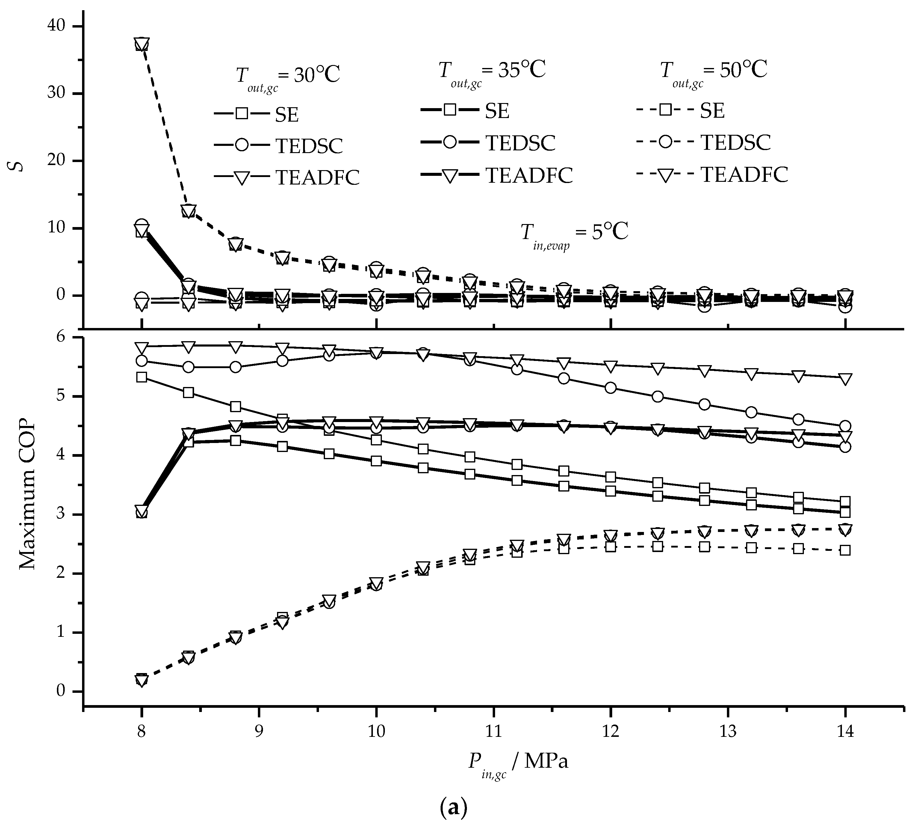
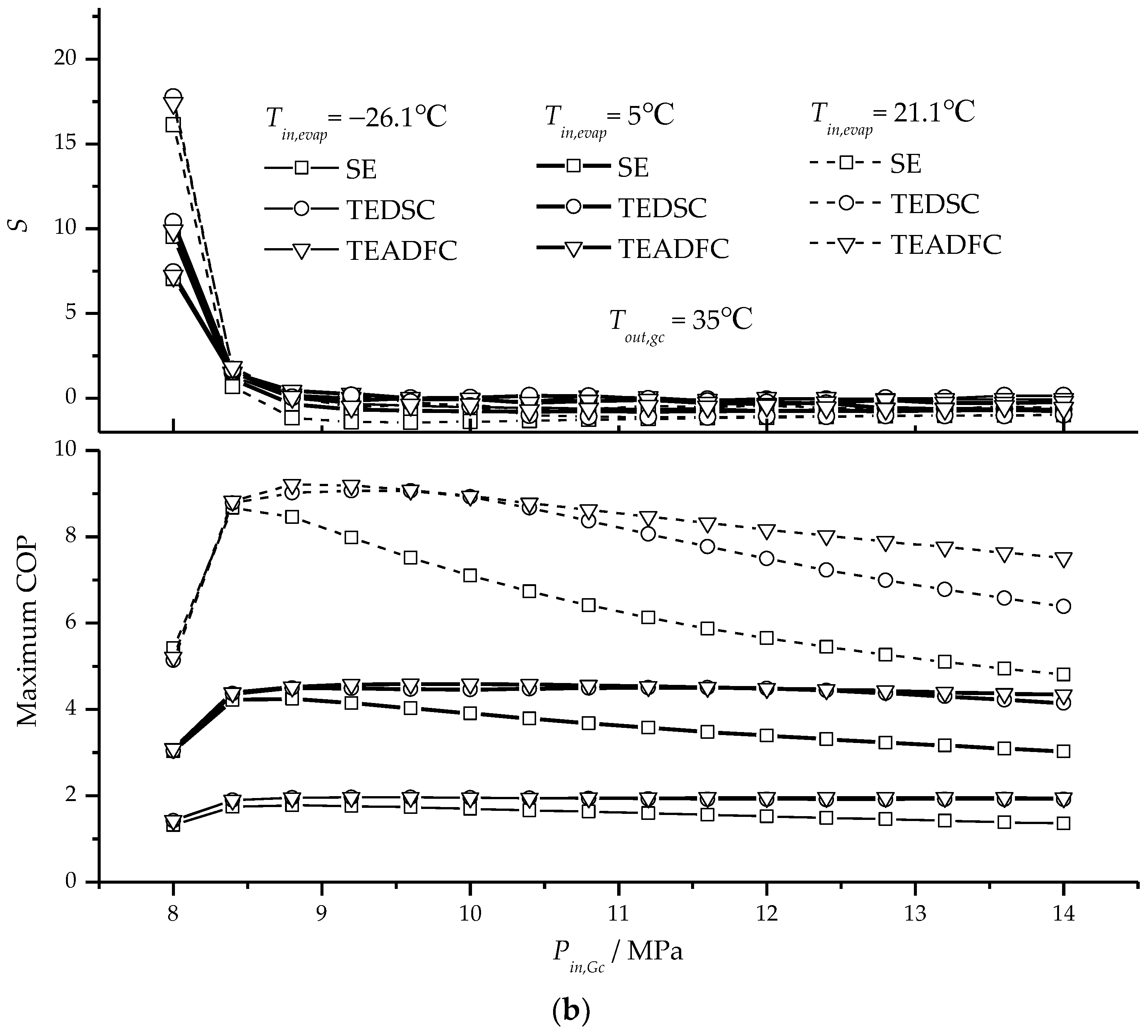
Figure 4 shows the changes of COP as well as its sensitivity to the gas cooler inlet pressure versus the gas cooler inlet pressure at various gas cooler outlet temperatures or evaporator inlet temperatures. It can be seen that the variations of sensitivity have the same trend for the three typical cycles. The optimal gas cooler inlet pressure is a critical point, which divides the range of gas cooler inlet pressure into two parts. Before the optimal gas cooler inlet pressure, the sensitivity varies greatly with an increase in the gas cooler inlet pressure, and after the gas cooler inlet pressure exceeds the optimal value, the sensitivity keeps almost constant approaching zero.
As shown in
Figure 4a, at the given evaporator inlet temperature of 5 °C and gas cooler outlet temperature of 35 °C, the sensitivity drops sharply from about 10 to zero as the gas cooler inlet pressure increases from 8 MPa to the optimal pressure of about 9.2 MPa. After that, the sensitivity changes little between zero and −0.8. However, as the gas cooler outlet temperature increases to 30 °C, the sensitivity only varies in a small range of −1.1~−0.4 in the whole calculation range of the gas cooler inlet pressure, which implies that the optimal gas cooler inlet pressure is smaller than 8 MPa as the gas cooler outlet temperature exceeds 30 °C.
From
Figure 4, significant influences of temperatures both at the gas cooler outlet and at the evaporator inlet on the sensitivity can be observed. However, the effects of temperatures on the sensitivities become weak after the gas cooler inlet pressure exceeds the optimal value.
There was a difference in the optimal high-side pressure of transcritical CO
2 cycle for the non-ideal compression and ideal compression. As an evaporating temperature is greater than 0 °C, the optimal pressure for non-ideal compression could be marginally higher than that for the ideal case, according to a thermodynamic basis provided by Srinivasan et al. [
20]. Since the optimal COP is much more sensitive to the gas cooler inlet pressure before the optimal gas cooler inlet pressure than after the optimal value, the high-side pressure of the transcritical CO
2 system should be a little higher than the calculated optimal value so that the actual COP approaches the optimal one if the calculation uncertainties are taken into account.
4.2. Sensitivity of Maximum COP to Evaporator Inlet Temperature
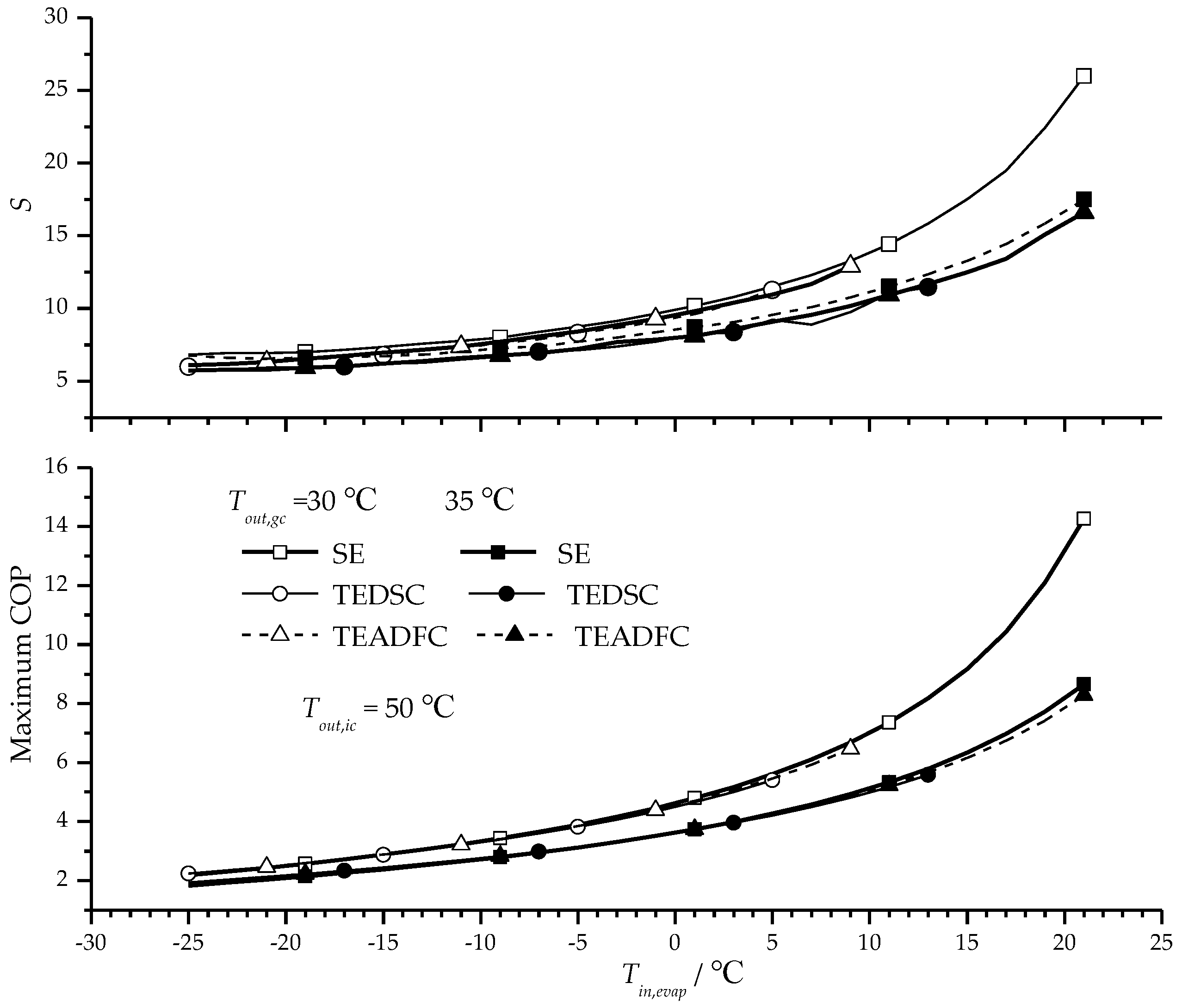
Figure 5 displays the variation of maximum COP as well as its sensitivity to the evaporator inlet temperature as the inlet temperature of evaporator increases. The trend of sensitivity variation is almost the same for the three typical cycles. Gradually faster increase in the sensitivity can be observed as the temperature at the evaporator inlet increases. As the evaporator inlet temperature increases from −25 °C to 21 °C, the sensitivity increases from 6.1 to 26.1 at the gas cooler outlet temperature of 30 °C and from 6.4 to 17.5 at the gas cooler outlet temperature of 35 °C. This indicates that the evaporator inlet temperature has a larger effect on the maximum COP at a higher evaporator inlet temperature.
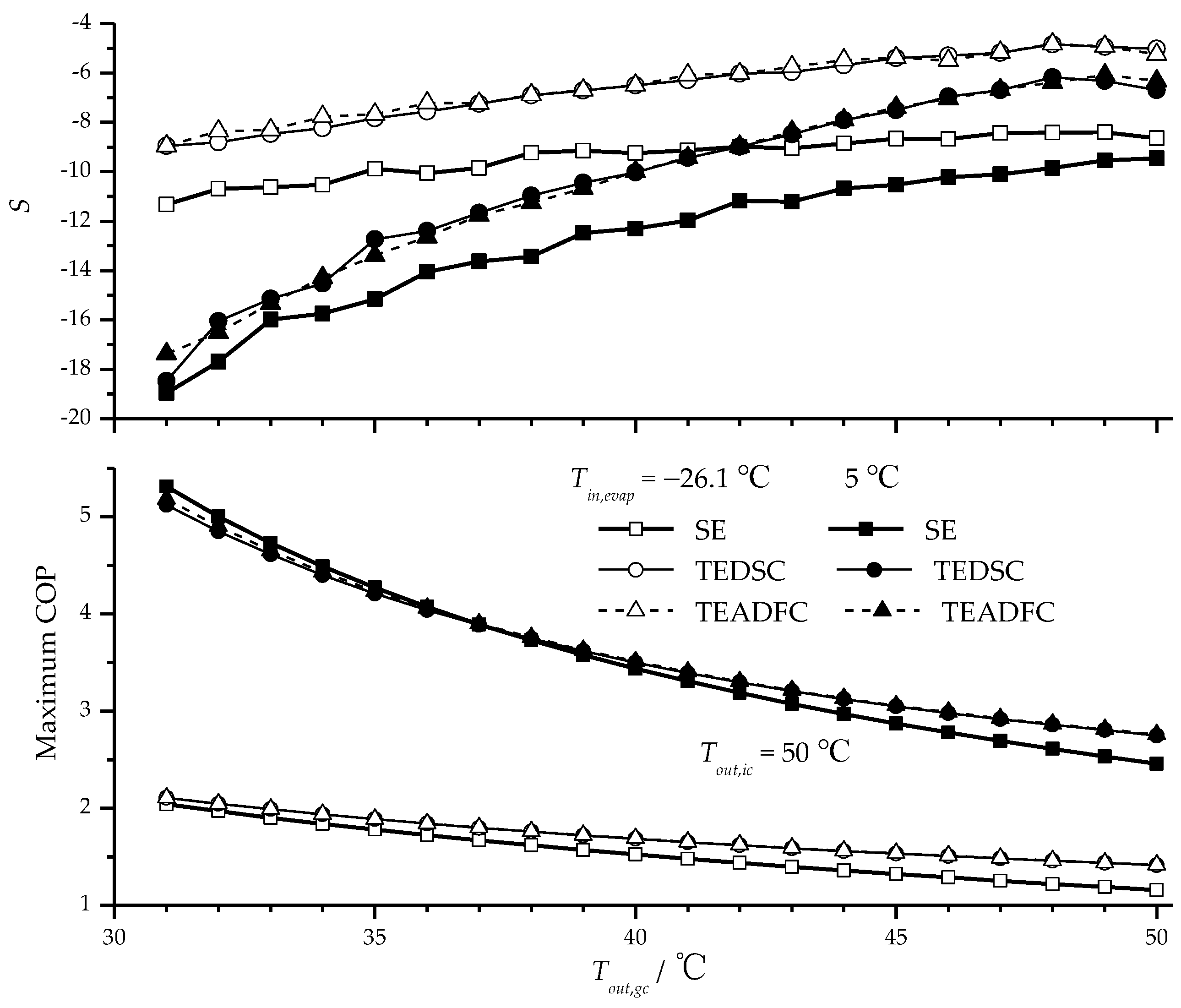
4.3. Sensitivity of Maximum COP to Gas Cooler Outlet Temperature
Figure 6 gives the variation of maximum COP as well as its sensitivity to the gas cooler outlet temperature as the gas cooler outlet temperature increases. The sensitivity is negative and increases with the gas cooler outlet temperature. Smaller absolute value of sensitivity occurs at lower evaporator inlet temperature for all the three typical cycles, which means that influence of the gas cooler outlet temperature on the maximum COP is smaller at lower evaporator inlet temperature and decreases gradually with the increased gas cooler outlet temperature.
From
Figure 6, the deviation of sensitivity between at evaporator inlet temperatures of −26.1 °C and at 5 °C reduces from 9.0 to 1.4 for the two-stage cycles (TEDSC and TEADFC) and from 7.6 to 0.8 for the sing-stage cycle (SE) as the gas cooler outlet temperature increases from 31 °C to 50 °C. This suggests that the sensitivity of the maximum COP to the gas cooler outlet temperature approaches gradually at higher gas cooler outlet temperature for various evaporator inlet temperatures.
From
Figure 6 it can also be found that the sensitivity for TEDSC and TEADFC cycles are very close and the absolute values are smaller than that of SE. In the calculation range of gas cooler outlet temperature, the absolute value of sensitivity of the two-stage cycles is 2.8 and 2.3 on average lower than that of the single-stage cycle at evaporator inlet temperatures of −26.1 °C and 5 °C. As a result, the gas cooler outlet temperature has a smaller effect on the maximum COP in the two-stage cycle than in the single-stage cycle.
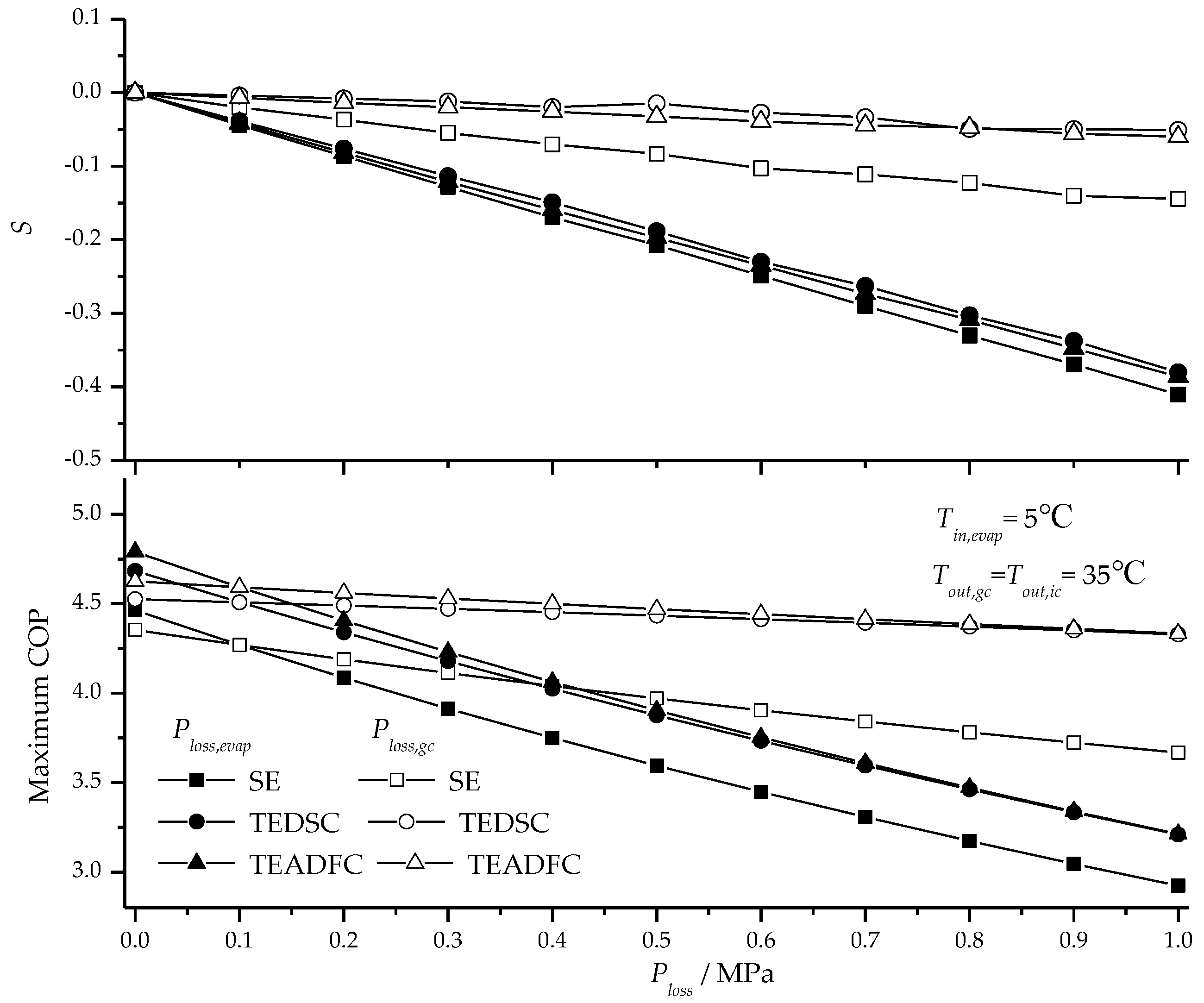
4.4. Sensitivity of Maximum COP to Pressure Losses through Gas Cooler and Evaporator
Figure 7 describes the variation of maximum COP as well as its sensitivity to the pressure losses through the gas cooler and evaporator versus the pressure drop through the gas cooler and evaporator. It is obvious that sensitivity changes linearly with the pressure drop with a negative slope. As the pressure drop increases, the sensitivity of the maximum COP to the pressure loss through the evaporator decreases much faster than through the gas cooler. Moreover, with the sensitivity of the three cycles compared, it can be found that the sensitivities for TEDSC and TEADFC cycles are very close and the sensitivity of SE reduces faster with the increased pressure loss, especially through the gas cooler. With the same pressure loss of 1 MPa, the absolute value of the sensitivity for SE cycle is approximately 7% and 160% higher than that of TEDSC and TEADFC cycles through the evaporator and the gas cooler, respectively.
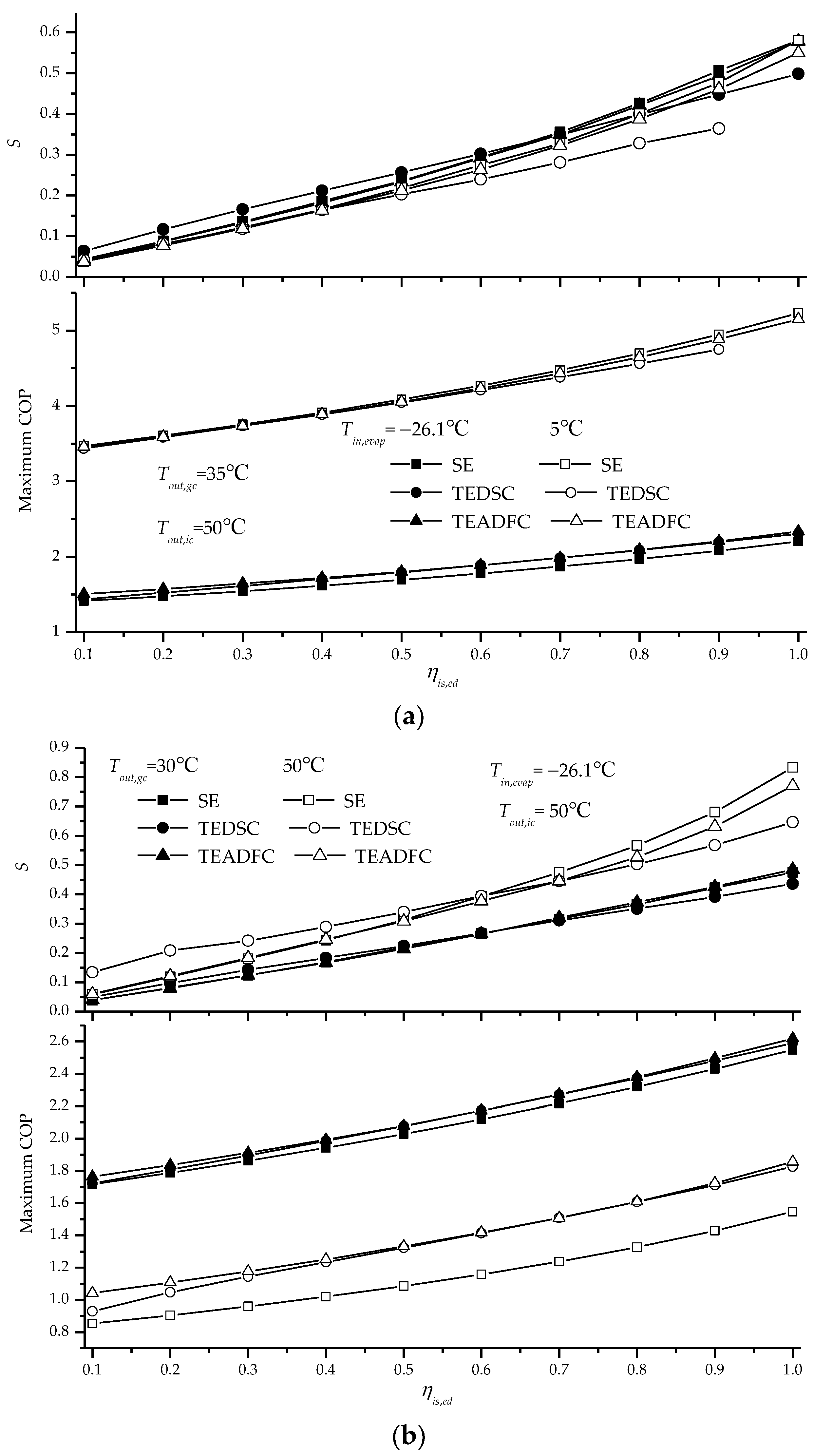
4.5. Sensitivity of Maximum COP to Isentropic Efficiency of Expander
As many studies stated, the isentropic efficiency of expander plays an important role in improving COP of the transcritical CO
2 cycle. From
Figure 8, it can be observed that the sensitivity of maximum COP to the isentropic efficiency of expander increases linearly with the increasing isentropic efficiency of expander. The slope of the sensitivity keeps almost the same at various evaporator inlet temperatures, whereas steeper increase trend of the sensitivity is observed at higher gas cooler outlet temperature.
The sensitivity curves for SE and TEADFC are very close, but the sensitivity for TEDSC is more modest. This is caused by the fact that the inter-stage pressure, determined by the isentropic efficiency of expander in TEDSC, departs from the optimal inter-stage pressure.
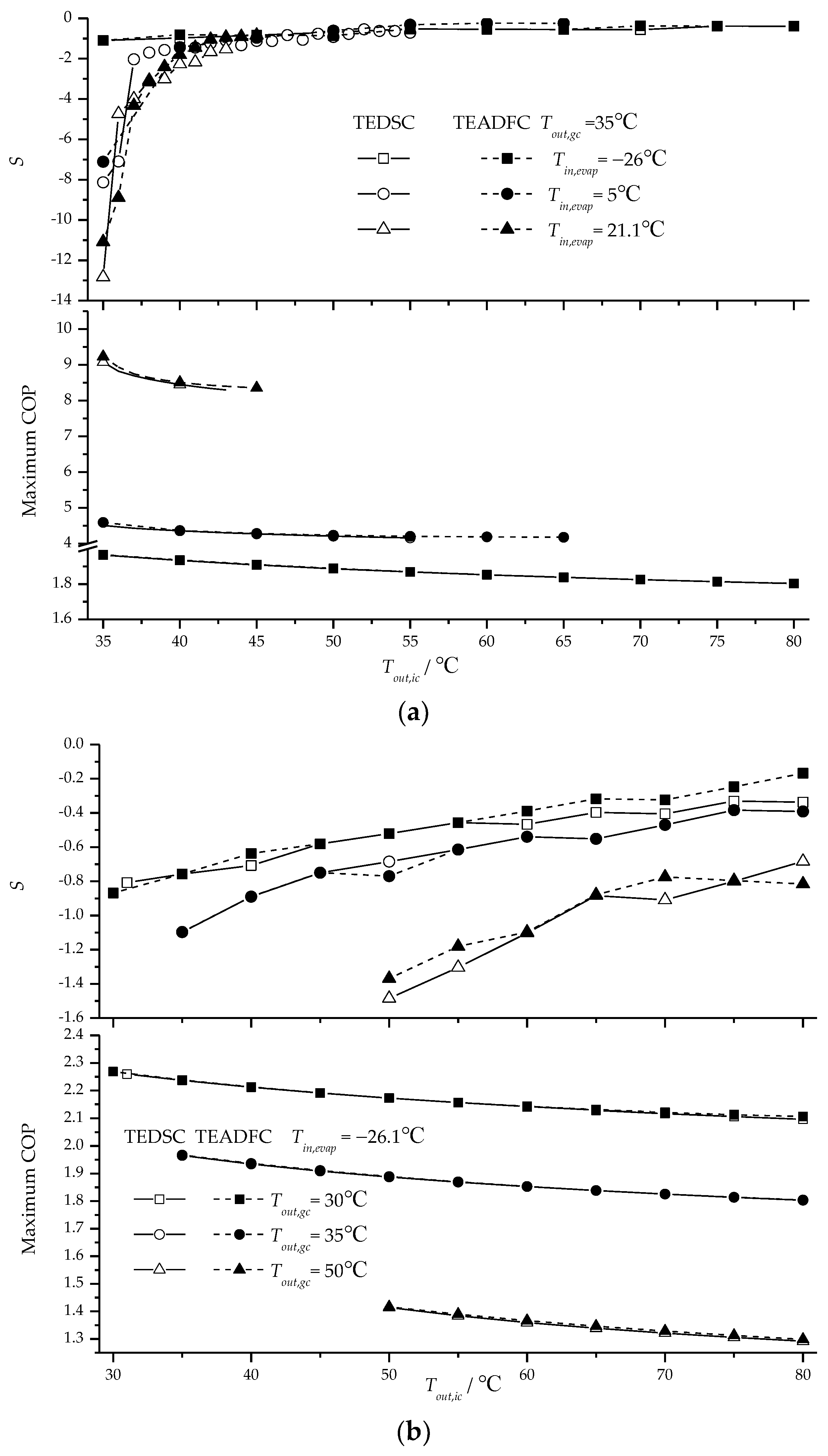
4.6. Sensitivity of Maximum COP to Temperature at Intercooler Outlet
Figure 9 shows the maximum COP as well as its sensitivity to the intercooler outlet temperature as the temperature at intercooler outlet increases. The sensitivity is less than zero, which means that temperature at intercooler outlet has a negative effect on the maximum COP. From
Figure 9a it can be seen that the sensitivity increases sharply from a low value to nearly zero as the intercooler outlet temperature increases from 35 °C to 45 °C, but there is a marginal variation in sensitivity as the temperature changes from 45 °C to 80 °C at various evaporator inlet temperatures. However, the sharp change of sensitivity becomes weak and disappears finally with the decreased evaporator inlet temperature. For example, at the evaporator inlet temperature of −26.1 °C, the sensitivity varies from −1.1 to −0.4 as the intercooler outlet temperature changes from 35 °C to 80 °C.
Figure 9b presents the variation maximum COP as well as its sensitivity to the intercooler outlet temperature at various gas cooler outlet temperatures as the evaporator temperature is kept at −26.1 °C. A slight increase of sensitivity is observed over the calculation range of intercooler outlet temperature.
The above analysis shows that the intercooler outlet temperature has little effect on the maximum COP when the intercooler outlet temperature is higher than 45 °C or evaporator inlet temperature is very low. As a result, in order to improve the maximum COP effectively, the intercooler outlet temperature should be decreased at least lower than 45 °C for the two-stage cycles.
4.7. Sensitivity of Maximum COP to Inter-Stage Pressure in TEADFC Cycle
The inter-stage pressure is an important parameter to be optimized for the two-stage transcritical CO
2 cycle.
Figure 10,
Figure 11,
Figure 12,
Figure 13,
Figure 14,
Figure 15,
Figure 16 and
Figure 17 present the variations of maximum COP as well as its sensitivity to the inter-stage pressure at different operating parameters, including the evaporator inlet temperature, gas cooler outlet temperature, intercooler outlet temperature and gas cooler inlet pressure.
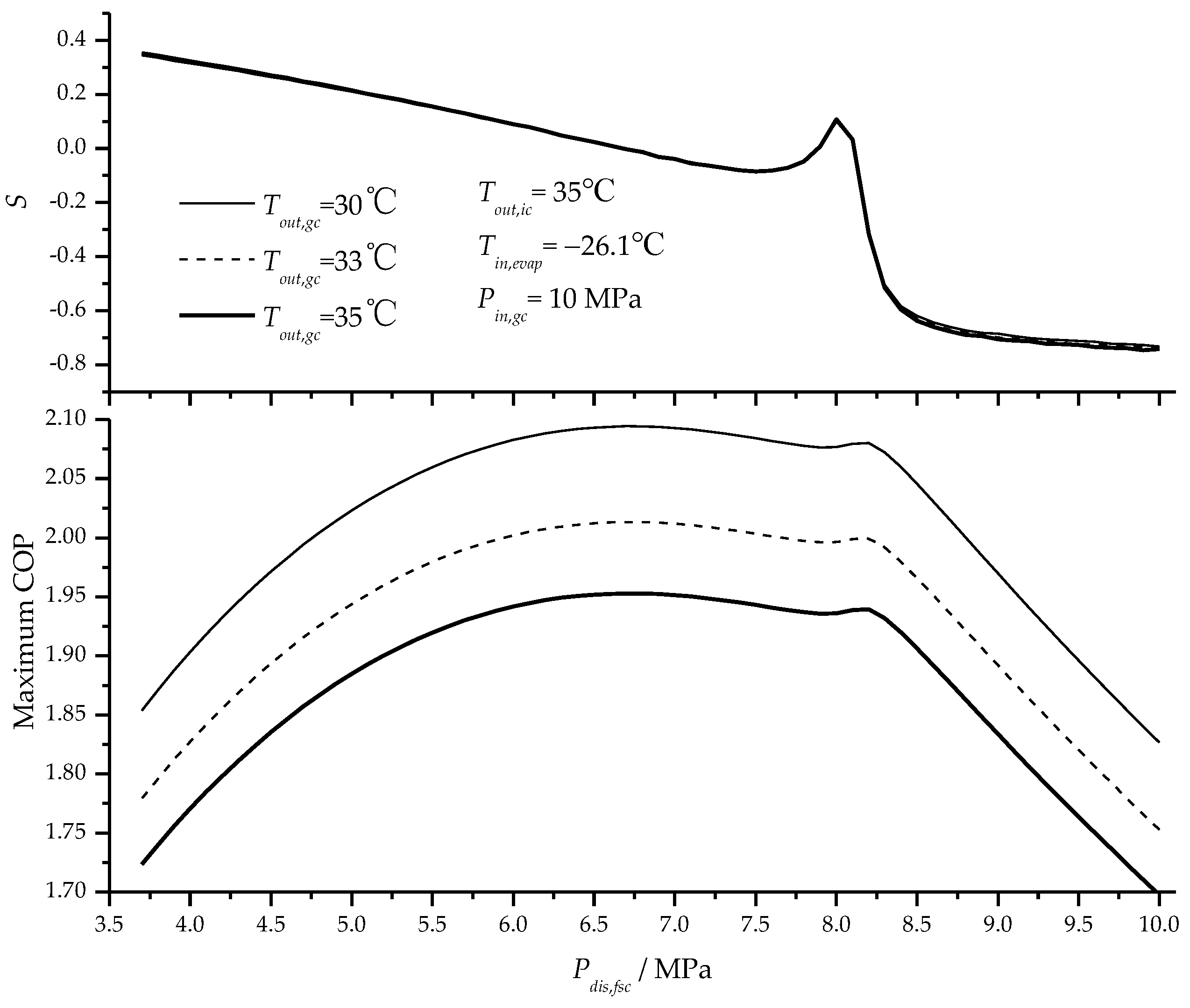
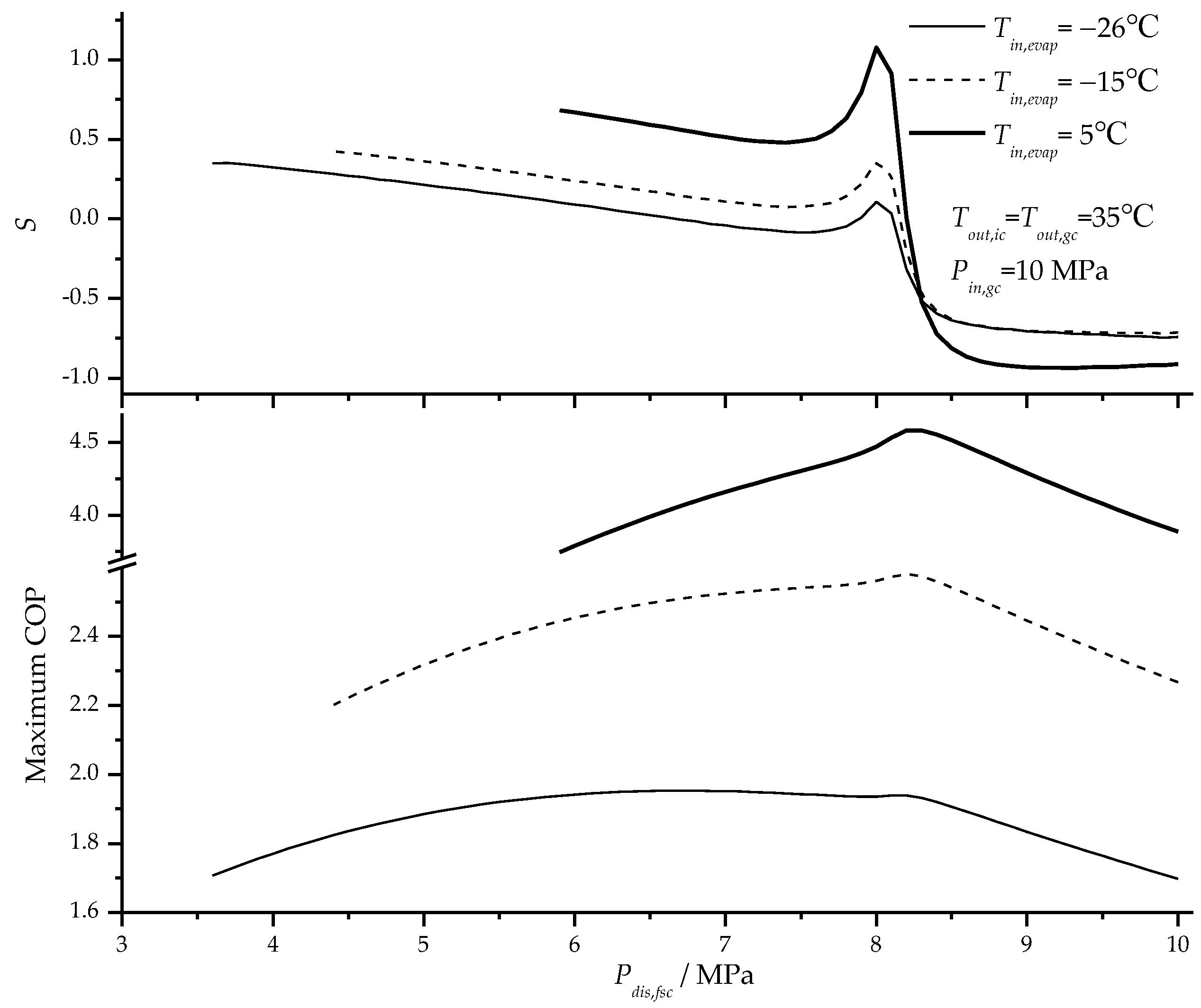
As shown in
Figure 10, a slow decrease in the sensitivity of maximum COP with the increased inter-stage pressure is observed, and then a sharp increase occurs at the inter-stage pressure of about 8.0 MPa, followed by a quick decrease to a negative value. Finally a slight variation of sensitivity is observed as the inter-stage pressure increases. The abrupt change in the sensitivity may lead to double peaks of the maximum COP, such as the plot at the evaporator temperature of −26.1 °C, which cause some obstacles to optimize the inter-stage pressure. Furthermore, the absolute value of the sensitivity decreases with the reducing evaporator inlet temperature, and the amplitude of the abrupt change decreases as well. From
Figure 10, it can also be found that the location of the abrupt change almost has no relations with the evaporator inlet temperature.
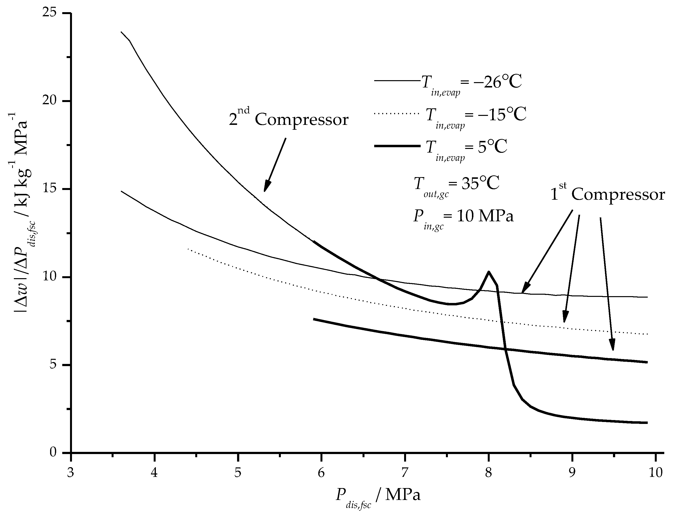
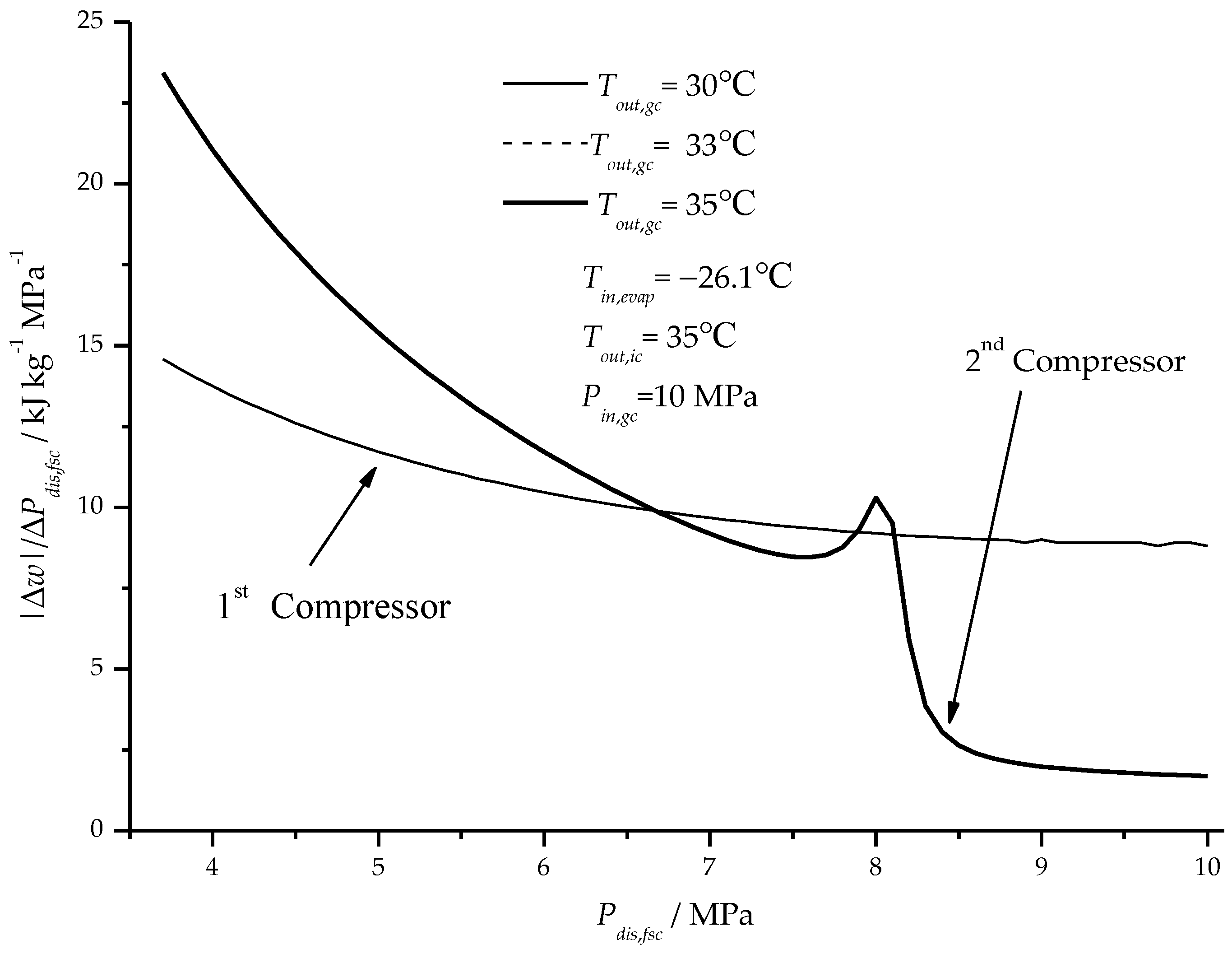
Figure 11 presents the variation rates of the specific compression work for the first- and second-stage compressor at various evaporator inlet temperatures. A sudden change in the change rate of the second-stage specific compression work occurs, which thereby causes the sharp change of the sensitivity. From
Figure 11, it can be seen that the change rate for first-stage specific compression work increase with the decreased evaporator inlet temperature, and the change rate of the second-stage specific compression work has the same trend but decreases faster. At lower evaporator inlet temperature, the change rate of the first-stage compression work increases, and the effect of the second-stage compression work on COP is weaker. Generally, the sudden change in the change rate of the second-stage specific compression work can be attributed to the phenomenon of the pseudo-critical temperature of CO
2.
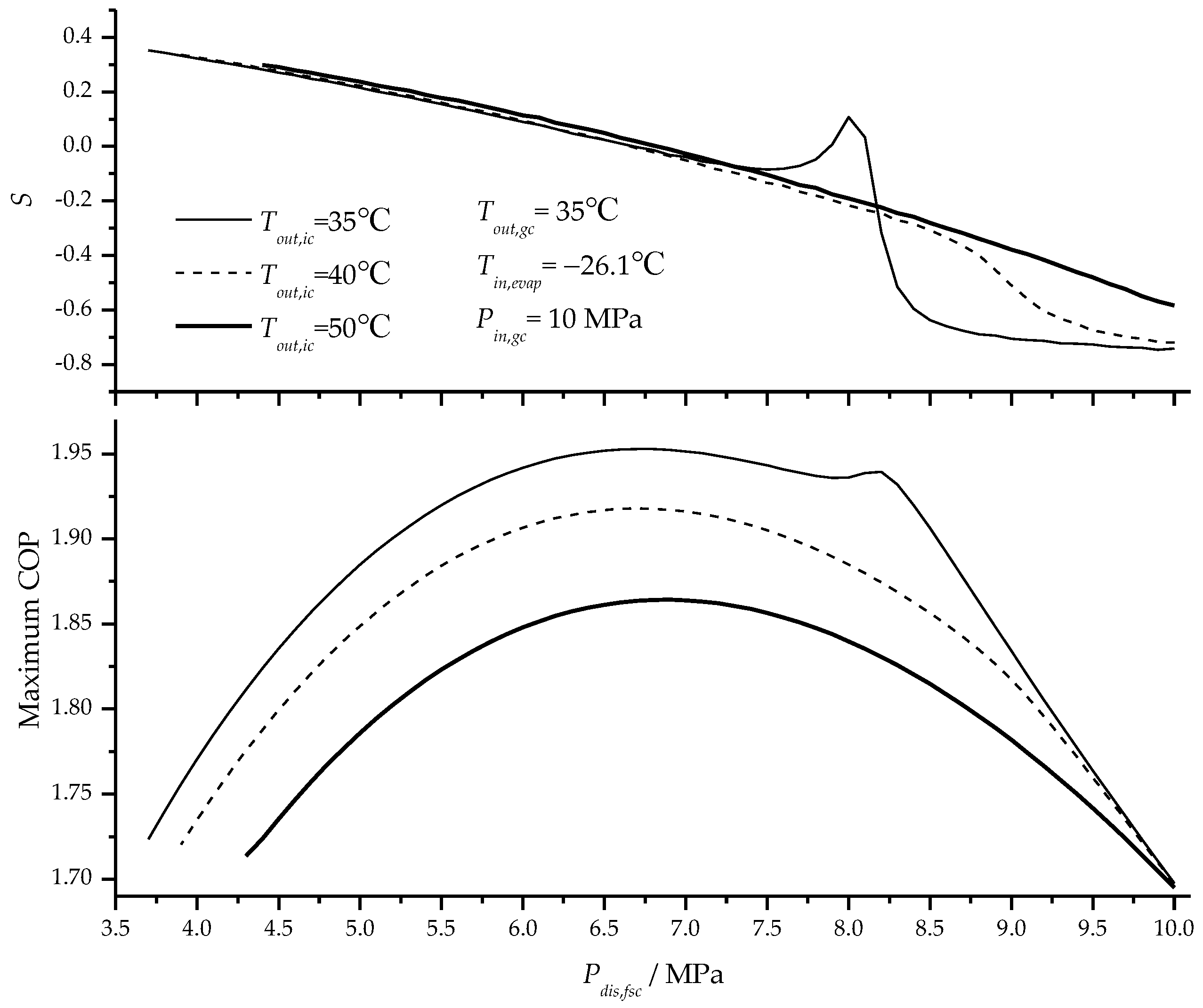
As shown in
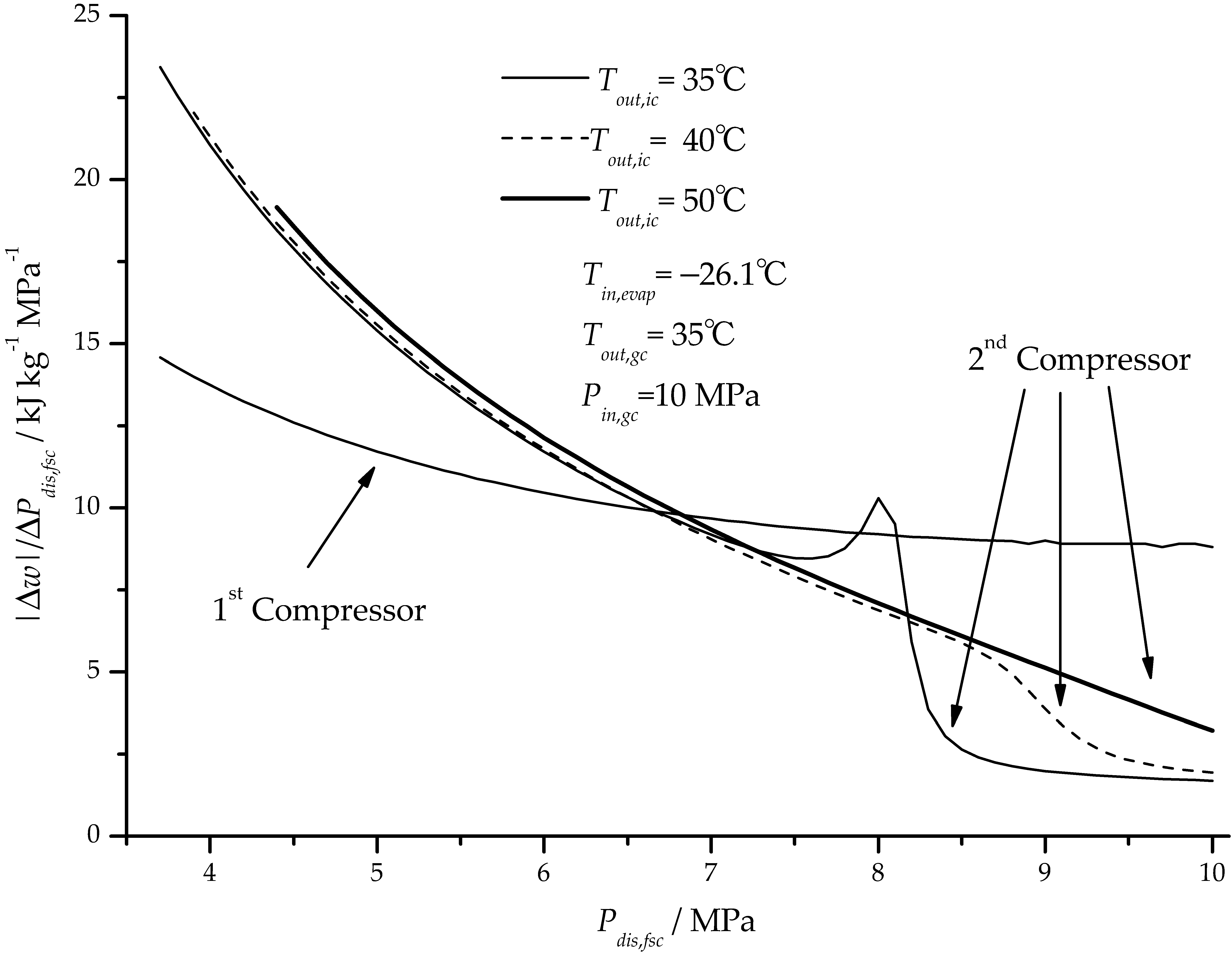
Figure 12, the sudden change in the sensitivity weakens gradually as the intercooler outlet temperature increases and disappears completely after the intercooler outlet temperature reaches about 50 °C. It is also found that the intercooler outlet temperature affects not only the amplitude of this sudden change but also its position. As the intercooler outlet temperature increases from 35 °C to 40 °C, the inter-stage pressure for the sudden change in the sensitivity to occur increases from 8 MPa to 8.8 MPa, which should be attributed to the steep change rate of the second-stage specific compression work at the corresponding pressures, as shown in
Figure 13.
From
Figure 14, it can be seen that the gas cooler outlet temperature has no effect on the sensitivity of maximum COP to the inter-stage pressure, which can be explained by the fact that the variation in gas cooler outlet temperature just affects the capacity of evaporator but has no influence on the first- and second-stage compression power, as shown in
Figure 15.
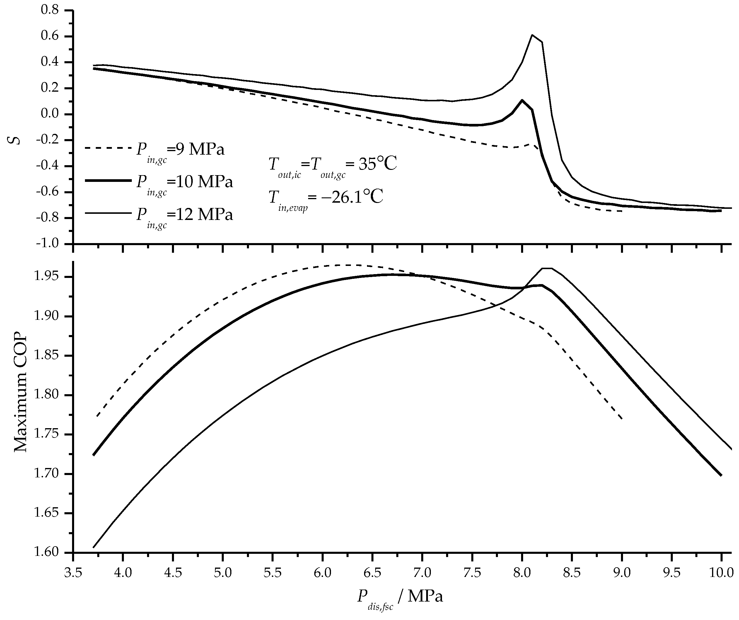
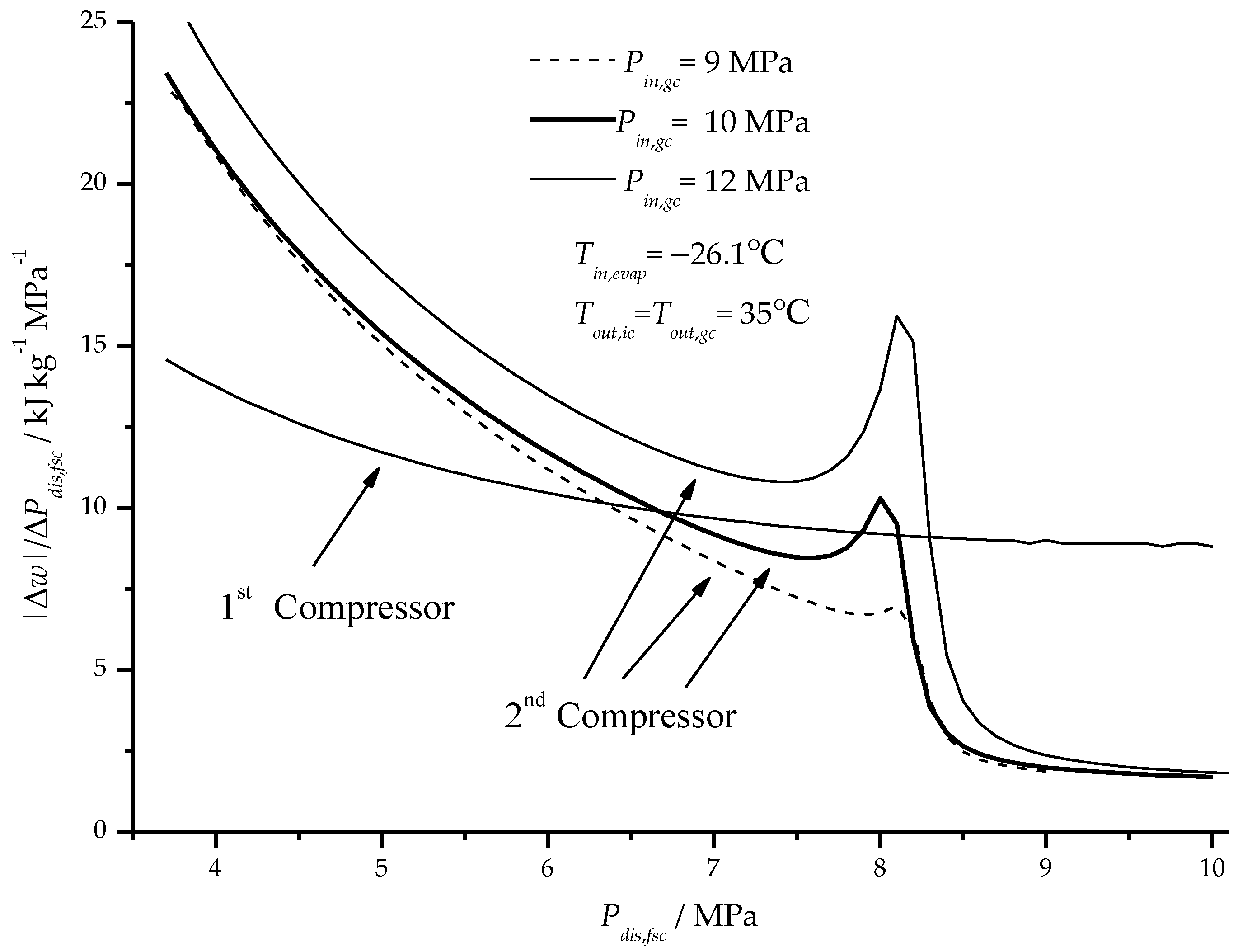
As shown in
Figure 16, the gas cooler inlet pressure has little effect on the position of the sudden change of the sensitivity, but can affect the amplitude of the sudden change. It can be explained by the fact that the abrupt change of the second-stage compression power becomes smaller with an increase in the gas cooler inlet pressure, which is shown in
Figure 17.


