Article

Hybrid Solar-Geothermal Energy Absorption Air-Conditioning System Operating with NaOH-H2O—Las Tres Vírgenes (Baja California Sur), “La Reforma” Case

by
Yuridiana Rocio Galindo-Luna
1,
Efraín Gómez-Arias
2,
Rosenberg J. Romero
3,*,
Eduardo Venegas-Reyes
4,
Moisés Montiel-González
5,
Helene Emmi Karin Unland-Weiss
6,
Pedro Pacheco-Hernández
6,
Antonio González-Fernández
7 and
Jorge Díaz-Salgado
8
1
Engineering and Applied Science Postgraduate School, Morelos State Autonomous University (UAEM), Morelos 62209, Mexico
2
CONACYT-Division of Earth Sciences, Center for Scientific Research and Higher Education of Ensenada, Baja California C.P. 22860, Mexico
3
Engineering and Applied Sciences Research Centre, Morelos State Autonomous University (UAEM), Morelos 62209, Mexico
4
CONACyT-Research Center of Advanced Materials (CIMAV), Durango 34000, Mexico
5
School of Chemical Science and Engineering, Morelos State Autonomous University (UAEM), Morelos 62209, Mexico
6
Mexican Institute for Water Technologies (IMTA), Paseo Cuauhnáhuac 8532, Progreso C. P. 62550, Jiutepec Morelos, México
7
Division of Earth Sciences, Center for Scientific Research and Higher Education of Ensenada, Baja California C.P. 22860, Mexico
8
Ecatepec Technological Higher Studies TESE Av. Tecnológico S/N, Col. Valle de Anáhuac, Ecatepec Edo. de Mexico 55210, Mexico
*
Author to whom correspondence should be addressed.
Energies 2018, 11(5), 1268; https://doi.org/10.3390/en11051268
Submission received: 27 March 2018 / Revised: 1 May 2018 / Accepted: 8 May 2018 / Published: 16 May 2018
(This article belongs to the Section L: Energy Sources)

Abstract

:
Solar and geothermal energies are considered cleaner and more useful energy sources that can be used to avoid the negative environmental impacts caused by burning fossil fuels. Several works have reported air-conditioning systems that use solar energy coupled to geothermal renewable energy as a thermal source. In this study, an Absorption Air-Conditioning System (AACS) used sodium hydroxide-water (NaOH-H2O) instead of lithium bromide-water to reduce the cost. Low enthalpy geothermal heat was derived from two shallow wells, 50 and 55 m deep. These wells are of interest due to the thermal recovery (temperature vs. time) of 56.2 °C that was possible at the maximum depth, which can be used for the first stage of the process. These wells were coupled with solar energy as a geothermal energy application for direct uses such as air-conditioning systems. We studied the performance of an absorption cooling system operating with a NaOH-H2O mixture and using a parabolic trough plant coupled with a low enthalpy geothermal heat system as a hybrid heat source, as an alternative process that can help reduce operating costs and carbon dioxide emissions. The numerical heat transfer results showed the maximum convective heat transfer coefficient, as function of fluid velocity, and maximum temperature for a depth higher than 40 m. The results showed that the highest temperatures occur at low fluid velocities of less than or equal to 5.0 m/s. Under these conditions, reaching temperatures between 51.0 and 56.2 °C in the well was possible, which is required of the geothermal energy for the solar energy process. A water stream was used as the working fluid in the parabolic trough collector field. During the evaluation stage, the average experimental storage tank temperature achieved by the parabolic trough plant was 93.8 °C on October 23 and 92.9 °C on October 25, 2017. The numerical simulation used to evaluate the performance of the absorption cycle used a generator temperature of 90 °C, a condenser and absorber temperature at 35 °C, and an evaporator temperature of 10 °C. The Coefficient of Performance was calculated as 0.71 under design conditions.

1. Introduction

The population, per capita energy consumption, and the growing economy are causing an increase in energy demands. Fossil fuels are the main contributor to global warming; awareness of this problem has been heightened, invigorating research to determine how to replace of fossil fuels by renewable and environmentally friendly energy sources [1]. The energy demand in most industrialized countries was associated with air-conditioning [2] and during warm weather periods, air-conditioning has caused peaks in electricity consumption. This situation is due to improved living conditions and demands for occupant comfort [3,4]. The air-conditioning absorption system eliminates the need for a compressor by replacing it with a generator and an absorber; therefore, electric power is not required to pressurize the refrigerant, as is the case for a conventional system [5]. Electric power is necessary for the auxiliary devices. However, the main energy supply required by the cycle as a heat input for the operation can be provided by renewable energy such as solar, geothermal, or a hybrid system combining these two energies.
Solar heat can contribute significantly to the global energy demands for air-conditioning [6,7,8,9]. In concentrating collectors, solar radiation is converted into thermal energy. According to the geometry, these systems are classified as either line-focus concentrators (parabolic-trough collectors (PTC) and linear Fresnel collectors) or point-focus concentrators (parabolic dishes and central receiver systems) [10]. PTC applications can be divided into two main groups. In the first, temperatures are attained in the range of 300 to 400 °C. The most advanced systems are concentrated solar power plants [11]. The second group supplies thermal energy between 85 and 250 °C for applications that requires these temperatures. The typical total length rank aperture widths are 1 to 3, and 2 to 10 m as total lengths [12]. Reddy and Ravi [13] described a solar parabolic trough collector field for power generation based on geometric parameters. According to the authors’ results, the optimum configuration for the Indian conditions requires six meters of aperture with a 65° rim angle. Rosado and Escalante [14] reported the performance of a parabolic trough collector using water as working fluid; they found that the maximum efficiency of the collector was 5.43% with a low flow rate of 0.022 kg/s. Venegas et al. [15] evaluated a solar PTC with a length of 4.88, rim angle of 45° m, and aperture area of 5.8 m2. The optical efficiency was close to 60%, the temperature range was 70–110 °C, and the maximum efficiency was 60%. Mazloumi et al. [16] simulated a solar single effect absorption cooling system and lithium bromide-water (LiBr-H2O) as the working fluid in Ahwaz, Iran. The collector area was 57.6 m2, and the coefficient of performance (COP) of the absorption cycle in the month of July was between 0.6 and 0.8, with the generator temperature ranging from 70 to 95 °C. Ghaddar et al. [17] analyzed a solar lithium bromide absorption system to be used in a small residential application in Beirut. A simulation program for modelling and performance evaluation showed that, for 3.52 kW, the capacity of the water storage tank ranged from 1000 to 1500 L and a minimal collector area of 23.3 m2 was needed. Baniyounes et al. [18] reported using a solar-assisted air-conditioning system for Rockhampton, Emerald and Gladstone, Central Queensland subtropical climate. The cooling load profile was obtained using TRNSYS ® software. The analysis results determined that installing a hot water storage tank of 1.8 m3 with 50 m2 of solar collectors achieved savings of 80% compared with the primary energy. Mujahid et al. [19] theoretically analysed the use of an evaporative cooling system in five cities in Saudi Arabia. According to the authors’ results, the COP varied from 0.275 to 0.476 for different locations. Florides et al. [20] reported a model to simulate a single effect absorption solar cooling system modelled with the TRNSYS program for the weather parameters in Nicosia, Cyprus. They concluded that a 0.6 m3 hot water storage tank and a 15 m2 compound parabolic collector tilted 30° from horizontal was the optimised system. Syed et al. [21] analysed a LiBr-H2O single effect 35 kW absorption system with nominal cooling capacity for use during the summer of 2003 in Madrid, in a typical house. Twenty flat-plate collector modules were used to delivered hot water with a total area of 50 m2; the measured daily average, maximum instantaneous, and period average COP were 0.42, 0.60, and 0.34, respectively. Li and Sumathy [22] evaluated a solar powered absorption air-conditioning system with a partitioned hot water storage tank. The system used 38 m2 of solar flat-plate collectors in parallel array to drive an absorption chiller that used LiBr-H2O, with a cooling capacity of 4.7 kW. The results showed a total solar cooling COP of around 0.07. Zhai et al. [23] designed and installed a mini-type solar absorption cooling system in Shanghai Jiao Tong University. The system mainly included a 96 m2 solar collector array connected in series, an absorption chiller with a cooling capacity of 8 kW, and a hot water storage tank with a capacity of 3 m3. The COP varied from 0.25 to 0.38.
Geothermal energy obtained from fluids stored in hydrothermal or conventional systems has been maturing technologically as renewable energy. Currently, 51 countries in the world generate electricity from this natural resource and 71 countries use geothermal energy for both electricity generation and for direct uses (mainly heat pumps) [24,25]. Given the geothermal resources available in the world, geothermal energy has grown exponentially in terms of installed capacity and generation of electric power. The reports in the literature indicate a production of 6830 MW in 1995 and 12,730 MW in 2015, which represents only 0.5% of the energy consumption in the world, with an output of 73,689 GWh. This is an increase of 186% in the last 10 years. The main challenges facing the geothermal industry include reducing the risks involved in drilling wells, which allows for an increase in the extraction of geothermal fluid, and an increase in the generation of electric energy [24,25]. World reports of the use of these resources indicate that the installed capacity will increase to slightly more than 21,000 MW by 2020, with an electric power generation equivalent to 85,000 GWh [24,25]. Examples have been provided in previous works. Rosiet and Batlles [26] reported the replacement of a cooling tower by a shallow geothermal system for use in a solar-assisted air-conditioning system. According to the results, the system used 31% less energy compared to the cooling tower during the cooling period and 116 m3 of water were saved during the summer. Buonomano et al. [27] designed, simulated, and optimized a micro-Organic Rankine Cycle a single stage absorption chiller that used LiBr-H2O and a solar field of flat-plate evacuated solar collectors. The results showed that it was possible to produce cooling energy, electricity, and heat with this system. Calise et al. [28] simulated a solar-geothermal polygeneration system. The plant was built to supply electrical, cooling energy, heat, and fresh water to a small community, based on an ORC integrated with a multi-effect distillation unit and driven by parabolic trough collectors. The results included exergetic, energetic, economic, and exergoeconomic performance data. Ahmadi and Chavoshi [29] analysed thermodynamic, environmental, and economic conditions of a flat plate collectors, using water-copper oxide nanofluid as the absorbing fluid, coupled to a solar-geothermal system driven by a combined heating, cooling, and power (CCHP) cycle. According to the results of the multi-objective optimisation outcomes, R1234ze was the best fluid; moreover, R423A presented the minimum total product cost rate and R134a was the best fluid for exergetic efficiency.
With respect to geothermal energy, Mexico currently ranks fourth in the world in electricity production from hydrothermal systems (after the U.S. with 3450 MW, the Philippines with 1870 MW, and Indonesia with 1340 MW). Mexico has an installed capacity of 982.3 MW and a production of 6000 GWh, representing only 2.0% of the country’s electricity consumption. The production is distributed across five geothermal fields (Figure 1), four operated by Comisión Federal de Electricidad (CFE) (Federal Electricity Commission) [24,30]: Cerro Prieto, Baja California (570 MW); Los Azufres, Michoacán (247.9 MW); Los Humeros, Puebla (118.9 MW); and Las Tres Vírgenes, Baja California Sur (10 MW). Grupo Dragón operates the fifth geothermal field called Domo San Pedro in Nayarit (35.5 MW) [24,30].
The production of geothermal energy is achieved from steam production and hot water. This technology has two options: (1) exploiting the energy source by using a shallow borehole heat exchanger and (2) heat pumps [25]. Jen-Hiu et al. [31] reported the effect of using geothermal water at 90–100 °C from a hot spring for an air-conditioning system. The results showed a 26% decrease in the total electrical consumption; 54% of the reduction was caused by the electrical energy consumed by the air-conditioning heating system, and the air host was reduced by 66.5%. Abtullah and Oguz [32] analysed 3660 different designs using an artificial neural network (ANN) to optimise geothermal energy in order to assist an absorption refrigeration system using NH3-H2O as the working fluid. According to the results, the optimum design obtained a COP of 0.5722. Pingye et al. [33] presented a geothermal system for heating and cooling services in mines based on the observed data. Compared with traditional systems, performance increased 30% by avoiding the cooling tower, and the parallel running of cooling and heating services had an improved energy efficiency of 20%. Farabi-Asl [34] performed a cooling test with a ground source heat pump at Kaita University campus for three rooms with a total area of 100 m2. The field test results showed that water pumping and injection could increase the COP by around 7% during the cooling operation.
In Mexico, the direct uses of geothermal energy are practically null; it has been reported in 20 places, being limited mainly to balneology for recreational purposes and therapeutic treatments [30]. The use of geothermal heat pumps, which is the main direct use of geothermal energy in the world, is under development. The installed capacity and the annual use of energy for the different applications of direct use are 0.460 MW for heating systems or air conditioning for buildings, 0.004 MW for greenhouse heating, 0.007 MW for the drying of agricultural products, and 155,347 MW for balneology. The total for the country is 155,818 MW [30,35]. Sites with geothermal potential of low, medium, and high enthalpy (temperature) have been identified and the CFE has established exploration programs for the evaluation of these sites (e.g., Acoculco, Puebla; Bahía Concepción, B.C.; Pathé, Hidalgo; Las Derrumbadas, Puebla; Tulechek, B.C.; Laguna Salada, B.C.; La Reforma and El Aguajito caldera volcano, B.C.S.) [36,37]. This scenario represents a great opportunity for the development of new strategies that will allow the direct use of geothermal energy in Mexico.
This paper proposes a parabolic trough collector coupled to a low enthalpy geothermal well as a hybrid thermal source for an Absorption Air-Conditioning System (AACS). This system uses sodium hydroxide-water (NaOH-H2O) to reduce the cost three-fold compared with the use of LiBr-H2O [38,39,40]. The use of solar energy as a thermal source reduces electric power consumption; PTCs are an option for the AACS thermal demand [8]. Low enthalpy geothermal heat was obtained from two shallow wells with depths of 50 and 55 m. These wells are attractive and interesting because of the thermal recovery (temperature vs. time) provided at the maximum depth (62 °C), which can be used during the first stage of the process as a geothermal energy application, coupled with solar energy, for direct uses such as air-conditioning systems. This work studied the performance of an absorption cooling system using a NaOH-H2O mixture and a parabolic trough plant coupled to a low enthalpy geothermal heat system as a hybrid heat source, as an alternative system for the reduction of operating costs and carbon dioxide (CO2) emissions. The aim was the installation analysis of an absorption air-conditioning system coupled to solar and geothermal sources far from the electrical grid.

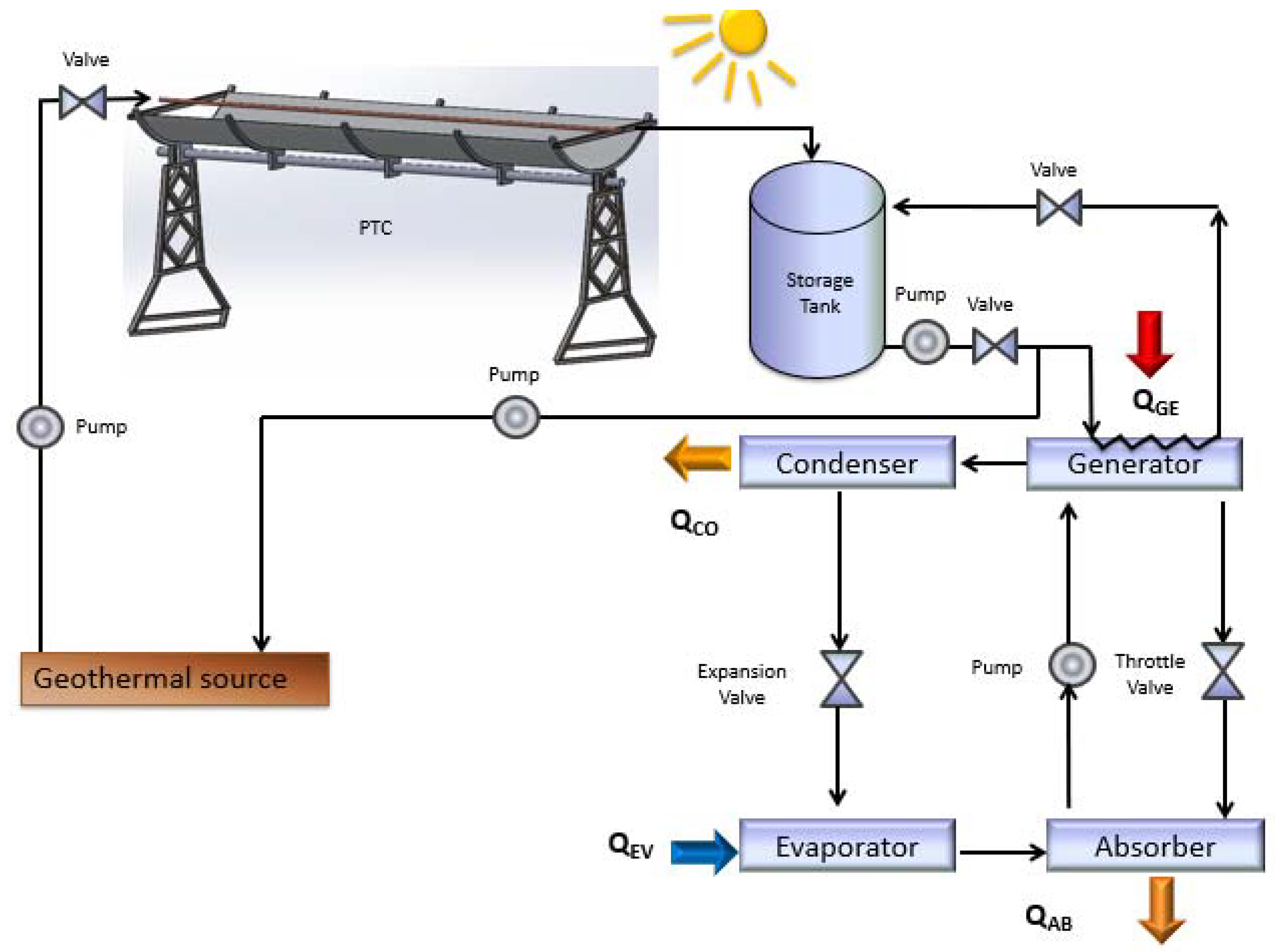
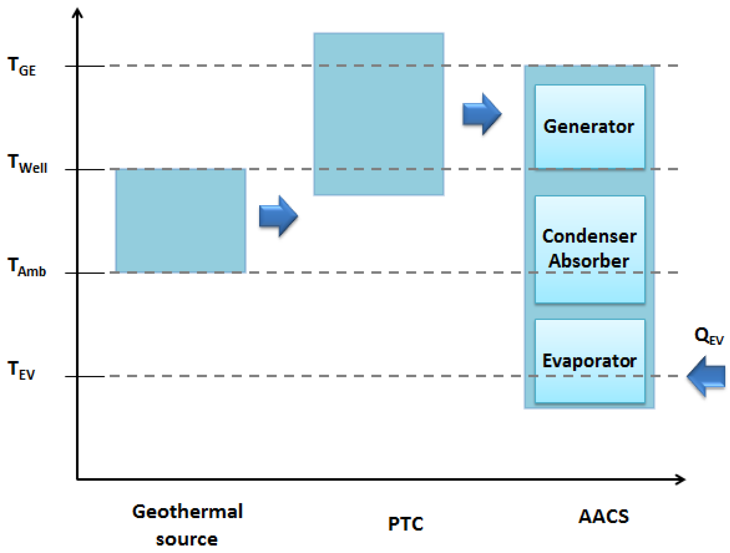
2. Description of the System

This paper proposes the use of a parabolic trough collector field that uses geothermal energy to supply thermal energy to an air-conditioning absorption system, as shown in Figure 2. The air-conditioning requirements of Santa Rosalía are being covered by means of conventional systems, so this study proposes the use of an absorption air-conditioning system due to the proximity of a geothermal energy source. The maximum registered temperature in October 2017 was 35.5 °C. The proposed system uses a low enthalpy geothermal energy source to heat the working fluid (water) up to 50 °C as shown in Figure 2. In this case, a U-tube heat exchanger was used for the transfer heat process. After that, the fluid was introduced into a parabolic trough collector field to raise its temperature over 90 °C. Finally, this heated working fluid was used as a thermal energy source for the absorption air-conditioning system.
The system temperature level diagram (Figure 3) shows that the geothermal energy source raises the working fluid temperature from the ambient temperature (z) to a well temperature (TWell) of around 63 °C, the water is introduced into a parabolic trough collector (PTC) field, raising its temperature to over 90 °C, and this temperature level is sufficient to supply thermal energy into the absorption air conditioning system (AACS) at 90 °C (TGE). The numerical simulation applied the following temperatures: 90 °C for the generator, 35 °C for the condenser and absorber (with natural convection dissipation), and 10 °C for the evaporator. This study aimed to bring air-conditioning services to any space with requirements lower than or equal to 7.05 kW (thermal load) for Santa Rosalia in Baja California Sur, Mexico.

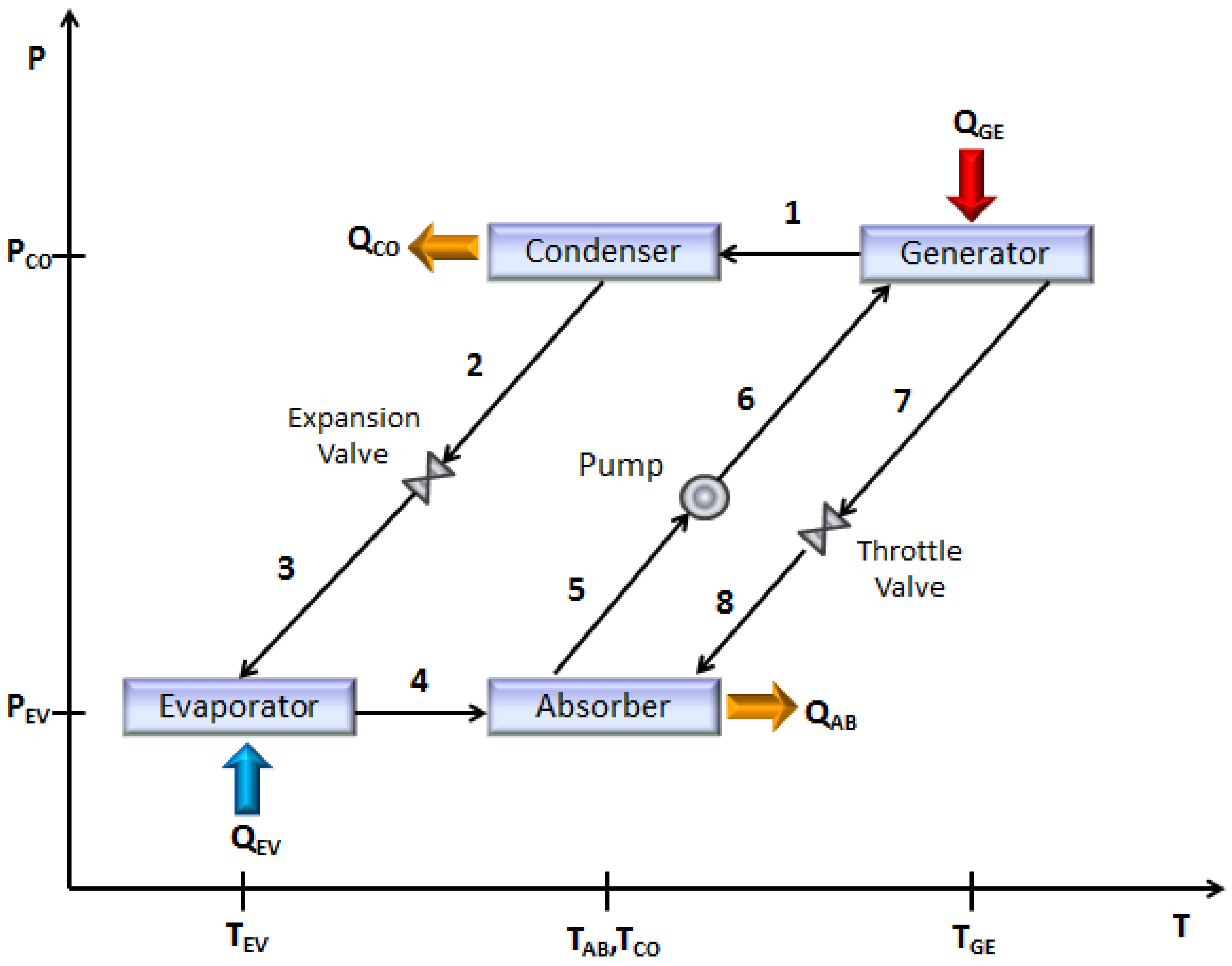
2.1. Absorption Air-Conditioning System (AACS)

The absorption heat pump type I produces a cooling effect by removing and transferring air heat inside the space to the refrigerant. The absorption air-conditioning system employs a generator, a condenser, and an evaporator and absorber. The cycle requires a refrigerant fluid and an absorbent solution. In the generator, by adding an amount of heat (QGE), (1) a portion of the refrigerant fluid is vaporised at high temperature and high pressure (PCO). (2) The steam of refrigerant is condensed through natural convection to remove heat (QCO) at ambient temperature. (3) The refrigerant fluid leaves the condenser and arrives at the evaporator through the expansion valve. (4) The refrigerant liquid arrives at the evaporator for evaporation at low temperature and pressure (PEV), transferring heat from the cooled space (QEV). (5–6) The steam of the refrigerant travels to the absorber. (7–8)In this component, the steam of the refrigerant is absorbed into a concentrated absorbent solution coming from the generator. A portion of heat is delivered (QAB) when the absorption process is completed. QAB is extracted through a cooling fluid (water, air, or other fluid) into the absorber. Figure 4 shows the cycle in a pressure-temperature diagram.

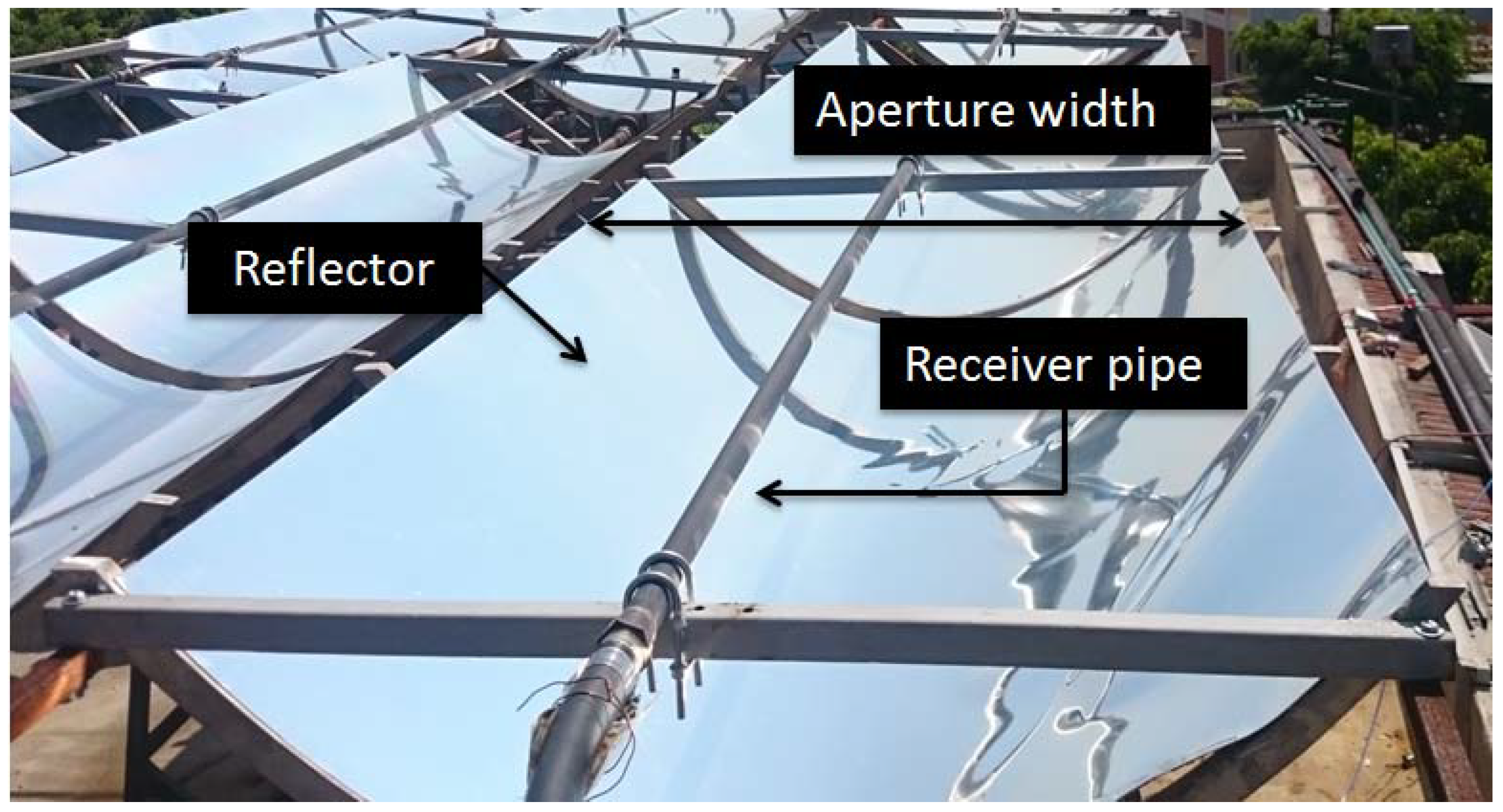
2.2. Parabolic trough Collectors

The PTC is a suitable solar concentrator device that transforms solar radiation into thermal energy by using a linear focus receiver. A heat transfer fluid flows along the receiver pipe, located in the collector focal line, and absorbs the concentrated solar energy, thus increasing its enthalpy. To ensure the localization of sun, this type of concentrator requires the one-axis solar tracking rays to fall parallel to its axis. Figure 5 shows the general scheme of the parabolic trough collector. The collector test was completed using ANSI/ASHRAE 93:2003 standard to obtain thermal efficiency. The parameters are listed in Table 1.

2.3. Shallow Geothermal Wells
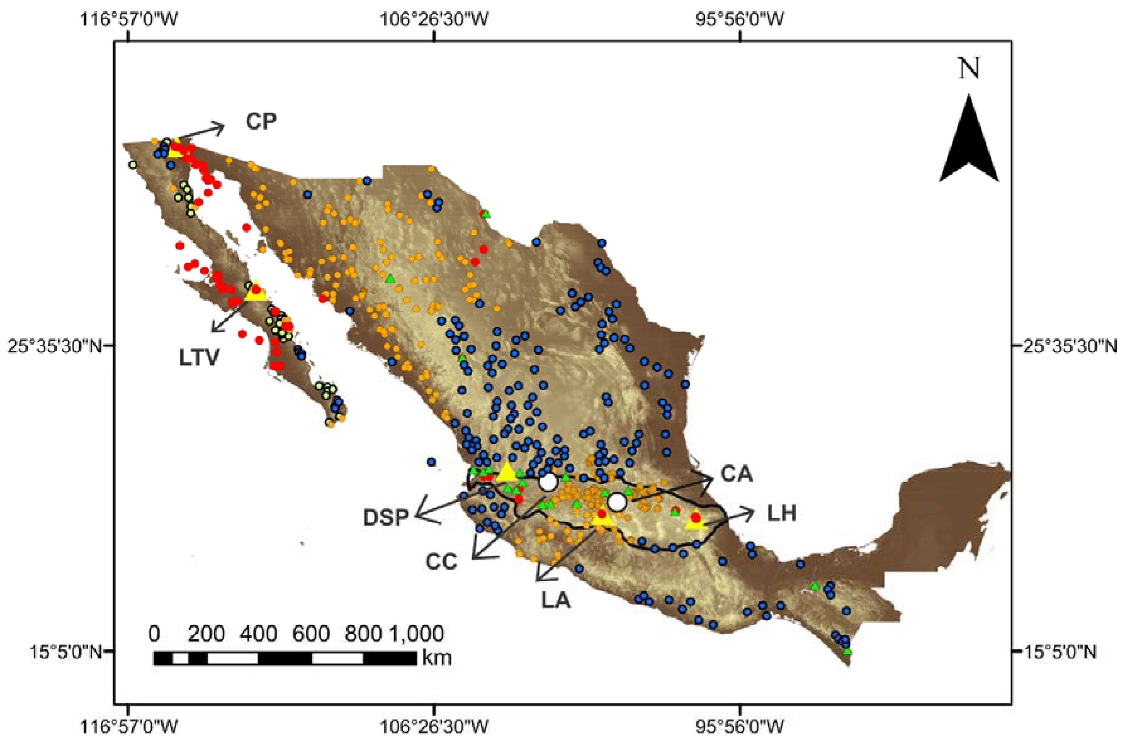
2.3.1. Study Area

La Reforma caldera is located inside the Las Tres Vírgenes volcanic complex (Figure 6) in the northern part of the state of Baja California Sur, 30 km from Santa Rosalía in the Mulegé municipality. This area has a population of 800 people who can benefit from the low and medium enthalpy for direct uses as heat pumps for air-conditioning systems. In this volcanic area, we are currently performing geophysical, geochemical, and thermal exploration studies to evaluate the geothermal potential for direct uses and power energy generation. Detailed information about the geological, geochemical, seismic, and geophysical aspects of this area have been previously described by some authors such as Garduño-Monroy [41], Verma [42], Romo [43], and Antayhua-Vera [44].

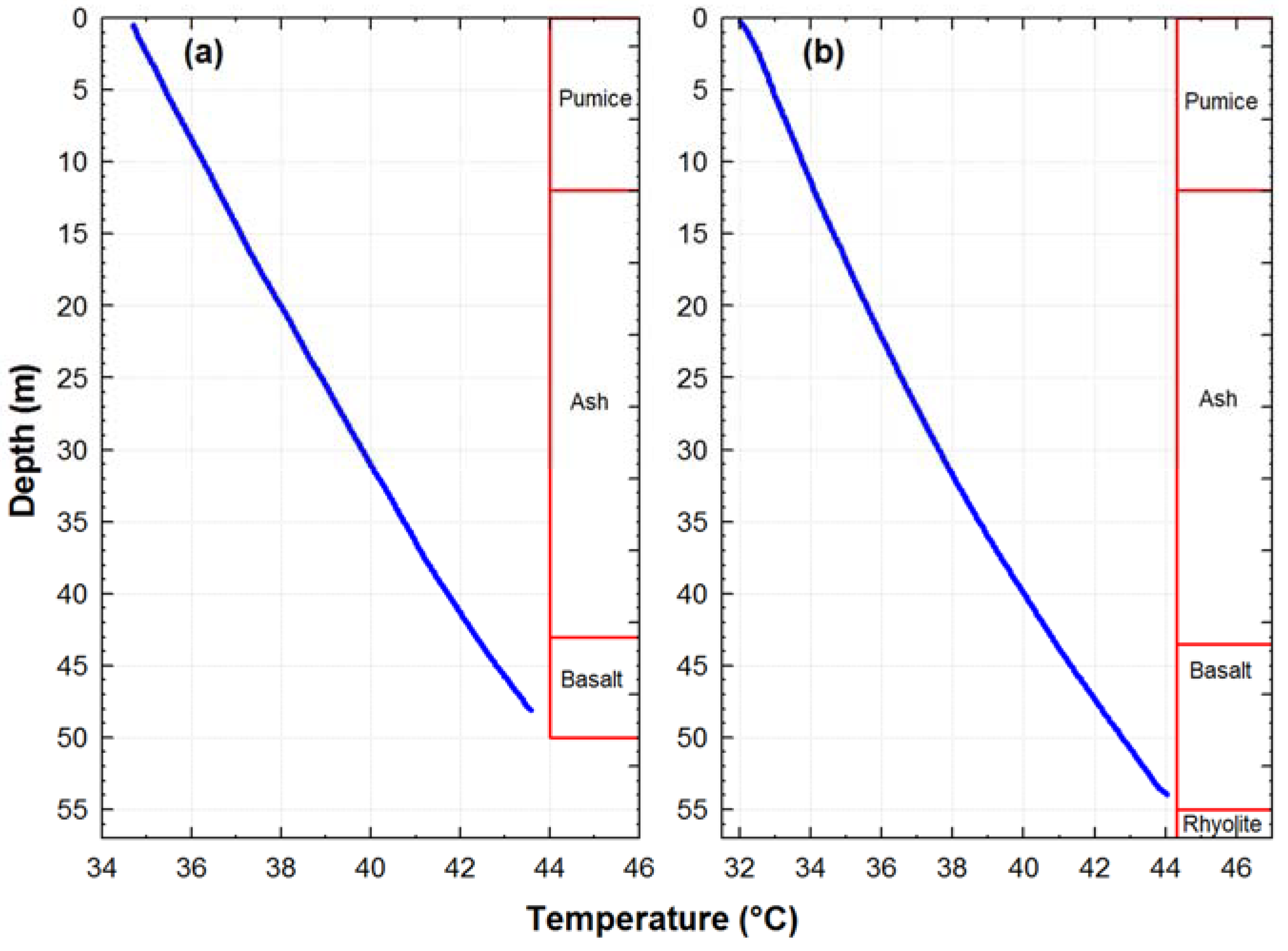
2.3.2. Drilling Wells and Log Temperatures

In 2017, two wells were drilled in the La Reforma caldera. The principal goal of this geothermal stage of exploration was to evaluate the potential geothermal energy, mainly for application in direct and industrial uses, heat pumps for district heating (air-conditioning systems), and water desalinization. The wells were drilled using 2800 HS (HT) drilling equipment with a drilling capacity of 70 m and recovery of cores. To measure the log temperature in the wells, a QL40 probe was used. This temperature measurement tool is designed for temperature profiling in geothermal projects and other high temperature applications and is compatible with the Mount Sopris Matrix geophysical logging system. This probe can register up to 170 °C, a sampling rate of two samples per second was used, and has 500 m of geophysical cable; it can register the temperature profile along this depth.
The first well has a maximum depth of 50 m and purely conductive thermal behavior. The temperature profile shows a bottom-hole temperature (BHT) of 43.5 °C at 48.0 m depth (Figure 7a). The thermal recovery (temperature vs. time) was 49.4 to 64.0 °C in 4 h (Figure 8a).
The second well has a maximum depth of 55 m and also has purely conductive thermal behavior. The temperature profile shows a BHT of 44.1 °C at a 54.0 m depth (Figure 7b). The thermal recovery was 46.4 to 64.3 °C in 4.5 h (Figure 8b). The end BHT registered from both wells was not the static formation temperature (SFT), which is the geothermal temperature before being disturbed by the drilling process.
D H T   =   ln ( Δ t   +   t c Δ t )
The SFT predicts the trough limited number of BHT measurements, registered during and after borehole drilling operations [45,46,47]. For this paper, the Horner-plot method in Equation (1) was used to estimate SFT using the thermal recovery wells (Figure 8a,b). This method indicated a linear BHT function with respect to the dimensionless Horner time ( D H T ) , as shown in Equation (2), where a linear regression computes the slope (bHM) and intercept (THM) values from Equation (1), and an extrapolation of the straight line to infinite time allows the SFT (or intercept, THM) to be determined [45,46]. The Δ t and t c values from Equation (2) correspond to the shut-in time (h) after cessation of drilling mud circulation and circulation time (h) of the drilling fluid, respectively [45,46]. The SFT for three circulation times (3, 4, and 5 h) and Δt (shut-in time) of 0.017 s were 67.2, 67.9, and 68.4 °C respectively. Therefore, the value of 62 °C for estimating the thermal gradient was suitable, since it is below the SFT.
B H T   ( Δ t )   =   T H M b H M   [ ln ( Δ t   +   t c Δ t ) ]

3. Methodology

3.1. Simulation of Single Stage Absorption Air-Conditioning System

For the analysis of the performance of the absorption cooling system, the mathematical model considered the following assumptions: (1) the cycle is in thermodynamic equilibrium; (2) steady-state conditions are assumed in the analysis; (3) the absorbent is not considered as evaporating in the temperature range assumed, so a rectifier was unnecessary; (4) the working fluid is assumed saturated when leaving the condenser and the evaporator and the solution is considered saturated when leaving the generator and the absorber; (5) the model is considered negligible as the pressure drops and heat is lost in the components and the tubing; (6) the flow through the valves is isenthalpic, and there is no solution evaporation; and (7) temperatures at the exit of the principal components T1 = T8, T2, T5, and T4 are considered, as well as the heat load in the evaporator QEV.
The physical and thermodynamic properties of NaOH-H2O were obtained from Alexey [48] and Olsson et al. [49]. The TGE is considered close in value to the outlet temperature of the well (Figure 13).
Mass and energy balance are performed for each component referred to in Figure 2.
Q ˙ GE   =   m ˙ 1 h 1   +   m ˙ 7 h 7 m ˙ 6 h 6
Q ˙ CO   =   m ˙ 1 ( h 2 h 1 )
Q ˙ EV   =   m ˙ 1 ( h 4 h 3 )
Q ˙ AB   =   m ˙ 4 h 4   +   m ˙ 8 h 8 m ˙ 5 h 5
The ratio between the heat load the evaporator and heat load in the generator is called the Coefficient of Performance (COP), plus the pump work. In this paper, COP is expressed as percentage [50].
COP   =   Q EV Q GE   +   W P

3.2. PTC Model

To determine the useful heat QU,N [W] for the array, the modification of factors such as UL, FR, and ηo had to be considered. Thus, for an array of N exact collectors operated in series, the useful heat was calculated as follows [51]:
Q U , N   =   | F R [ 1 ( 1 K ) N K ] [ G b A a η o A a C U L ( T s T a ) ] |   +  
where FR is the heat removal factor, C is the collector concentration ratio, η0 is the optical efficiency of the collector, Aa [m2] is the aperture area of the collector, Gb [W/m2] is the direct solar irradiance in the aperture plane, UL [W/m2 K] is the global heat loss coefficient assuming radiation and convection from the surface of the receptor, Ts is the temperature of the fluid inside the tank, and Ta is ambient temperature. The plus (+) sign in Equation (8) means that only positive values are considered and K is defined by:
K   =   A a F R U L m ˙ C p
where FR and UL’ are experimental factors obtained for a single collector. The modified terms ηo’ and UL’ are derived from the combination of the solar collector and interconnections given by:
η o   =   η o 1   +   ( UA ) pipe m ˙ C p
U L   =   U L ( 1 ( UA ) pipe m ˙ C p   +   2 ( UA ) pipe A r U L F R 1   +   ( UA ) pipe m ˙ C p )
where (UA)pipe [W/K] is considered the heat loss from the pipes, Ar is the receiver pipe area, m is the mass flow into the collectors, and Cp is the specific heat of the fluid that was used. The energy of the storage tank was calculated considering the useful heat, thermal load, and thermal losses to the environment. The equation that describes the system for a fully mixed storage tank is given by:
M s C ps dT s dt   =   | Q u , N |   +   ( m L ˙ C pL ) ( T s T mu ) ( U T A ) s ( T s T a )
where Ms (kg) is the mass and Cps (J/kg K) is specific heat of the working fluid in the storage tank, Ts (K) is the temperature inside the storage tank, Tmu is the temperature of the fluid that arrives from the desorber to the storage tank, and | Q u , N |   +   is the useful heat due to the storage tank heat loss.
Solar fraction is the ratio between the energy supplied by the solar system and the energy that satisfies the load demand and is given by:
f   =   Q u Q T   =   Q T Q a u x Q T
Table 2 shows the main parameters considered in the PTC design.

3.3. Seasonal Variation in Ground Temperature

Ground sources heat exchangers (GSHEs) and ground source heat pumps (GSHPs) have been used as a system for heating and cooling in buildings using shallow geothermal energy [26,27,28,29,33,34,52,53]. The design and evaluation of GSHEs require the study and analysis of the ground temperature variation [54,55,56,57,58] and heat transfer models [59,60,61,62].
The shallow variations in ground temperature are caused by seasonal fluctuations in air temperature near the surface. Jensen-Page et al. [54] mentioned that this thermal effect can reach depths between 10 and 15 m, after which the temperature becomes constant for GSHEs up to 200 m depth.
The following equation describes one-dimensional transient heat transfer in semi-infinite solid:
T t   =   α 2 T Z 2
where T is temperature (°C), t is time (s), Z is depth (m), and α is the thermal diffusivity (m2/s).
The ground temperature variation behaves like a sinusoidal wave with time; therefore, for solving Equation (14), a sinusoidal temperature model [56] was used:
T ( z , t )   =   T m   +   A z sin [ 2 π P ( t t 0 ) γ z ]   +   T z
where T ( z , t ) is the ground temperature profile at time t   (h), z is depth (m), T m is mean surface temperature (°C), A z is the annual amplitude of the ground surface temperature obtained with Equation (16), t 0 is the number of days for the ground surface temperature to be equal to T m , and T z is the geothermal gradient of 0.73 °C/m, which was calculated between the average Tsurface equal to 25 °C and BHT equal to 64 °C.
A z   =   A 0 exp γ z
where γ is the inverse of the damping depth, defined as follows:
γ   =   π α P
where P is the period of the oscillation (365 days) expressed in hours.

3.4. Convective Heat Transfer (Water Heating in the Well)

In this paper, we considered a single U-tube type heat exchanger. This heat exchanger is configured from ground-coupled heat pumps (GCHPs) that correspond to one of the subdivisions of the GSHEs or GHPs [52,53] into a bore-hole. We evaluated the convective heat transfer and estimated the maximum water temperature to the outlet, to verify if it would be possible for a water of 55–60 °C to be coupled to the PTC.
The theoretical estimation of the maximum temperature Tmax (for this study, these values represent the bulk temperature) and the convective heat transfer coefficient h of water along the depth of the well was performed using the empirical relationships for pipe and tube flow [63]. Therefore, the Tmax, which represents the energy average or mixing cup conditions, was calculated as follows [63]:
q   =   h π dL ( T W T 1   +   T 2 2 )   =   m ˙ C P ( T 2 T 1 )
where h was calculated at 260.17 W/m2 °C for fluid velocity at 5 m/s, the maximum temperature Tmax was 56.2 °C, and h was 125.47 W/m2 °C for a fluid velocity of 0.5 m/s with a Tmax of 62.9 °C. d (m), L (m), and TW (°C) of the first term represent the convective heat transfer coefficient, well diameter (pipe or tube) and well depth (total length), and wall temperatures along the depth of the well, respectively. m ˙ (kg/s), Cp, (J/kg °C), and T1 and T2 of the second term correspond to mass flow, heat capacity, and inlet and outlet temperatures of the system, respectively. In this study, T2, corresponds to Tmax. The laminar tube flow was calculated using the empirical relation proposed by Sieder and Tate [64]:
Nu d   =   1.86 ( Re d Pr d ) 1 3 ( d L ) 1 3 ( μ μ w ) 0.14
where Re d , Pr d , μ (kg/m·s) and μ w (kg/m·s) correspond to Reynold and Prandtl numbers (dimensionless) and the fluid viscosity to T1 and Tw (evaluated for the tube wall temperature), respectively. In this equation, the average convective heat transfer coefficient was determined by the function of the differences between the average of the inlet and outlet temperatures. The fluid properties were calculated by the mean bulk temperature of the fluid, except for μ w , which was assessed at the tube wall temperature [63]. The Reynold number and the additional parameters were estimated using the following equations [63]:
Re d   =   ρ C P d μ
Re d Pr d d L > 10
For the estimation of the convective heat transfer coefficient and mass flow, the following equations were applied [63]:
h   =   kNu d d
m ˙   =   ρ π d 2 4 u
where k (W/m·°C) and u (m/s) correspond to the thermal conduction and the fluid velocity, respectively. With the values obtained from Equations (18) to (23) and inserting these into Equation (18), Tmax can be estimated.
The thermal properties of water at different temperatures (both at the inlet and the tube wall) were estimated using the following polynomial regression equations. These equations were obtained from the typical data values of water at different temperatures [63].
ρ   =   999.8556   +   0.0366   T 0.0064   T 2   +   0.00002   T 3
C P   =   4225.9949 5.2960 T   +   0.2410 T 2 0.0055 T 3   +   6.2127 × 10 5 T 4 2.6538 x 10 7 T 5
μ   =   0.0018 5.8052 × 10 5 T   +   1.1457 × 10 6 T 2 1.2204 × 10 8 T 3   +   5.1839 × 10 11 T 4
k   =   0.5576   +   0.0021 T 0.0296 × 10 4 T 2   +   6.1869 × 10 8 T 3

4. Results

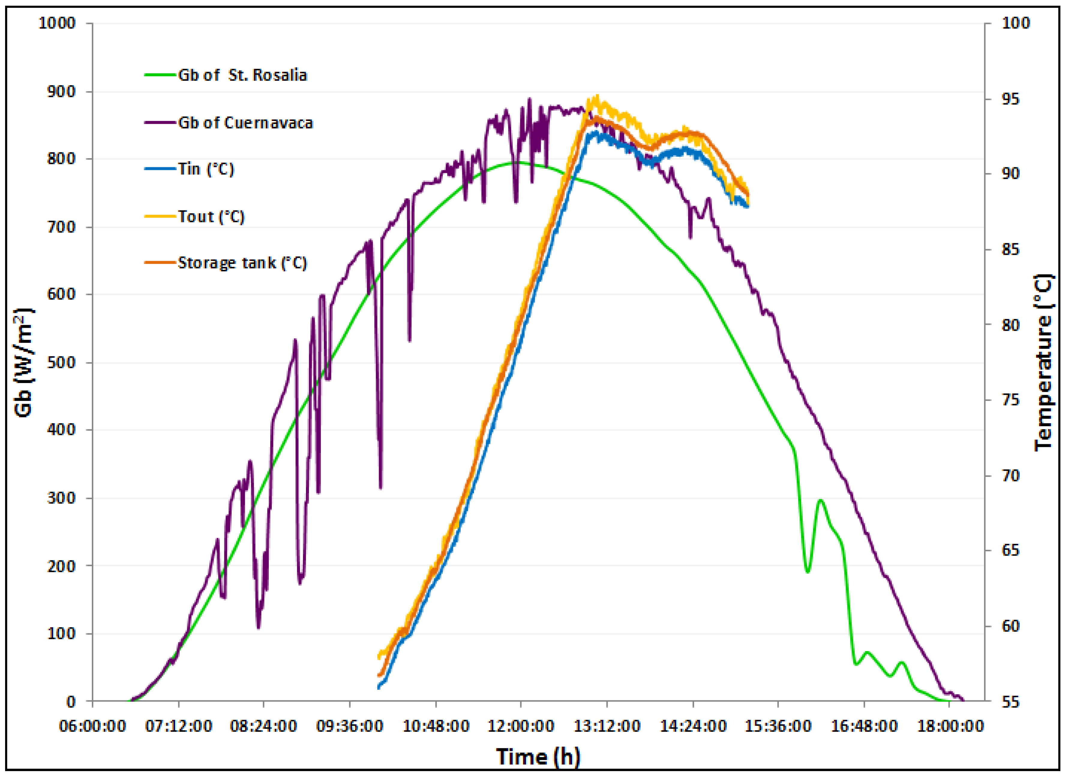
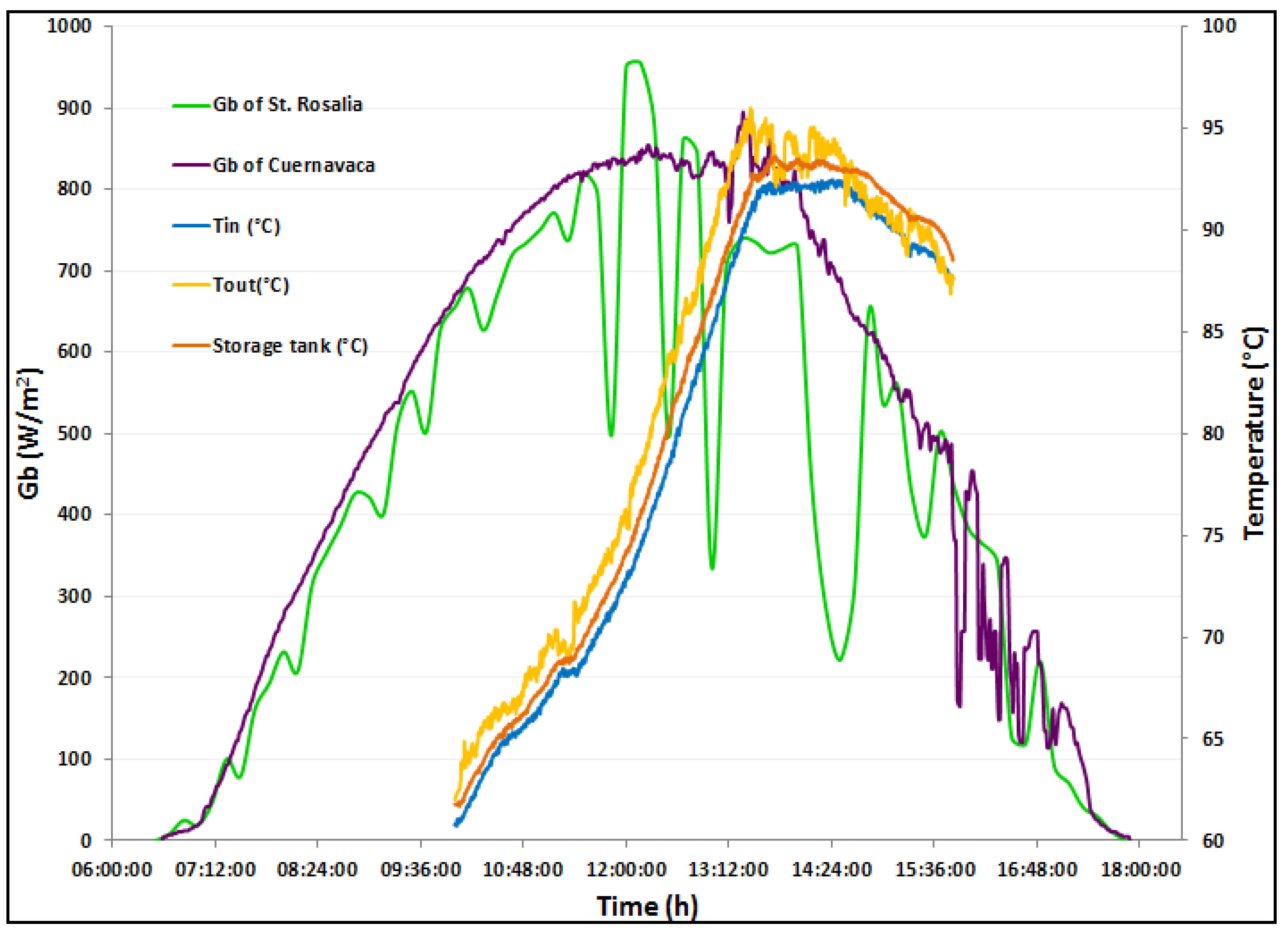
4.1. Solar-Geothermal System Evaluation

The outlet temperature from the shallow geothermal well (source) was considered according to the analysis in Figure 13. At a depth of around 40 m, the outlet temperature was 56.2 °C. Figure 9 shows the daily average soil solar radiation (Gb) recorded in Santa Rosalia and in Cuernavaca. The maximum deviation between the Gb values in Santa Rosalía and Cuernavaca was 93 W/m2 on October we, 2017. Gb from Santa Rosalía and Cuernavaca were recorded by the Santa Rosalía and CIICAp-UAEM meteorological stations, respectively. In Figure 9, the behavior of the storage tank temperature is also shown; the maximum average temperature recorded was 93.8 °C. The inlet and outlet temperatures of the storage tank increased as the Gb increased during sunny days, and decreased when the direct irradiance also decreased. This thermal energy was conserved in the storage tank.
Figure 10 shows the evaluation completed of the Gb recorded in Santa Rosalia and Cuernavaca on 25 October 2017. These databases were obtained from Santa Rosalía and CIICAp-UAEM meteorological stations, respectively. In Santa Rosalia, the presence of clouds was observed during the day. The behavior of the storage tank temperature is also shown. The maximum average temperature recorded was 92.9 °C. This thermal energy was retained in the storage tank. The inlet and outlet temperatures of the storage tank increased as the Gb increased over six hours, and decreased when the direct irradiance also decreased.

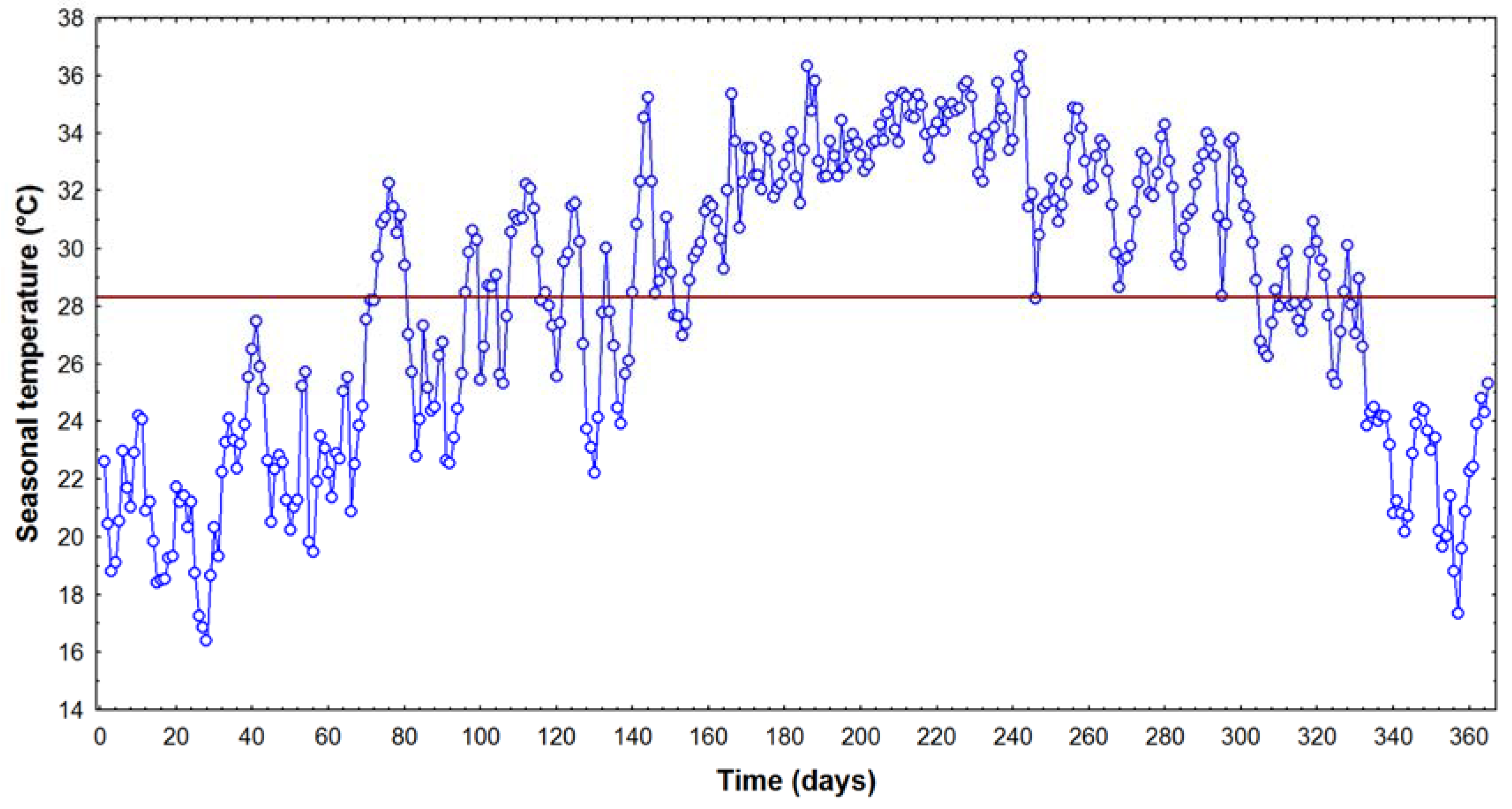
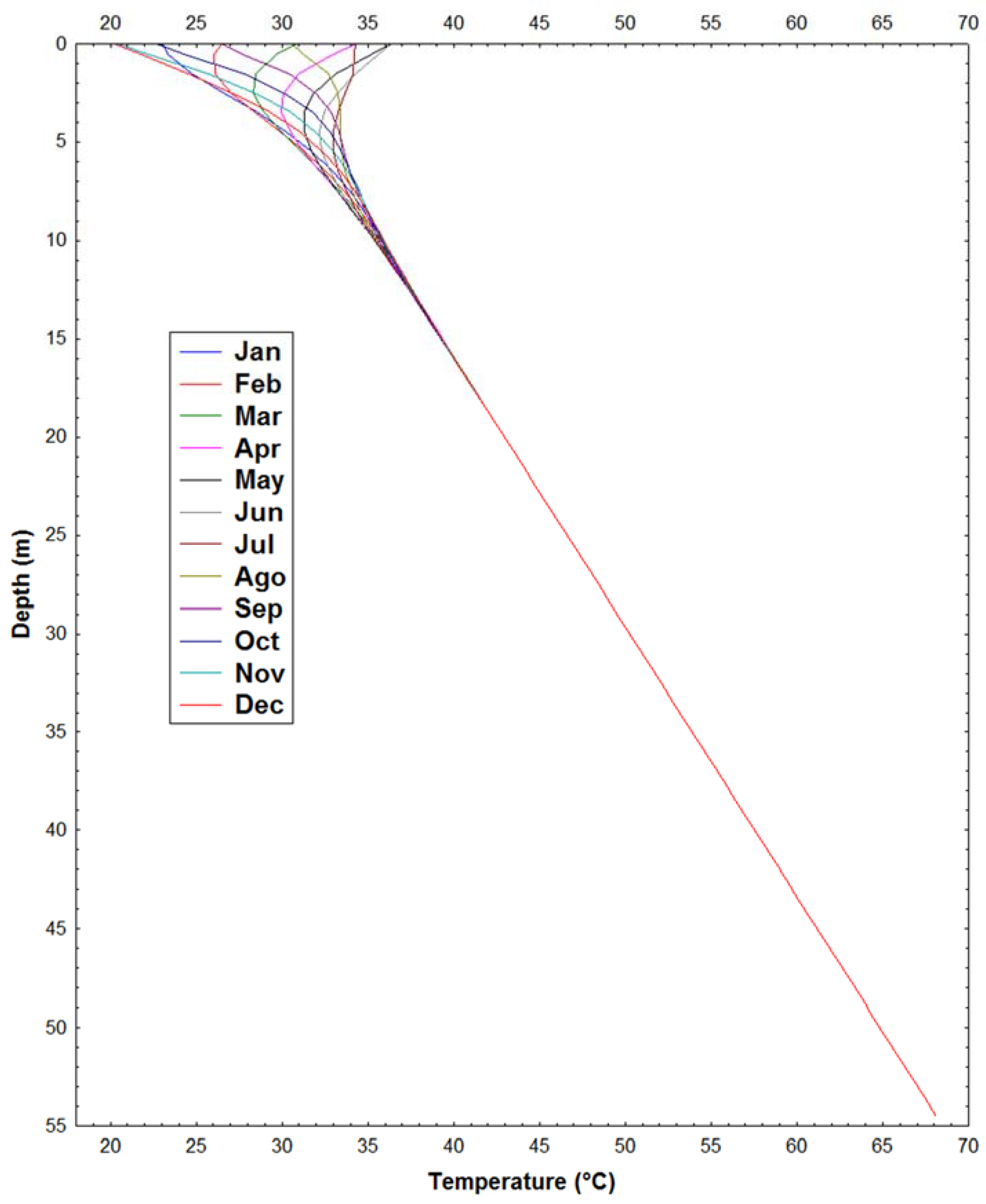
4.2. Ground Temperature Variation Results

The daily average surface air temperatures for 2017 were obtained from the Santa Rosalía meteorological station (Figure 11). This database was used to calculate the parameters in Equation (15). The amplitude of the daily temperature means was estimated as T m = 28.35 °C, A 0 = 8.31 °C. Notably, a better approach would require the application of the energy balance equation [57]. The γ (m−1) values were calculated using the thermal properties of the rocks from the second well (Figure 7a and Table 3). The period P = 8760 h (365 days), for t 0 was recorded on the 72nd day of the year as t 0 = 1728 h, and z was considered between depths of 0 and 55 m.
Substituting the parameters in Equation (15), the ground temperature variation from La Reforma caldera where the wells are located is given by:
T ( z , t )   =   28.35   +   8.31 exp γ z   sin [ 2 π 8760 ( t 1728 ) γ z ]   +   T z
Figure 12 shows the calculated results of the ground temperature variation for depths between 0 and 55 m for each month of the year (2017). The thermal effects reached depths of 15 m, after which the temperature did not vary.

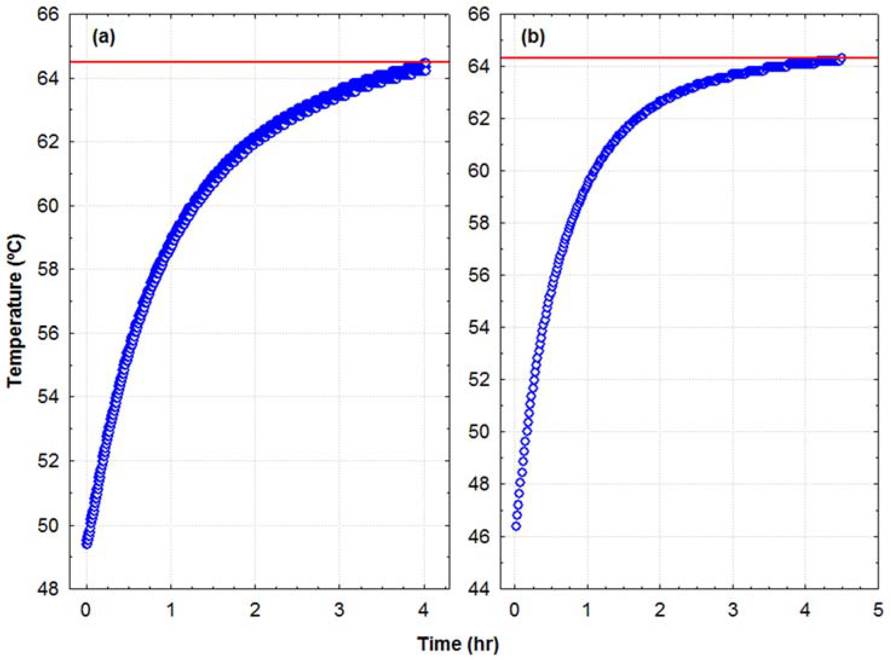
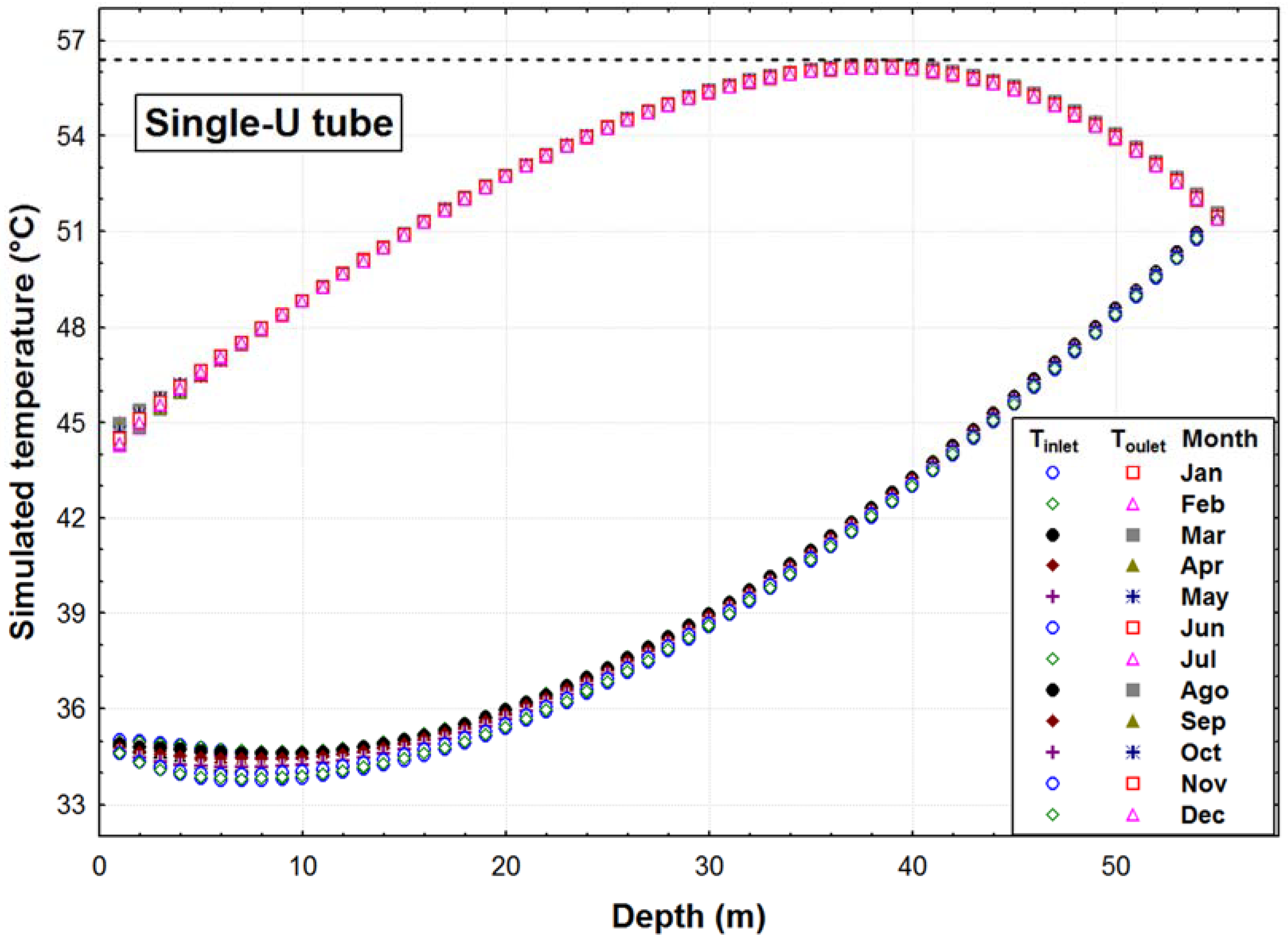
4.3 Numerical Heat Transfer

The modeling of the temperature profile was performed in a U-tube heat exchanger at the wells at the La Reforma caldera. Figure 13 shows the temperature profiles for every month of the year.
To solve Equations (18)–(27), which were programmed in Fortran, were used the following values: well depth of 55 m, a U-tube diameter of 0.07 m, inlet water temperature of 35 °C, and a Tint velocity of 10 m/s. The coefficient h, mass flow, the Reynold and Prandtl numbers, and the fluid viscosity were evaluated at Tw (ground temperature variation between 0 to 55 m).
The heat transfer results showed a slight variation in the temperature profile z from 0 to 55 m, where the Tmax was affected due to the ground temperature variations. The inlet water to the U-tube, reached a temperature of 51.6 °C at the bottom-hole (z = 55 m). When ascending to the surface, the water temperature reached 56.2 °C at 38 m. After this depth, the temperature decreased to 45 °C to the outlet. This thermal result could possibly use the Tmax value of 56.2 °C (at z = 38 m) to be coupled to the PTC.

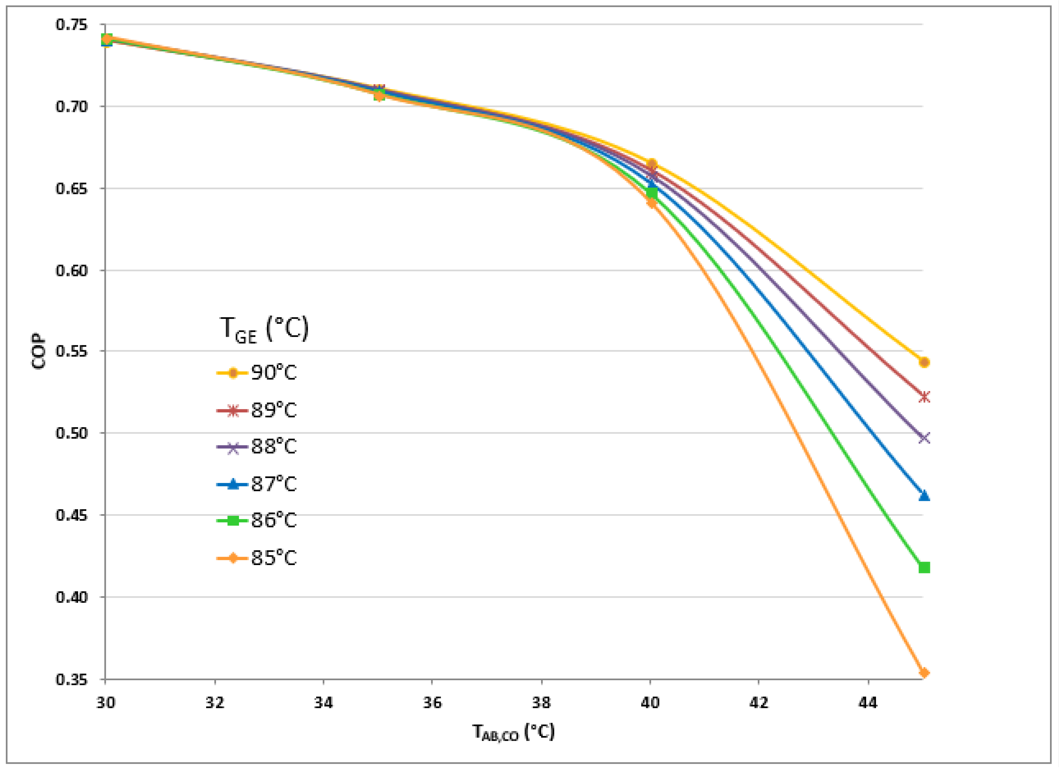
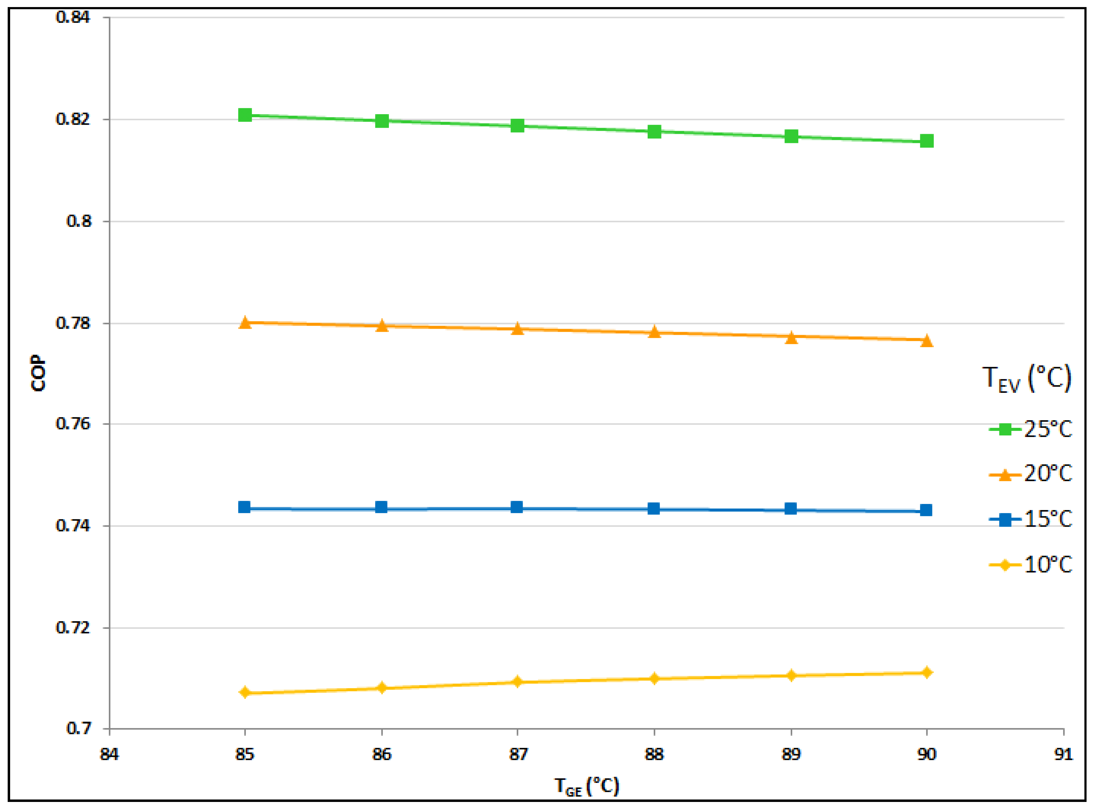
4.4. Single Stage Absorption Air-Conditioning System Evaluation

A mathematical simulation was performed to evaluate the performance of the absorption cycle. An AACS was simulated in steady state conditions with TGE = 90 °C, TCO = TAB = 35 °C, and TEV = 10 °C. Table 4 presents the simulation results for the AACS with a cooling capacity of 7.05 kW. The ambient temperature was calculated as 31.45 °C.
Figure 14 compares the COP as a function of the absorber temperature for the NaOH-H2O mixture. The following conditions were kept constant: evaporator temperature at 10 °C, absorber and condenser in the range of 30 to 45 °C, and the generator temperature in the range of 85 to 90 °C, according to the experimental evaluation of the storage tank. This figure shows the COP as a function of the generator temperature. As TGE decreases, the COP increases. The maximum COP value was calculated according to TGE = 85 °C and TCO = TAB = 30 °C. COP behavior evaluated with TGE = 90 °C had the lowest values compared to the other conditions. However, the AACS performance is also dependent on the collector temperature, and this temperature is directly related to the direct radiation Gb.
Figure 15 shows COP behavior as a function of TGE. In this plot, the condenser and absorber temperature were kept constant at 35 °C. Evaporator temperatures fluctuated in the range from 10 to 25 °C; these temperatures allow the system to achieve the AACS design conditions. COP increased when TEV increased. The maximum COP was calculated with TGE = 85 °C and TEV = 25 °C. At TEV = 10 °C, the minimum COP values were calculated. This behavior is due to the aqueous concentration, where the solution concentration strongly affects the thermophysical properties of the working fluid.
According to the results of the solar geothermal system evaluation, the storage tank can supply thermal energy at 94 °C. COP behavior was analysed considering TGE within a range of 85 to 90 °C.

5. Conclusions

This paper proposes a hybrid solar-geothermal source for air-conditioning systems. This system includes a parabolic trough solar collector field that uses a geothermal source to increase the working fluid temperature. This thermal energy can be supplied to the AACS. The goal was to bring air-conditioning to Santa Rosalia (Mulegé), Baja California Sur, Mexico.
The geothermal source, parabolic trough collector field, and absorption air-conditioning system were analysed separately. The numerical heat transfer analysis of the U-tube heat exchanger showed that water temperatures can be increased to 56.0 °C. After the heat is transferred from the geothermal source, water is pumped to the solar field. The experimental evaluation was completed using a solar field of nine parabolic trough collectors (46.1 m2). The inlet temperature of the PTC field was assumed to be below 56 °C. The experimental evaluation of the parabolic trough collector was completed in Cuernavaca on October 23 and October 25, 2017. This evaluation considered a six-hour time frame from 10:00 a.m. to 4:00 p.m. According to the results, the maximum average temperature in the storage tank on these two days was 93.8 and 92.9 °C, respectively. The numerical simulation assumed the generator temperature ranged from 85 to 90 °C in the storage tank. The absorption air-conditioning simulation used NaOH-H2O as a working mixture. The condenser and absorber temperature (TCO, TAB) were considered to be 35 °C and the evaporator temperature (TEV) was 10 °C.
These conditions were used as the ambient temperatures affect the absorber and condenser; therefore, the calculated COP of the system is lower than the design and close to 0.71. The evaporator temperature was considered 10 °C to achieve temperatures adequate for comfort.

Author Contributions

Analysis geothermal well: Efraín Gómez-Arias and Antonio González-Fernández, carried out the thermal exploration in La Reforma caldera from Las Tres Vírgenes volcanic complex and estimation of the Static Formation Temperatures. The author Efraín Gómez-Arias carried out the analysis and simulation of the ground temperatures variation from the study area. Analysis heat transfers in geothermal well: Efraín Gómez-Arias, Rosenberg J. Romero and Yuridiana Rocio Galindo-Luna carried out the evaluated the heat transfer in the U-tube heat exchanger at the wells. Analysis of parabolic-trough field: Yuridiana Rocio Galindo-Luna and Rosenberg J. Romero carried out the experimental evaluation of the solar field. Moisés Montiel-González, Jorge Díaz-Salgado and Eduardo Venegas-Reyes carried out design the parabolic-trough collector and installed the tracking system. Helene Emmi Karin Unland-Weiss and Pedro Pacheco Hernández carried out to analyzed of meteorogical datas.

Acknowledgments

The present study was supported by projects CB-167434, CeMIE-SOL-09, and CeMIE-GEO-P03, funded by SENER-CONACYT Sustainability Foundation. The authors express their gratitude to M.I. Sergio Uriel Lugo Ucan from the Institute of Renewable Energy (IER) for his help in this work. Author EGA thanks CATEDRAS-CONACYT project 2074 and the CeMIE-Geo strategic project P03 for the support and funding to carry out the study of geothermal exploration in La Reforma caldera of the Las Tres Vírgenes volcanic complex. Author EVR is thankful for the collaboration with the CEMIE-SOL-13 project. We thank Marianggy Del Carmen Gómez Ávila for help with the preparation of Figure 1, Figure 6, and Figure 11. We are also grateful to Santiago Higareda Cervera (Laboratorio de Pronóstico Metereológico—Centro de Investigación Científica y de Educación Superior de Ensenada, Baja California) and Emmanuel Alvarez R. (Comisión Nacional del Agua, the Mexican national utility company) for providing the meteorological data on the Santa Rosalía station in Baja California Norte.

Conflicts of Interest

The authors declare having no conflict of interest.

References

  1. Cabrera, F.J.; Fernández-García, A.; Silva, R.M.P.; Pérez-García, M. Use of parabolic trough solar collector for solar refrigeration and air-conditioning applications. Renew. Sustain. Energy Rev. 2013, 20, 103–118. [Google Scholar] [CrossRef]
  2. Shen, X.; Han, Y.; Zhu, S.; Zheng, J.; Li, Q.; Nong, J. Comprehensive power-supply planning for active distribution system considering cooling, heating and power load balance. J. Mod. Power Syst. Clean Energy 2015, 3, 485–493. [Google Scholar] [CrossRef]
  3. Miao, L.; Huanan, L. Analysis and assessments of combined cooling, heating and power systems in various operation modes for a building in China, Dalian. Energies 2013, 6, 2446–2467. [Google Scholar]
  4. Ghafoor, A.; Munir, A. Worldwide overview of solar thermal cooling technologies. Renew. Sustain. Energy Rev. 2015, 43, 763–774. [Google Scholar] [CrossRef]
  5. Suddiqui, M.U.; Said, S.A.M. A review of solar powered absorption system. Renew. Sustain. Energy Rev. 2015, 42, 93–115. [Google Scholar] [CrossRef]
  6. Kalogirou Soteris, A. Solar thermal collectors and applications. Prog. Energy Combust. 2014, 30, 231–295. [Google Scholar] [CrossRef]
  7. Lin, W.-M.; Tu, C.S.; Tsai, M.-T.; Lo, C.-C. Optimal energy reduction schedules for ice storage air-conditioning systems. Energies 2015, 8, 10504–10521. [Google Scholar] [CrossRef]
  8. Pavan Kumar, Y.V.; Bhimasingu, R. Renewable energy based microgrid system sizing energy management for green buildings. J. Mod. Power Syst. Clean Energy 2015, 3, 1–13. [Google Scholar] [CrossRef] [Green Version]
  9. Nchelatebe Nkwetta, D.; Smyth, M. The potential applications and advantages of powering solar air-conditioning systems using concentrator augmented solar collectors. Appl. Energy 2012, 89, 380–386. [Google Scholar] [CrossRef]
  10. Fernández-García, A.; Zarza, E.; Valenzuela, L.; Pérez, M. Parabolic-trough solar collector and their applications. Renew. Sustain. Energy Rev. 2010, 14, 1695–1721. [Google Scholar] [CrossRef]
  11. Ziuku, S.; Seyitini, L.; Mapurisa, B.; Chikodzi, D.; van Kuijk, K. Potential of concentrated solar power (CSP) in Zimbabwe. Energy Sustain. Dev. 2014, 23, 220–227. [Google Scholar] [CrossRef]
  12. Jaramillo, O.A.; Venegas-Reyes, E.; Aguilar, J.O.; Castrejón-García, R. Parabolic trough concentrator for low enthalpy processes. Renew. Energy 2013, 60, 529–539. [Google Scholar] [CrossRef]
  13. Reddy, K.S.; Kumar, K.R. Solar collector field design and viability analysis of stand-alone parabolic trough power plants for Indian conditions. Energy Sustain. Dev. 2012, 16, 456–470. [Google Scholar] [CrossRef]
  14. Rosado Hau, N.; Escalante Soberanis, M.A. Efficiency of parabolic trough collector as a water heater system in Yucatán, Mexico. J. Renew. Sustain. Energy 2011. [Google Scholar] [CrossRef]
  15. Venegas-Reyes, E.; Jaramillo, O.A.; Castrejón-García, R.; Sosa-Montemayor, F. Design, construction, and testing of a parabolic trough solar concentrator for hot water and low enthalpy steam generation. J. Renew. Sustain. Energy 2012, 4, 53–103. [Google Scholar] [CrossRef]
  16. Mazloumi, M.; Naghashzadegan, M.; Javaherdeh, K. Simulation of solar lithium bromide-water absorption cooling system with parabolic trough collector. Energy Convers. Manag. 2008, 49, 2820–2832. [Google Scholar] [CrossRef]
  17. Ghaddar, N.K.; Shihab, M.; Bdeir, F. Modeling and simulation of solar absorption system performance in Beirut. Renew. Energy 1997, 10, 539–558. [Google Scholar] [CrossRef]
  18. Baniyounes, A.M.; Rasul, M.G.; Khan, M.M.K. Assessment of solar assisted air conditioning in Central Queensland’s subtropical climate. Renew. Energy 2013, 50, 334–341. [Google Scholar] [CrossRef]
  19. Mujahid Rafique, M.; Rehman, S.; Lashing, A.; Arifi, A.N. Analysis of a solar cooling system for climatic conditions of five different cities of Saudi Arabia. Energies 2016, 9. [Google Scholar] [CrossRef]
  20. Florides, G.A.; Kalogirou, S.A.; Tassou, S.A.; Wrobel, L.C. Modelling and simulation of an absorption solar cooling system for Cyprus. Sol. Energy 2002, 72, 43–51. [Google Scholar] [CrossRef]
  21. Syed, A.; Izquierdo, M.; Rodríguez, P.; Maidment, G.; Missenden, J.; Lecuona, A.; Tozer, R. A novel experimental investigation of a solar cooling system in Madrid. Int. J. Refrig. 2005, 28, 859–871. [Google Scholar] [CrossRef]
  22. Li, Z.F.; Sumathy, K. Experimental studies on a solar powered air conditioning system with partitioned hot water storage tank. Sol. Energy 2001, 71, 285–297. [Google Scholar] [CrossRef]
  23. Zhai, X.; Li, Y.; Cheng, X.; Wang, R. Experimental investigation on a solar-powered absorption radiant cooling system. Energy Procedia 2015, 70, 552–559. [Google Scholar] [CrossRef]
  24. Bertani, R. Geothermal power generation in the world 2010–2014 updates report. Geothermics 2016, 60, 31–43. [Google Scholar] [CrossRef]
  25. Lund, J.W.; Boyd, T.L. Direct utilization of geothermal energy 2015 worldwide review. Geothermics 2016, 60, 66–93. [Google Scholar] [CrossRef]
  26. Rosiek, S.; Batlles, F.J. Shallow geothermal energy applied to a solar-assisted air-conditioning system in southern Spain: Two-year experience. Appl. Energy 2012, 100, 267–276. [Google Scholar] [CrossRef]
  27. Buonomano, A.; Calise, F.; Palombo, A.; Vicidomini, M. Energy and economic analysis of geothermal-solar trigeneration systems: A case study for a hotel building in Ischia. Appl. Energy 2015, 138, 224–241. [Google Scholar] [CrossRef]
  28. Calise, F.; Dentice dÁccadia, M.; Macaluso, A.; Piacentino, A.; Vanoli, L. Exergetic and exergoeconomic analysis of a novel hybrid solar-geothermal polygeneration system producing energy and water. Energy Convers. Manag. 2016, 115, 200–220. [Google Scholar] [CrossRef]
  29. Ahmadi Boyaghchi, F.; Chavoshi, M. Multi-criteria optimization of a micro solar-geothermal CCHP system applying water/CuO nanofluid based on exergy, exergoeconomic and exergoenvironmental concepts. Appl. Therm. Eng. 2017, 112, 660–675. [Google Scholar] [CrossRef]
  30. Romo-Jones, J.M.; Gutiérrez-Negrín, L.C.; Sánchez-Cornejo, C.; González-Alcántar, N.; García-Gutiérrez, A. 2017 Mexico Country Report; IEA-Geothermal: Paris, France, 2018. [Google Scholar]
  31. Tsai, J.-H.; Wu, C.-P.; Chang, H.-C. An investigation of geothermal energy applications and assisted air-conditioning system for energy conservation analysis. Geothermics 2014, 50, 220–226. [Google Scholar] [CrossRef]
  32. Abtullah, T.; Oguz, A. Optimization of geothermal energy aided absorption refrigeration system-GAARS: A novel ANN-based approach. Geothermics 2017, 65, 210–221. [Google Scholar]
  33. Pingye, G.; Manchao, H.; Liange, Z.; Na, Z. A geothermal recycling system for cooling and heating in deep mines. Appl. Therm. Eng. 2017, 116, 833–839. [Google Scholar]
  34. Farabi-Asl, H.; Fujii, H.; Kosukegawa, H. Cooling tests, numerical modeling and economic analysis of semi-open loop ground source heat pump system. Geothermics 2018, 71, 34–45. [Google Scholar] [CrossRef]
  35. Maya-González, R.; Guitiérrez-Negrín, L. Recursos geotérmicos para generar electricidad en México. Rev. Digit. Univ. 2007, 8, 1–13. [Google Scholar]
  36. Santoyo-Gutiérrez, E.; Torres-Alvarado, I.S. Escenario futuro de explotación de la energía geotérmica: Hacia un desarrollo sustentable. Rev. Digit. Univ. 2010, 11, 1–26. Available online: http://www.revista.unam.mx/vol.11/num10/art95/index.html (accessed on 9 April 2018).
  37. González-Ruiz, L.E.; González-Partida, E.; Garduño-Monroy, V.; Martínez, L.; Pironon, J.; Díaz-Carreño, E.H.; Yáñez-Dávila, D.; Romero-Rojas, W.; Romero-Rojas, M.C. Distribución de anomalías geotérmicas en México: Una guía útil en la prospección geotérmica. Rev. Int. Investig. Innov. Technol. 2015, 1–31. Available online: http://riiit.com.mx/apps/site/idem.php?module=Catalog&action=ViewItem&id=6216&item_id=74910 (accessed on 9 April 2018).
  38. Sigma Aldrich. Available online: https://www.sigmaaldrich.com/catalog/search?term=LiBr&interface=All&N=0&mode=match%20partialmax&lang=es&region=MX&focus=product (accessed on 9 April 2018).
  39. Domínguez Patiño, J.A.; Rodríguez Martínez, A.; Romero, R.J.; Ibarra Bahena, J.; Domínguez Patiño, M.L. Environmental impact assessment for an absorption heat transformer. OJAppS 2016, 6, 409–415. [Google Scholar] [CrossRef]
  40. Ibarra-Bahena, J.; Romero Rosenberg, J. Performance of different experimental absorber designs in absorption heat pump cycle technologies: A review. Energies 2014, 7, 751–766. [Google Scholar] [CrossRef]
  41. Garduño-Monroy, V.H.; Vargas-Ledezma, H.; Campos-Enriquez, J.O. Preliminary geologic studies of Sierra El Aguajito (Baja California, Mexico): A resurgent-type caldera. J. Volcanol. Geotherm. Res. 1993, 59, 47–58. [Google Scholar] [CrossRef]
  42. Verma, S.P.; Pandarinath, K.; Santoyo, E.; González-Partida, E.; Torres-Alvarado, I.S.; Tello-Hinojosa, E. Fluid chemistry and temperatures prior to exploitation at the Las Tres Vírgenes geothermal field, Mexico. Geothermics 2006, 35, 156–180. [Google Scholar] [CrossRef]
  43. Romo, J.J.M.; Wong-Ortega, V.; Vázquez-González, R.; Flores-Luna, C. Conductividad eléctrica y atenuación de ondas de coda en el campo geotérmico Las Tres Vírgenes en Baja California Sur. Unión Geofís. Mex. 2000, 20, 21–29. [Google Scholar]
  44. Antayhua-Vera, Y.; Lermo-Samaniego, J.; Quintanar-Robles, L.; Campos-Enríquez, O. Seismic activity and stress tensor inversion at Las Tres Vírgenes Volcanic and Geothermal Field (México). J. Volcanol. Geotherm. Res. 2015, 305, 19–29. [Google Scholar] [CrossRef]
  45. Espinoza-Ojeda, O.M.; Santoyo, E.; Andaverde, J. A new look at the statistical assessment of approximate and rigorous methods for the estimation of stabilized formation temperatures in geothermal and petroleum wells. J. Geophys. Eng. 2011, 8, 233–258. [Google Scholar] [CrossRef]
  46. Liu, C.; Li, K.; Chen, Y.; Jia, L.; Ma, D. Static formation temperature prediction based on bottom hole temperature. Energies 2016, 9, 646. [Google Scholar] [CrossRef]
  47. Kurevija, T.; Strpic, K.; Koscak-Kolin, S. Applying petroleum the pressure buildup well test procedure on thermal response test—A novel method for analyzing temperature recovery period. Energies 2018, 11, 366. [Google Scholar]
  48. Alexey, A. The equations for thermophysical properties of aqueous solutions of sodium hydroxide. In Proceedings of the 14th International Conference on the Properties of Water and Steam, Kyoto, Japan, 29 August–3 September 2004. [Google Scholar]
  49. Olsson, J.; Jernqvist, A.; Aly, G. Thermophysical properties of aqueous NaOH-H2O solutions at high concentration. Int. J. Thermophys. 1997, 18, 779–793. [Google Scholar] [CrossRef]
  50. Ibarra-Bahena, J.; Romero, R.J.; Velazquez-Avelar, L.; Valdez-Morales, C.V.; Galindo-Luna, Y.R. Evaluation of the thermodynamic effectiveness of a plate heat exchanger integrated into an experimental single stage heat transformer operating with Water/Carrol mixture. Exp. Therm. Fluid Sci. 2013, 51, 257–263. [Google Scholar] [CrossRef]
  51. Jaramillo, O.A.; Aguilar, O.; Castrejón-García, R.; Venegas-Reyes, E.; Sosa-Montemayor, F. Parabolic trough concentrators for hot water generation: Comparison of the levelized cost production. J. Renew. Sustain. Energy 2013, 5. [Google Scholar] [CrossRef]
  52. Garcia-Gutiérrez, A.; Barragan-Reyes, R.M.; Arellano-Gómez, V.M. Research and development on heat pump systems in Mexico using geothermal energy. Curr. Appl. Phys. 2010, 10, S123–S127. [Google Scholar] [CrossRef]
  53. Ioan Sarbu, I.; Sebarchievici, C. General review of ground-source heat pump systems for heating and cooling of buildings. Energy Build. 2014, 70, 441–454. [Google Scholar] [CrossRef]
  54. Jensen-Page, L.; Narsilio, G.A.; Bidarmaghz, A.; Johnston, I.W. Investigation of the effect of seasonal variation in ground temperature on thermal response tests. Renew. Energy 2018, 125, 609–619. [Google Scholar] [CrossRef]
  55. Liebel, H.T.; Huber, K.; Frengstad, B.S.; Ramstad, R.K.; Brattli, B. Temperature footprint of a thermal response test can help to reveal thermogeological information. Nor. Geol. Unders. Bull. 2011, 451, 20–31. [Google Scholar]
  56. Ozgener, O.; Ozgener, L.; Tester, J.W. A practical method to predict soil temperature variations for geothermal (ground) heat exchangers applications. Int. J. Heat Mass Transf. 2013, 62, 473–480. [Google Scholar] [CrossRef]
  57. Mihalakakou, G.; Santamouris, M.; Lewis, J.O.; Asimakopoulos, D.N. On the applications of the energy balance equation to predict ground temperature profile. Sol. Energy 1997, 60, 181–190. [Google Scholar] [CrossRef]
  58. Bandos, T.V.; Montero, Á.; Fernández de Córdoba, P.; Urchueguía, J.F. Improving parameter estimates obtained from thermal response tests: Effect of ambient air temperature variations. Geothermics 2011, 40, 136–143. [Google Scholar] [CrossRef]
  59. Li, M.; Lai, A.C.K. Review of analytical models for heat transfer by vertical ground heat exchangers (GHE’s): A perspective of time and space scales. Appl. Energy 2015, 151, 178–191. [Google Scholar] [CrossRef]
  60. Lucia, U.; Simonetti, M.; Chiesa, G.; Grisolia, G. Ground-source pump system for heating and cooling: Review and thermodynamic approach. Renew. Sustain. Energy Rev. 2017, 70, 867–874. [Google Scholar] [CrossRef]
  61. Bandos, T.V.; Montero, Á.; Fernández, E.; Santander, J.L.G.; Isidro, J.M.; Pérez, J.; Fernández de Córdoba, P.J.; Urchueguía, J.F. Finite line-source model for borehole heat exchangers: Effect of vertical temperature variation. Geothermics 2009, 38, 263–270. [Google Scholar] [CrossRef]
  62. Kim, M.; Baik, Y.J.; Park, S.R.; Chang, K.C.; Ra, H.S. Design of a high temperature production heat pump system using geothermal water at moderate temperature. Curr. Appl. Phys. 2010, 10, S117–S122. [Google Scholar] [CrossRef]
  63. Holman, J.P. Heat Transfer, 6th ed.; McGraw-Hill Book Co.: Singapore, 1986. [Google Scholar]
  64. Sieder, E.N.; Tate, C.R. Heat transfer and pressure drop pf liquids in tubes. Ind. Eng. Chem. 1936, 28, 1429–1435. [Google Scholar] [CrossRef]
  65. Eppelbaum, L.; Kutasov, I.; Pilchin, A. Lecture Notes in Earth System Sciences; Springer: Berlin, Germany, 2014. [Google Scholar]
Figure 1. Geothermal fields in Mexico: Cerro Prieto (CP); Los Azufres (LA); Los Humeros (LH), Las Tres Virgenes (LTV) and, Domo San Pedro (DSP). The Acoculco Caldera (CA) and Cerritos Colorados (CC) are geothermal fields under exploration. The red circles correspond to heat flow measurement data reported in the literature. The orange and blue circles and the green triangles represent low, medium, and high enthalpy geothermal areas, respectively.
Energies 11 01268 g001
Figure 2. Schematic diagram of the system.
Energies 11 01268 g002
Figure 3. System temperature level diagram.
Energies 11 01268 g003
Figure 4. Pressure-temperature diagram of an Absorption Air-Conditioning System (AACS).
Energies 11 01268 g004
Figure 5. Photograph of the parabolic trough collector used in this work.
Energies 11 01268 g005
Figure 6. Shows the location of the wells (W1 and W2, the circles inside the box) in La Reforma caldera from Las Tres Vírgenes volcanic complex. The triangles correspond to the volcanoes La Virgen, El Azufre, and El Viejo. The circles show the La Reforma and El Aguajito calderas. The star shows the location of the thermal spring called Agua Agria.
Energies 11 01268 g006
Figure 7. Temperature profile of wells as a function of depth. (a) For the first well, the maximum temperature was 43.5 °C at a depth of 48.0 m. (b) For the second well, the temperature was 44.1 °C at a depth of 54.0 m.
Energies 11 01268 g007
Figure 8. Thermal recovery (temperature as a function of time) at the bottom of the well. The thermal recovery (a) for the first well was 49.4–64.0 °C in 4 h, (b) and 46.4–64.3 °C in 4.5 h for the second well.
Energies 11 01268 g008
Figure 9. Behavior of daily average solar radiation (Gb) and outlet, inlet and storage tank temperatures, during 5 h, 23 October 2017.
Energies 11 01268 g009
Figure 10. Gb behavior and outlet, inlet, and storage tank temperature, over six hours on 25 October 2017.
Energies 11 01268 g010
Figure 11. Average surface air temperatures from La Reforma caldera.
Energies 11 01268 g011
Figure 12. Calculated results of the ground temperature variation for depths between 0 and 55 m for each month of 2017 from the La Reforma caldera.
Energies 11 01268 g012
Figure 13. Temperatures simulated along the U-tube heat exchanger for each month of the year (2017).
Energies 11 01268 g013
Figure 14. Coefficient of Performance (COP) as a function of the TAB for a solar AACS, for constant temperature TEV at 10 °C.
Energies 11 01268 g014
Figure 15. COP comparison as a function of the TGE for a solar absorption cooling system, for constant temperature TAB = TCO = 35 °C.
Energies 11 01268 g015
Table 1. Parameters of parabolic trough collector.
ParameterSymbolValue
LengthL4.88m
Widthw1.05m
Aperture areaAa5.124m2
Rim angleβ90degrees
Exterior diameterD0.0254m
Inner diameterd0.019m
Recommended flow rate m ˙ s 0.1l/s
Focal lengthLf0.26m
PTC thermal removal factor (ΔT/Gb)FR0.569–2.049dimensionless
Overal collector heat loss coefficientUL32.193W/m2 K
Number of PTCNo.9(units)
Table 2. Main parabolic trough collector (PTC) parameters.
ParameterValue
CountryMexico
CityCuernavaca
Latitude18°55′7′′
Longitude99°14′3′′
Required temperature90 °C
Temperature outlet80 °C
Daily required volume2735 L
Required mass flow455.8 kg/h
Design operation time10:00–16:00 h
Storage tank volume2500 L
UT of storage tank1 W/m2 K
Cp,water4196 J/kg K
Table 3. Thermal properties of drilled rocks wells [65].
RockThermal Conductivity (W/m·°C)Heat Capacity (J/kg·°C)Density (kg/m3)
Pumice (0–12 m)1.7688852360
Ash (12–43 m)1.5359202180
Basalt (43–53 m)2.2008802700
Rhyolite (53–55 m)3.52010742550
Table 4. Simulation results of the Absorption Air-Conditioning System (AACS).
StreamT (°C) m ˙ (g/s)hNaOH-H2O (kJ/kg)x (%) *
190.02.972659.560
235.02.97146.650
310.02.97146.650
410.02.972519.220
535.08.90211.3640.3
635.08.90211.3640.3
790.05.93656.6360.5
890.05.93656.6360.5
* The NaOH-H2O concentration (weight/weight).

