Article

Investigation on the Regeneration and Corrosion Characteristics of an Anodized Aluminum Plate Regenerator

1
Renewable Energy Research Group, Department of Building Services Engineering, The Hong Kong Polytechnic University, Hong Kong, China
2
Faculty of Science and Technology, Technological and Higher Education Institute of Hong Kong, Hong Kong, China
*
Author to whom correspondence should be addressed.
Energies 2018, 11(5), 1209; https://doi.org/10.3390/en11051209
Submission received: 3 April 2018 / Revised: 21 April 2018 / Accepted: 4 May 2018 / Published: 9 May 2018
(This article belongs to the Section D: Energy Storage and Application)

Abstract

:
The traditional vapor compression cooling system (VCS) has been criticized for its heavy reliance on electricity consumption and limited control ability of humidity. Compared with the VCS, the liquid desiccant cooling system (LDCS) is more efficient by handling the sensible and latent load separately. The present study investigated the regeneration and corrosion characteristics of an anodized aluminum plate regenerator for the first time. Comparative tests were conducted to present the regeneration and corrosion characteristics of the normal and anodized regenerator. The influence of internal heating on the regeneration performance was also identified. The results showed that the corrosion rate was reduced from 0.0005218 mm/year for normal aluminum to 0.000011 m/year for anodized one under the same operating conditions. However, pitting corrosion was observed at operating conditions with high solution temperature, as the anodized layer of anodized aluminum was damaged due to the high temperature. Compared with the normal aluminum regenerator, the anodized one had an average enhancement of 24% and 23.7% in terms of regeneration rate and effectiveness, respectively. It was attributed to the increment of surface energy from 26.4 mN/m for normal aluminum to 47.6 mN/m for anodized plate. Besides, it was found that, compared with adiabatic one, the internally-heated regenerator improved the regeneration rate by 6.0%~38% and the regeneration effectiveness by 6.3%~32% depending on the operating conditions. The advantage of present study is that it can guide the design of anodized aluminum regenerator for LDCS.

1. Introduction

The liquid desiccant cooling system (LDCS) has been considered as a promising alternative to the traditional vapor compression cooling system (VCS) due to its various advantages, such as being energy efficient and environmentally friendly [1,2]. Unlike the VCS, which is heavily dependent on electricity consumption, the LDCS can take advantage of low grade energy, such as solar energy, during the regeneration process of liquid desiccant. In addition, it deals with the sensible and latent load separately to avoid reheating or overcooling, which commonly occurs in VCS. Therefore, the LDCS can not only make use of renewable energy, but also meet people’s increasing pursuit of indoor thermal comfort more efficiently. As a result, it draws increasing attention worldwide in recent years [1,2,3,4]. Compared with the intense attention on the absorber [3,4], the regenerator has relatively limited research. Even though these two components have similar working principle, many differences exist in the actual operating conditions, such as the concentration of solution, working temperature, etc. Therefore, more investigation is necessary to support the design of regenerator for LDCS.
Fumo et al. [5] experimentally investigated the regeneration performance of a packed tower regenerator. They found that the desiccant temperature and solution concentration had greater impact on the regeneration performance than air flow rate and desiccant flow rate. They also built a mathematical model for the regeneration process whose results agreed well with the experimental data. Zhang et al. [6] also studied the mass transfer characteristics of a structured packing regenerator/dehumidifier. From the experimental data, they concluded that both the air flow rate and solution flow rate had a positive effect on the mass transfer coefficient. The influence of solution temperature on mass transfer coefficient was adverse due to the property of desiccant solution. Finally, a dimensionless overall mass transfer coefficient empirical correlation was developed with the prediction deviation less than 20%. Yin [7] explored the performance of a packed tower for absorber or regenerator under different operation parameters. He obtained that the average mass transfer coefficient of the regenerator was 4 g/m2·s. However, he did not show much comparative results under different working conditions. Different from the above researchers who employed lithium chloride as the liquid desiccant, calcium chloride was adopted by Bassuoni [8] to study the mass transfer performance in a structured packing tower. Four criteria were chosen to identify the influence of regeneration performance: the mass transfer coefficient, moisture removal rate, effectiveness and coefficient of performance. They found that some of these criteria showed different tendencies for dehumidification and regeneration under the same influencing parameters. Finally, the economic analysis on the LDCS was also presented. In addition to the experimental exploration of the regeneration performance of a counter flow packed bed regenerator [9], Cannistraro et al. [10] used regenerators in hospital air treatment systems, where more ventilation flow rates and considerable energy consumption were required. Liu et al. [11] also analyzed two kinds of regeneration modes: hot air and hot desiccant. She suggested that the hot desiccant mode, i.e., using regeneration heat to heat liquid desiccant rather than air, had better mass transfer performance. In their another study [12], she presented the analytical solutions for the parallel flow, counter flow and cross flow adiabatic regenerator/dehumidifier.
The aforementioned packed bed regenerator is usually operated in adiabatic conditions, i.e., there is no heat exchange between the absorber/regenerator and the outer circumstance. However, during the regeneration process, due to the difference of the partial water vapor pressure between air and liquid desiccant, water in the liquid desiccant would evaporate and absorb heat from the desiccant simultaneously. As a result, the temperature of liquid desiccant would decrease along with the regeneration and the mass transfer performance would deteriorate because of the reduction of mass transfer driving force. Moreover, due to the high packing density of packing materials, the pressure loss of air through the packed bed regenerator is quite large and more pump power for air is required. Finally, the air velocity in the packed bed regenerator should be high. Consequently, it is very likely to entrain the liquid desiccant into the air which is a great threat to the indoor air quality. To alleviate the performance deterioration under the adiabatic conditions as well as overcome the drawbacks of packed bed regenerator mentioned above, internally cooling falling film regenerator was introduced [13,14,15,16]. Compared with the adiabatic one, it has the advantages of higher efficiency, lower pressure drop and less possibility of liquid entrainment.
There are generally two types of falling film regenerator: the shell-tube type and the plate type. Compared with the former one, the plate type regenerator can be fabricated with smaller size, bigger heat and mass transfer area and lower price [17,18,19]. Therefore, in the present study, a single channel plate regenerator was chosen for detailed study. Yin et al. [13,14,15] experimentally and numerically investigated the regeneration performance of a regenerator. They deduced from the experimental results that the regeneration efficiency of internally-heated one was higher than that of adiabatic one [14]. The validated mathematical model also verified this viewpoint in Yin’s other studies [15]. Liu et al. [16] studied the regeneration performance of an internally-heated regenerator made of plastic. They concluded that the plastic internally-heated regenerator performed better than the metal ones and had the advantage of anti-corrosion as well.
The most commonly used material for the fabrication of dehumidifier/regenerator is metal [13,14,15,16]. Unfortunately, due to the special chemical properties of liquid desiccant, e.g., lithium chloride, corrosion on metal is an inevitably serious problem. Figure 1 shows some of the metal corrosion phenomenon obtained from previous studies [20] for stainless steel 304 and copper, and the present observation for normal aluminum. Even though plastic is an alternative of metals [16], the inherent low conductivity and poor wettability make it hard to take the place of metal. Therefore, it is necessary to explore other technologies related to metal anti-corrosion for regenerator fabrication.
In present study, we firstly introduced an anodized aluminum plate in the manufacture of regenerator. A single channel anodized aluminum plate regenerator was experimentally investigated with the size of 500 mm × 500 mm (Length × Width). The corrosion characteristics of normal aluminum regenerator and anodized one were identified and compared by electrochemical method. Quantitative experiments were carried out under different influencing parameters to compare the regeneration performance with and without internal heating on the purpose-built test bench. The wettability and surface energy of different plates were also investigated.

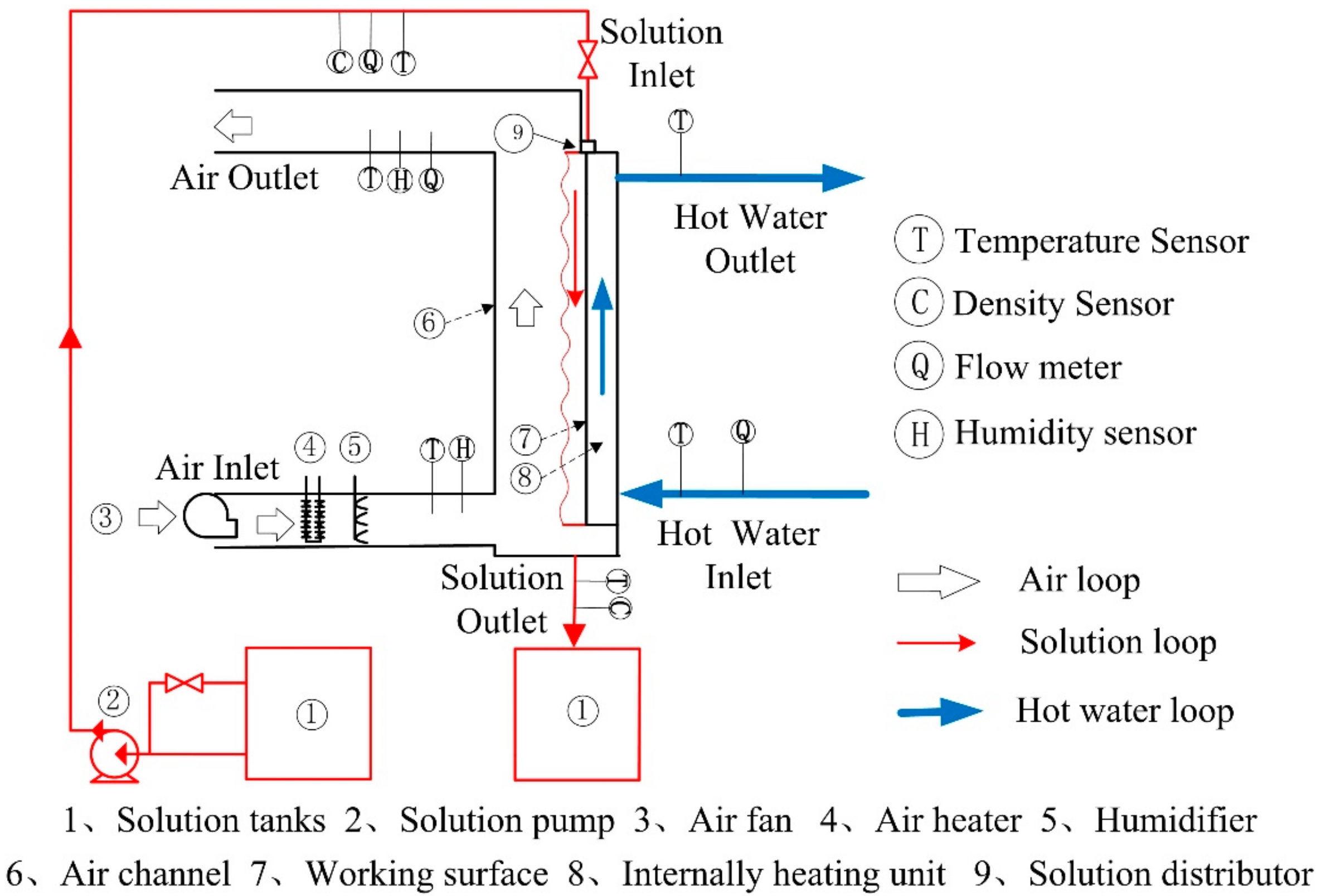
2. Experimental Apparatus

2.1. Experimental Method

To experimentally investigate the regeneration performance of normal and anodized plate regenerators, a test bench with a single channel was built, as shown in Figure 2. The system consists of three loops, namely air loop, desiccant solution loop and hot water loop. All loops are insulated by neoprene foam to prevent the heat interaction with environment.
In the air loop, outdoor air was pumped into the air loop by a fan, and the air flow rate was regulated by a valve. After that, a heater was used to adjust the air temperature to the desired point by adopting a Proportion–Integration–Differentiation (PID) controller. To identify the influence of air humidity, an electric humidifier was employed to supply different levels of moisture content by regulating the input voltage. Then, the air would flow through the single channel regenerator to contact with the falling film liquid desiccant. Because of the difference of partial water vapor pressure between solution and moist air, simultaneous heat and mass transfer proceeded in the regenerator. The inlet and outlet air temperatures and humidity were obtained by Pt-100 thermocouples and humidity sensors. Air flow rate was measured by a Pitot tube and a micro-manometer produced by TSI company. In the desiccant solution loop, the liquid solution was driven by a pump to circulate in the loop. Similarly, a heater with a PID controller was employed to adjust the solution temperature. The flow rate of solution was controlled by a by-pass valve and acquired by a turbine flow rate sensor. The concentration of LiCl solution was not measured directly but obtained through the conversion of solution density and temperature. The density and temperature of the desiccant solution were obtained firstly by a specific gravity hydrometer and a Pt-100 thermocouple. Then, the concentration was determined by both the temperature and density of desiccant solution according to the correlations provided by Conde [21]. Internal heating was introduced to improve the regeneration efficiency. Water was heated by an electric heater and then pumped into the water loop. After the heat exchange with desiccant solution in regenerator, hot water flowed back to a water tank. The flow rate and temperature of water were acquired by a turbine flow rate sensor and Pt-100 thermocouple respectively. All of the data were displayed and recorded by a data logger.

2.2. Regeneration Performance Indices

Two of the performance indices, namely regeneration rate and regeneration effectiveness, were chosen in the present study to evaluate the regeneration performance of the single channel regenerator. The definition of regeneration rate is calculated with the following Equation (1):
Δ m = m a . ( d a , o u t d a , i n )
in which m a is the mass flow rate of air. d a , o u t and d a , i n denote the outlet and inlet absolute moisture content of air respectively. As shown by Equation (1), the regeneration rate can directly show the amount of water evaporating from the liquid desiccant.
The formulation for regeneration effectiveness is expressed by Equation (2):
ξ = d a , o u t d a , i n d a , e d a , i n
in the definition of ξ , d a , e is the absolute moisture content of the processing air in the condition of equilibrium with desiccant solution at its concentration and temperature. The regeneration effectiveness is the ratio between the actual moisture change and the potential greatest moisture change.
During the data processing, the absolute air humidity is acquired from the dry bulb temperature and relative humidity of air, which can be expressed by Equation (3):
d = f ( T d r y , φ )
where T d r y is the air dry bulb temperature and φ is the relative air humidity.

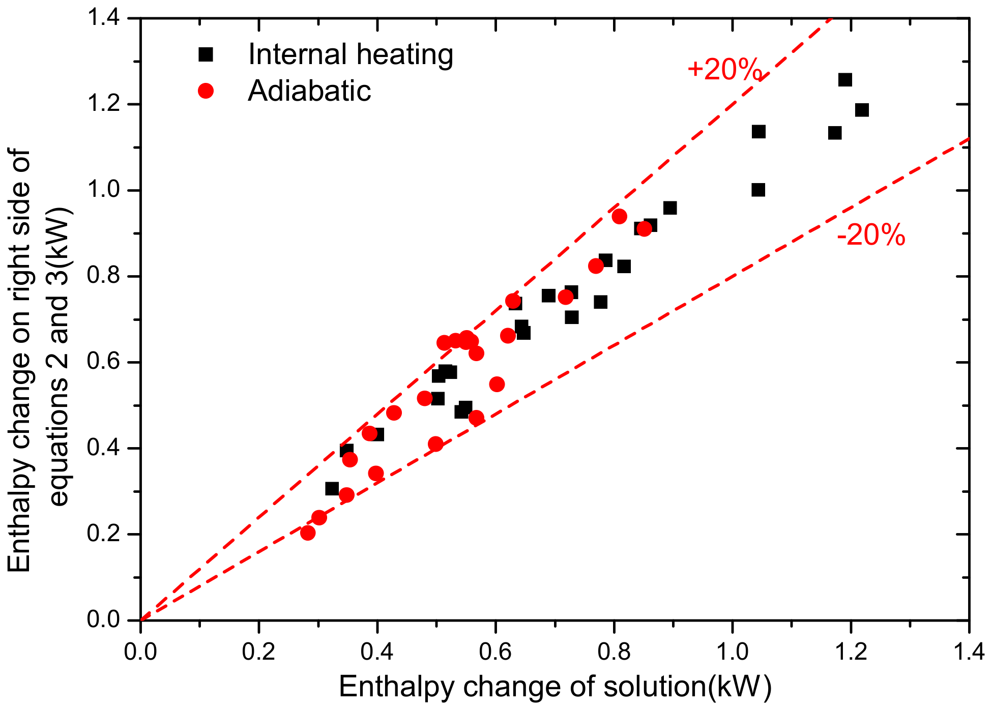
2.3. Uncertainty Analysis and Experimental Validation

All parameters during the data processing can be divided into two parts: directly measured parameters and indirectly measured ones. The uncertainties of the former group are obtained according to the accuracies of sensors, and the later ones are estimated based on the propagation of uncertainty method which is shown by Equation (4) [22]. The uncertainties for all parameters are summarized and listed in Table 1.
δ y y = ( ln f x 1 δ x 1 ) 2 + ( ln f x 2 δ x 2 ) 2 + + ( ln f x n δ x n ) ) 2
in which the indirect measured parameter is represented by y . δ x n stands for the uncertainty of the n th direct measured parameter. Equation (5) shows the relationship between the parameter of y and x i .
y = f ( x 1 , x 2 , , x i , , x n )
In the regeneration process, simultaneous heat and mass transfer occur. The conservation equations for energy and mass must be satisfied and can be expressed as follows by Equations (6)–(8):
G s ( h s , i h s , o ) = G a ( h a , o h a , i ) For   adiabatic
G s ( h s , i h s , o ) + G w ( h w , i h w , o ) = G a ( h a , o h a , i ) For   internally-heating
G a ( d a , i d a , o ) = G s X s , i ( 1 X s , o 1 X s , i )
During the regeneration experiments, all of the absolute humidity changes were found be less than 10 g/kg. In such conditions, the humidity change could be detected by humidity sensor. However, the concentration change of desiccant solution was too small to be measured accurately. Therefore, only the energy conservation equation was validated in the present study. The results are shown in Figure 3. From this figure, one can see almost all the differences of enthalpy fall into the error band of ± 20 % for both the internal heating regenerator and adiabatic one. Therefore, it is reasonable to conduct the subsequent experiments.

3. Comparison of Corrosion and Regeneration Characteristics between Normal and Anodized Aluminum Regenerator

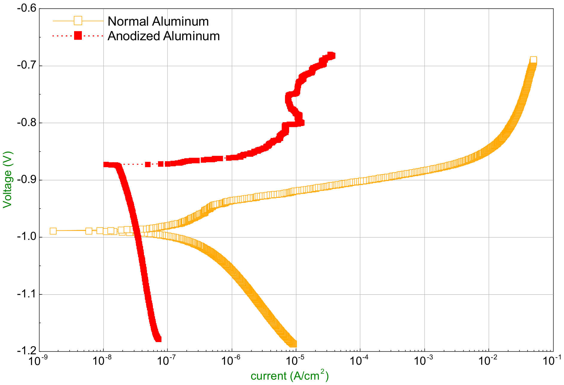
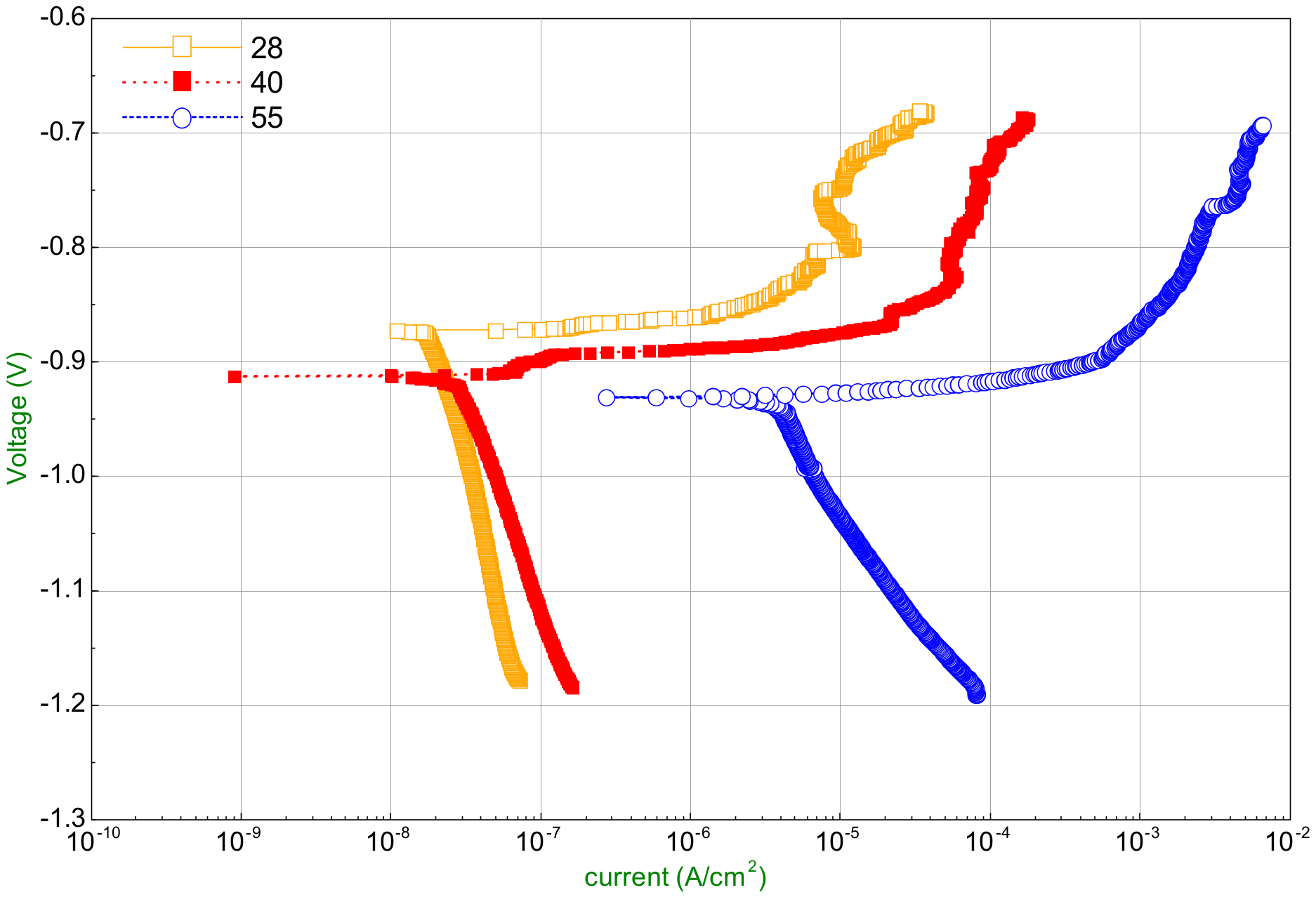
3.1. Corrosion Characteristics Identification by Electrochemical Method

The corrosion characteristics of normal and anodized aluminum plate were identified by an electrochemical station produced by Wuhan Corrtest Instruments Corp., Ltd. (Wuhan, China). The samples were firstly prepared with a 1.5 cm × 1.5 cm surface exposed outside. After surface polishing and cleaning, they were immersed into the 35% LiCl solution at the temperature of 28 °C for test. Polarization curves were obtained for each sample and shown in Figure 4. The scanning speed for polarization curve was 1 mV/s and the scanning range was −0.25 V to 0.25 V relative to the open circuit potential. The self-corrosion current and potential of sample were obtained from the curves and indicated in Table 2. The corrosion rate was calculated according to Equation (9) [23].
V c o r r = 3.27 × 10 3 I c o r r M ρ
where I c o r r is the corrosion current density. M and ρ represent the molar mass and density of sample, respectively. The corrosion rate is also shown in Table 2.
The bigger the corrosion potential is, the less possibility corrosion would occur. For corrosion current, greater current corresponds to faster corrosion [23]. Therefore, it could be concluded that the corrosion intensity of anodized aluminum decreases due to the corrosion potential changes from −0.9886 V for normal aluminum to −0.8713 V for anodized one. Consistently, the corrosion rate for anodized aluminum is smaller in terms of current density which has a decrement from 0.1579 μ A / cm 2 to 0.0261 μ A / cm 2 . Overall, the corrosion rate decreases from 0.0005218 mm/year to 0.000011 m/year by adopting the surface treatment technology of anodic oxidation.

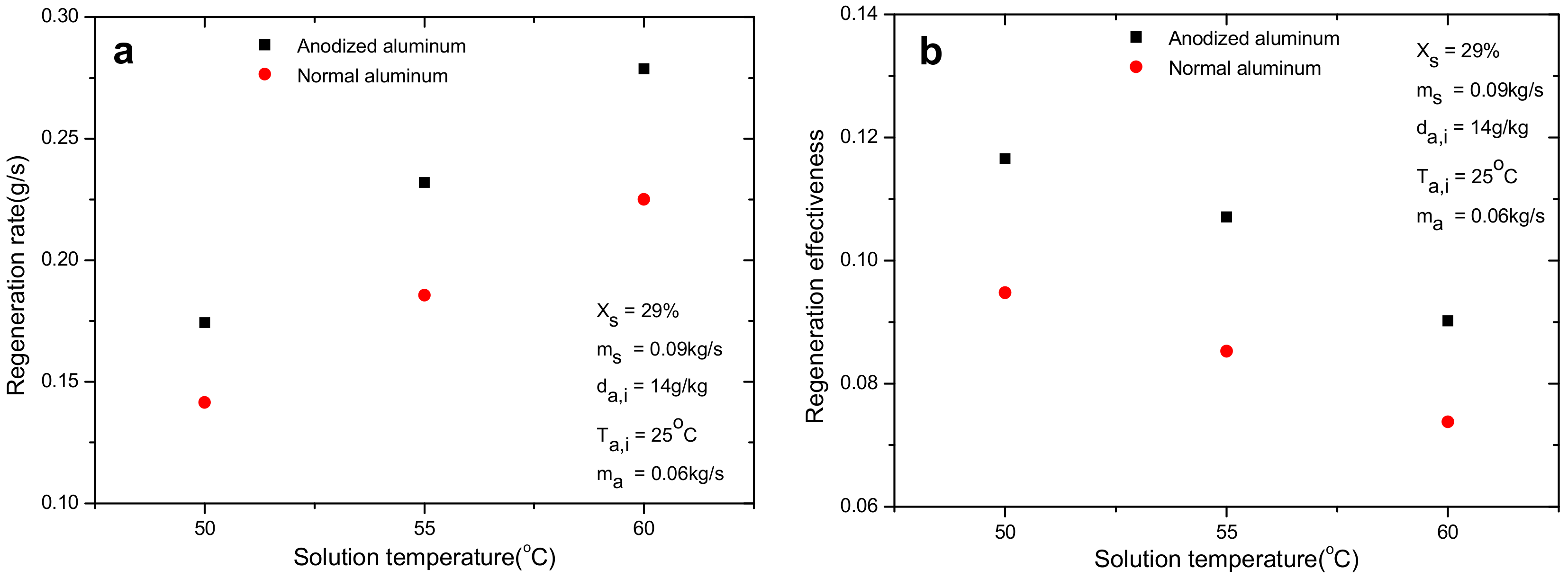
3.2. Comparison of Regeneration Performance

The regeneration performance of internal heating normal and anodized aluminum plate regenerators is compared and illustrated in Figure 5. Under the operating conditions shown in Figure 5, the regeneration rates for both regenerators have an increment trend which is cause by the growth of mass transfer driving force with the increase of solution temperature. Solution with higher temperature has bigger equivalent water vapor pressure at its surface and corresponds to greater difference of vapor pressure between liquid desiccant and air. In terms of regeneration effectiveness, it has an adverse trend compared with regeneration rate. The reason can be derived from the definition of regeneration effectiveness. Even though the numerator has an increment, the increment of the denominator is even bigger due to the change of d a , e . As a comprehensive result, the regeneration effectiveness shows a declining tendency with solution temperature. Clearly, both the regeneration rate and effectiveness of anodized regenerator show an obvious improvement compared with normal one. On average, their relative enhancements are 24% and 23.7%, respectively.

3.3. Discussion on Regeneration Performance Enhancement by Anodized Aluminum

As indicated by Figure 5, the adoption of anodized aluminum plate greatly enhances the mass transfer during regeneration compared with normal one. The reason is that the wettability of anodized aluminum plate improves significantly which is demonstrated by the infrared pictures of falling film on plates. According to our previous study, the wetting ratio rose from 71.5 to 89% with a relative increment of 24.5% [24], and larger wetting ratio means bigger contact surface between solution and air. As it was reported that the surface energy is a key factor that determines the wettability of a certain liquid on solid surface [25], the surface energy of normal and anodized aluminum plates was measured to uncover the mechanism of the wettability improvement in the paper. The two-liquid method developed by Owens [26] was employed for the purpose of surface energy measurement. The principle of this method is shown by Equation (10):
γ s = γ s D + γ s P γ L = γ L D + γ L P
where γ s and γ L represent the surface energy of solid and liquid, respectively. The superscript D and P stand for the dispersion force and polar force severally. Equation (10) can be also described as Equation (11):
γ L 1 ( 1 + cos θ 1 ) = 2 γ s D γ L 1 D + 2 γ s P γ L 1 P γ L 2 ( 1 + cos θ 2 ) = 2 γ s D γ L 2 D + 2 γ s P γ L 2 P
where θ is the contact angle of liquid on solid surface. The subscript 1 and 2 correspond to two different kinds of liquid. After selecting two kinds of liquid with known dispersion and polar force and measuring their contact angles on solid surface, the dispersion and polar force of solid surface can be acquired and so does the surface energy by adopting Equation (10).
In present study, we chose water and n-hexadecane as the two kinds of liquid and their dispersion and polar force are illustrated in Table 3. With the help of a standard contact angle goniometer (Accuracy: 0.1°) made by Rame-hart instrument Co., (Succasunna, NJ, USA), the contact angles of these two liquids on surfaces were obtained, as shown in Figure 6. After the measurement of contact angles, the surface energy of normal and anodized aluminum plates is calculated by Equations (10) and (11). The results are presented in Table 4. The surface energy changes from 26.4 mN/m to 47.6 mN/m with a nearly two-fold increment by anodizing, which is the actual reason for the enhancement of regeneration.

4. Comparison of Regeneration Performance with and without Internal Heating

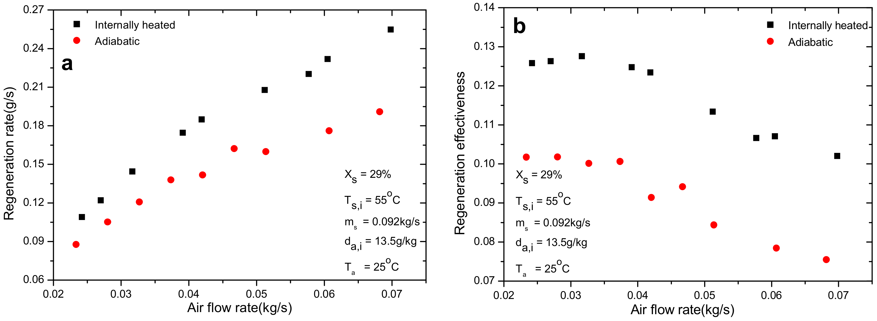
4.1. Effect of Air Flow Rate

As shown in Figure 7, for both the adiabatic and internal heating regeneration processes, the regeneration rate increases with the increase of air flow rate. On the contrary, the regeneration effectiveness decreases with the increase of air flow rate. In fact, when the air flow rate has an increment, the absolute moisture change ( Δ d ), which is defined as the absolute humidity difference between the outlet and inlet air, would reduce accordingly. It can be attributed to the decrease of contact time between air and solution. Therefore, the regeneration effectiveness would reduce when air flow rate increases, as can be seen in Figure 7b. On the other hand, even though the absolute moisture change for air has a decrement, the increment of air flow rate is bigger than such a reduction, which results in the rise of regeneration rate finally. In addition, it was found that the employment of internal heating leads to a relative improvement of 28.7% and 27.6% for regeneration rate and effectiveness on average, respectively, compared with the adiabatic one under the same operating conditions.

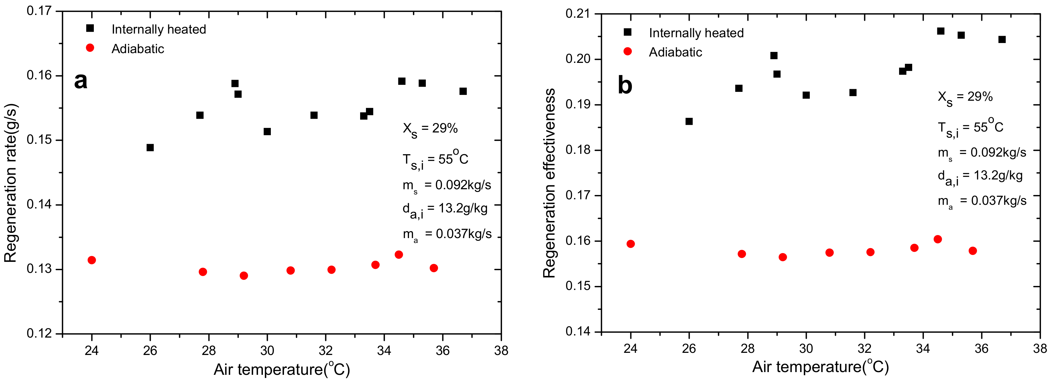
4.2. Effect of Air Inlet Dry Bulb Temperature

Figure 8 shows the regeneration performance under different air temperatures ranging from 24 °C to 37 °C. For the adiabatic one, both the regeneration rate and effectiveness keep nearly constant. However, when it comes to internal heating, both parameters show a slight increase, but the increment is tiny. The phenomenon can be explained with the mass transfer driving force between solution and air. It is the partial water vapor difference between the solution and air that drives the regeneration process, and the change of air temperature makes no difference to the driving force and so does the regeneration performance. However, the enhancement for regeneration by adopting internal heating can also be easily detected (Figure 8) because of the continual heat supply for solution from hot water. The average absolute increment for regeneration rate and effectiveness are 0.025 g/s and 4.0%, respectively.

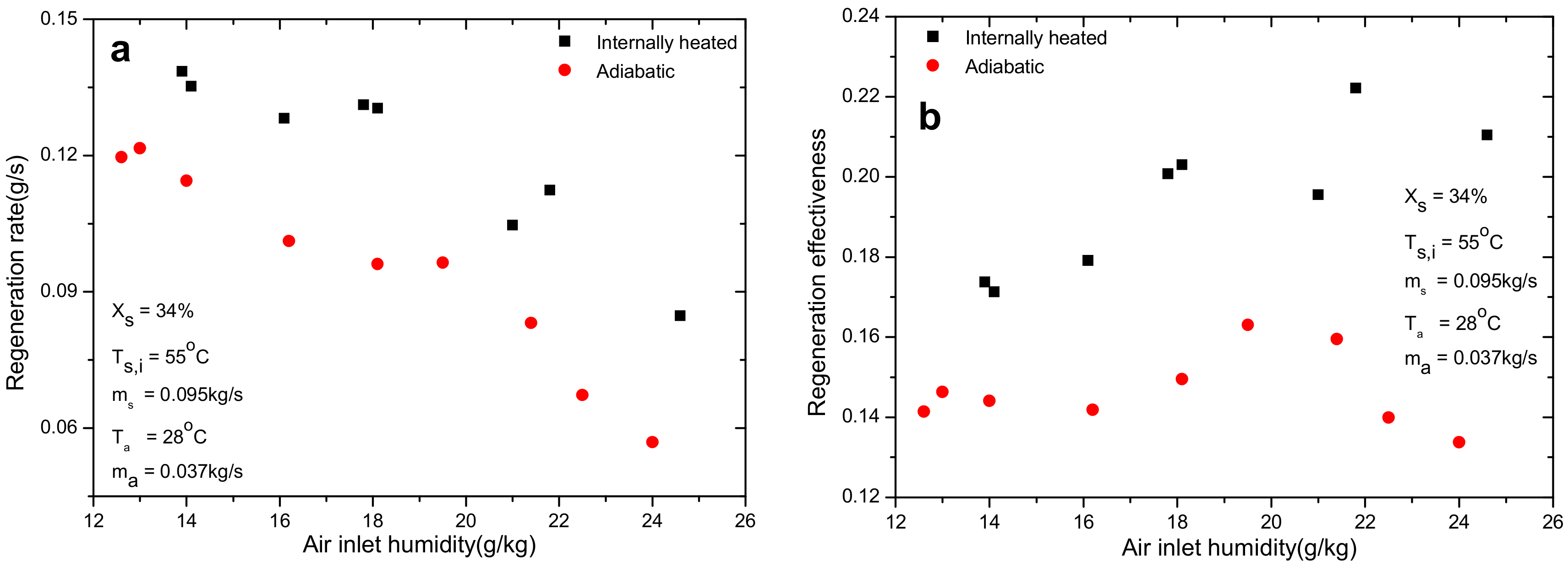
4.3. Effect of Air Inlet Absolute Humidity

The influence of air inlet humidity on mass transfer during regeneration is given in Figure 9. It can be concluded that the rise of inlet air humidity would reduce the regeneration rate due to the decline of mass transfer driving force between solution and air. Different from the regeneration rate, the regeneration effectiveness increases with the increase of air inlet humidity. According to the definition of regeneration effectiveness, it is related with both the inlet and outlet air humidity. Even though the absolute moisture change of the numerator reduces with the increase of air humidity, the reduction on denominator is even greater due to the increment of air inlet humidity. Consequently, it leads to the rise of regeneration effectiveness, as can been seen in Figure 9b. The enhancement for regeneration performance by employing anodized plate is also clearly verified in this figure.

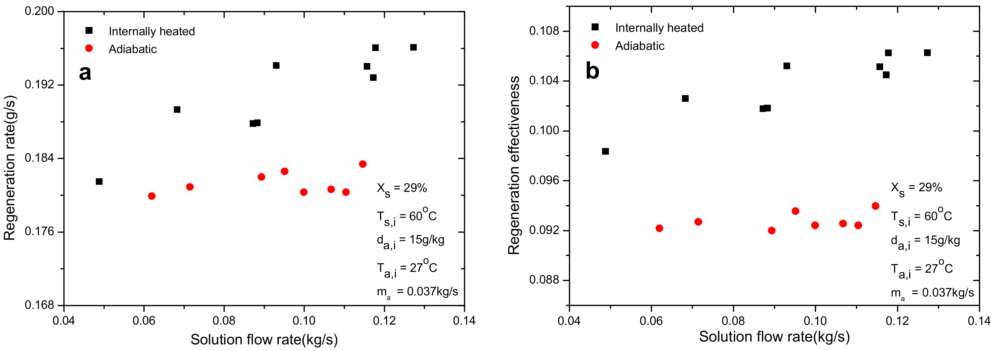
4.4. Effect of Solution Flow Rate

In Figure 10 both the regeneration rate and effectiveness for internal heating regenerator increase with the increase of solution flow rate. However, the increment was very small. The slight increment of regeneration performance is ascribed to the increment of heat transfer coefficient between solution and the wall of regenerator. Greater heat transfer coefficient can result in better internal heating performance and regeneration performance as well. However, in the adiabatic situation, the performance keeps steady when solution flow rate increases. This may be explained by the fact that the mass transfer driving force is the water vapor pressure difference between solution and air which is not related with the flow rate of solution. The average relative enhancement for regeneration rate and effectiveness are 5.96% and 12.1%, respectively.

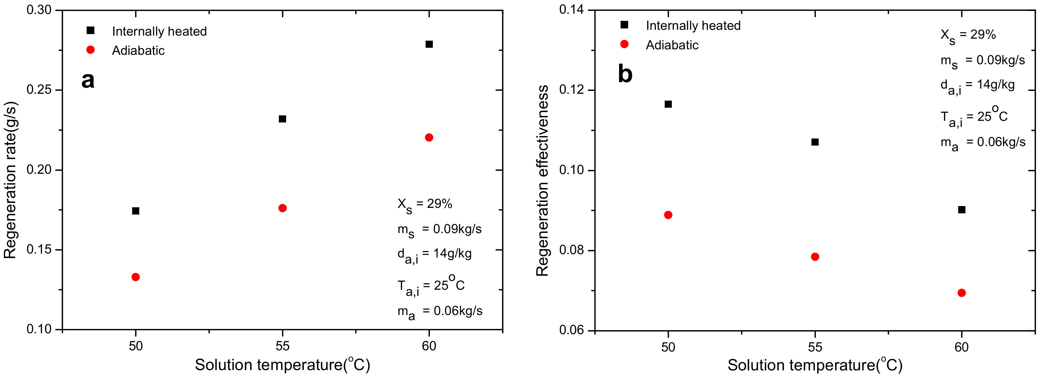
4.5. Effect of Solution Temperature

The effect of solution temperature on regeneration characteristics under certain operating conditions is indicated in Figure 11. As illustrated by this figure, the regeneration rate increases almost linearly with the growth of solution temperature. This can be easily interpreted that the rise of solution temperature increases the water vapor pressure on the solution surface directly and so does the regeneration driving force. However, the effectiveness shows an adverse trend as shown in Figure 11b. Even though the absolute moisture change of the numerator increases with solution temperature, the rise of the denominator is even bigger caused by the change of d a , e and results in the reduction of regeneration effectiveness. The advantages of internal heating in terms of regeneration rate and effectiveness are clearly revealed in this figure with an average relative increment of 29.8% and 31%, respectively.

4.6. Effect of Solution Concentration

Figure 12 reports the regeneration rate and effectiveness at solution concentration of 29%, 31%, 34% and 36%. The regeneration rate under higher concentration is smaller for both internally heated and adiabatic regenerator. Similar to the influence of solution temperature, the trend of effectiveness is opposite to that for regeneration rate at various concentrations. The reason is similar to that for concentration, thus is not repeated. The enhancement of mass transfer performance by employing internal heating decreases with the rise of solution concentration, as can been seen in Figure 11. This is caused by the bigger mass transfer driving force at lower solution concentration.

4.7. Discussion on Results and Phenomenon

In Figure 7, Figure 8, Figure 9, Figure 10, Figure 11 and Figure 12, regarding different parameters on regeneration performance for both adiabatic and internal heating anodized aluminum regenerator, distinct improvement in terms of regeneration rate and effectiveness can be clearly demonstrated. The relative enhancement of regeneration rate ranges from 6.0% to 38% at different working conditions. For regeneration effectiveness, the range is 6.3–32%. By internal heating, the solution temperature maintains at a steady level rather than decreases continually due to the evaporation of liquid water during regeneration process.
However, some interesting and noticeable phenomena were observed during the field test of regeneration. Figure 13a shows the corrosion of normal aluminum by lithium chloride solution. Many corrosion spots appeared on the surface of normal aluminum after experiments. As shown in Figure 13b, unlike normal aluminum, no corrosion spots appeared on anodized aluminum regenerator when the regeneration temperature was 50 °C. Nevertheless, when the regeneration temperature increased to 55 °C or higher, pitting corrosion occurred on the anodized aluminum regenerator, as shown in Figure 13c. The corrosion characteristics of anodized aluminum plate at the solution temperature of 28 °C, 40 °C and 55 °C were identified by the electrochemical method introduced previously. The polarization curves and corresponding results are shown in Figure 14 and Table 5. In Table 5, i the corrosion rate increases significantly from 0.000011 mm/year at solution temperature of 28 °C to 0.00217 mm/year at 55 °C. Even though the dense oxide layer covered by anodizing can resist the corrosion from liquid solution effectively at relative low operating temperature, pitting corrosion occurs and enlarges gradually at higher solution temperature which is a serious threat to the anodized aluminum regenerator. The occurrence of pitting corrosion is attributed to the damage of oxide layer [27]. To alleviate or even overcome the pitting corrosion, effective measures, such as improvement of the surface treatment technology [28], should be taken and will be conducted in our future study.

5. Conclusions

Comparative experiments were carried out on normal and anodized aluminum plate regenerators under various operating conditions. The influences of different parameters on regeneration performance were quantitatively investigated. By adopting electrochemical method, the corrosion characteristics of different regenerators were identified and compared. Some conclusions were drawn as follows:
(1)
The anodized aluminum regenerator can resist the corrosion by lithium chloride solution greatly compared with the ordinary aluminum one at relative low solution temperature. The corrosion rate decreases from 0.0005218 mm/year to 0.000011 m/year in 35% LiCl solution at 28 °C. However, when the solution temperature is higher, pitting corrosion occurs and enlarges gradually which is caused by the damage of oxide layer of anodizing.
(2)
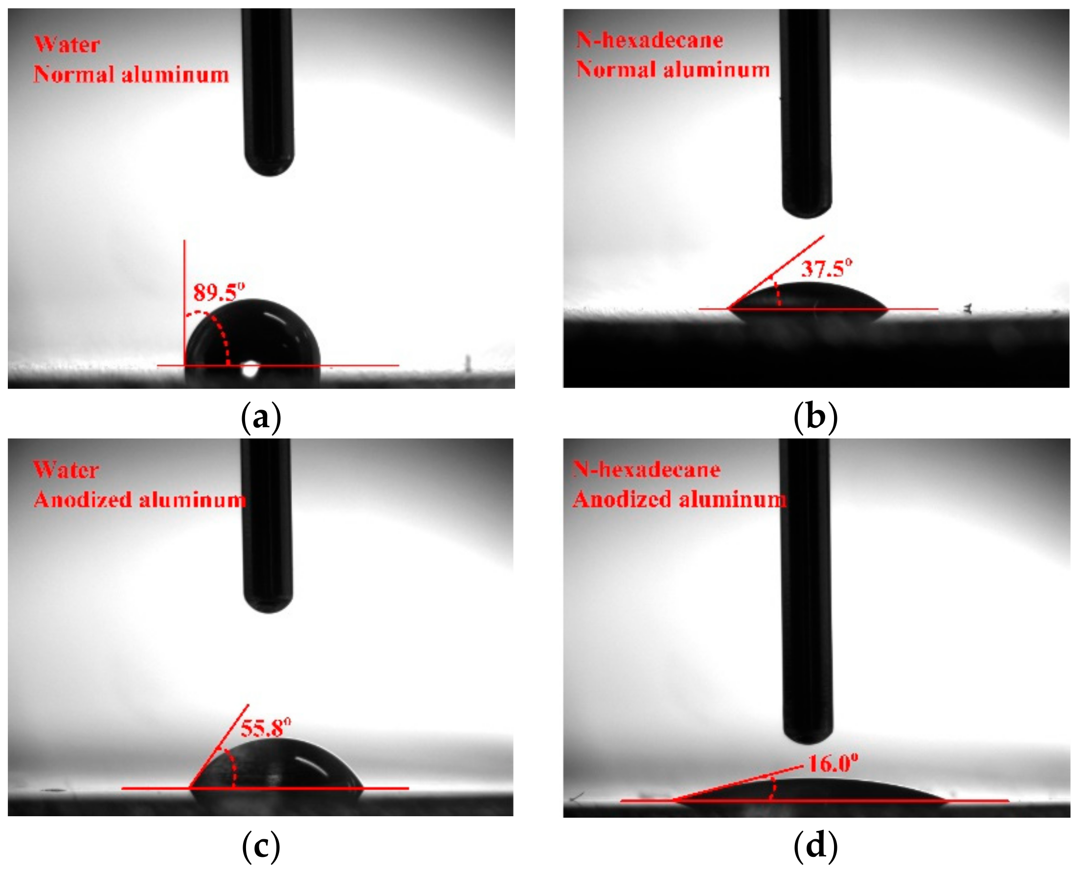
Compared with the normal aluminum plate regenerator, the anodized one improves the regeneration performance significantly in terms of regeneration rate and effectiveness by 24% and 23.7%, respectively. The enhancement is directly ascribed to the improvement of wettability of falling film on regenerator, which is caused by the enlargement of surface energy after anodizing. The surface energy increases from 26.4 mN/m for normal aluminum to 47.6 mN/m for anodized one.
(3)
Relative improvements of 6.0–38% and 6.3–32% for regeneration rate and effectiveness were detected in the internal heating regenerator compared with the adiabatic one. The introduction of internal heating greatly alleviates the decrease of solution temperature and maintains the regeneration performance at higher level.
(4)
Air inlet humidity, solution temperature and solution concentration can directly determine the mass transfer driving force and affect the regeneration performance greatly. However, other parameters, such as air inlet temperature and solution temperature, show negligible influence on regeneration performance. The regeneration rate increases with the increase of air flow rate. Nevertheless, opposite trend is observed for regeneration effectiveness.
The present experimental studies on normal and anodized aluminum single channel regenerators give guidance to the selection of regenerator material and design of compact regenerator. Nevertheless, pitting corrosion occurrence at high regeneration temperature greatly restricts the application of anodized aluminum plate regenerator. Therefore, more investigation on the mechanism and improvement of pitting corrosion, surface treatment technologies and also evaluation of possibility to use the new thermo-acoustic techniques in the refrigeration field [29] are necessary in the future work.

Author Contributions

L.L. and Y.H. conceived and designed the experiments; W.T. and L.Y. performed the experiments, analyzed the data and wrote the paper.

Acknowledgments

This project was funded by the Hong Kong Polytechnic University through Central Research Grant (PolyU 152110/14E).

Conflicts of Interest

The authors declare no conflict of interest.

Abbreviation

Nomenclature
d Absolute humidity ( g / kg ) γ Surface energy ( N / m )
E Potential ( V ) Δ Change value
G Flow rate ( kg / s )Subscripts
h Enthalpy ( kJ / kg ) a Air
I Current ( μ A / cm 2 ) D Dispersion force
L D C S Liquid desiccant cooling system c o r r corrosion
M Molar mass ( kg / mol ) d r y Dry bulb
Δ m Regeneration rate (g/s) e Equilibrium
T Temperature ( o C ) i Inlet
V Corrosion rate ( mm / Y ) L Liquid
X Concentration ( % ) o Outlet
Greek symbols P Polar force
φ Relative humidity ( % ) s Solution/solid
ρ Density ( kg / m 3 ) w Hot water

References

  1. Buker, M.S.; Riffat, S.B. Recent developments in solar assisted liquid desiccant evaporative cooling technology—A review. Energy Build. 2015, 96, 95–108. [Google Scholar] [CrossRef]
  2. Rafique, M.M.; Gandhidasan, P.; Bahaidarah, H.M.S. Liquid desiccant materials and dehumidifiers—A review. Renew. Sustain. Energy Rev. 2016, 56, 179–195. [Google Scholar] [CrossRef]
  3. Abdel-Salam, A.H.; Simonson, C.J. State-of-the-art in liquid desiccant air conditioning equipment and systems. Renew. Sustain. Energy Rev. 2016, 58, 1152–1183. [Google Scholar] [CrossRef]
  4. Ahmed, M.H.; Kattab, N.M.; Fouad, M. Evaluation and optimization of solar desiccant wheel performance. Renew. Energy 2005, 30, 305–325. [Google Scholar] [CrossRef]
  5. Fumo, N.; Goswami, D.Y. Study of an aqueous lithium chloride desiccant system: Air dehumidification and desiccant regeneration. Sol. Energy 2002, 72, 351–361. [Google Scholar] [CrossRef]
  6. Zhang, L.; Hihara, E.; Matsuoka, F.; Dang, C. Experimental analysis of mass transfer in adiabatic structured packing dehumidifier/regenerator with liquid desiccant. Int. J. Heat Mass Transf. 2010, 53, 2856–2863. [Google Scholar] [CrossRef]
  7. Yin, Y.; Zhang, X.; Chen, Z. Experimental study on dehumidifier and regenerator of liquid desiccant cooling air conditioning system. Build. Environ. 2007, 42, 2505–2511. [Google Scholar] [CrossRef]
  8. Bassuoni, M.M. An experimental study of structured packing dehumidifier/regenerator operating with liquid desiccant. Energy 2011, 36, 2628–2638. [Google Scholar] [CrossRef]
  9. Liu, X.H.; Jiang, Y.; Chang, X.M.; Yi, X.Q. Experimental investigation of the heat and mass transfer between air and liquid desiccant in a cross-flow regenerator. Renew. Energy 2007, 32, 1623–1636. [Google Scholar] [CrossRef]
  10. Cannistraro, M.; Galvagno, A.; Trovato, G. Analysis and measures for energy savings in operating theaters. Int. J. Heat Technol. 2017, 35, S422–S448. [Google Scholar] [CrossRef]
  11. Liu, X.H.; Jiang, Y.; Yi, X.Q. Effect of regeneration mode on the performance of liquid desiccant packed bed regenerator. Renew. Energy 2009, 34, 209–216. [Google Scholar] [CrossRef]
  12. Liu, X.; Jiang, Y.; Xia, J.; Chang, X. Analytical solutions of coupled heat and mass transfer processes in liquid desiccant air dehumidifier/regenerator. Energy Convers. Manag. 2007, 48, 2221–2232. [Google Scholar] [CrossRef]
  13. Yin, Y.; Zhang, X.; Wang, G.; Luo, L. Experimental study on a new internally cooled/heated dehumidifier/regenerator of liquid desiccant systems. Int. J. Refrig. 2008, 31, 857–866. [Google Scholar] [CrossRef]
  14. Yin, Y.; Zhang, X.; Peng, D.; Li, X. Model validation and case study on internally cooled/heated dehumidifier/regenerator of liquid desiccant systems. Int. J. Therm. Sci. 2009, 48, 1664–1671. [Google Scholar] [CrossRef]
  15. Yin, Y.; Zhang, X. Comparative study on internally heated and adiabatic regenerators in liquid desiccant air conditioning system. Build. Environ. 2010, 45, 1799–1807. [Google Scholar] [CrossRef]
  16. Liu, J.; Zhang, T.; Liu, X.; Jiang, J. Experimental analysis of an internally-cooled/heated liquid desiccant dehumidifier/regenerator made of thermally conductive plastic. Energy Build. 2015, 99, 75–86. [Google Scholar] [CrossRef]
  17. Flamensbeck, M.; Summerer, F.; Riesch, P.; Ziegler, F.; Alefeld, G. A cost effective absorption chiller with plate heat exchangers using water and hydroxides. Appl. Therm. Eng. 1998, 18, 413–425. [Google Scholar] [CrossRef]
  18. Estiot, E.; Natzer, S.; Behr, C.; Eichel, P.; Kren, C.; Schweigler, C. Warmetauscherentwicklung fur Kompakte Wasser/LIBR-Absorptions-Kalteanlagen; DKV Tagungsbericht: Dresden, Germany, 2006; Volume 33, pp. 153–166. [Google Scholar]
  19. Kim, D.S.; Ferreira, C.A.I. Flow patterns and heat and mass transfer coefficients of low Reynolds number falling film flows on vertical plates: Effects of a wire screen and an additive. Int. J. Refrig. 2009, 32, 138–149. [Google Scholar] [CrossRef]
  20. Luo, Y.; Shao, S.; Xu, H.; Tian, C.; Yang, H. Experimental and theoretical research of a fin-tube type internally-cooled liquid desiccant dehumidifier. Appl. Energy 2014, 133, 127–134. [Google Scholar] [CrossRef]
  21. Wen, T.; Lu, L.; Dong, C.; Luo, Y. Investigation on the regeneration performance of liquid desiccant by adding surfactant PVP-K30. Int. J. Heat Mass Transf. 2018, 123, 445–454. [Google Scholar] [CrossRef]
  22. Coleman, H.W.; Steele, W.G. Experimentation, Validation, and Uncertainty Analysis for Engineers; John Wiley & Sons: Hoboken, NJ, USA, 2009. [Google Scholar]
  23. Roberge, P. Handbook of Corrosion Engineering 2/E; McGraw Hill Professional: New York, NY, USA, 2012. [Google Scholar]
  24. Wen, T.; Lu, L.; Dong, C.; Luo, Y. Development and experimental study of a novel plate dehumidifier made of anodized aluminum. Energy 2018, 144, 169–177. [Google Scholar] [CrossRef]
  25. Adamson, A.W.; Gast, A.P. Physical Chemistry of Surfaces; Interscience: Geneva, Switzerland, 1967. [Google Scholar]
  26. Owens, D.K.; Wendt, R.C. Estimation of the surface free energy of polymers. J. Appl. Polym. Sci. 1969, 13, 1741–1747. [Google Scholar] [CrossRef]
  27. Wang, B.; Zhang, L.; Su, Y.; Mou, X.; Xiao, Y.; Liu, J. Investigation on the corrosion behavior of aluminum alloys 3A21 and 7A09 in chloride aqueous solution. Mater. Des. 2013, 50, 15–21. [Google Scholar] [CrossRef]
  28. Liu, T.; Zhang, F.; Xue, C.; Li, L.; Yin, Y. Structure stability and corrosion resistance of nano-TiO2 coatings on aluminum in seawater by a vacuum dip-coating method. Surf. Coat. Technol. 2010, 205, 2335–2339. [Google Scholar] [CrossRef]
  29. Piccolo, A.; Siclari, R.; Rando, F.; Cannistraro, M. Comparative performance of thermoacoustic heat exchangers with different pore geometries in oscillatory flow. implementation of experimental techniques. Appl. Sci. 2017, 7, 784. [Google Scholar] [CrossRef]
Figure 1. Corrosion phenomenon of liquid desiccant on metals: (a) stainless steel (b) aluminum.
Energies 11 01209 g001
Figure 2. Schematic diagram of the test bench.
Energies 11 01209 g002
Figure 3. Results of energy balance validation.
Energies 11 01209 g003
Figure 4. Polarization curve of normal and anodized aluminum plates.
Energies 11 01209 g004
Figure 5. Comparison of regeneration performance between different regenerators: (a) regeneration rate (b) regeneration effectiveness.
Energies 11 01209 g005
Figure 6. Contact angles of tested liquid on normal and anodized aluminum surfaces. (a) Contact angle of water on normal Al; (b) Contact angle of n-hexadecane on normal Al; (c) Contact angle of water on anodized Al; (d) Contact angle of n-hexadecane on anodized Al.
Energies 11 01209 g006
Figure 7. Effect of air flow rate on regeneration performance: (a) regeneration rate; (b) regeneration effectiveness.
Energies 11 01209 g007
Figure 8. Effect of air inlet dry bulb temperature on regeneration performance: (a) regeneration rate; (b) regeneration effectiveness.
Energies 11 01209 g008
Figure 9. Effect of air inlet humidity on regeneration performance: (a) regeneration rate; (b) regeneration effectiveness.
Energies 11 01209 g009
Figure 10. Effect of solution flow rate on regeneration performance: (a) regeneration rate; (b) regeneration effectiveness.
Energies 11 01209 g010
Figure 11. Effect of solution temperature on regeneration performance: (a) regeneration rate; (b) regeneration effectiveness.
Energies 11 01209 g011
Figure 12. Effect of solution concentration on regeneration performance: (a) regeneration rate; (b) regeneration effectiveness.
Energies 11 01209 g012
Figure 13. Surface conditions of normal and anodized aluminum regenerator after experiments. (a) Corrosion on normal Al; (b) Surface condition after regeneration experiments of anodized Al; (c) Pitting corrosion on anodized Al under high solution temperature.
Energies 11 01209 g013
Figure 14. Corrosion characteristics of anodized aluminum plate under different solution temperatures.
Energies 11 01209 g014
Table 1. Summary of parameters’ uncertainties.
ParameterUncertaintyParameterUncertainty
Temperature/ T ± 0.1   K Hot water flow rate/ G w ± 3 %
Solution flow rate/ G s ± 3 % Solution concentration/ X s 0.2 %
Solution density/ ρ s ± 1   kg Air absolute humidity/ d 2.5 %
Air flow rate/ G a ± 2.2 % Regenerator rate/ Δ m 3.5 %
Air relative humidity/ φ ± 2.5 % Regenerator effectiveness/ ξ 5.8 %
Table 2. Corrosion parameters of stainless steel in different solutions.
Solution E c o r r   ( V ) I c o r r   ( μ A / cm 2 ) V c o r r   ( mm / Y )
Normal Aluminum−0.98860.15970.0005218
Anodized Aluminum−0.87130.02610.000011
Table 3. Parameters of the tested liquid for surface energy measurement.
Liquid γ L P γ L D γ L
water51 mN/m21.8 mN/m72.8 mN/m
n-hexadecane0 mN/m27.6 mN/m27.6 mN/m
Table 4. Results for surface energy measurement.
SurfaceWater Contact Anglen-Hexadecane Contact AngleSurface Energy
Normal Al89.5°37.5°26.4 mN/m
Anodized Al55.8°16.0°47.6 mN/m
Table 5. Corrosion parameters of anodized aluminum in solution with different temperatures.
Temperature/°C E c o r r   ( V ) I c o r r   ( μ A / cm 2 ) V c o r r   ( mm / Y )
28−0.87130.02610.000011
40−0.91270.05480.000179
55−0.93145.190.00217

