Electric Vehicle Fast-Charging Station Unified Modeling and Stability Analysis in the dq Frame


Abstract
:1. Introduction
2. EV Fast-Charging Station Interaction System Dynamic Model
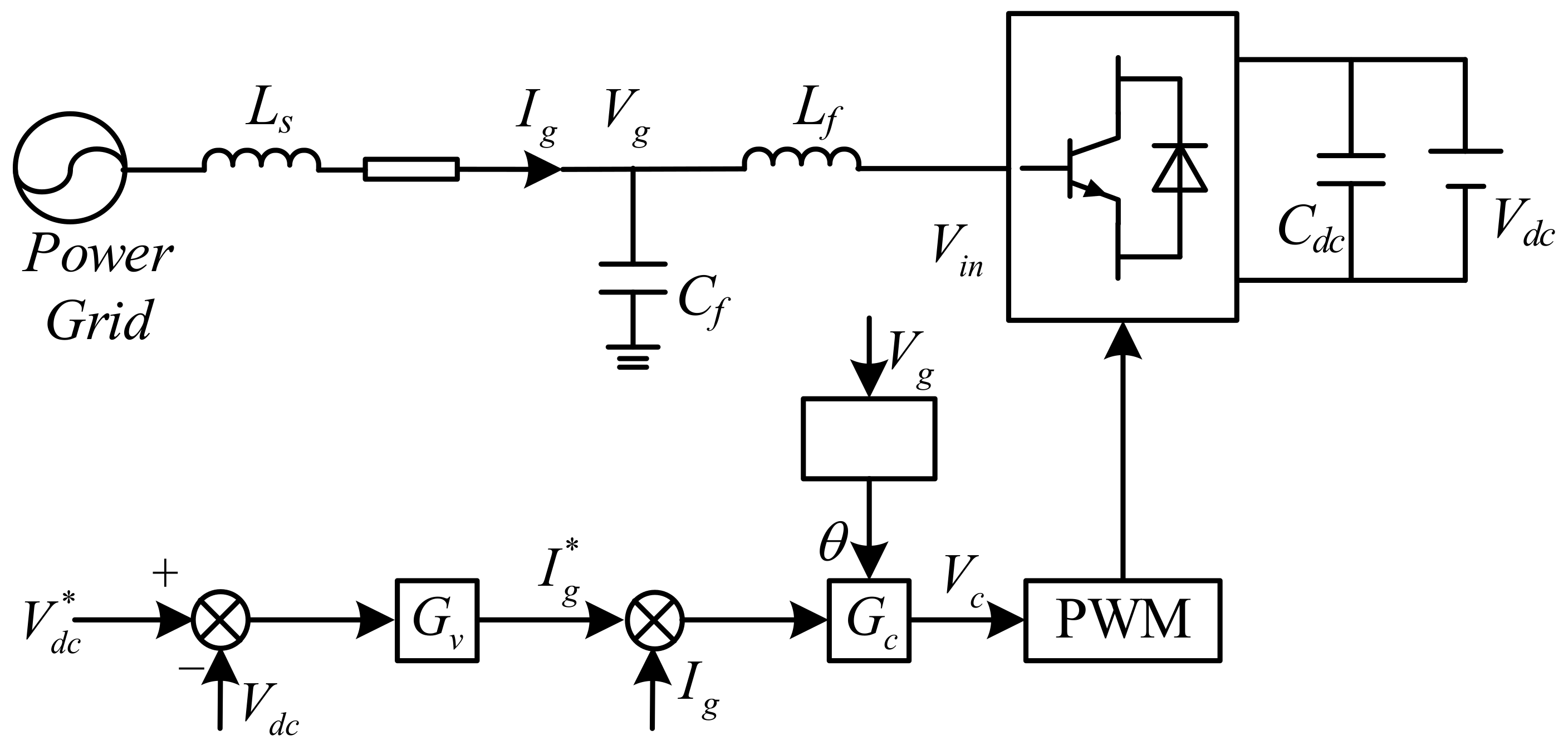
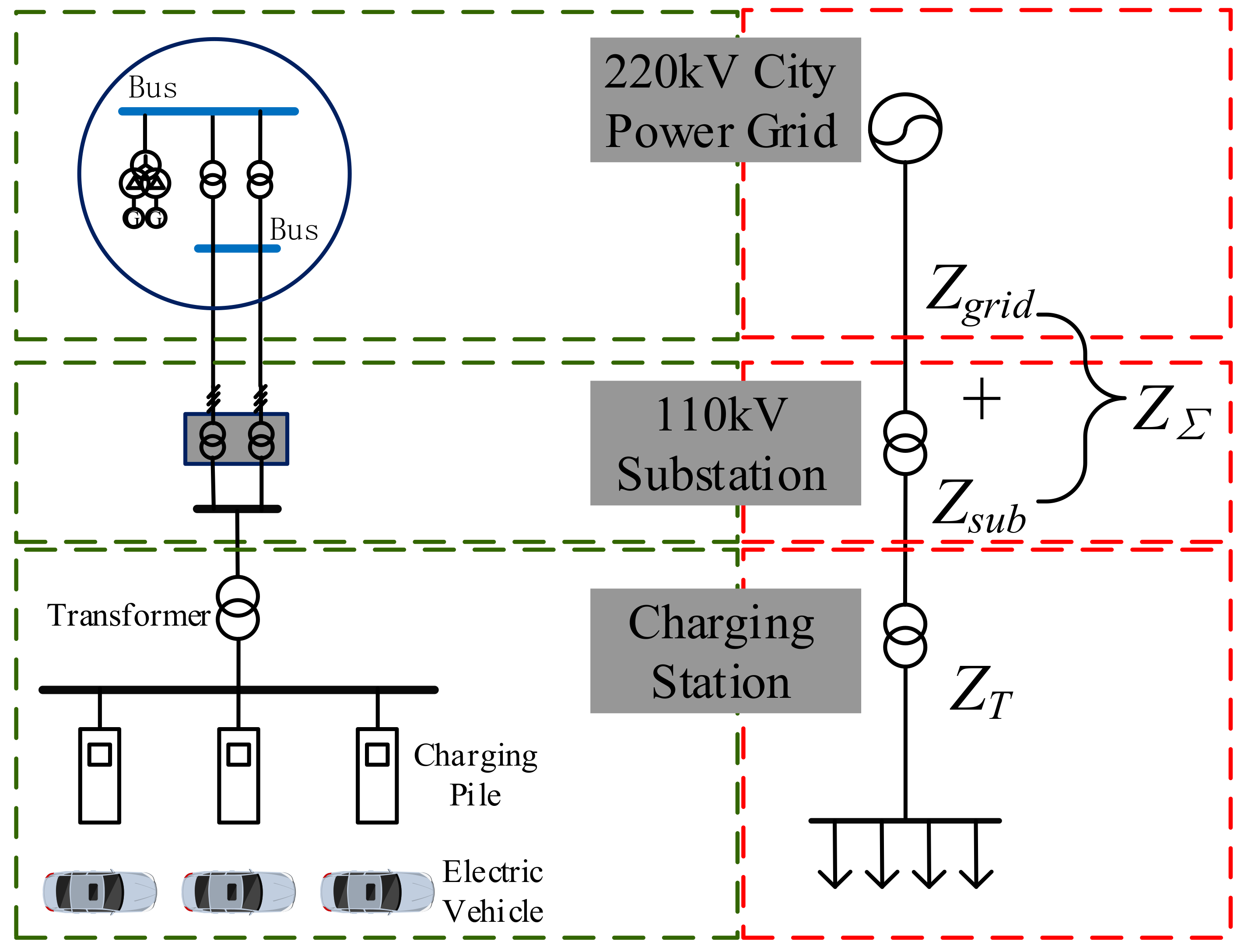
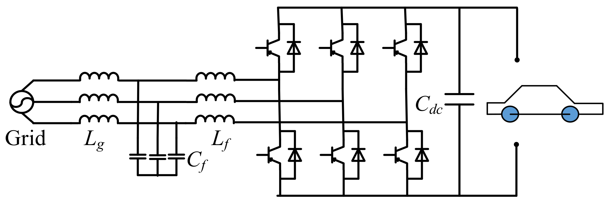
2.1. EV Fast-Charging System Description
2.2. Control System Introduction of the Fast-Charging Pile
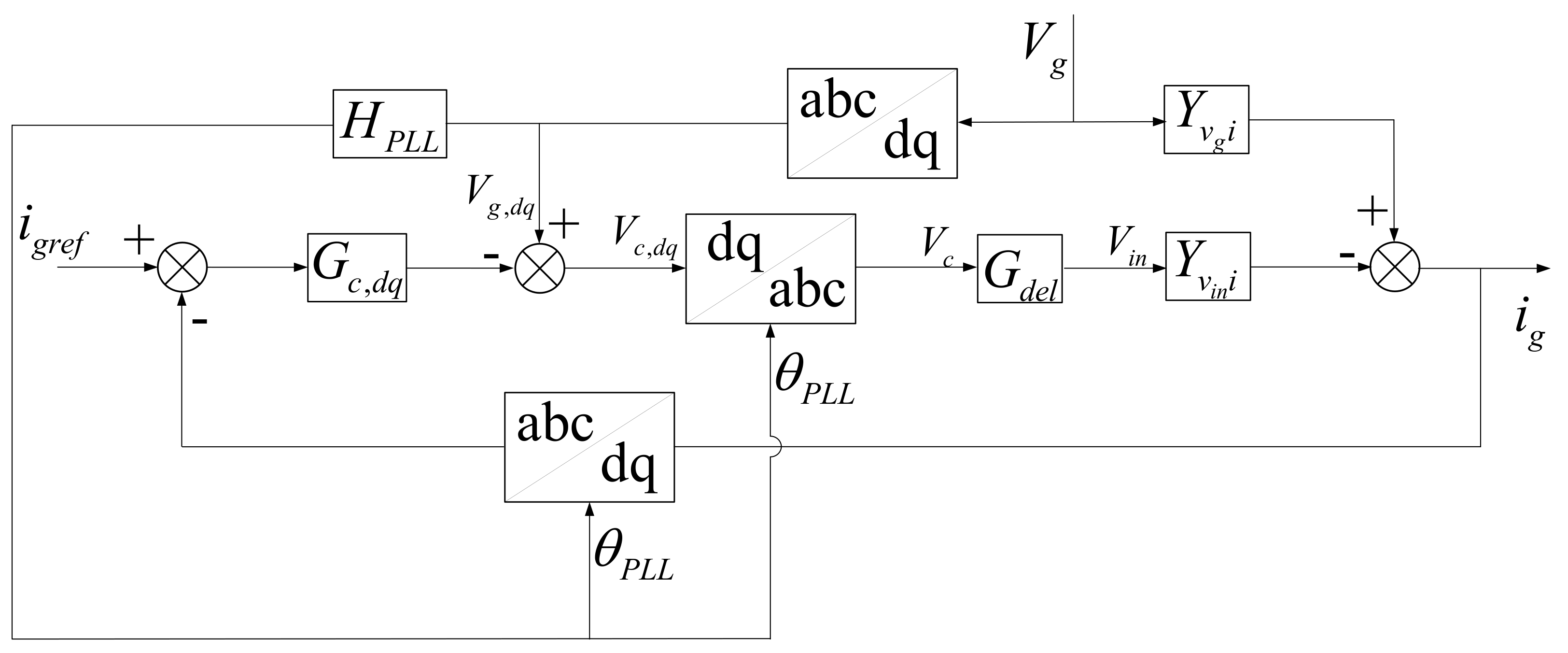
2.3. Current Control Loop Dynamic Modeling
2.4. Dynamic Model of the AC Power Grid
2.4.1. Regional Power Grid Impedance
2.4.2. Transformer Impedance
2.4.3. Distribution Line Impedance
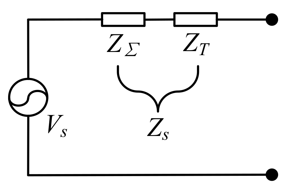
2.4.4. Equivalent Impedance of the Source Subsystem
3. Stability Analysis Method for the MIMO System
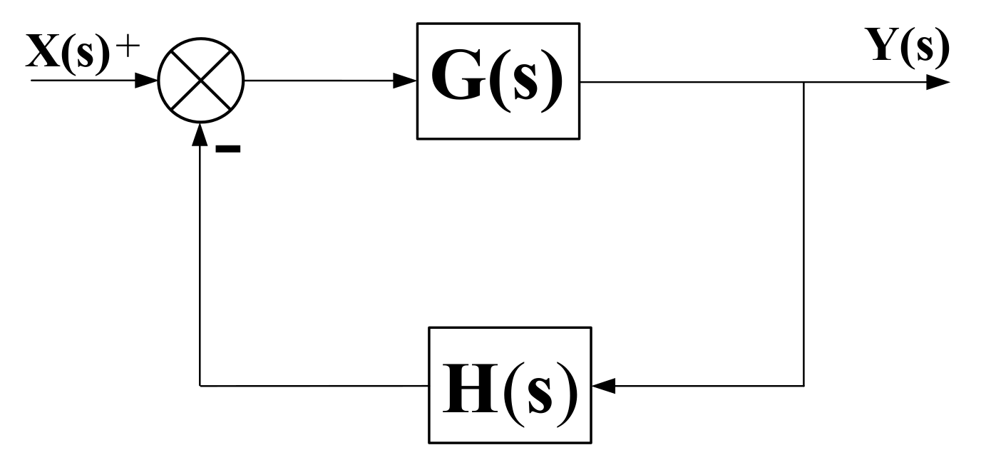
3.1. Generalized Nyquis, Singular Value, and Norm Criterion
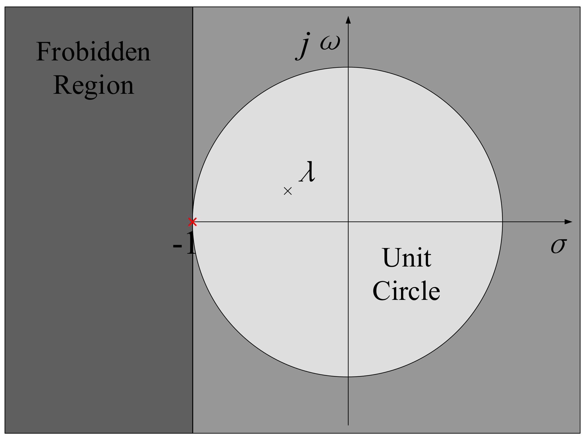
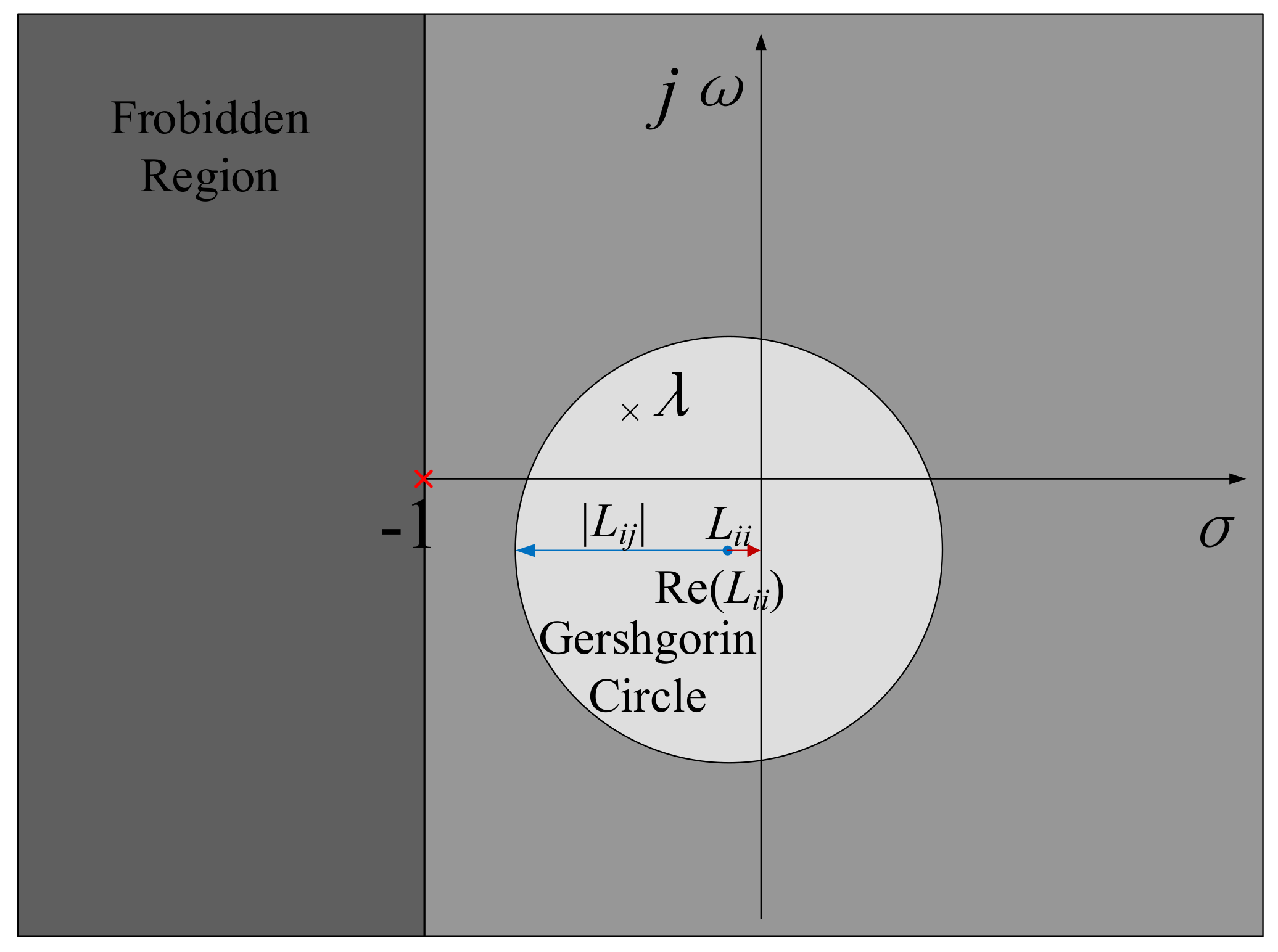
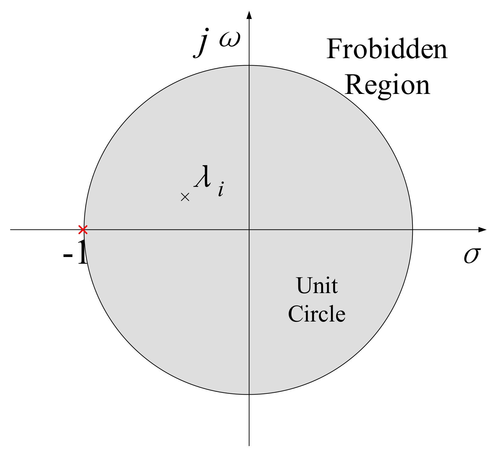
3.2. Modified Forbodden Region-Based Criterion
4. Stability Analysis of the EV Fast-Charging Station
4.1. Parameters of the Fast-Charging Station System
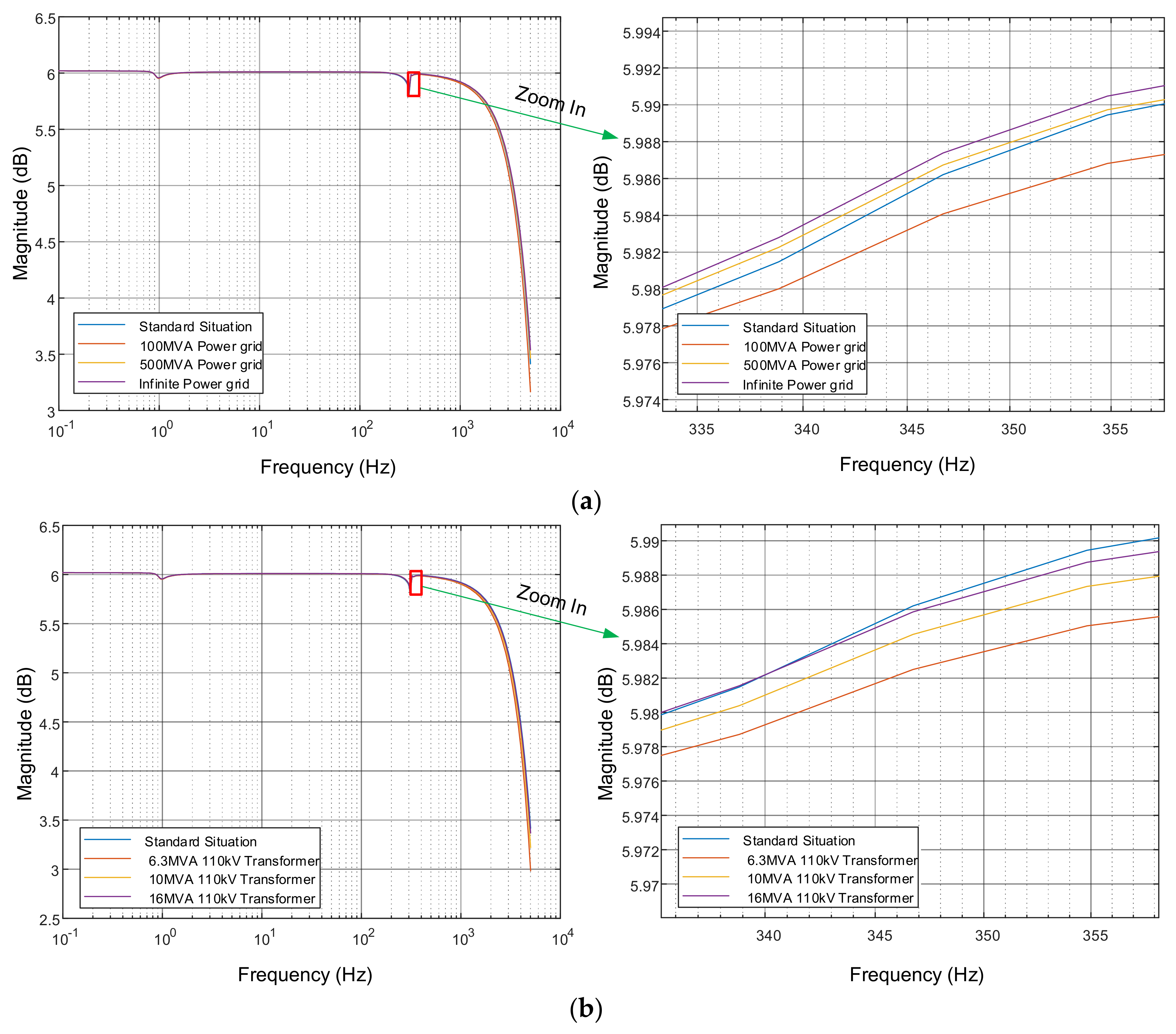
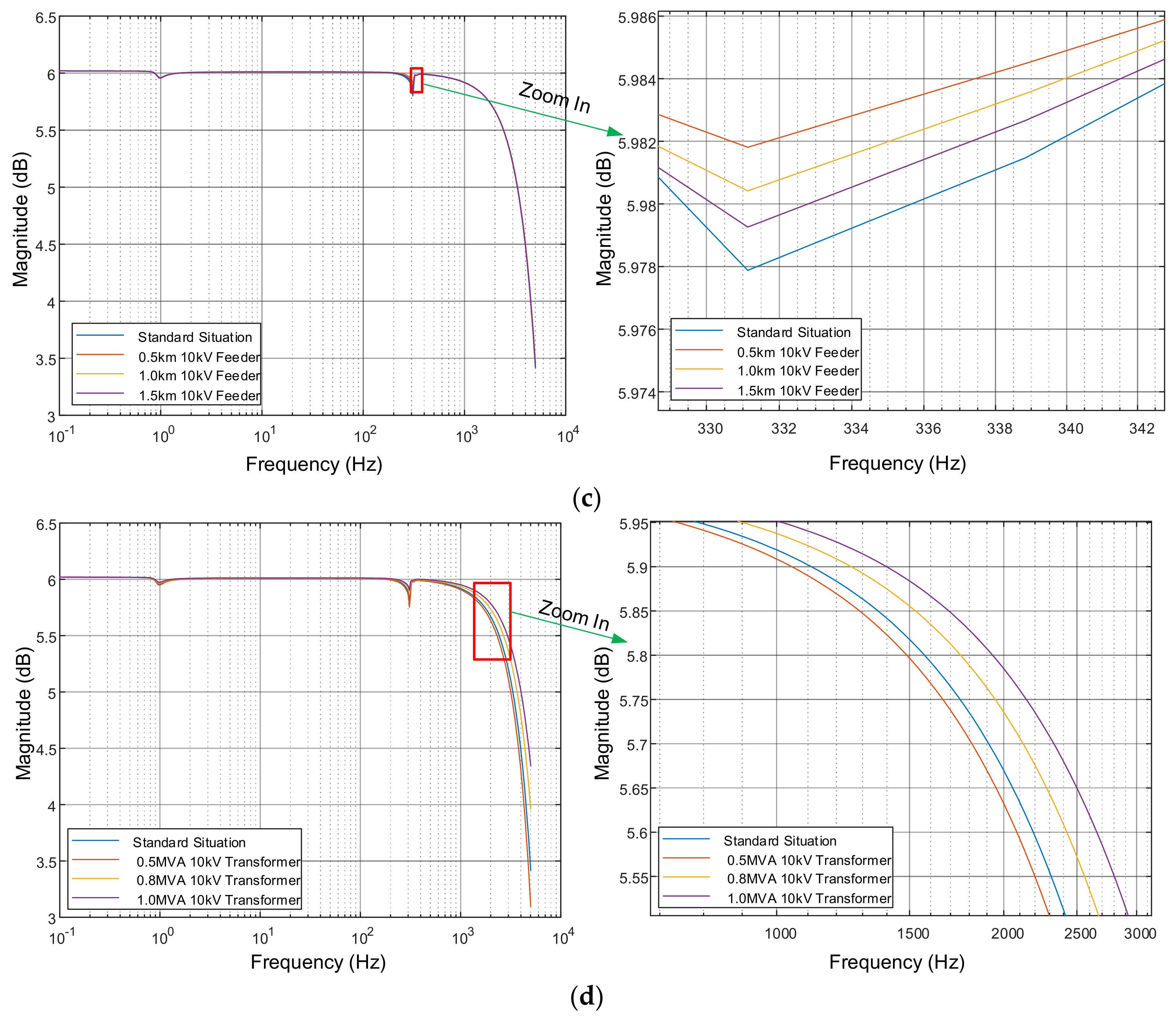
4.2. Power Grid Side Subsystem Influence Factors
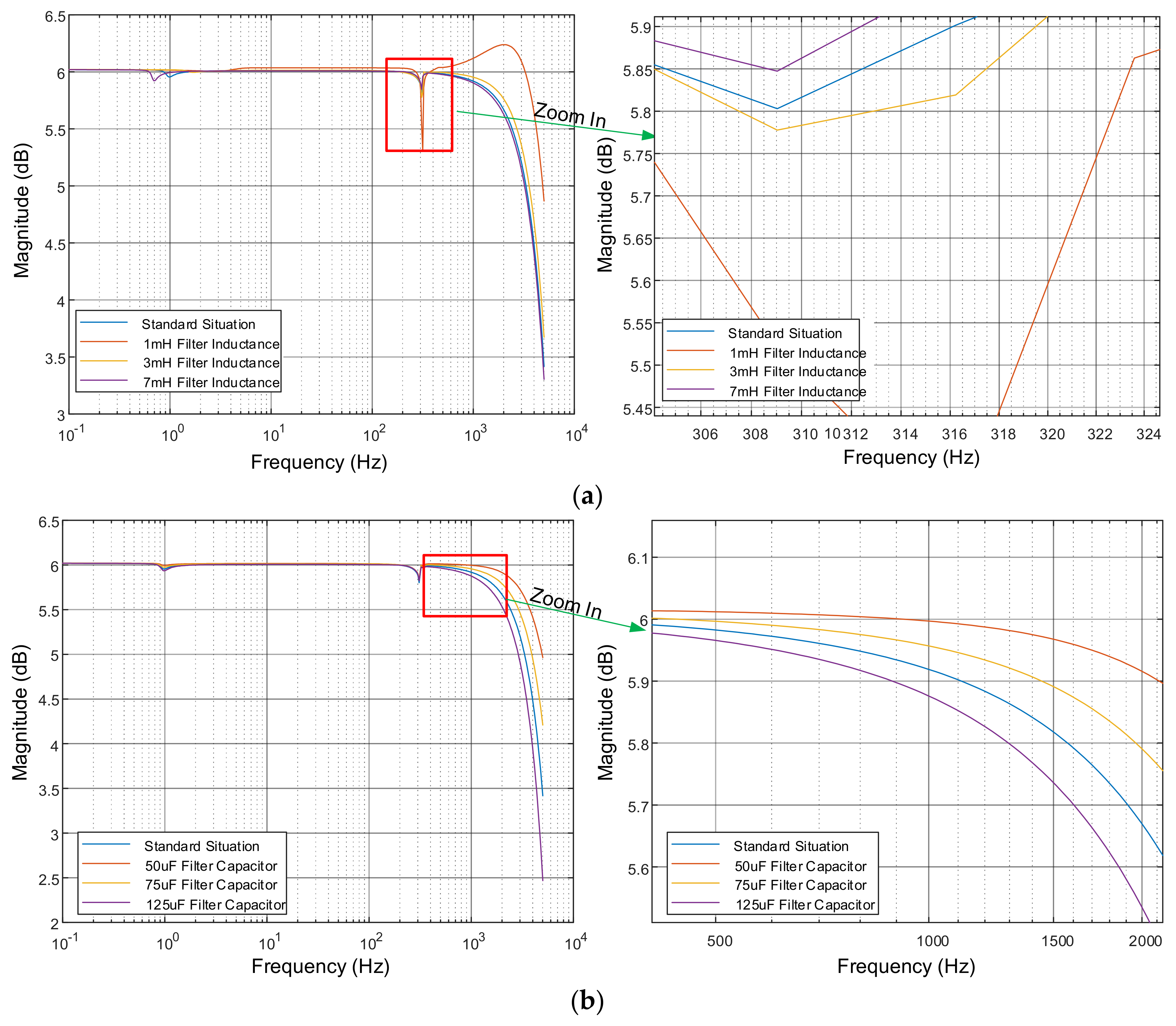
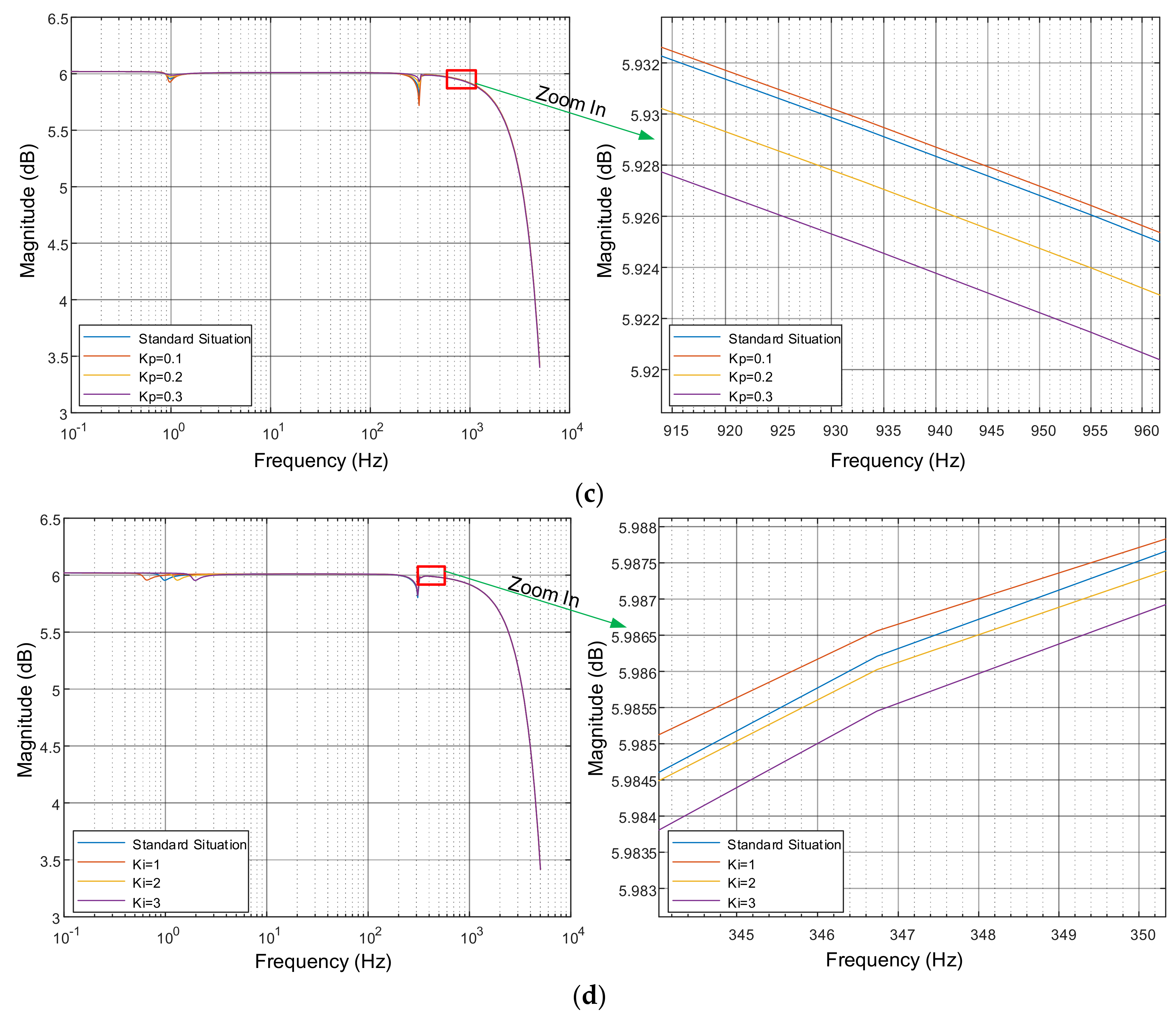
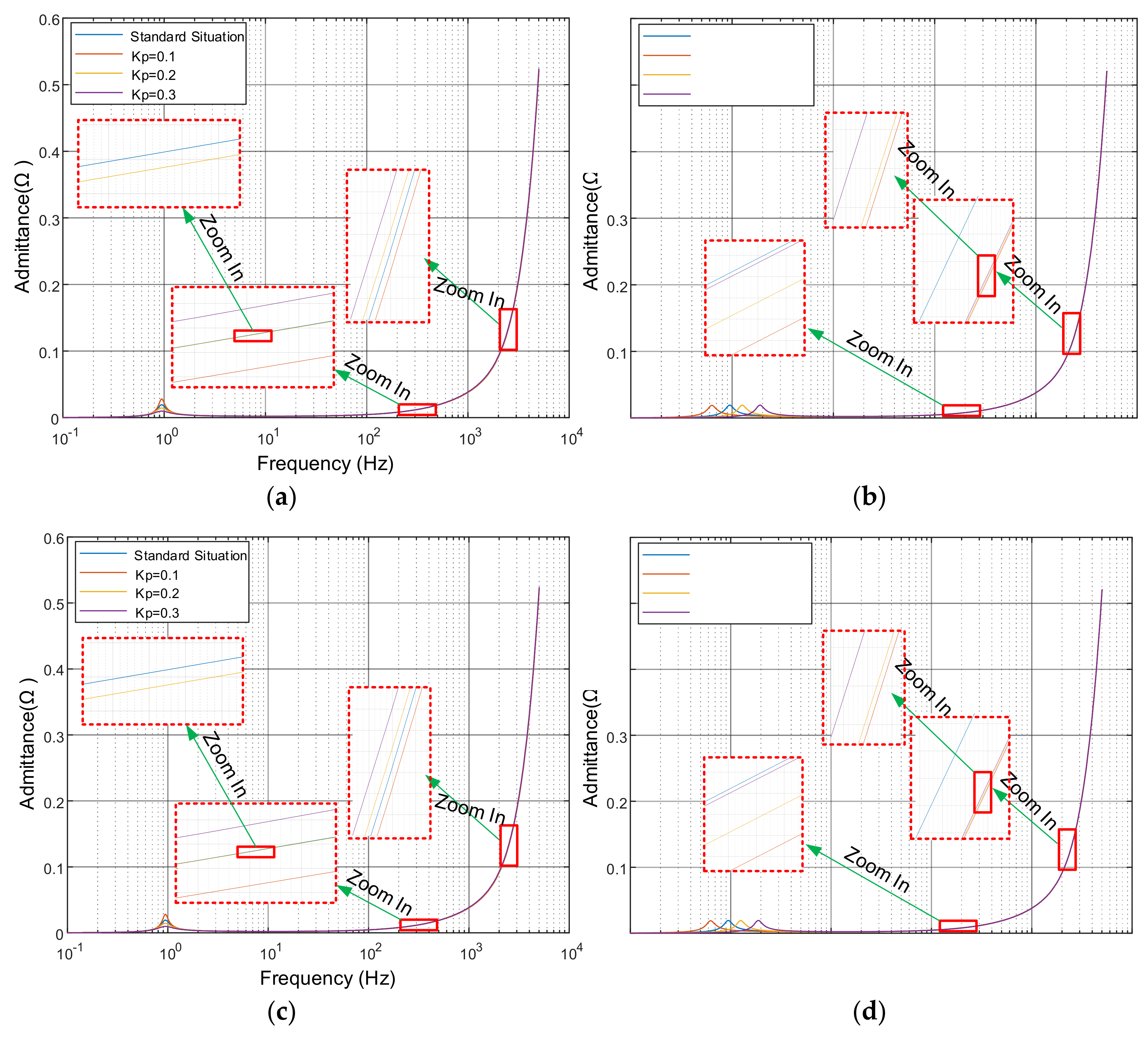
4.3. Fast-Charging Pile-Side Influence Factors
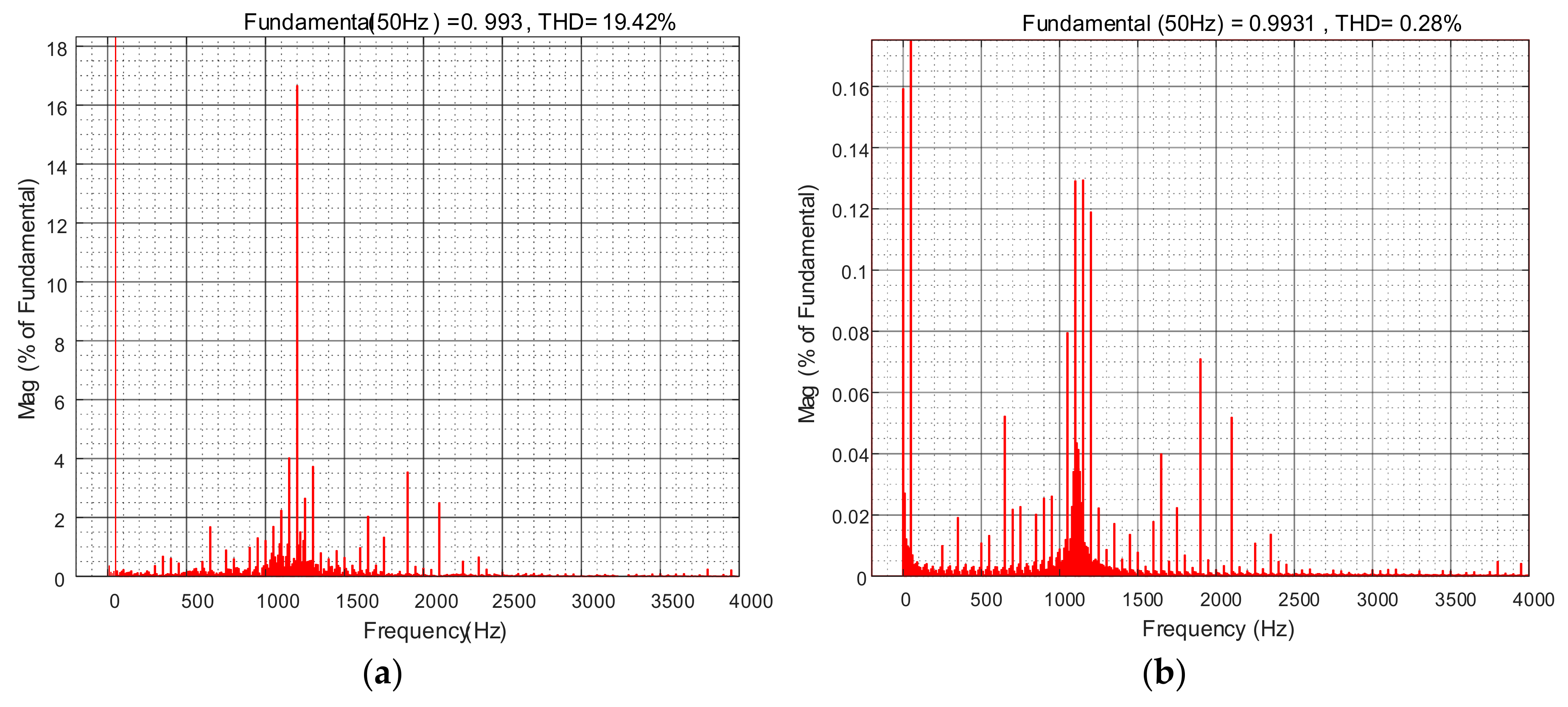
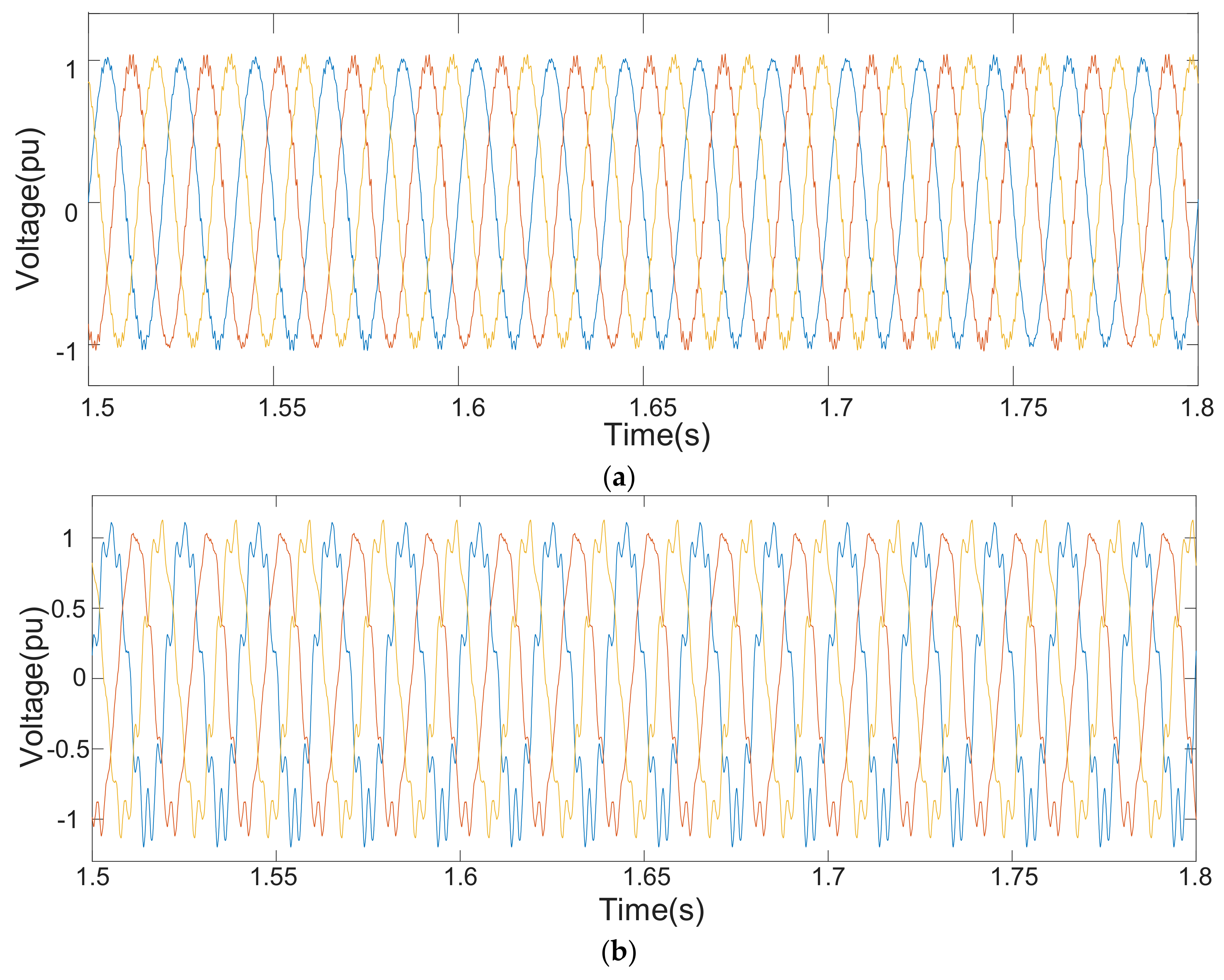
4.4. Time Domain Simulation
5. Conclusions
Author Contributions
Acknowledgments
Conflicts of Interest
Appendix A
Appendix B
References
- Yong, J.Y.; Ramachandaramurthy, V.K.; Tan, K.M.; Mithulananthan, N. A review on the state-of-the-art technologies of electric vehicle, its impacts and prospects. Renew. Sustain. Energy Rev. 2015, 49, 365–385. [Google Scholar] [CrossRef]
- China Plans to Ban Sales of Fossil Fuel Cars Entirely. Available online: https://techcrunch.com/2017/09/10/china-plans-to-ban-sales-of-fossil-fuel-cars-entirely/ (accessed on 11 September 2017).
- Green, R.; Staffell, I. Electricity in Europe: Exiting fossil fuels? Oxf. Rev. Econ. Policy 2016, 32, 282–303. [Google Scholar] [CrossRef]
- Sadeghi-Barzani, P.; Rajabi-Ghahnavieh, A.; Kazemi-Karegar, H. Optimal fast charging station placing and sizing. Appl. Energy 2014, 125, 289–299. [Google Scholar] [CrossRef]
- SAE Electric Vehicle and Plug in Hybrid Electric Vehicle Conductive Charge Coupler. Available online: https://www.sae.org/standards/content/j1772_201710/ (accessed on 13 October 2017).
- Gao, Y.; Ehsani, M. Investigation of battery technologies for the army’s hybrid vehicle application. In Proceedings of the 56th IEEE Conference on Vehicular Technology, Vancouver, BC, Canada, 24–28 September 2002; pp. 1505–1509. [Google Scholar]
- Zhan, Y.J.; Chan, C.C.; Chau, K.T. A novel sliding-mode observer for indirect position sensing of switched reluctance motor drives. IEEE Trans. Ind. Electron. 1999, 46, 390–397. [Google Scholar] [CrossRef] [Green Version]
- Williamson, S.S.; Rathore, A.K.; Musavi, F. Industrial electronics for electric transportation: Current state-of-the-art and future challenges. IEEE Trans. Ind. Electron. 2015, 62, 3021–3032. [Google Scholar] [CrossRef]
- Harnefors, L.; Wang, X.; Yepes, A.G.; Blaabjerg, F. Passivity-based stability assessment of grid-connected VSCs—An overview. IEEE J. Emerg. Sel. Top. Power Electron. 2016, 4, 116–125. [Google Scholar] [CrossRef]
- Ashabani, M.; Mohamed, Y.A.R.I.; Mirsalim, M.; Aghashabani, M. Multivariable Droop Control of Synchronous Current Converters in Weak Grids Microgrids with Decoupled dq-Axes Currents. IEEE Trans. Smart Grid 2015, 6, 1610–1620. [Google Scholar] [CrossRef]
- Wang, H.; Mingli, W.; Sun, J. Analysis of low-frequency oscillation in electric railways based on small-signal modeling of vehicle-grid system in dq frame. IEEE Trans. Power Electron. 2015, 30, 5318–5330. [Google Scholar] [CrossRef]
- Xiao, X.; Zhang, J.; Guo, C.; Yang, L. A new subsynchronous torsional interaction and its mitigation countermeasures. In Proceedings of the 2013 IEEE Conference on Energytech, Cleveland, OH, USA, 21–23 May 2013; pp. 1–5. [Google Scholar]
- Wang, L.; Xie, X.; Jiang, Q.; Liu, H.; Li, Y.; Liu, H. Investigation of SSR in practical DFIG-based wind farms connected to a series compensated power system. IEEE Trans. Power Syst. 2015, 30, 2772–2779. [Google Scholar] [CrossRef]
- Kwon, J.; Wang, X.; Blaabjerg, F.; Bak, C.L.; Sularea, V.S.; Busca, C. Harmonic Interaction Analysis in a Grid-Connected Converter Using Harmonic State-Space (HSS) Modeling. IEEE Trans. Power Electron. 2016, 32, 6823–6835. [Google Scholar] [CrossRef]
- Wen, B.; Boroyevich, D.; Burgos, R.; Mattavelli, P.; Shen, Z. Analysis of D-Q small-signal impedance of grid-tied inverters. IEEE Trans. Power Electron. 2016, 32, 675–687. [Google Scholar] [CrossRef]
- Cho, Y.; Hur, K.; Kang, Y.C.; Muljadi, E. Impedance-Based Stability Analysis in Grid Interconnection Impact Study Owing to the Increased Adoption of Converter-Interfaced Generators. Energies 2017, 10, 1355. [Google Scholar] [CrossRef]
- Aldhaheri, A.; Etemadi, A. Impedance Decoupling in DC Distributed Systems to Maintain Stability and Dynamic Performance. Energies 2017, 10, 470. [Google Scholar] [CrossRef]
- Cespedes, M.; Sun, J. Impedance modeling and analysis of grid-connected voltage-source converters. IEEE Trans. Power Electron. 2014, 29, 1254–1261. [Google Scholar] [CrossRef]
- Sun, J. Impedance-based stability criterion for grid-connected inverters. IEEE Trans. Power Electron. 2011, 26, 3075–3078. [Google Scholar] [CrossRef]
- MacFarlane, A.G.J. Complex Variable Methods for Linear Multivariable Feedback Systems; Taylor & Francis, Inc.: Oxfordshire, UK, 1980. [Google Scholar]
- Belkhayat, M. Stability Criteria for AC Power Systems with Regulated Loads. Ph.D. Thesis, Purdue University, West Lafayette, IN, USA, 1997. [Google Scholar]
- Chandrasekaran, S.; Borojevic, D.; Lindner, D. Input filter interaction in three-phase AC-DC converters. In Proceedings of the 30th Annual IEEE Conference on Power Electronics Specialists Conference, Charleston, SC, USA, 1 July 1999; pp. 987–992. [Google Scholar]
- Burgos, R.; Boroyevic, D.; Wang, F.; Karimi, K.; Francis, G. On the Ac stability of high power factor three-phase rectifiers. In Proceedings of the 2010 IEEE Conference on Energy Conversion Congress and Exposition (ECCE), Atlanta, GA, USA, 12–16 September 2010; pp. 2047–2054. [Google Scholar]
- Burgos, R.; Boroyevic, D.; Wang, F.; Karimi, K.; Francis, G. Ac stability of high power factor multi-pulse rectifiers. In Proceedings of the 2011 IEEE Conference on Energy Conversion Congress and Exposition (ECCE), Phoenix, AZ, USA, 17–22 September 2011; pp. 3758–3765. [Google Scholar]
- Mao, H.; Boroyevic, D.; Lee, F. Novel reduced-order small-signal model of a three-phase PWM rectifier and its application in control design and system analysis. IEEE Trans. Power Electron. 1998, 13, 511–521. [Google Scholar]
- Liu, F.; Liu, J.; Zhang, H.; Xue, D.; Hasan, S.U.; Zhou, L. Modified norm type stability criterion for cascade AC system. In Proceedings of the 2013 IEEE Conference on Energy Conversion Congress and Exposition (ECCE), Denver, CO, USA, 15–19 September 2013; pp. 442–447. [Google Scholar]
- Bo, W.; Boroyevich, D.; Burgos, R.; Mattavelli, P.; Zhiyu, S. D-Q impedance specification for balanced three-phase AC distributed power system. In Proceedings of the 2015 IEEE Conference on Applied Power Electronics Conference and Exposition (APEC), Charlotte, NC, USA, 15–19 March 2015; pp. 2757–2771. [Google Scholar]
- Liao, Y.; Liu, Z.; Zhang, G.; Xiang, C. Vehicle-Grid System Modeling and Stability Analysis with Forbidden Region-Based Criterion. IEEE Trans. Power Electron. 2017, 32, 3499–3512. [Google Scholar] [CrossRef]
- Wang, X.; Blaabjerg, F.; Wu, W. Modeling and Analysis of Harmonic Stability in an AC Power-Electronics-Based Power System. IEEE Trans. Power Electron. 2014, 29, 6421–6432. [Google Scholar] [CrossRef]
- Harnefors, L. Modeling of three-phase dynamic systems using complex transfer functions and transfer matrices. IEEE Trans. Ind. Electron. 2007, 54, 2239–2248. [Google Scholar] [CrossRef]
- Wang, X.; Harnefors, L.; Blaabjerg, F. Unified Impedance Model of Grid-Connected Voltage-Source Converters. IEEE Trans. Power Electron. 2017, 33, 1775–1787. [Google Scholar] [CrossRef]


| Category | Value |
|---|---|
| AC side voltage (Vg) | 400 V |
| DC side voltage (Vdc) | 600 V |
| Sampling period (Ts) | 5 × 10⁻⁴ s |
| Filter inductance (Lf) | 0.005 H |
| Filter conductance (Cf) | 99 × 10−6 F |
| Switching frequency (fs) | 2000 Hz |
| Grid fundmental frequency (f) | 50 Hz |
| Category | Value |
|---|---|
| Proportional gain (Kp) | 0.15 |
| Integral gain (Ki) | 1.5 |
| Category | Value |
|---|---|
| Regional Short Circuit Capacity(S) | 300 MVA |
| Ratio of inductance and reactance(kx/r) | 15 |
| 10 kV feeder cable(Lfeeder) | 2 km |
| Category | Voltage Ratio | Capacity (MVA) | Short Circuit Power (kW) | Impedance Voltage |
|---|---|---|---|---|
| 110 kV Transformer | 110 kV/10 kV | 20 | 88.4 | 10.5 |
| 10 kV Transformer | 10 kV/0.4 kV | 0.63 | 8.169 | 4.5 |
| Influence Factor | Variation | Stability | Grid Side Impedance |
|---|---|---|---|
| SSC | ↑ | ↑ | ↓ |
| ST110 | ↑ | ↑ | ↓ |
| Lfeeder | ↓ | ↑ | ↓ |
| ST10 | ↑ | ↑ | ↓ |
| Influence factor | Variation | Stability | Charging Pile Side Admittance |
|---|---|---|---|
| Lf | ↑ | ↑ | Uncertain |
| Cf | ↑ | ↓ | ↑ |
| Kp | ↑ | ↓ | Uncertain |
| Ki | ↑ | ↓ | Uncertain |
© 2018 by the authors. Licensee MDPI, Basel, Switzerland. This article is an open access article distributed under the terms and conditions of the Creative Commons Attribution (CC BY) license (http://creativecommons.org/licenses/by/4.0/).
Share and Cite
Wang, X.; He, Z.; Yang, J. Electric Vehicle Fast-Charging Station Unified Modeling and Stability Analysis in the dq Frame. Energies 2018, 11, 1195. https://doi.org/10.3390/en11051195
Wang X, He Z, Yang J. Electric Vehicle Fast-Charging Station Unified Modeling and Stability Analysis in the dq Frame. Energies. 2018; 11(5):1195. https://doi.org/10.3390/en11051195
Chicago/Turabian StyleWang, Xiang, Zhengyou He, and Jianwei Yang. 2018. "Electric Vehicle Fast-Charging Station Unified Modeling and Stability Analysis in the dq Frame" Energies 11, no. 5: 1195. https://doi.org/10.3390/en11051195
APA StyleWang, X., He, Z., & Yang, J. (2018). Electric Vehicle Fast-Charging Station Unified Modeling and Stability Analysis in the dq Frame. Energies, 11(5), 1195. https://doi.org/10.3390/en11051195