A Novel Three-Level Voltage Source Converter for AC–DC–AC Conversion

 ,
, 
Abstract
:1. Introduction
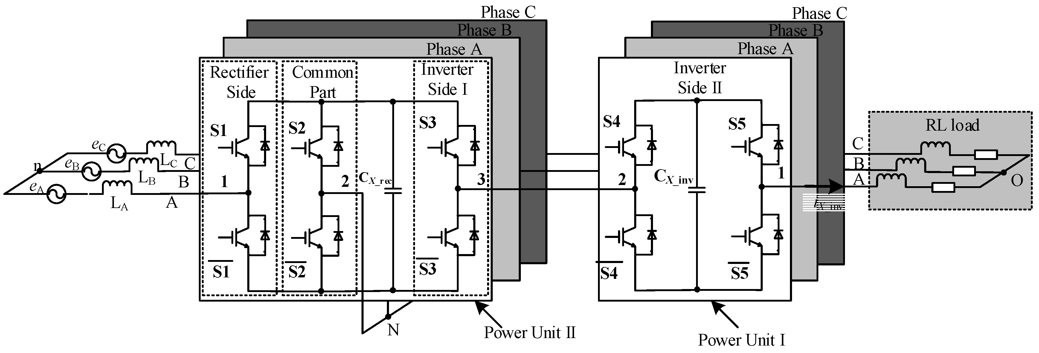
2. Circuit Configuration of Proposed Three-Level Voltage Source Converter
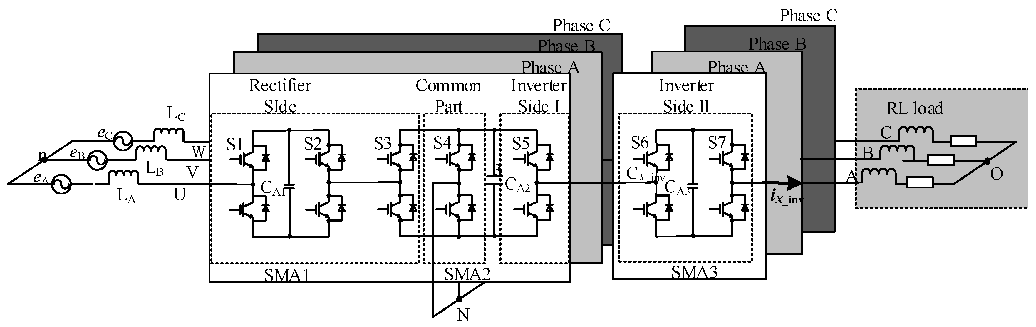
2.1. Circuit Configuration
2.2. Working Principle of Rectifier Side
2.3. Working Principle of Inverter Side I
2.4. Master–Slave Control Principle
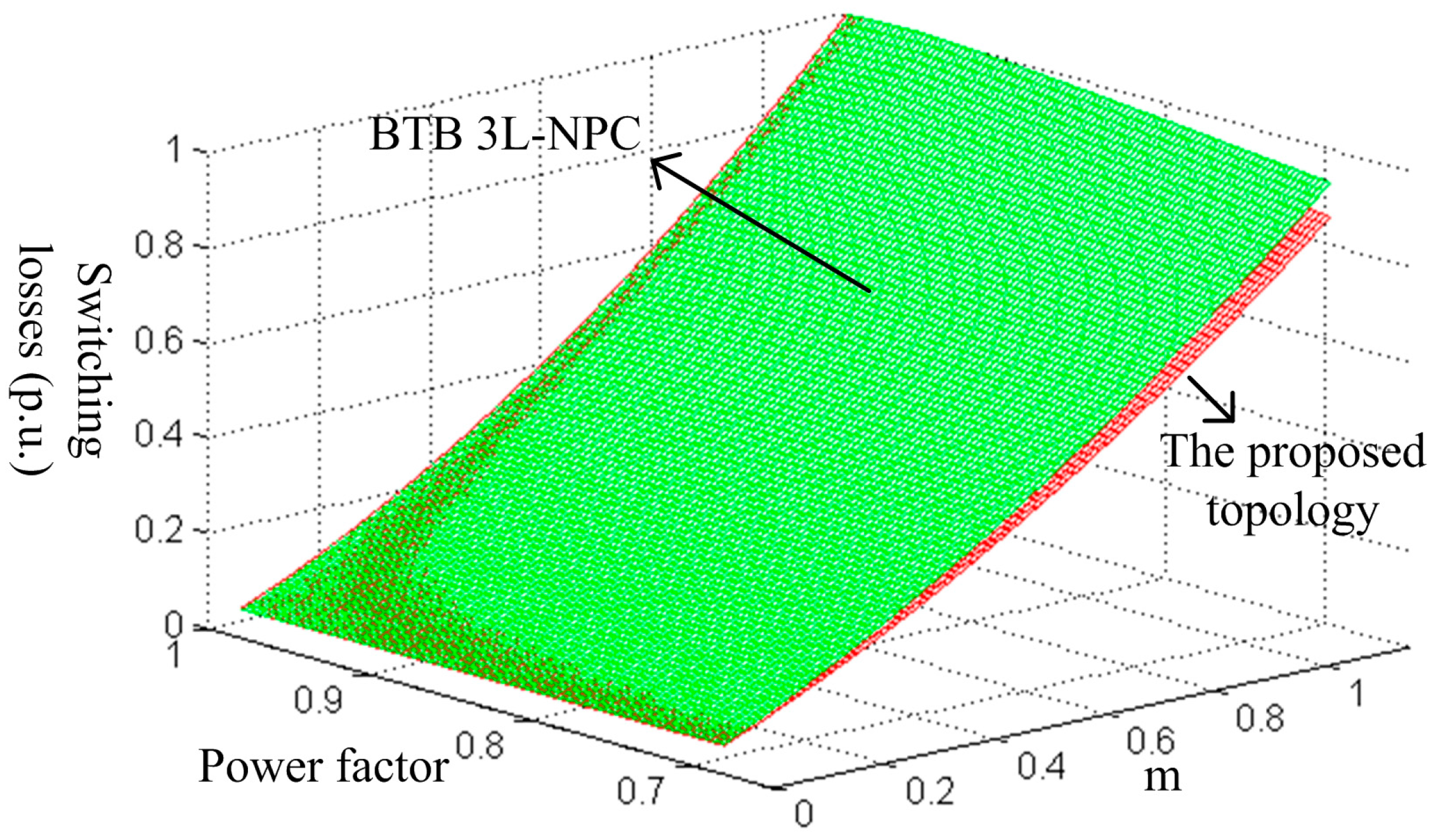
2.5. Comparison with Classic Multilevel Topologies
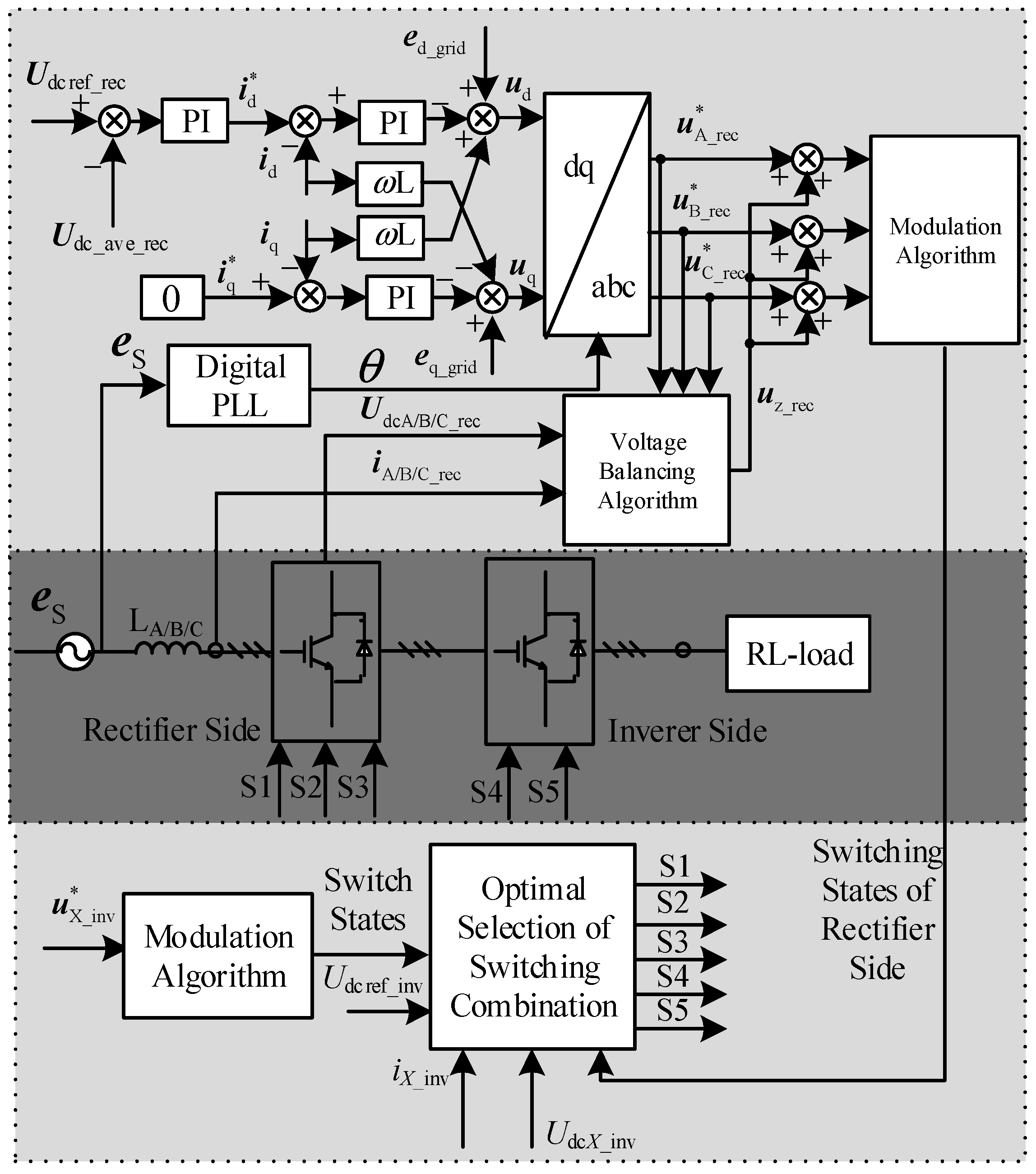
3. Control Method of the Proposed Three-Level Voltage Source Converter
3.1. Control Method
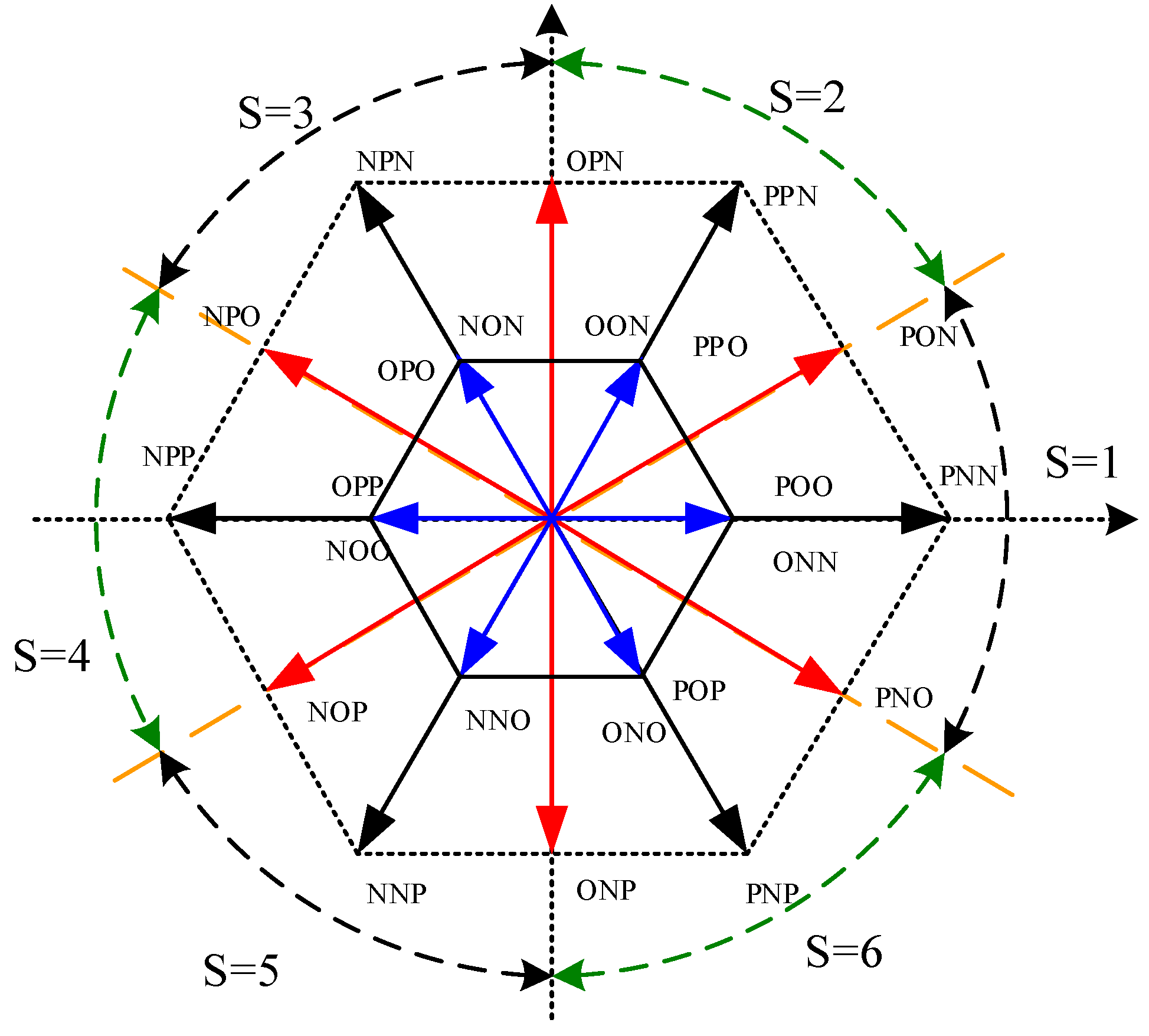
3.2. Modulation Algorithm
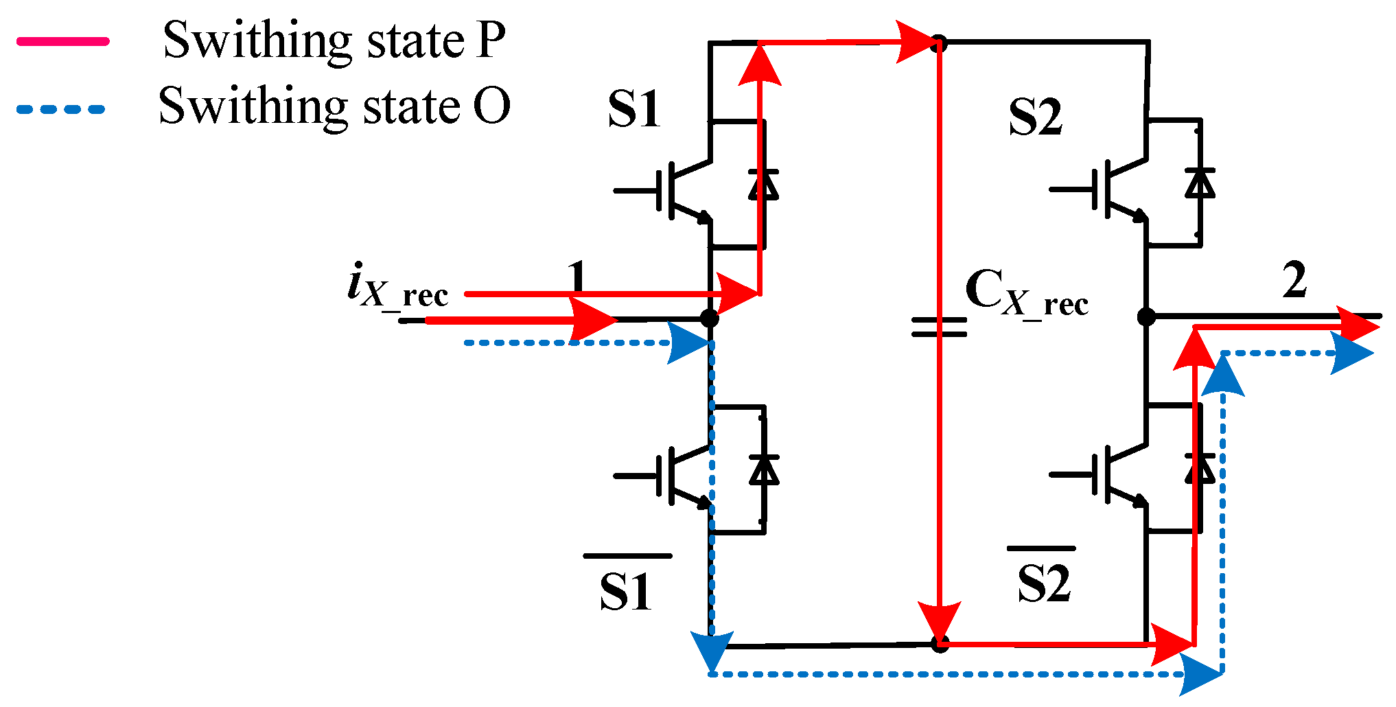
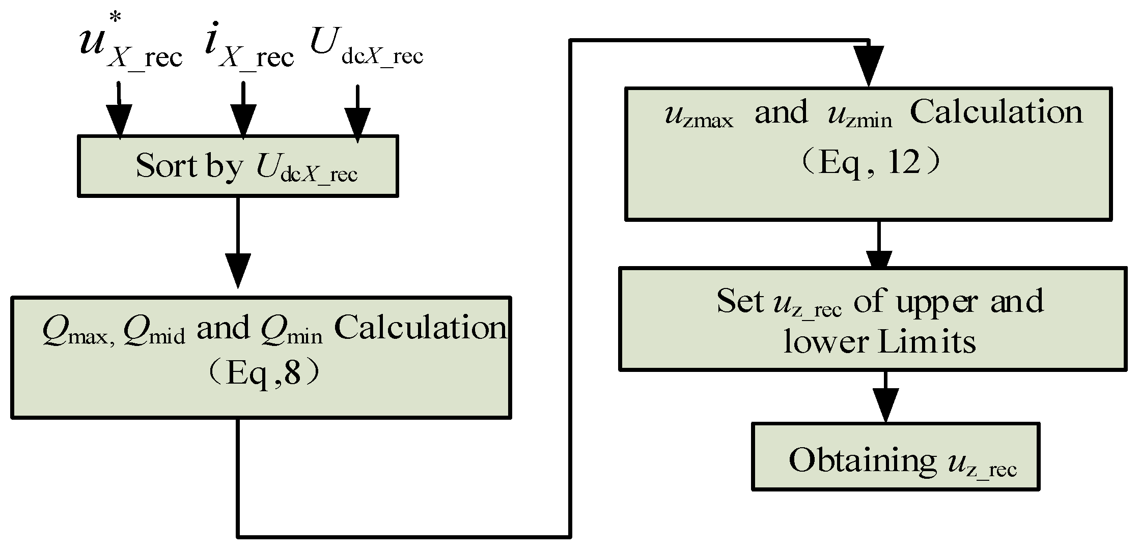
3.3. Voltage Balancing Algorithm of Rectifier Side
- QX, u*X_rec, and iX_rec are sorted according to UdcX_rec. In order to realize the voltage balancing, QX should satisfy Equation (7).QX is defined as Equation (8).If iX_rec > 0 and (u*X_rec − uz_rec) > 0, uX_rec consists of P/O. The current paths of S1S2 are shown in Figure 5. Obviously, QX > 0 and CX_rec is charged in this case. CX_rec is discharged within Ts when iX_rec < 0 and (u*X_rec − uz_rec) > 0.
- Substituting (8) into (7) gives (9).utemp1 = b1/a1, and utemp2 = b2/a2.
- The range of uz_rec can be obtained from Equation (9), and uz_rec can take any value within the range. However, it should satisfy Equation (11) to acquire a linear modulation.
- Calculating the limit value of uz_rec: the corresponding limitations of the injected zero-sequence voltages are given in (12).
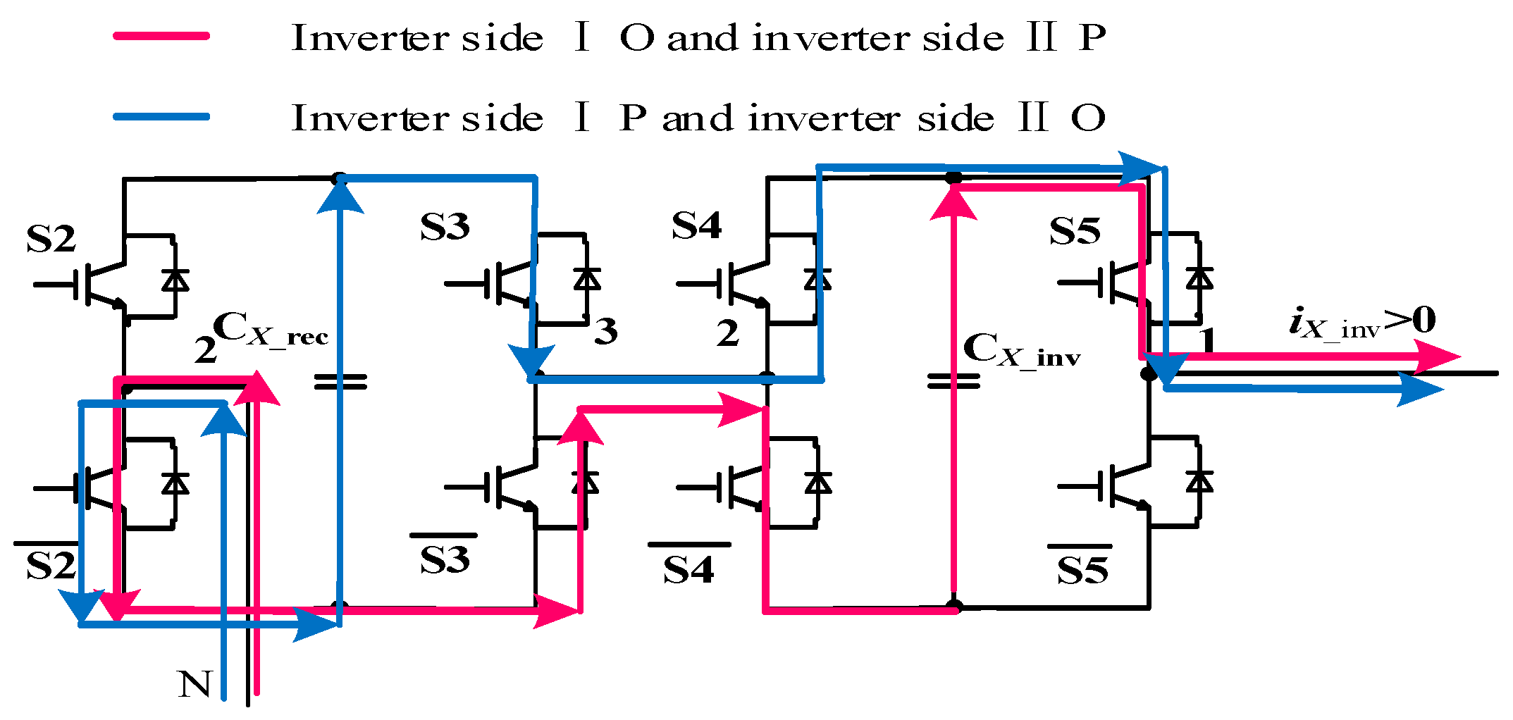
3.4. Voltage Balancing Method of Inverter Side
3.4.1. Effect of the Switching States on the Capacitors Voltages
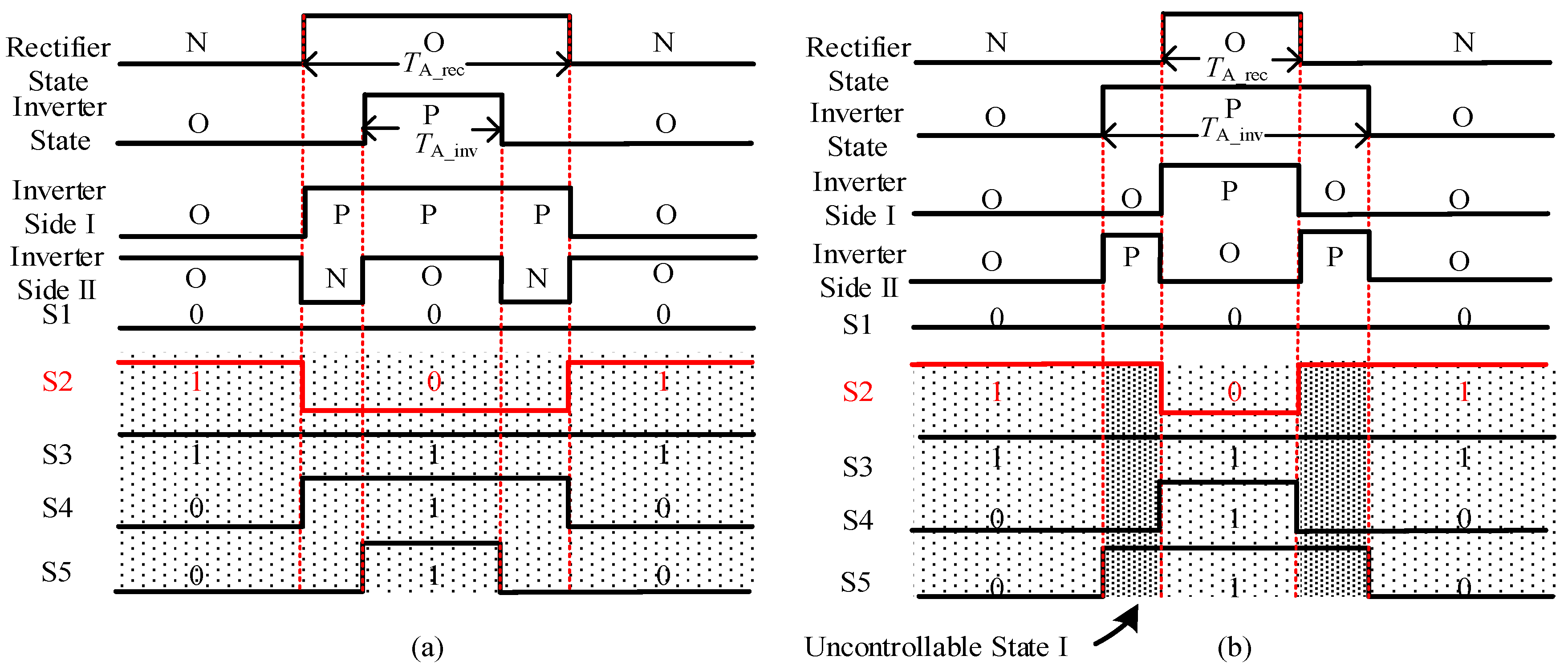
3.4.2. Optimal Selection of Switching Combination (OSSC)
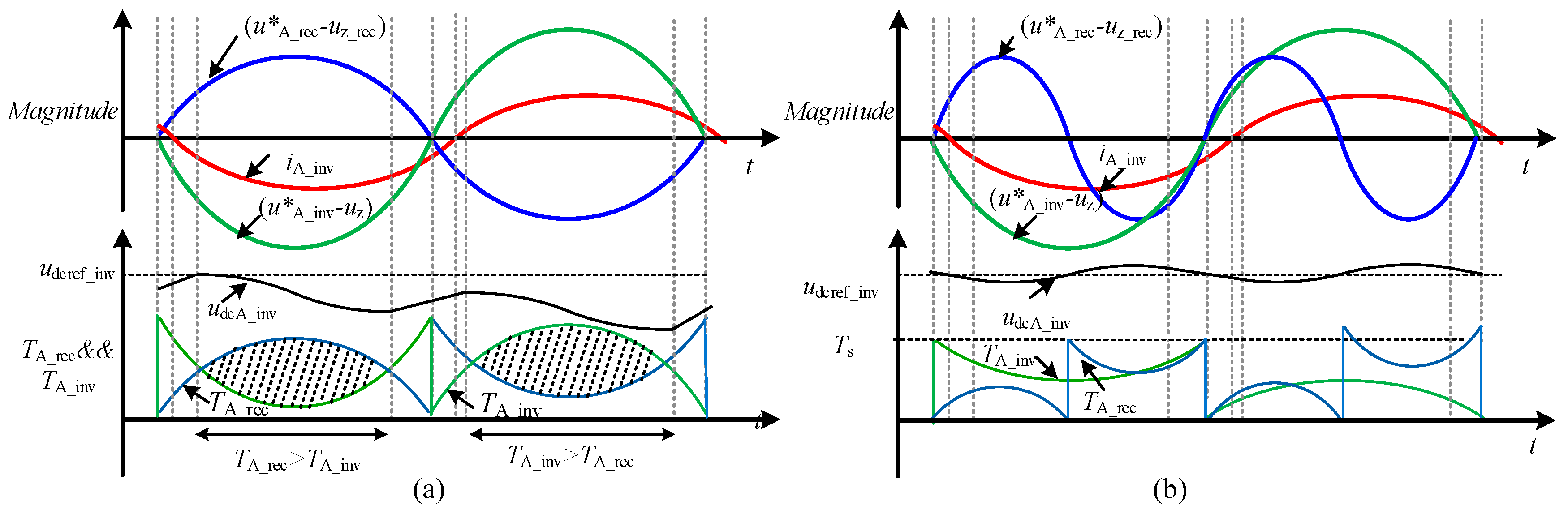
3.5. Calculation of Duration Time of Each Arm
4. Simulation and Experimental Analysis
4.1. Operation of the Proposed Three-Level Voltage Source Converter
4.1.1. Ideal Operation Condition
4.1.2. General Operation Condition
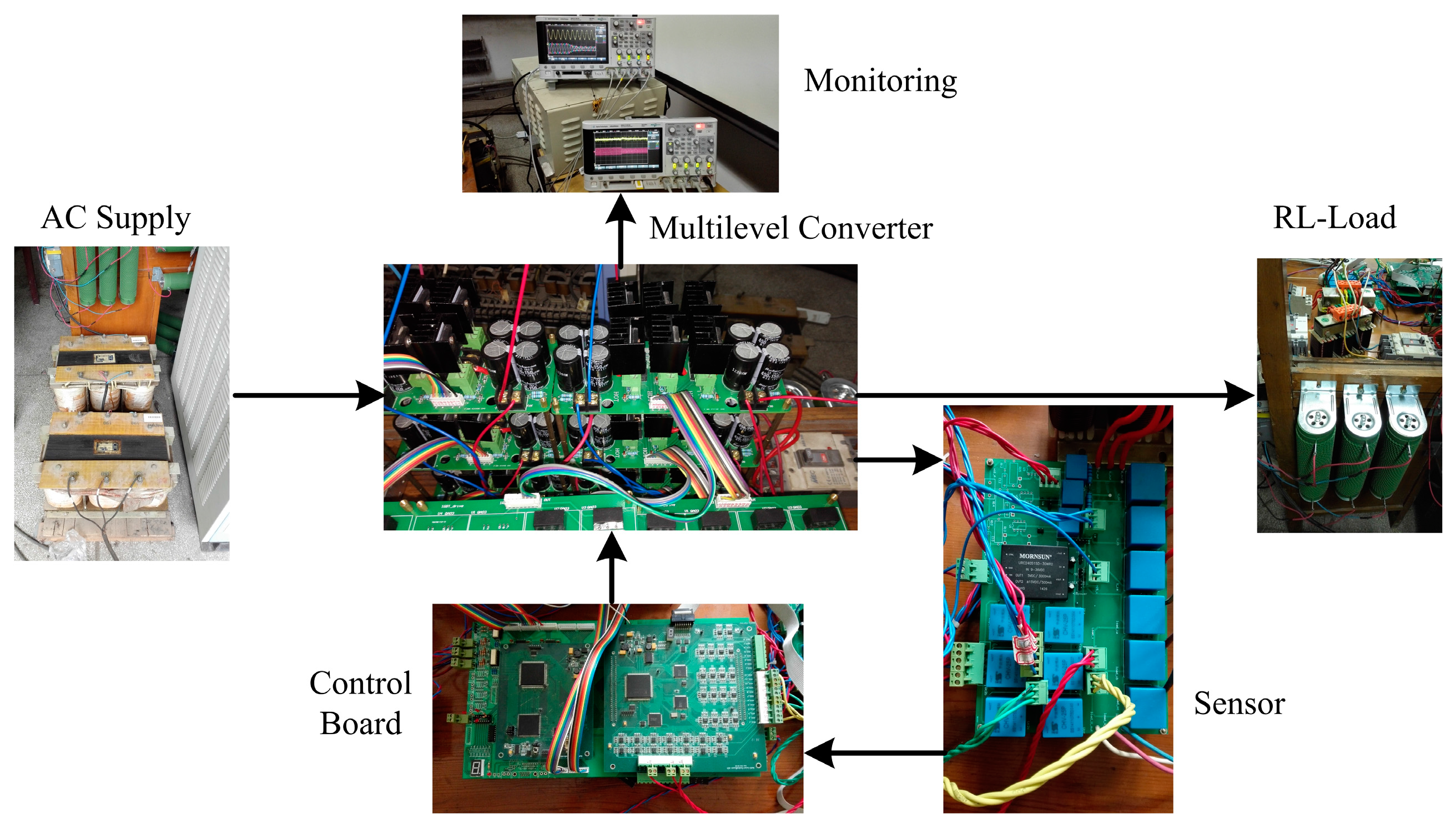
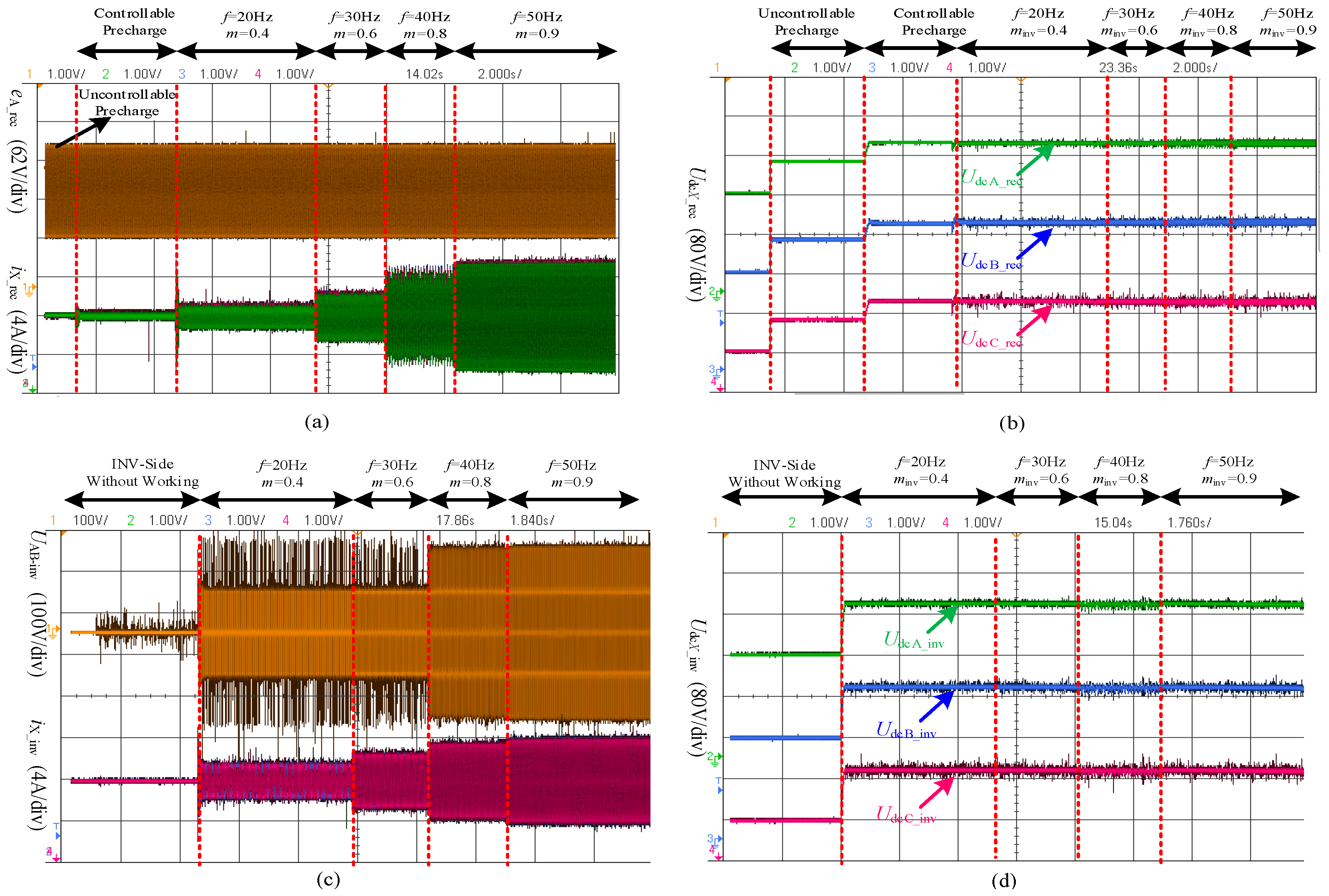
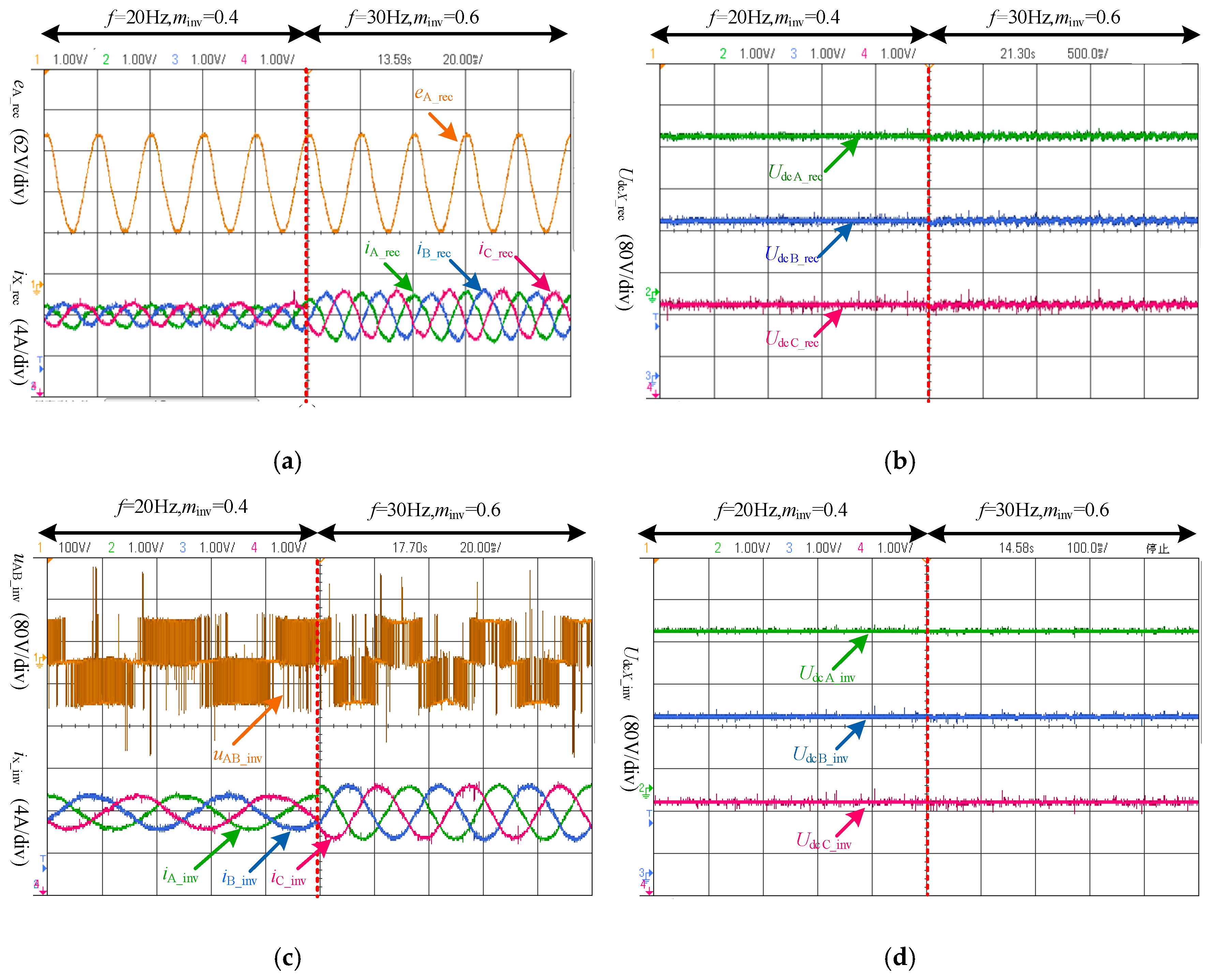
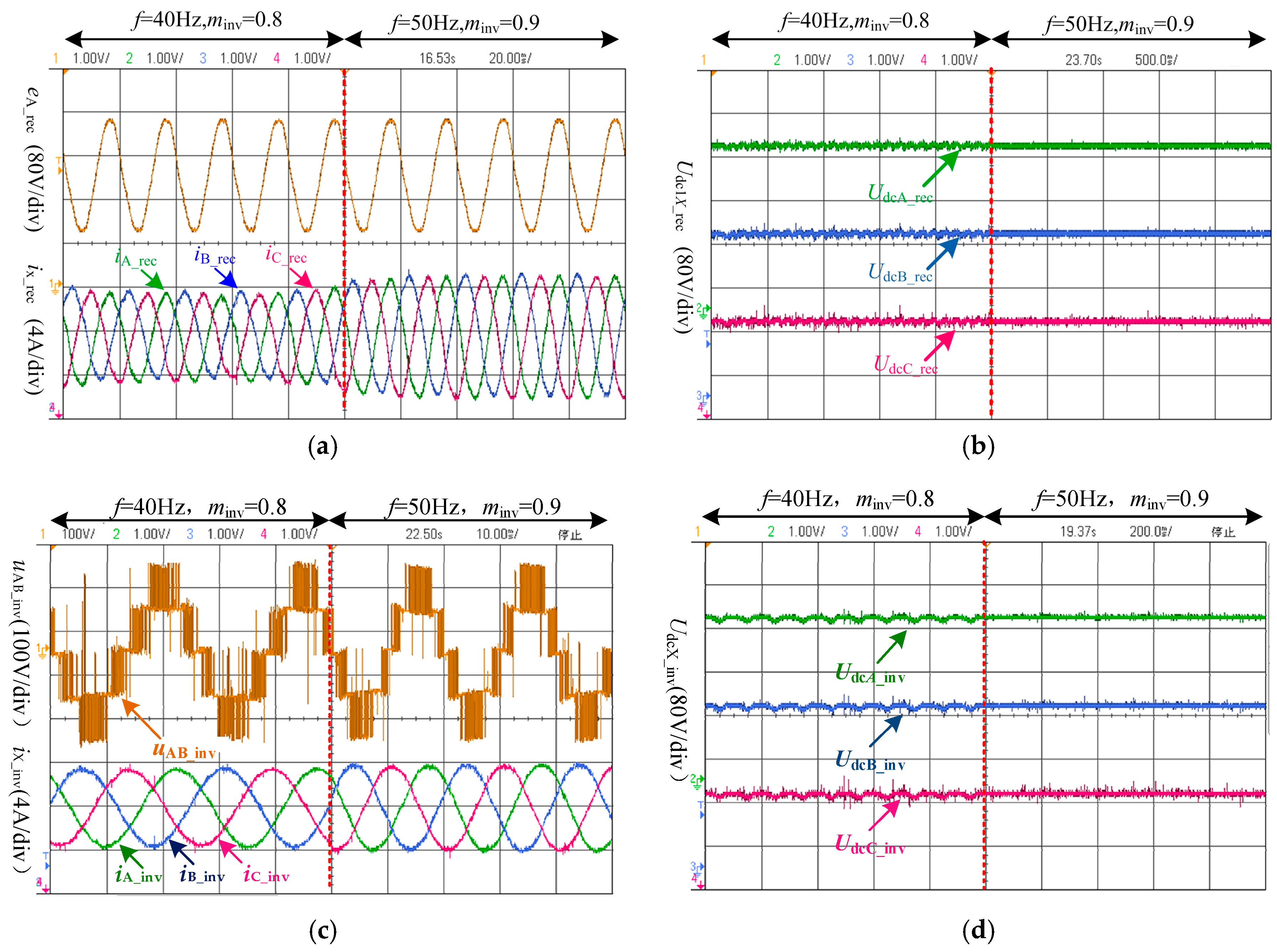
4.2. Experimental Results
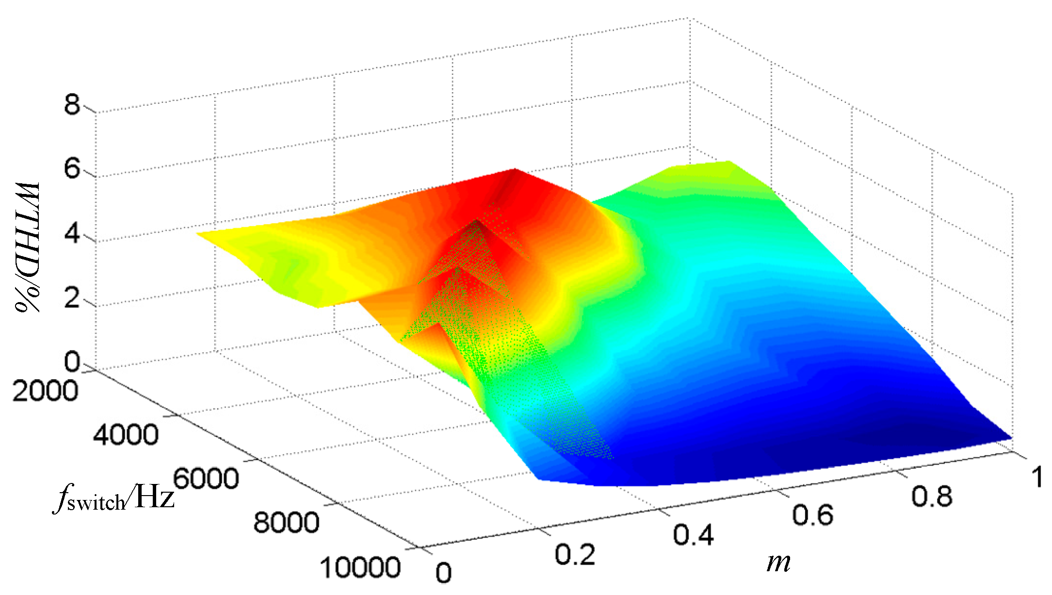
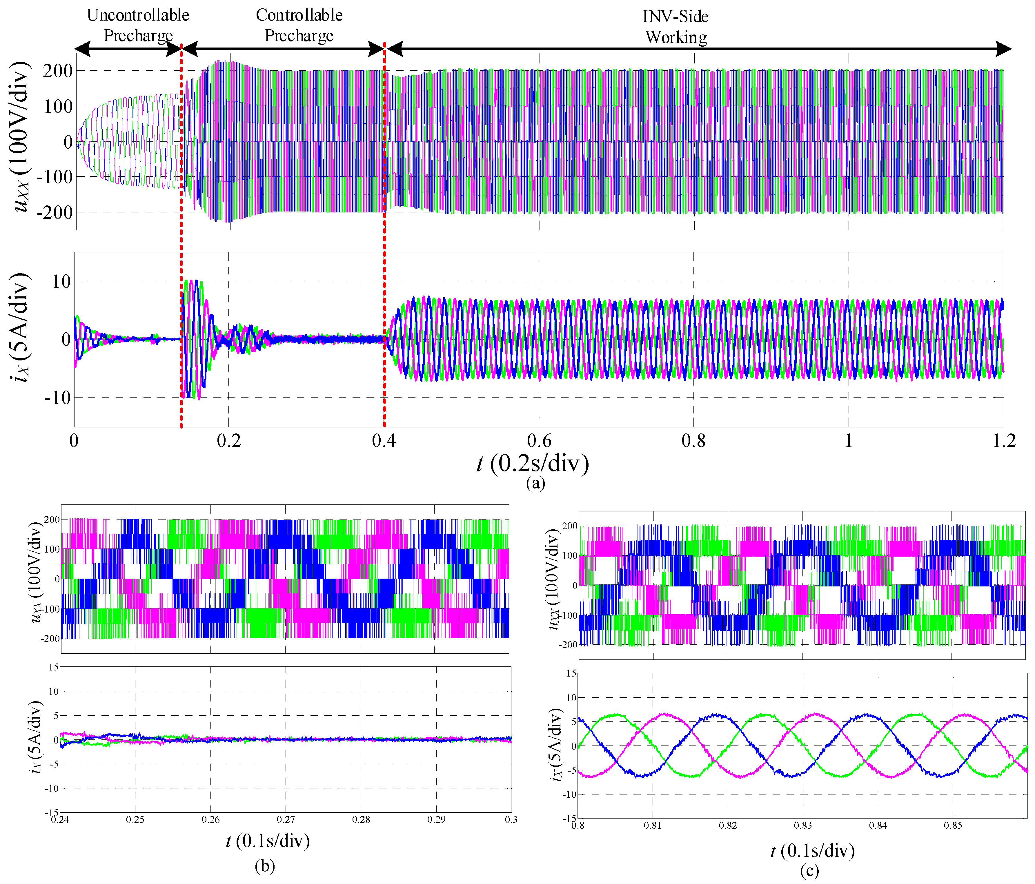
4.3. Simulation Results
4.4. Simulation Analysis of 5/3 Level Voltage Source Converter
5. Conclusions
Author Contributions
Funding
Conflicts of Interest
References
- Nguyen, L.V.; Tran, H.D.; Johnson, T.T. Virtual prototyping for distributed control of a fault-tolerant modular multilevel inverter for photovoltaics. IEEE Trans. Energy Convers. 2014, 29, 841–850. [Google Scholar] [CrossRef]
- Alishah, R.S.; Hosseini, S.H.; Babaei, E.; Sabahi, M. A New General Multilevel Converter Topology Based on Cascaded Connection of Submultilevel Units With Reduced Switching Components, DC Sources, and Blocked Voltage by Switches. IEEE Trans. Ind. Electron. 2016, 63, 7157–7164. [Google Scholar] [CrossRef]
- Buccella, C.; Cecati, C.; Cimoroni, M.G.; Razi, K. Analytical method for pattern generation in five-level cascaded H-bridge inverter using selective harmonic elimination. IEEE Trans. Ind. Electron. 2014, 61, 5811–5819. [Google Scholar] [CrossRef]
- Zamiri, E.; Vosoughi, N.; Hosseini, S.H.; Barzegarkhoo, R.; Sabahi, M. A New Cascaded Switched-Capacitor Multilevel Inverter Based on Improved Series–Parallel Conversion with Less Number of Components. IEEE Trans. Ind. Electron. 2016, 63, 3582–3594. [Google Scholar] [CrossRef]
- Tolbert, L.M.; Fang, Z.P.; Thomas, G.H. Multilevel Converters for Large Electric Drives. IEEE Trans. Ind. Appl. 1999, 35, 36–44. [Google Scholar] [CrossRef]
- Teymour, H.R.; Sutanto, D.; Muttaqi, K.M. Solar PV and Battery Storage Integration using a New Configuration of a Three-Level NPC Inverter With Advanced Control Strategy. IEEE Trans. Energy Convers. 2014, 29, 354–365. [Google Scholar]
- Pouresmaeil, E.; Montesinos-Miracle, D.; Gomis-Bellmunt, O. Control scheme of three-level NPC inverter for integration of renewable energy resources into AC grid. IEEE Syst. J. 2012, 6, 242–253. [Google Scholar] [CrossRef]
- Peng, F.Z.; Lai, J.S.; McKeever, J.W. A multilevel voltage-source inverter with separate DC sources for static var generation. IEEE Trans. Ind. Appl. 1996, 32, 1130–1138. [Google Scholar] [CrossRef]
- Pou, J.; Ceballos, S.; Knstantinou, G. Circulating current injection methods based on instantaneous information for the modular multilevel converter. IEEE Trans. Ind. Electron. 2015, 62, 777–788. [Google Scholar] [CrossRef]
- Meshram, P.M.; Borghate, V.B. A simplified nearest level control (NLC) voltage balancing method for modular multilevel converter (MMC). IEEE Trans. Power Electron. 2015, 30, 450–462. [Google Scholar] [CrossRef]
- Hatti, N.; Hasegawa, K.; Akagi, H. A 6.6-kV transformerless motor drive using a five-level diode-clamped PWM inverter for energy savings of pumps and blowers. IEEE Trans. Power Electron. 2009, 24, 796–803. [Google Scholar] [CrossRef]
- Ghias, A.M.Y.M.; Pou, J.; Agelidis, V.G.; Ciobotaru, M. Optimal switching transition-based voltage balancing method for flying capacitor multilevel converters. IEEE Trans. Power Electron. 2015, 30, 1804–1817. [Google Scholar] [CrossRef]
- Oikonomou, N.; Gutscher, C.; Karamanakos, P.; Kieferndorfand, F.D.; Geyer, T. Model predictive pulse pattern control for the five-level active neutral-point-clamped inverter. IEEE Trans. Ind. Appl. 2013, 49, 2583–2592. [Google Scholar] [CrossRef]
- Roshankumar, P.; Rajeevan, P.P.; Mathew, K.; Leon, J.I.; Franquelo, L.G. A five-level inverter topology with single-DC supply by cascading a flying capacitor inverter and an H-bridge. IEEE Trans. Power Electron. 2012, 27, 3505–3512. [Google Scholar] [CrossRef]
- Ooi, G.H.P.; Maswood, A.L.; Lim, Z. Five-level multiple-pole PWM AC-AC converters with reduced components count. IEEE Trans. Ind. Electron. 2015, 62, 4739–4748. [Google Scholar] [CrossRef]
- Narimani, M.; Wu, B.; Cheng, Z.; Zargari, N.R. A new nested neutral point-clamped (NNPC) converter for medium-voltage (MV) power conversion. IEEE Trans. Power Electron. 2014, 29, 6375–6382. [Google Scholar] [CrossRef]
- Cortes, P.; Wilson, A.; Kouro, S.; Rodriguez, J.; Abu-Rub, H. Model predictive control of multilevel cascaded H-bridge inverters. IEEE Trans. Ind. Electron. 2010, 57, 2691–2699. [Google Scholar] [CrossRef]
- Kouro, S.; Malinowski, M.; Gopakumar, K.; Pou, J.; Franquelo, L.G.; Wu, B.; Rodriguez, J.; Perez, M.A.; Leon, J.I. Recent Advances and Industrial Applications of Multilevel Converters. IEEE Trans. Ind. Electron. 2010, 57, 2553–2580. [Google Scholar] [CrossRef]
- Veenstra, M.; Rufer, A. Hybrid Cascaded Control of a Hybrid Asymmetric Multilevel Inverter for Competitive Medium-Voltage Industrial Drives. IEEE Trans. Ind. Appl. 2005, 41, 655–664. [Google Scholar] [CrossRef]
- Venugopal, J.; Subarnan, G.M. Hybrid cascaded MLI topology using ternary voltage progression technique with multicarrier strategy. J. Electr. Eng. Technol. 2015, 10, 1610–1620. [Google Scholar] [CrossRef]
- Miranbeigi, M.; Iman-Eini, H.; Asoodar, M. A new switching strategy for transformer-less back-to-back cascaded H-bridge multilevel converter. IET Power Electron. 2014, 7, 1868–1877. [Google Scholar] [CrossRef]
- Kongnun, W.; Sangswang, A.; Chotigo, S. Design of a cascaded H-bridge converter for insulation testing. In Proceedings of the IEEE International Symposium on Industrial Electronics, Seoul, Korea, 5–8 July 2009; pp. 859–863. [Google Scholar]
- Blahnik, V.; Peroutka, Z.; Talla, J. Control of cascaded H-bridge active rectifier providing active voltage balancing. In Proceedings of the 40th Annual Conference of the IEEE Industrial Electronics Society, IECON 2014, Dallas, TX, USA, October–1 November 2015; pp. 4589–4594. [Google Scholar]
- Islam, M.R.; Guo, Y.; Zhu, J.G. Performance and cost Comparison of NPC, FC and SCHB Multilevel Converter Topologies for High-voltage Applications. In Proceedings of the International Conference on Electrical Machines and Systems, Beijing, China, 20–23 August 2011; pp. 1–6. [Google Scholar]
- Fazel, S.S.; Bernet, S.; Krug, D.; Jalili, K. Design and Comparison of 4-kv Neutral-point-clamped, Flying-capacitor, and Series-connected H-bridge Multilevel Converters. IEEE Tran. Ind. Appl. 2007, 43, 1032–1040. [Google Scholar] [CrossRef]
- Minambres-Marcos, V.; Guerrero-Martinez, M.A.; Romero-Cadaval, E.; Milanes-Montero, M.I. Generic Losses Model for Traditional Inverters and Neutral Point Clamped Inverters. Electron. Electr. Eng. 2014, 20, 84–88. [Google Scholar] [CrossRef]
- Ye, Z.B.; Xu, Y.M.; Li, F.; Deng, X.M.; Zhang, Y.Z. Simplified PWM Strategy for Neutral-Point-Clamped (NPC) Three-Level Converter. J. Power Electron. 2014, 14, 519–530. [Google Scholar] [CrossRef]


| Rectifier State | S1 S2 | Inverter State | S3 S4 S5 |
|---|---|---|---|
| P | S1S2 = 10 | P | S3 = 1, S4 = S5 or S3 = 0, S4 = 0, S5 = 1 |
| O | S3 = 0, S4 = S5 or S3 = 1, S4 = 1, S5 = 0 | ||
| N | S3 = 0, S4 = 1, S5 = 0 | ||
| O | S1 = S2 | P | S3 = S2, S4 = 0, S5 = 1 or S2 = 0, S3 = 1, S4 = S5 |
| O | S2 = S3, S4 = S5 or S2 = 1, S3 = 0,S4 = 0, S5 = 1 or S2 = 0, S3 = 1, S4 = 1, S5 = 0 | ||
| N | S2 = S3, S4 = 1, S5 = 0 or S2 = 1, S3 = 0, S4 = S5 | ||
| N | S1S2 = 01 | P | S3 = 1, S4 = 0, S5 = 1 |
| O | S3 = 1, S4 = S5 or S3 = 0, S4 = 0, S5 = 1 | ||
| N | S3 = 1, S4 = 1, S5 = 0 or S3 = 0, S4 = S5 |
| Level | 3L | 5L | ||||||
|---|---|---|---|---|---|---|---|---|
| Topology | NPC | FC | CHB | CMC | NPC | FC | CHB | CMC |
| Rated device voltage (IGBT) | 4.5 kV | 4.5 kV | 4.5 kV | 4.5 kV | 3.3 kV | 3.3 kV | 3.3 kV | 3.3 kV |
| Rated device current (IGBT) | 450 A | 450 A | 450 A | 450 A | 450 A | 450 A | 450 A | 450 A |
| IGBTs | 24 | 24 | 24 | 30 | 48 | 48 | 48 | 54 |
| Diodes | 12 | --- | --- | --- | 36 | --- | --- | --- |
| Capacitors | 2 + 0 | 2 + 6 | 3 + 0 | 6 + 0 | 4 + 0 | 4 + 18 | 6 + 0 | 12 + 0 |
| Total Components | 38 | 32 | 23 | 36 | 88 | 70 | 54 | 66 |
| a1 | a2 | utemp1, utemp2 | uz_rec |
|---|---|---|---|
| >0 | >0 | utemp1 > utemp2 | utemp1 |
| utemp1 ≤ utemp2 | utemp2 | ||
| <0 | utemp1 > utemp2 | 0 | |
| utemp1 ≤ utemp2 | (utemp1 + utemp2)/2 | ||
| <0 | >0 | utemp1 > utemp2 | (utemp1 + utemp2)/2 |
| utemp1 ≤ utemp2 | 0 | ||
| <0 | utemp1 > utemp2 | utemp2 | |
| utemp1 ≤ utemp2 | utemp1 |
| Inverter State | iX_inv | S2 | Inverter Side I | Inverter Side II | Switch Combinations | Charge State |
|---|---|---|---|---|---|---|
| P | >0 | 1 | O | P | S3S4S5 = 101 | D |
| 0 | O | P | S3S4S5 = 001 | D | ||
| P | O | S3 = 1, S4 = S5 | K | |||
| ≤0 | 1 | O | P | S3S4S5 = 101 | C | |
| 0 | P | O | S3 = 1, S4 = S5 | K | ||
| O | P | S3S4S5 = 001 | C | |||
| O | >0 | 1 | N | P | S3S4S5 = 001 | D |
| O | O | S3 = 1, S4 = S5 | K | |||
| 0 | O | O | S3 = 0, S4 = S5 | K | ||
| P | N | S3S4S5 = 110 | C | |||
| ≤0 | 1 | O | O | S3 = 1, S4 = S5 | K | |
| N | P | S3S4S5 = 001 | C | |||
| 0 | P | N | S3S4S5 = 110 | D | ||
| O | O | S3 = 0, S4 = S5 | K | |||
| N | >0 | 1 | N | O | S3 = 0, S4 = S5 | K |
| O | N | S3S4S5 = 110 | C | |||
| 0 | O | N | S3S4S5 = 010 | C | ||
| 1 | O | N | S3S4S5 = 110 | D | ||
| N | O | S3 = 0, S4 = S5 | K | |||
| 0 | O | N | S3S4S5 = 010 | D |
| u*A_rec − uz_rec | u*A_inv − uz | UdcA_inv | iA_inv | tS1 | tS2 | tS3 | tS4 | tS5 |
|---|---|---|---|---|---|---|---|---|
| >0 | >0 | UdcA_inv > Udcref_inv | >0 | TA_rec | 0 | 0 | 0 | TA_inv |
| ≤0 | TA_rec | 0 | Ts | Ts | TA_inv | |||
| UdcA_inv ≤ Udcref_inv | >0 | |||||||
| ≤0 | TA_rec | 0 | 0 | 0 | TA_inv | |||
| ≤0 | UdcA_inv > Udcref_inv | >0 | Ts | TA_rec | 0 | TA_rec | TA_inv | |
| ≤0 | TA_rec | 0 | TA_inv | Ts | 0 | |||
| UdcA_inv ≤ Udcref_inv | >0 | |||||||
| ≤0 | Ts | TA_rec | 0 | TA_rec | TA_inv | |||
| ≤0 | >0 | UdcA_inv > Udcref_inv | >0 | TA_rec | Ts | TA_inv | 0 | Ts |
| ≤0 | 0 | TA_rec | Ts | TA_rec | TA_inv | |||
| UdcA_inv ≤ Udcref_inv | >0 | |||||||
| ≤0 | TA_rec | Ts | TA_inv | 0 | Ts | |||
| ≤0 | UdcA_inv > Udcref_inv | >0 | TA_rec | Ts | 0 | 0 | TA_inv | |
| ≤0 | TA_rec | Ts | Ts | Ts | TA_inv | |||
| UdcA_inv ≤ Udcref_inv | >0 | |||||||
| ≤0 | TA_rec | Ts | 0 | 0 | TA_inv |
| Parameter | Value |
|---|---|
| Source voltage, eX_rec | 55 V |
| DC-link voltage | 100 V |
| DC-link capacitor | 1200 μF |
| Filter-inductive | 2.2 mH |
| Resistive-inductive load | 20 Ω, 2.2 mH |
| Switching frequency | 5 kHz |
© 2018 by the authors. Licensee MDPI, Basel, Switzerland. This article is an open access article distributed under the terms and conditions of the Creative Commons Attribution (CC BY) license (http://creativecommons.org/licenses/by/4.0/).
Share and Cite
Ye, Z.; Chen, A.; Mao, S.; Wang, T.; Yu, D.; Deng, X. A Novel Three-Level Voltage Source Converter for AC–DC–AC Conversion. Energies 2018, 11, 1147. https://doi.org/10.3390/en11051147
Ye Z, Chen A, Mao S, Wang T, Yu D, Deng X. A Novel Three-Level Voltage Source Converter for AC–DC–AC Conversion. Energies. 2018; 11(5):1147. https://doi.org/10.3390/en11051147
Chicago/Turabian StyleYe, Zongbin, Anni Chen, Shiqi Mao, Tingting Wang, Dongsheng Yu, and Xianming Deng. 2018. "A Novel Three-Level Voltage Source Converter for AC–DC–AC Conversion" Energies 11, no. 5: 1147. https://doi.org/10.3390/en11051147
APA StyleYe, Z., Chen, A., Mao, S., Wang, T., Yu, D., & Deng, X. (2018). A Novel Three-Level Voltage Source Converter for AC–DC–AC Conversion. Energies, 11(5), 1147. https://doi.org/10.3390/en11051147