Numerical Simulation of Flow and Heat Transfer in Structured Packed Beds with Smooth or Dimpled Spheres at Low Channel to Particle Diameter Ratio


Abstract
:1. Introduction
2. Computational Model and Method
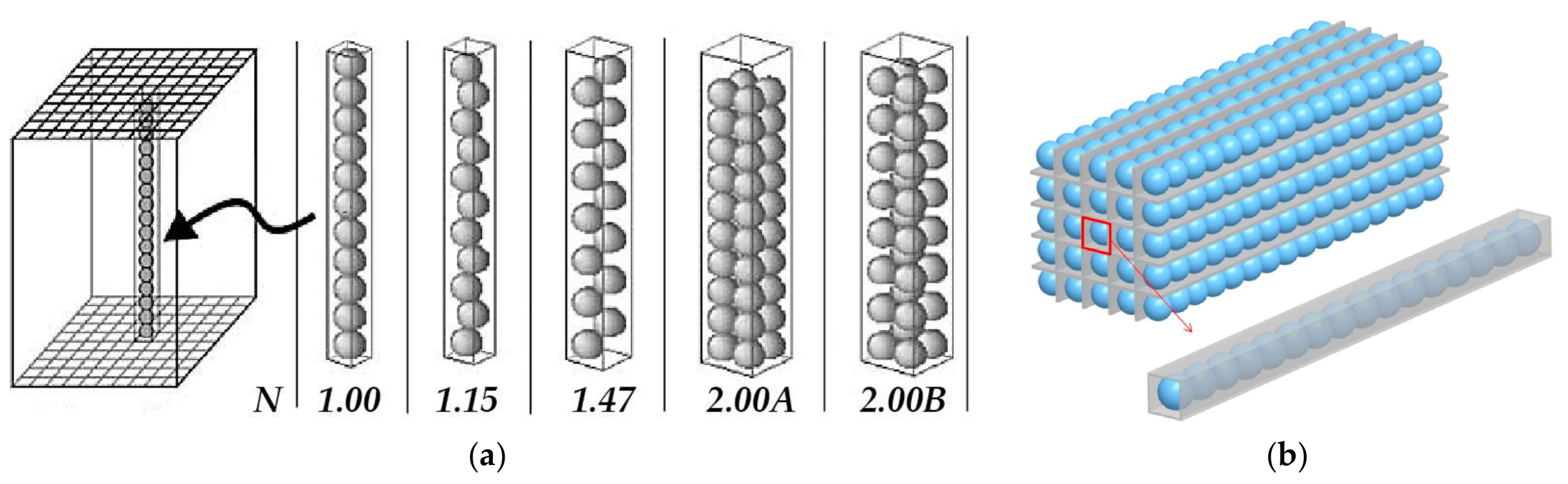
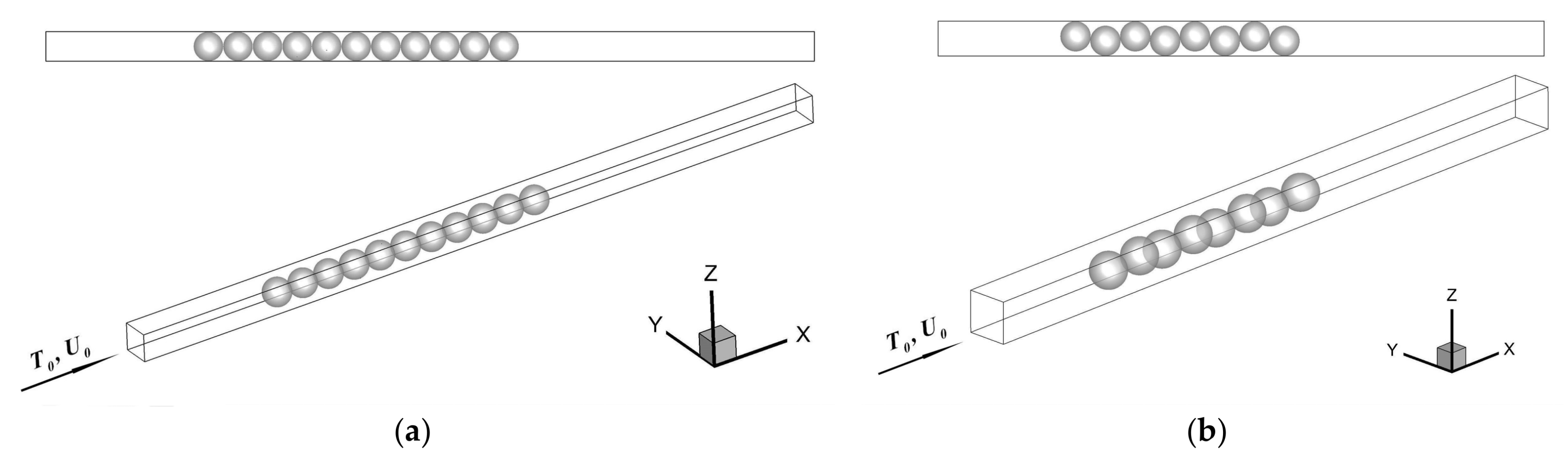
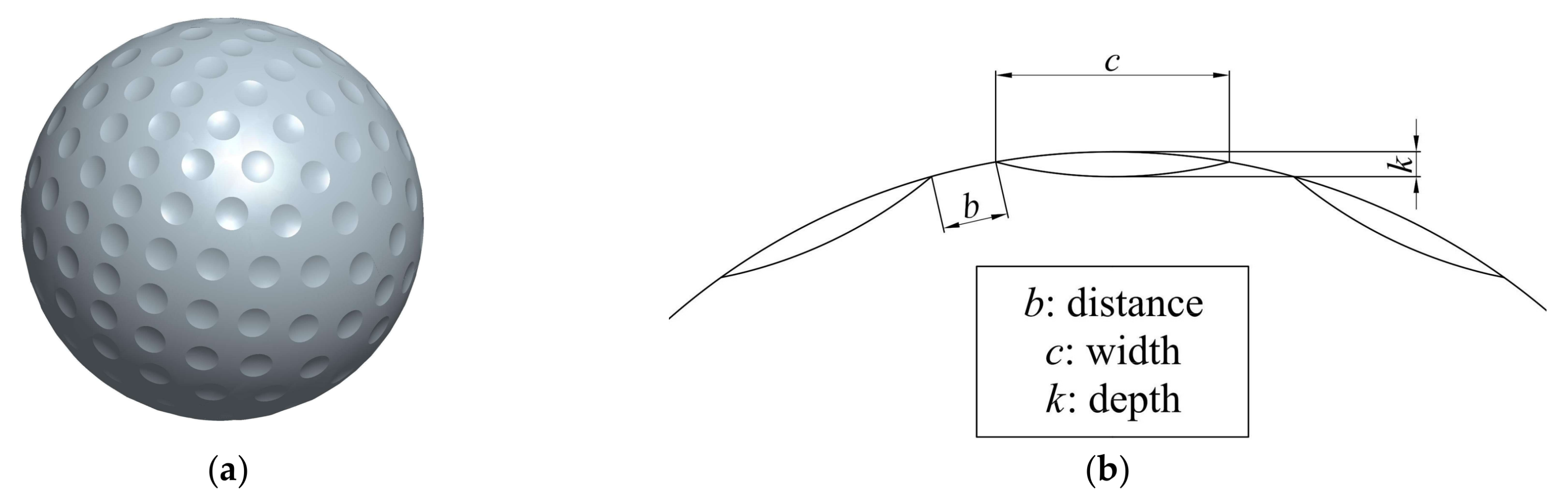
2.1. Physical Model
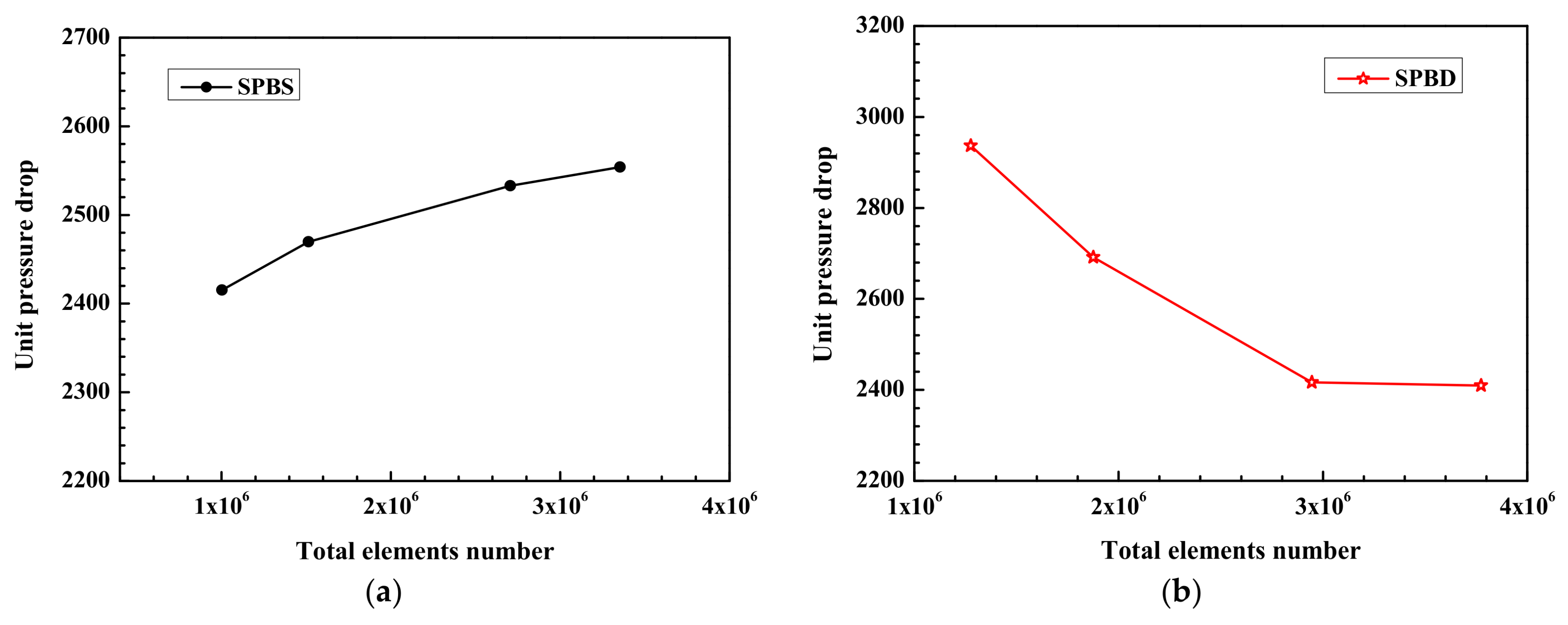
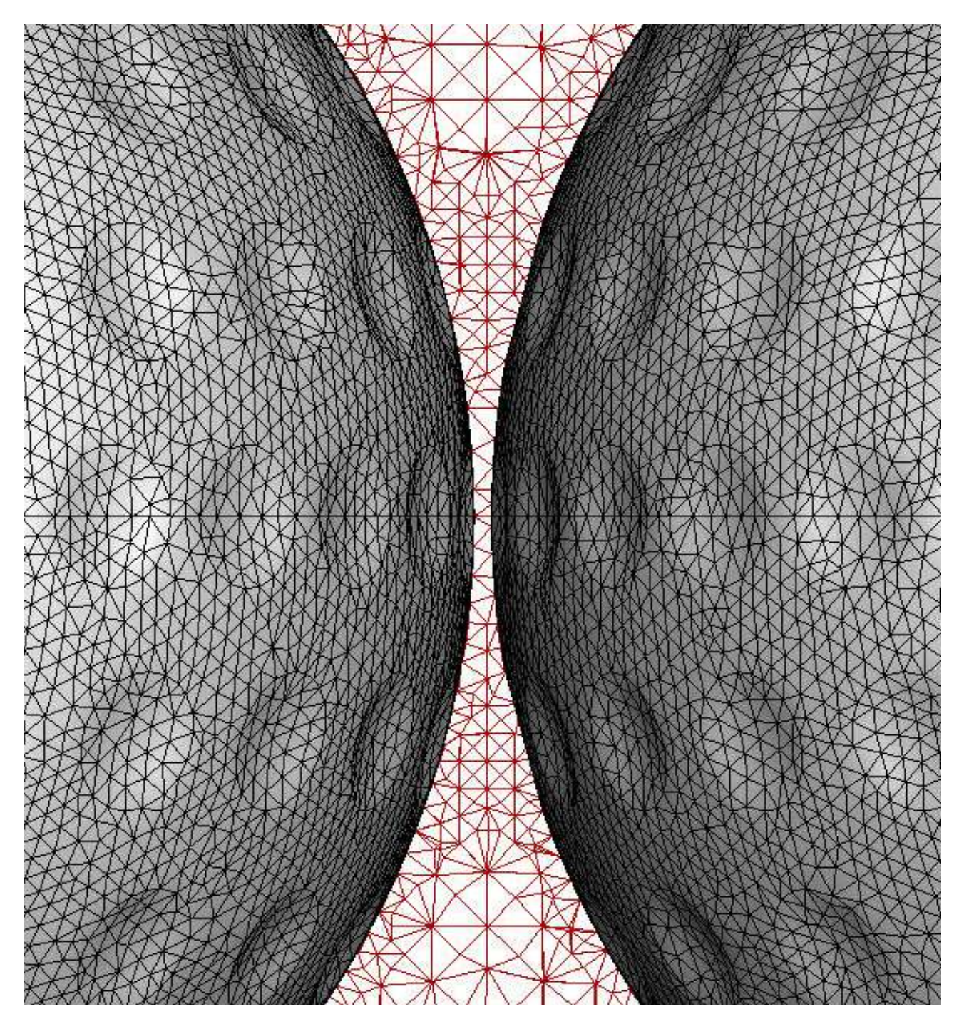
2.2. Computational Method
3. Results and Discussion
3.1. N = 1.00 Packing
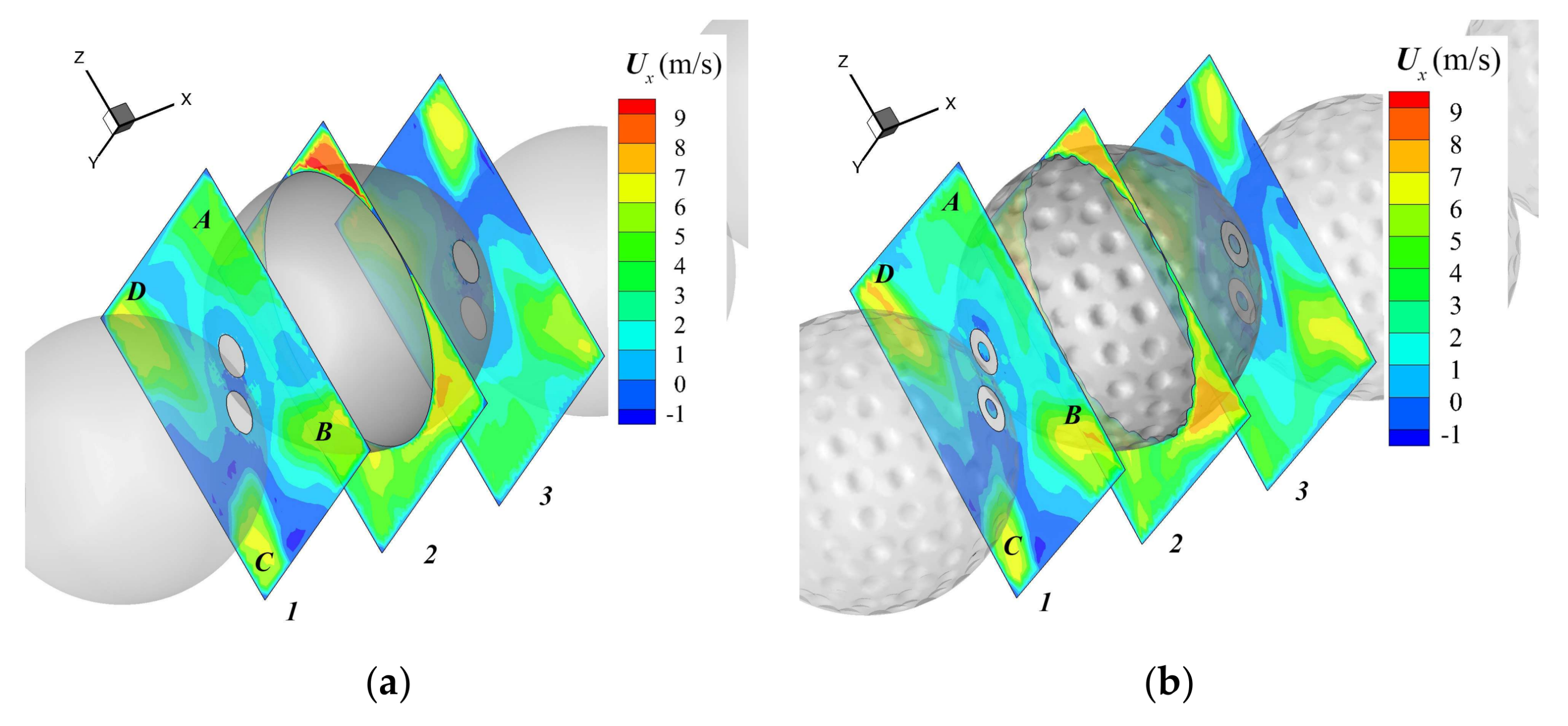
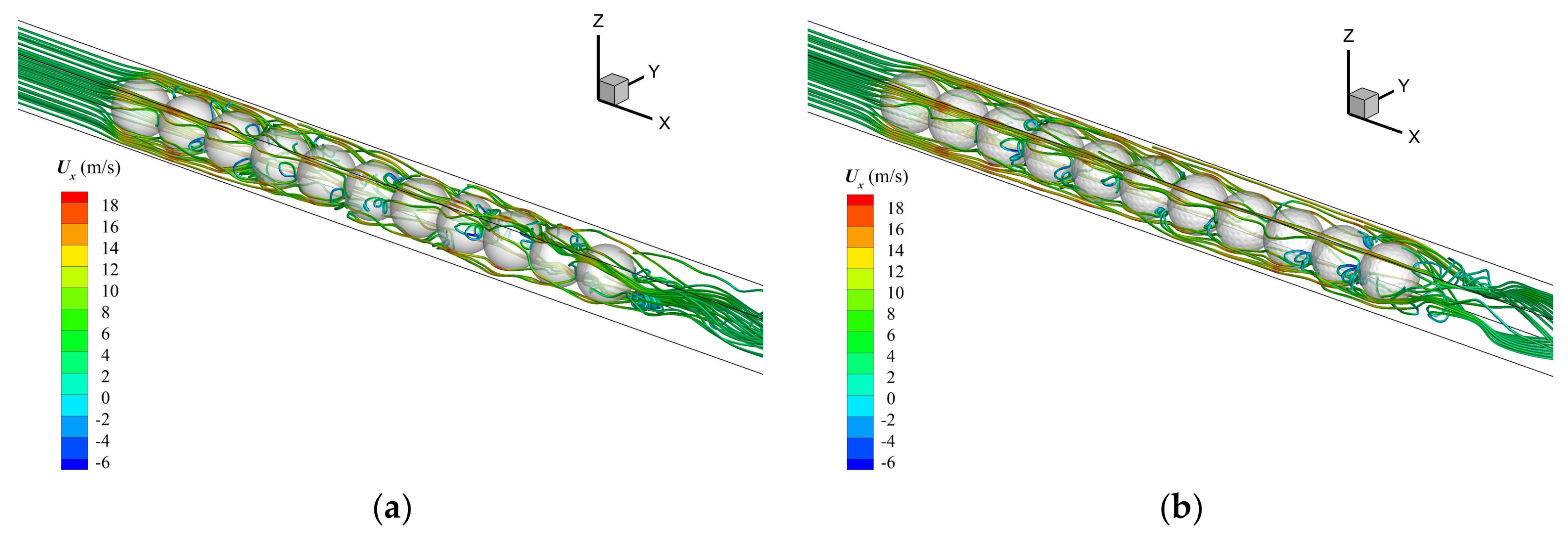
3.1.1. The Flow Characteristics
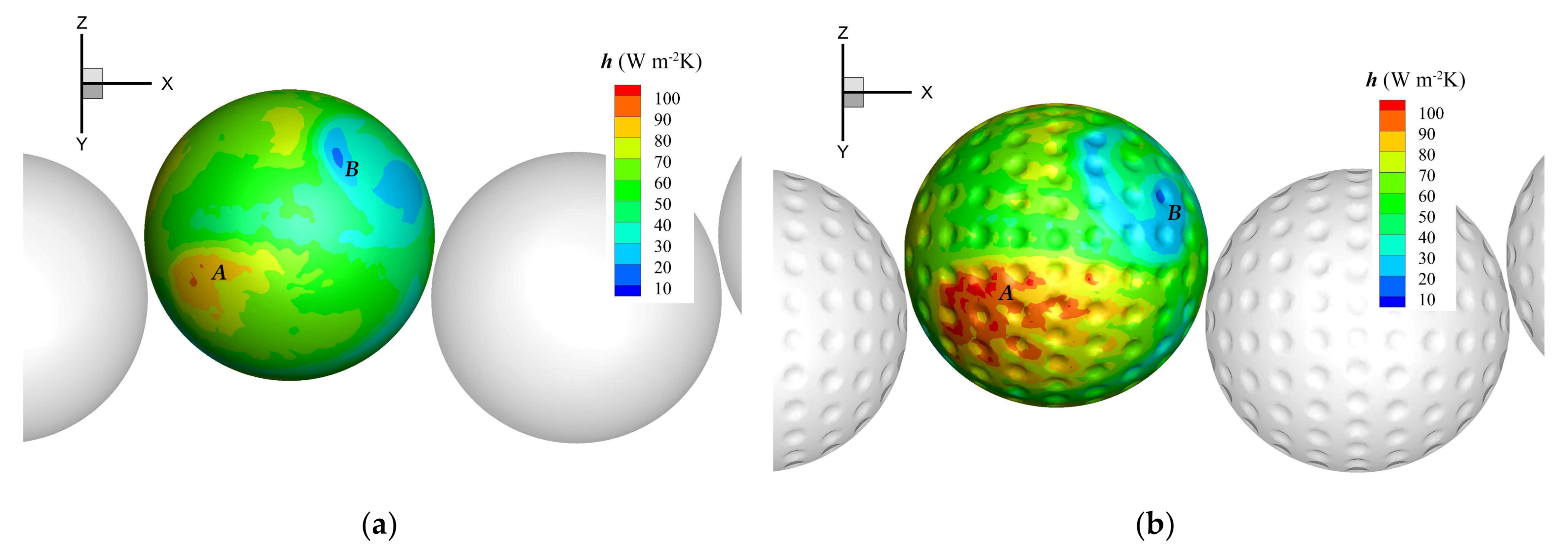
3.1.2. The Heat Transfer Characteristics
3.2. N = 1.15 Packing
3.2.1. The Flow Characteristics
3.2.2. The Heat Transfer Characteristics
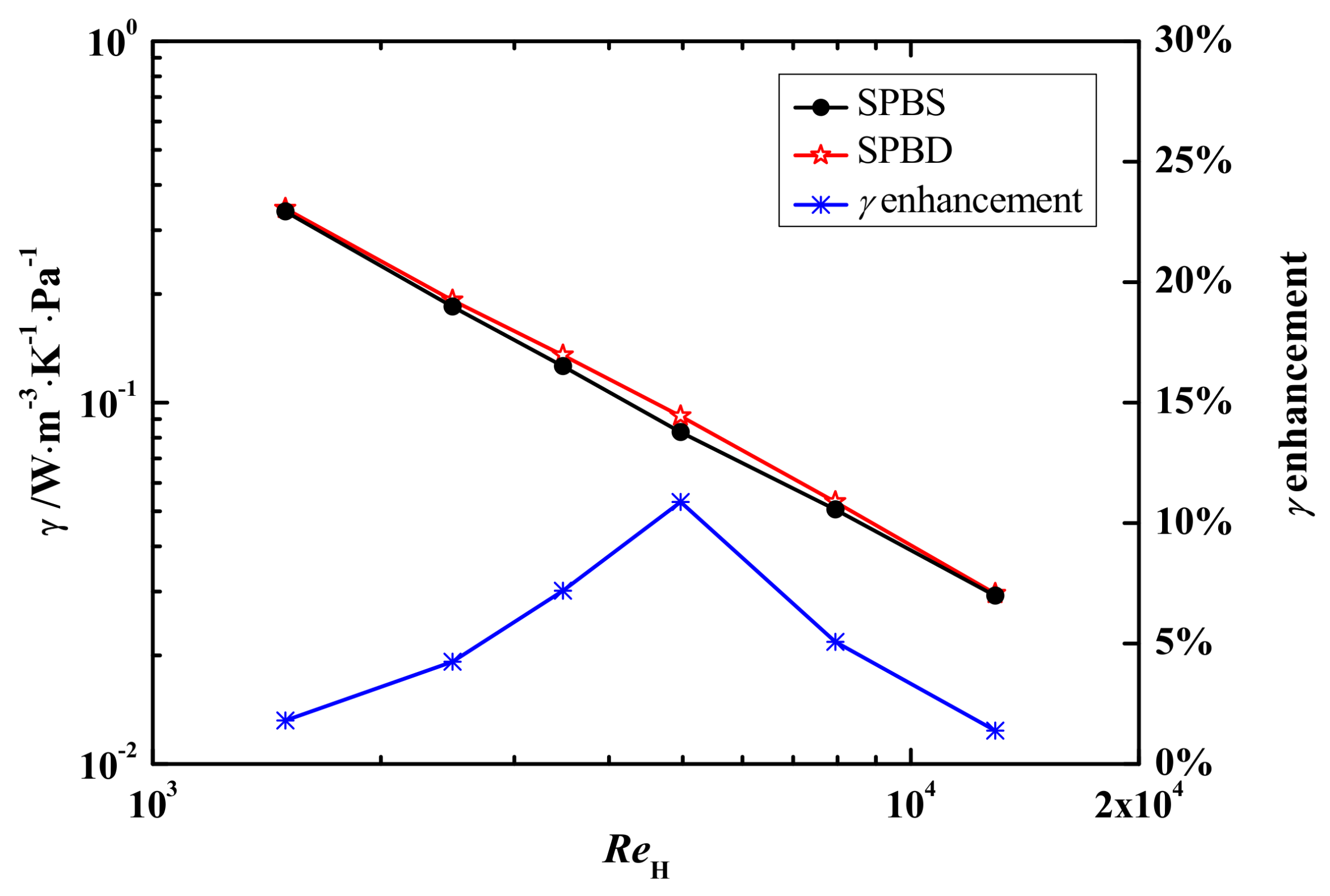
3.3. The Effect of Packing Configuration
4. Conclusions
Acknowledgments
Author Contributions
Conflicts of Interest
Nomenclature
| A | area (m2) |
| b | distance between dimples (m) |
| c | width of dimple (m) |
| d | diameter (m) |
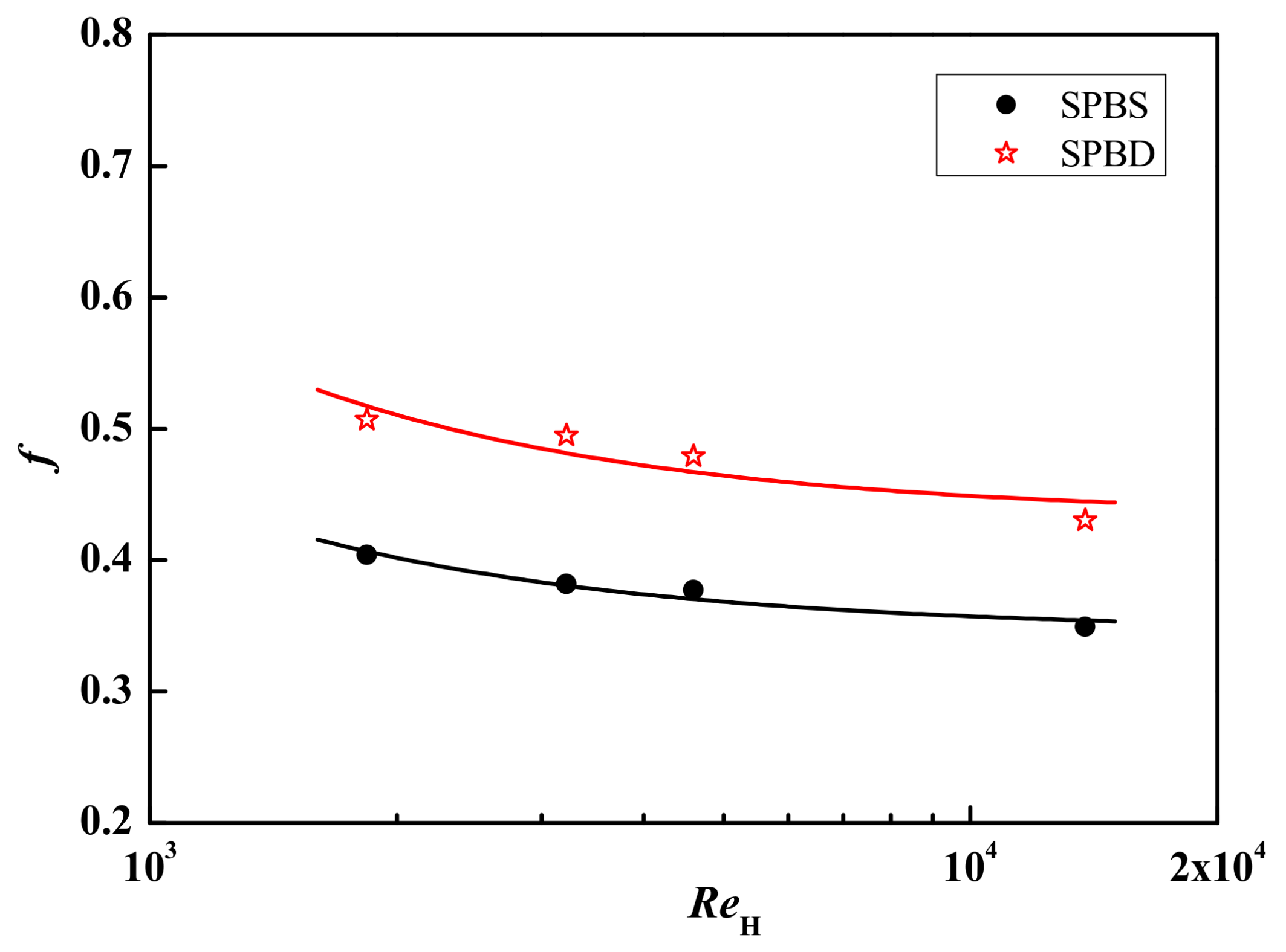
| f | friction factor |
| h | heat transfer coefficient (W∙m−2∙K) |
| H | widths of the square channel (m) |
| k | depth of dimple (m) |
| L | length of the square channel |
| N | channel to particle diameter ratio |
| ND | the number of dimples on the sphere |
| Nu | Nusselt number |
| Δp | pressure drop (Pa) |
| q | heat transfer rate (J∙s−1) |
| ReH | hydraulic Reynolds number |
| T | temperature (K) |
| U | velocity (m∙s−1) |
| V | volume (m3) |
| Greek letters | |
| ε | porosity |
| ρ | density (kg∙m−3) |
| μ | dynamic viscosity (kg∙m−1∙s−1) |
| λ | thermal conductivity (W∙m−1∙K−1) |
| γ | overall heat transfer efficiency (W∙m−3∙K−1∙Pa−1) |
| Subscripts | |
| 0 | initial state at inlet |
| f | fluid |
| i | interstitial |
| H | hydraulic |
| p | particle |
| w | wall |
References
- Ergun, S. Fluid flow through packed columns. Chem. Eng. Prog. 1952, 48, 89–94. [Google Scholar]
- Strangio, V.A.; Dautzenberg, F.M.; Calis, H.P.A.; Gupta, A. Fixed Catalytic Bed Reactor. International Patent Application PCT/US99/06242, 23 March 1998. [Google Scholar]
- Calis, H.P.A.; Nijenhuis, J.; Paikert, B.C.; Bleek, C.M.V.D. CFD modelling and experimental validation of pressure drop and flow profile in a novel structured catalytic reactor packing. Chem. Eng. Sci. 2001, 56, 1713–1720. [Google Scholar] [CrossRef]
- Romkes, S.J.P.; Dautzenberg, F.M.; Bleek, C.M.V.D.; Calis, H.P.A. CFD modelling and experimental validation of particle-to-fluid mass and heat transfer in a packed bed at very low channel to particle diameter ratio. Chem. Eng. J. 2003, 96, 3–13. [Google Scholar] [CrossRef]
- Palle, S.; Aliabadi, S. Direct simulation of structured wall bounded packed beds using hybrid fe/fv methods. Comput. Fluids 2013, 88, 730–742. [Google Scholar] [CrossRef]
- Lin, C.N.; Jang, J.Y.; Lai, Y.S. Two Dimensional Thermal-Hydraulic Analysis for a Packed Bed Regenerator Used in a Reheating Furnace. Energies 2016, 9, 995. [Google Scholar] [CrossRef]
- Yang, J.; Wang, Q.; Zeng, M.; Nakayama, A. Computational study of forced convective heat transfer in structured packed beds with spherical or ellipsoidal particles. Chem. Eng. Sci. 2010, 65, 726–738. [Google Scholar] [CrossRef]
- Wang, J.; Yang, J.; Cheng, Z.; Liu, Y.; Chen, Y.; Wang, Q. Experimental and numerical study on pressure drop and heat transfer performance of grille-sphere composite structured packed bed. Appl. Energ. 2017, in press. [Google Scholar] [CrossRef]
- Hu, Y.; Yang, J.; Wang, J.; Zhou, L.; Li, S.; Wang, Q. Numerical study of forced convective heat transfer in grille-sphere composite packed bed with Taguchi-CFD method. Chem. Eng. Trans. 2017, 61, 313–318. [Google Scholar]
- Jin, C.; Jeon, W.P.; Choi, H. Mechanism of drag reduction by dimples on a sphere. Phys. Fluids 2006, 18, 112. [Google Scholar] [CrossRef]
- Aoki, K.; Ohike, A.; Yamaguchi, K.; Nakayama, Y. Flying characteristics and flow pattern of a sphere with dimples. J. Visual-Japan 2003, 6, 67–76. [Google Scholar] [CrossRef]
- Smith, C.E.; Beratlis, N.; Balaras, E.; Squires, K.; Tsunoda, M. Numerical investigation of the flow over a golf ball in the subcritical and supercritical regimes. Int. J. Heat Fluid Flow 2010, 31, 262–273. [Google Scholar] [CrossRef]
- Burgess, N.K.; Ligrani, P.M. Effects of Dimple Depth on Channel Nusselt Numbers and Friction Factors. J. Heat Trans.-T. ASME 2005, 127, 839–847. [Google Scholar] [CrossRef]
- Samad, A.; Lee, K.D.; Kim, K.Y. Shape Optimization of a Dimpled Channel to Enhance Heat Transfer Using a Weighted-Average Surrogate Model. Heat Transf. Eng. 2010, 31, 1114–1124. [Google Scholar] [CrossRef]
- Kim, S.M.; Jo, J.H.; Lee, Y.E.; Yoo, Y.S. Comparative Study of Shell and Helically-Coiled Tube Heat Exchangers with Various Dimple Arrangements in Condensers for Odor Control in a Pyrolysis System. Energies 2016, 9, 1027. [Google Scholar] [CrossRef]
- Crawford, C.W.; Plumb, O.A. The influence of surface roughness on resistance to flow through packed beds. J. Fluid Eng.-T. ASME 1986, 108, 343. [Google Scholar] [CrossRef]
- Yang, J.; Zhou, L.; Hu, Y.; Li, S.; Wang, Q. Numerical study of forced convective heat transfer in structured packed beds of dimple-particles. Heat Transf. Eng. 2017, in press. [Google Scholar] [CrossRef]
- ANSYS Inc. ANSYS User and Theory Guide, ANSYS Fluent, Release 14.5; ANSYS Inc.: Cecil Township, PA, USA, 2012. [Google Scholar]


| ND | b (mm) | c (mm) | k (mm) |
|---|---|---|---|
| 184 | 2.043 | 3.528 | 0.338 |
| ReH | SPBS | SPBD | Unit Pressure Drop Reduction |
|---|---|---|---|
| 1504 | 114.0 | 106.4 | 6.63% |
| 2506 | 297.6 | 296.8 | 0.27% |
| 3509 | 544.7 | 540.9 | 0.68% |
| 5013 | 1066.8 | 987.6 | 7.42% |
| 8021 | 2554.0 | 2409.5 | 5.66% |
| 13,033 | 6388.8 | 6204.7 | 2.88% |
| ReH | SPBS | SPBD | Heat Transfer Enhancement |
|---|---|---|---|
| 1504 | 68.2 | 64.9 | −4.94% |
| 2506 | 97.1 | 100.9 | 3.96% |
| 3509 | 121.6 | 129.5 | 6.46% |
| 5013 | 156.4 | 160.5 | 2.65% |
| 8021 | 228.8 | 226.8 | −0.87% |
| 13,033 | 330.3 | 325.2 | −1.54% |
| ReH | SPBS | SPBD | Unit Pressure Drop Reduction |
|---|---|---|---|
| 1840 | 31.4 | 39.5 | −25.45% |
| 3219 | 91.0 | 117.9 | −29.62% |
| 4599 | 183.4 | 232.9 | −26.98% |
| 13,797 | 1528.0 | 1883.0 | −23.23% |
| ReH | Smooth Spheres Packed Bed | Dimpled Spheres Packed Bed | Heat Transfer Enhancement |
|---|---|---|---|
| 1840 | 47.6 | 52.4 | 10.09% |
| 3219 | 72.1 | 81.1 | 12.51% |
| 4599 | 93.1 | 105.6 | 13.36% |
| 13,797 | 208.0 | 217.5 | 4.56% |
© 2018 by the authors. Licensee MDPI, Basel, Switzerland. This article is an open access article distributed under the terms and conditions of the Creative Commons Attribution (CC BY) license (http://creativecommons.org/licenses/by/4.0/).
Share and Cite
Li, S.; Zhou, L.; Yang, J.; Wang, Q. Numerical Simulation of Flow and Heat Transfer in Structured Packed Beds with Smooth or Dimpled Spheres at Low Channel to Particle Diameter Ratio. Energies 2018, 11, 937. https://doi.org/10.3390/en11040937
Li S, Zhou L, Yang J, Wang Q. Numerical Simulation of Flow and Heat Transfer in Structured Packed Beds with Smooth or Dimpled Spheres at Low Channel to Particle Diameter Ratio. Energies. 2018; 11(4):937. https://doi.org/10.3390/en11040937
Chicago/Turabian StyleLi, Shiyang, Lang Zhou, Jian Yang, and Qiuwang Wang. 2018. "Numerical Simulation of Flow and Heat Transfer in Structured Packed Beds with Smooth or Dimpled Spheres at Low Channel to Particle Diameter Ratio" Energies 11, no. 4: 937. https://doi.org/10.3390/en11040937
APA StyleLi, S., Zhou, L., Yang, J., & Wang, Q. (2018). Numerical Simulation of Flow and Heat Transfer in Structured Packed Beds with Smooth or Dimpled Spheres at Low Channel to Particle Diameter Ratio. Energies, 11(4), 937. https://doi.org/10.3390/en11040937