Abstract
Photovoltaic cluster power generation can improve the power generation efficiency of photovoltaic power plants, but the photovoltaic cluster inverter will produce resonance after the grid, affecting the safe and stable operation of power systems. In order to ensure the reliability of power supply, the resonant generation mechanism of photovoltaic cluster system is studied in this paper, and the resonant characteristics are analyzed, the control strategy of RC-type global resonance suppression and Thyristor Switching RC (TSRC) circuit are proposed, to suppress the resonance of the photovoltaic cluster system. The effectiveness of the control method is verified through simulation and experiment. The experimental results show that the resonance can be effectively suppressed, and the photovoltaic cluster system can be safely and stably connected to the power grid to ensure the reliability of power supply.
1. Introduction
Photovoltaic power generation system usually adopts the mode that multiple inverters operate in parallel to conduct grid connection [1], so as to ensure the power generation efficiency of the photovoltaic power station. However, connecting a large number of inverter clusters to the power grid will cause the system to resonate, and then affecting the stability of the power system and the power quality of the power grid.
A large amount of research has been carried out by scholars for the problem of resonant suppression of grid-connected photovoltaic inverter. In [2], proposing a modeling and analysis method based on the current separation scheme, root locus in the discrete z-domain is used to analyze the resonance current appearing between the paralleled inverters, depending on current distribution and resonance characteristics. However, no effective suppression method is given. An active harmonic wave conductance method is proposed in [3]. The harmonic current of the inverter is suppressed by paralleling conductance on each inverter to suppress the system resonance. However, only a single inverter system was validated, with Gaussian white Noise instead of harmonic source to simulate the inverter resonance, while did not build a whole photovoltaic cluster system to verify the control method. In [4], proposing a virtual complex impedance method to suppress the impact of system circulating currents and high-frequency resonance among parallel inverters, and an experimental verification was carried out. Although this method is effective, it is necessary to change the structure of each inverter in the grid-connected inverter cluster system. As the number of inverters increase, the control becomes more complicated. In summary, most of the methods for suppressing the resonance of the photovoltaic cluster inverter system need to change the control structure of each inverter, which is not easy to achieve in practical applications.
Therefore, this paper analyzes the structure of photovoltaic grid-connected systems, and derives the resonance mechanism and resonance characteristics of grid-connected inverter cluster systems based on transfer function and frequency domain method. The concept of global resonance suppression is introduced, the resonance suppression device is added only at the Point of Common Coupling (PCC), which it is not necessary to change the control structure of each inverter. Then, the RC-type global resonance suppression and Thyristor Switching RC circuit (TSRC) resonance suppression methods are proposed. Finally, the model of the grid-connected system of the photovoltaic cluster is built, and the effect of the resonance suppression is verified through simulation and experiment.
2. Structure of PV Cluster Grid-Connected System
The photovoltaic cluster inverter system is composed of a number of photovoltaic grid-connected systems connected in parallel, and the output current of multiple inverters will flow into the power grid after the convergence of Point of Common Coupling (PCC) [5,6,7]. The principle of the photovoltaic inverter cluster system is shown in Figure 1.
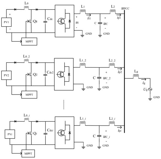
Figure 1.
Photovoltaic inverter cluster system schematic diagram.
In Figure 1, each set of the photovoltaic grid-connected system consists of four parts: photovoltaic power supply, inverter, LCL filter and power grid. L1, L2 are the inverter-side filter inductance and grid-side filter inductance, respectively. il1, ip1 are the current through L1 side and L2 side, respectively. ip2 is the influence of the second inverter connected in parallel to the first inverter grid-side current. C is the filter capacitor and uc is the voltage across C. Lg is the equivalent impedance of the power grid, Ug, ig are the power grid voltage and the grid current. upcc is the line voltage of Point of Common Coupling for the system.
3. Resonance Mechanism and Characteristic Analysis of Inverter Cluster Grid-Connected
3.1. Resonance Mechanism of Inverter Cluster Grid-Connected
Taking two inverters as an example to analyze the mechanism of resonance generation, the control block diagram is shown in Figure 2.
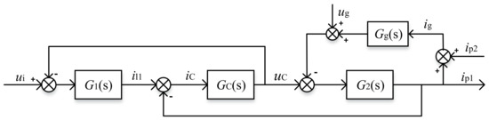
Figure 2.
Equivalent block diagram of LCL inverter grid-connected.
The transfer function is:
where
Let , Equation (2) is changed into:
According to Equation (3), it is found that there are two resonance points in the system:
where f1 is the resonance frequency of the LCL inverter itself, and f2 is the resonance frequency produced by the inverter cluster grid-connected.
3.2. Analysis of Resonance Characteristics of Inverter Cluster Grid-Connected
Further analysis of n inverters grid-connected resonance characteristics, the transfer function is:
where .
The resonance frequency of n inverters grid-connected is as follows:
The multi-inverter grid-connected frequency characteristic curve is shown in Figure 3, the system simulation parameters as shown in Table 1, and the peak value of each resonance point is shown in Table 2.
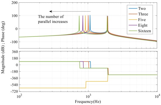
Figure 3.
Multiple parallel inverters frequency characteristic curve.

Table 1.
Simulation parameters of photovoltaic grid-connected system.
Table 2.
Resonance peak value of multiple parallel inverters in grid-connected.
As can be seen from Figure 3 and Table 2, multi-inverter cluster grid-connected will cause the system generate two resonance points, as the number of parallel inverters increases, the frequency of the resonance point generated by the grid-connected gradually decreases, and the frequency of the resonance point generated by the inverter itself remains unchanged.
The relationship between the resonance frequency of the inverter grid-connected and the number of parallel obtained by Equation (6), is shown in Figure 4.
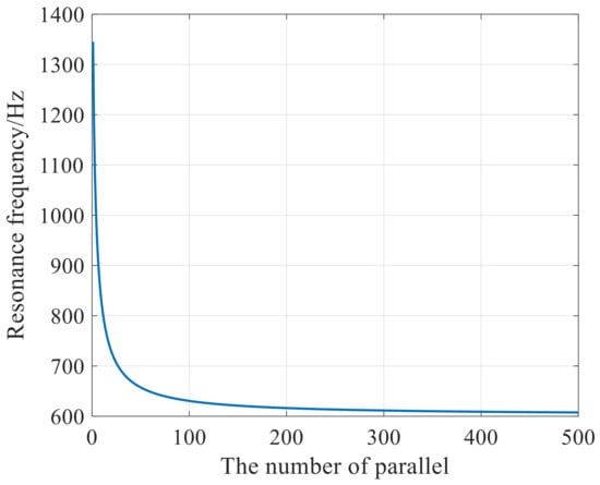
Figure 4.
Relationship between resonance frequency and the number of parallel.
Figure 4 shows that as the number of parallel inverters increases, the resonance frequency decreases. The reason is that after multiple inverters connected in parallel, the current flowing through the equivalent impedance of the grid is doubled, which is equivalent to doubling the impedance of the grid in each inverter equivalent circuit, so that the resonance frequency of the grid is reduced.
4. Resonance Suppression Measures
4.1. Single Inverter Grid-Connected Resonance Suppression Measures
There are two methods of resonance suppression for LCL inverter: passive damping method [8,9] and active damping method [10,11,12,13]. In the active damping method, actual resistance in the system is not introduced, using the control algorithm to increase the virtual resistance to achieve damping to suppress resonance; therefore, the system will not cause power loss.
A control strategy of inverter-side current feedback with capacitor current feedforward is presented in this paper to ensure the stability of the system while eliminating the grid-side current hysteresis, improving the control accuracy, and effectively suppressing the resonance peak produced by the LCL inverter; the control block diagram is shown in Figure 5.
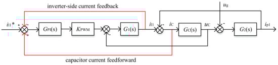
Figure 5.
Capacitor current feedforward and inverter-side current feedback control block diagram.
In Figure 5, the system input is i1*, the output is the grid-side current ip1. iC is the feedforward compensation to the system to eliminate the grid-side current hysteresis. GPI(s) is the PI controller, .
System transfer function is:
Substituting Equation (3) into Equation (9),
The system parameters are shown in Table 1; the frequency characteristic curve and the root locus diagram of Equation (8) is shown in Figure 6.
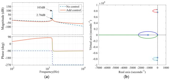
Figure 6.
(a) Capacitor current feedforward and inverter-side current feedback control frequency characteristic curve; (b) Root locus.
In Figure 6a, before and after the control strategy is added, the peak value of the current resonance point decreases from 103 dB to −2.78 dB, indicating that the capacitor current feedforward and inverter-side current feedback control strategy can effectively suppress the resonance. In Figure 6b, the root locus of the system is all distributed in the left half plane of the complex plane, which proves that this control method can ensure the stable operation of the system.
4.2. Multi-Inverter Grid-Connected Resonance Suppression Measures
For the resonance of multiple cluster inverters grid-connected, most of the researches are to change the control structure of each inverter. However, as the number of inverter clusters increases, the control system will become complicated. In this paper, global resonance suppression control strategy is adopted [14].
Global resonance suppression means that the resonance suppression device is added only at the PCC, so that even if a large number of inverters are clustered, it is not necessary to change the structure of each inverter, which is convenient and does not affect the original operation mode of inverters. There are three methods: R-type global resonance suppression, RC-type global resonance suppression, active global resonance suppression [15,16,17]. The R-type global resonance suppression paralleled the resistance directly at the PCC, which will bring a great power loss to the system. Active global resonance suppression is adding the active dampers at the PCC through power electronic devices. Although this method does not bring passive damping losses to the system, the control structure is complex and will cause system instability. In practical engineering, the power level of the power electronic devices is required to be high and the cost will be high because of the large power of the photovoltaic cluster inverters system.
Therefore, RC-type global resonance suppression method is adopted in this paper to eliminate the resonance generated by grid-connected inverter cluster. In this method, the RC circuit is paralleled at the PCC. The function of the resistor is to increase the system damping, reduce the resonance peak caused by the grid current harmonics, and the role of the capacitance is to make the damping resistor only act at the frequency of the resonance point, which reduces the system loss in power frequency. The principle of the RC resonance suppression circuit is shown in Figure 7.
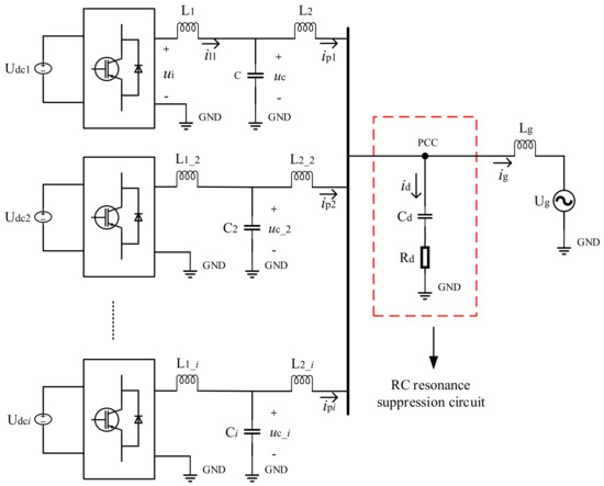
Figure 7.
RC resonance suppression circuit schematic diagram.
In Figure 7, Rd increases the system damping and reduces the resonance peak caused by the harmonics of the grid current, thus suppressing the resonance. Cd keeps the damping resistor working only at the resonance frequency, and reduces the system loss in power frequency.
From Equation (6), the resonance frequency of the circuit is:
It is known from Equation (9):
As can be seen from Figure 7:
Equation (11) transformed by Laplace:
System control block diagram shown in Figure 8.
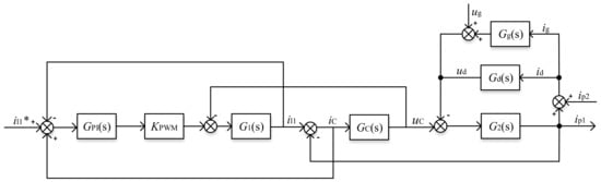
Figure 8.
RC resonance suppression circuit block diagram.
In Figure 8, Gd(s) is the equivalent impedance Laplace transform of the RC circuit, .
The frequency characteristic curve shown in Figure 9.
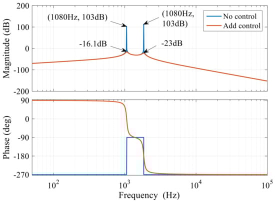
Figure 9.
RC resonance suppression circuit frequency characteristic curve.
As can be seen from Figure 9, before the control strategy is added, the resonance peak value of the inverter itself is 96.6 dB, and the resonance peak value of the grid-connected inverter cluster is 103 dB. By adding capacitor current feedforward and inverter-side current feedback control, the resonance peak value of the inverter itself drops to −23 dB. Adding the RC resonance suppression circuit, the resonance peak value of the cluster inverter grid-connected drops to −16.1 dB. It can be seen that the proposed control strategy can effectively suppress the resonance.
Considering that after the inverter cluster connected to the grid,the system power will change as the number of inverters increase or decrease, thus the resonance frequency will change as well. If taken RC-type global resonance suppression method,When the number of inverters and the power of the system are changed, the value of the RC will be recalculated, so it is difficult to practice. Therefore, the method is improved in this paper, according to the technology of thyristor switching capacitor [18], the thyristor switching RC circuit (TSRC) method is proposed. In this way, even if the power and number of the inverters are changed, the capacitors can be switched on and off automatically and the resonance generated by the grid-connected can be suppressed. The principle of TSRC is to use two anti-parallel thyristors equivalent to ideal switches, control capacitors into the grid or cut off from the grid. The capacitors are divided into several groups, so that the capacitor can be put into the grid hierarchically according to different resonance frequencies, and the resonance of the system will be suppressed. The TSRC schematic diagram is shown in Figure 10.
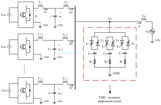
Figure 10.
TSRC resonance suppression schematic of grid-connected inverter cluster.
In the red dotted box of Figure 10, the thyristor switching capacitor groups are connected in parallel to the grid. There are three groups of switching units, which control the capacitor connected to the grid to suppress resonance through switching on and off the thyristor.
TSRC is a hierarchical switching method. The best grouping method is to use less capacitors to obtain more switching series in the case of the capacity is determined. There are two types of capacitor groupings: equal-capacity and unequal-capacity [19]. This paper takes the binary scheme of the unequal-capacity grouping [20], that is, the capacitor capacity is grouped by 1:2n−1. This method has more switching grades, the control effect is better, the maximum switching grade is 2n − 1, the capacitance grade differential is equal, as the minimum value of capacitance. In this paper, three groups of switching units are set up, and the switching grade is seven, the capacitor capacity is determined according to the 1:2:4 scheme. The minimum capacitance is 20 μF, so the three groups of capacitance values are 20 μF, 40 μF and 80 μF, respectively. The capacitor input grade and switching configuration are shown in Table 3.
Table 3.
Capacitor input grade and switching configuration.
In Table 3, 1 indicates that put into capacitor to the grid, 0 indicates that the capacitor switch off from the grid. This method can make the input capacitance range from 20 μF to 140 μF, the capacitance differential between each grade is 20 μF.
Total Harmonic Distortion (THD) can intuitively reflect the resonance degree of the system, so the THD control strategy is adopted to determine the number of switched capacitor grades, the THD control flow chart is shown in Figure 11. Start, the system performs THD detection, the resonance suppression of a single inverter is performed first after the resonance is detected. Then judged whether THD reaches the standard of grid-connected, if it does not, start the TSRC control strategy. The THD standard is set as 1%, the capacitor groups switch into the grid grade by grade, and be tested each time until THD ≤1%, it means that the resonance of the system has been suppressed. At this time, the capacitor switching is stopped.
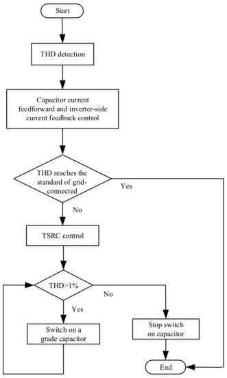
Figure 11.
THD control flow chart.
5. Simulation and Experimental Verification
5.1. Simulation Analysis
The simulation model of two photovoltaic cluster inverter grid-connected systems is built in MATLAB/Simulink. The simulation parameters are shown in Table 1; the control schematic diagram is shown in Figure 12. In Figure 12, the resonance suppression circuit of two inverters are the same, the switches K1, K2, and K3 input and disconnect the resonance suppression circuit from the photovoltaic cluster system.
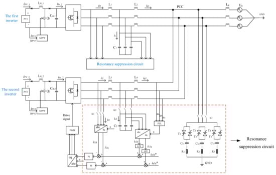
Figure 12.
Two sets of photovoltaic cluster inverter system control schematic diagram.
1. Disconnect K1, K2, K3
The system does not include the resonance suppression control strategy, the grid-connected current waveform and FFT harmonic analysis are shown in Figure 13.
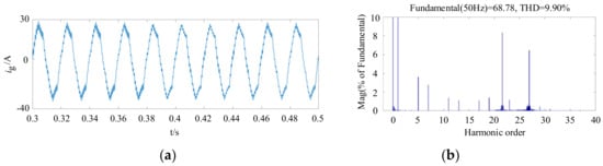
Figure 13.
(a) Grid-connected current waveform; (b) Grid-connected current harmonic analysis.
As can be seen from Figure 13, the current waveform is distorted and the grid-connected current generates resonance. The total harmonic distortion reaches 9.9%, of which the 22nd and 27th harmonic content are very high, which are inverter cluster grid-connected resonance and LCL inverter self resonance.
2. Close K1, K2, disconnect K3
The capacitor current feedforward and inverter-side current feedback control circuits are added. The PI regulator parameters kp = 5.7, ki = 50, the grid-connected current waveform and FFT harmonic analysis are shown in Figure 14.
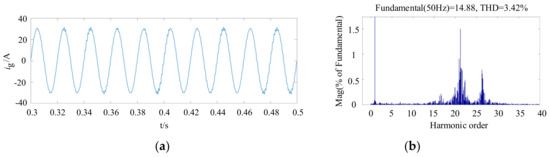
Figure 14.
(a) Grid-connected current waveform after capacitor current feedforward and inverter-side current feedback control; (b) Grid-connected current harmonic analysis.
From Figure 14 known, the total harmonic distortion of the grid-connected current is 3.42%, the 27th harmonic content of the inverter itself is 0.7%, and the resonance is suppressed; while the 22nd harmonic content is still high, indicating that the inverter cluster grid-connected resonance has not been effectively suppressed.
3. Close K1, K2, K3
The capacitor switching grade and THD waveform as shown in Figure 15. The TSRC resonance suppression circuit is added, the grid-connected current waveform and FFT harmonic analysis are shown in Figure 16.
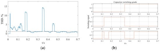
Figure 15.
(a) THD waveform; (b) Capacitor switching grade.
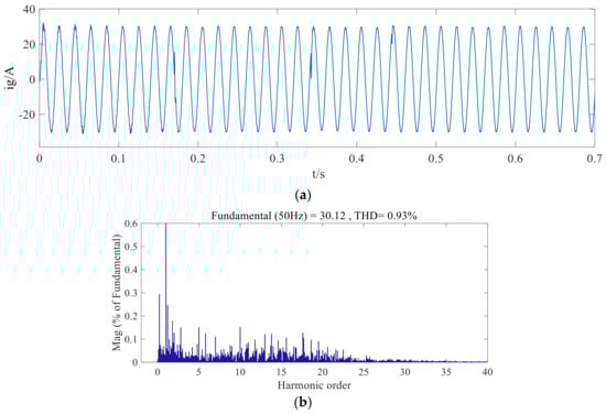
Figure 16.
(a) Grid-connected current waveform after TSRC resonance suppression; (b) Grid-connected current harmonic analysis.
As can be seen from Figure 15, the capacitor switching signal no longer changes after 0.45 s, the switching signal is 1, 0, 1 and five grades are input, indicating that the resonance has been suppressed at this time. The THD waveform is basically stable, only a small range fluctuation after 0.45 s. In Figure 16, the current distortion phenomenon decreases after 0.45 s, which indicates that the system is stable at 0.45 s. The total harmonic distortion of the grid-connected current is 0.93%, and the harmonic contents of the 22nd and 27th have been reduced to less than 0.2%, indicating that the system resonance has been suppressed effectively.
5.2. Experimental Verification
In this paper, two 380 V voltage level distributed photovoltaic system with capacity of 500 kW inverters are used as an experimental platform. The basic parameters of grid-connected inverter shown in Table 4.
Table 4.
Basic parameters of 500 kW inverter.
1. Single inverter resonance suppression test
The system does not include the resonance suppression control strategy; when the inverter is started, the grid voltage and current waveform are obviously distorted. The resonant frequency of the system is 1120 Hz through calculating, the measured value is in accordance with the calculated value, the measured line voltage and A-phase current waveforms are shown in Figure 17.
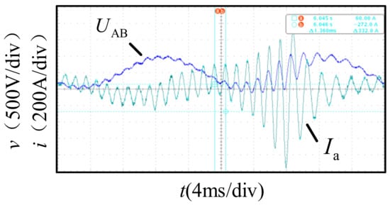
Figure 17.
Experimental waveform of single inverter before control.
After adding the control strategy, the inverter is started. The resonance is suppressed, the distortion of grid voltage waveform disappear and the oscillation of the current waveform is obviously reduced. The inverter works normally; the line voltage and A-phase current waveforms are shown in Figure 18.
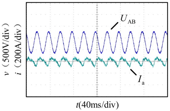
Figure 18.
Experimental waveform of single inverter after control.
2. Two inverters parallel resonance suppression test
The system does not include the resonance suppression control strategy; when the inverter is started, the grid voltage and current waveform are obviously distorted. The experimental data analyzed by FFT showed that there are two resonance points in the system, whose frequencies are 1003 Hz and 1120 Hz respectively. The measured line voltage and A-phase current waveforms are shown in Figure 19.
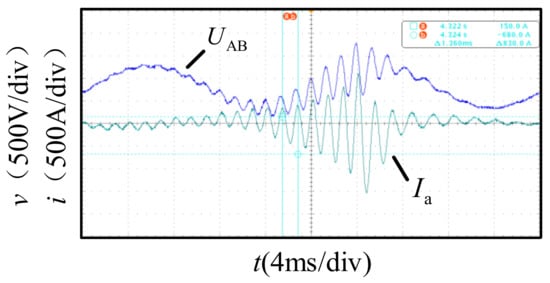
Figure 19.
Experimental waveform of two inverters before control.
After adding the control strategy, the inverter is started, the resonance points are all suppressed, the distortion of grid voltage waveform is disappeared and the oscillation of current waveform is obviously reduced. The inverters work normally, the line voltage and A-phase current waveforms are shown in Figure 20.
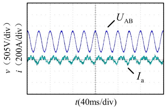
Figure 20.
Experimental waveform of two inverters after control.
6. Conclusions
Photovoltaic cluster inverter grid-connected can improve the efficiency of photovoltaic power plants, but it is difficult to effectively suppress the resonance generated by the inverter cluster grid-connected. In this paper, a control method of capacitor current feedforward and inverter-side current feedback is proposed to suppress the resonance generated by the LCL inverter. Based on this, RC-type global resonance suppression and TSRC circuit is added to restrain the resonance caused by photovoltaic cluster inverter grid-connected. Simulation and experimental results show that the control strategy can effectively suppress the resonance generated by the photovoltaic cluster system, and make the photovoltaic inverter cluster safely and steadily access the power grid to ensure the power supply reliability and grid power quality.
Acknowledgments
This work is supported by the Education Committee of Beijing basic research program of China (XN097) and Foundation of Collaborative Innovation Center of Key Power Energy-Saving Technologies in Beijing (PXM2016_014212_000016).
Author Contributions
Qingzhu Wan conceived of the main idea and provided the experimental platform. Hongfan Zhang proposed the control method and conducted the analysis, validated it in simulations and wrote the paper.
Conflicts of Interest
The authors declare no conflict of interest.
References
- Zhou, L.; Yang, M.; Liu, Q.; Guo, K. New control strategy for three-phase grid-connected LCL inverters without a phase-locked loop. J. Power Electron. 2013, 13, 487–493. [Google Scholar] [CrossRef]
- Lu, M.; Wang, X.; Loh, P.C.; Blaabjerg, F. Resonance interaction of multiparallel grid-connected inverters with LCL filter. IEEE Trans. Power Electron. 2016, 32, 894–899. [Google Scholar] [CrossRef]
- Sun, Z.; Yang, Z.; Wang, Y.; Xu, H. The cause analysis and suppression method of resonances in clustered grid-connected photovoltaic inverters. Proc. CSEE 2015, 35, 418–425. [Google Scholar]
- Chen, Y.; Guerrero, J.M.; Shuai, Z.; Chen, Z.; Zhou, L.; Luo, A. Fast Reactive Power Sharing, Circulating Current and Resonance Suppression for Parallel Inverters Using Resistive-Capacitive Output Impedance. IEEE Trans. Power Electron. 2016, 31, 5524–5537. [Google Scholar] [CrossRef]
- Teng, J.H.; Liao, S.H.; Huang, W.H.; Chiang, C.C. Smart Control Strategy for Conversion Efficiency Enhancement of Parallel Inverters at Light Loads. IEEE Trans. Ind. Electron. 2016, 63, 7586–7596. [Google Scholar] [CrossRef]
- Kumar, N.; Saha, T.K.; Dey, J. Modeling, control and analysis of cascaded inverter based grid-connected photovoltaic system. Int. J. Electr. Power Energy Syst. 2016, 78, 165–173. [Google Scholar] [CrossRef]
- Zhang, C.; Guerrero, J.M.; Vasquez, J.C.; Coelho, E.A.A. Control architecture for parallel-connected inverters in uninterruptible power systems. IEEE Trans. Power Electron. 2016, 31, 5176–5188. [Google Scholar]
- Beres, R.N.; Wang, X.; Blaabjerg, F.; Liserre, M.; Bak, C.L. Optimal design of high-order passive-damped filters for grid-connected applications. IEEE Trans. Power Electron. 2015, 31, 2083–2098. [Google Scholar] [CrossRef]
- Ye, J.; Shen, A.; Zhang, Z.; Xu, J.; Wu, F. Systematic design of the hybrid damping method for three-phase inverters with high-order filters. IEEE Trans. Power Electron. 2016, 33, 4944–4956. [Google Scholar] [CrossRef]
- Xu, J.; Xie, S.; Zhang, B. Stability analysis and improvement of the capacitor current active damping of the LCL filters in grid-connected applications. J. Power Electron. 2016, 16, 1565–1577. [Google Scholar] [CrossRef]
- Lorzadeh, I.; Abyaneh, H.A.; Savaghebi, M.; Bakhshai, A.; Guerrero, J.M. Capacitor current feedback-based active resonance damping strategies for digitally-controlled inductive-capacitive-inductive-filtered grid-connected inverters. Energies 2016, 9, 642. [Google Scholar] [CrossRef]
- Guzman, R.; Vicuña, L.G.D.; Morales, J. Model-Based Active Damping Control for Three-Phase Voltage Source Inverters with LCL Filter. IEEE Trans. Power Electron. 2017, 32, 5637–5650. [Google Scholar] [CrossRef]
- Wang, X.; Bao, C.; Ruan, X.; Li, W.; Pan, D. Design considerations of digitally controlled LCL-filtered inverter with capacitor- current-feedback active damping. IEEE J. Emerg. Sel. Top. Power Electron. 2017, 2, 972–984. [Google Scholar] [CrossRef]
- Hu, W.; Zhou, Y.; Du, Z.; Zhang, K.; Wang, T.; Sun, J.J. Research on resonance suppression strategy of system with multiple grid-connected inverters. Power Syst. Prot. Control 2017, 45, 45–50. [Google Scholar]
- Hu, W.; Zhou, H.; Sun, J.J.; Jiang, Y.M.; Zha, X.M. Resonance analysis and suppression of system with multiple grid-connected inverters. In Proceedings of the 2015 International Future Energy Electronics Conference (IFEEC), Taipei, Taiwan, 1–4 November 2015. [Google Scholar]
- Sun, J.J.; Hu, W.; Zhou, H.; Jiang, Y.M.; Zha, X.M. A Resonant Characteristics Analysis and Suppression Strategy for Multiple Parallel Grid-connected Inverters with LCL Filter. J. Power Electron. 2016, 16, 1483–1493. [Google Scholar] [CrossRef]
- Li, Z.; Xia, K.; Jiang, Q.; Wang, Y.; Xu, P. Analysis and simulation on active damping control of resonance in multi-parallel grid-connected inverters system. In Proceedings of the 2017 20th International Conference on Electrical Machines and Systems (ICEMS), Sydney, Australia, 11–14 August 2017. [Google Scholar]
- Shen, B.; Yin, B.; Sun, W.; Xue, P. Research of thyristor switching capacitor based on reactive power compensation controller. Electr. Meas. Instrum. 2015, 52, 87–90. [Google Scholar]
- Sheng, Z.; Zeng, F.; He, T. Switching Strategy for Two Control Three Type of Thyristor Switched Capacitor. Mod. Sci. Instrum. 2013, 4, 138–141. [Google Scholar]
- Li, X.; Li, Z.; Jiang, Y.L. Analysis and simulation research of switching process for thyristor controlled three-phase capacitor. Electric Driv. Autom. 2014, 36, 11–14. [Google Scholar]
© 2018 by the authors. Licensee MDPI, Basel, Switzerland. This article is an open access article distributed under the terms and conditions of the Creative Commons Attribution (CC BY) license (http://creativecommons.org/licenses/by/4.0/).