Article

A Distributed Secondary Control Algorithm for Automatic Generation Control Considering EDP and Automatic Voltage Control in an AC Microgrid

1
School of Information Science and Engineering, Yuelu Road, Central South University, Changsha 410083, China
2
School of Automation Science and Electrical Engineering, Xueyuan Road, Beihang University, Beijing 100191, China
3
ShenZhen Polytechnic, Shenzhen 518055, China
4
Huangshi Electric Power Supply Company in State Grid, Huangshi 435000, Hubei, China
*
Authors to whom correspondence should be addressed.
Energies 2018, 11(4), 932; https://doi.org/10.3390/en11040932
Submission received: 8 March 2018 / Revised: 4 April 2018 / Accepted: 12 April 2018 / Published: 13 April 2018
(This article belongs to the Collection Smart Grid)

Abstract

:
This paper introduces a distributed secondary control algorithm for automatic generation control (AGC) and automatic voltage control (AVC), which aims at matching area generation to area load and minimizing the total generation cost in an alternating current (AC) microgrids. Firstly, the control algorithm utilizes a continuous-time distributed algorithm to generate additional control variables to achieve frequency-voltage recovery for all distributed generators (DGs). Secondary, it solves the economic dispatch problem (EDP) by a distributed economic incremental algorithm in the secondary control level, which avoids the problem caused by communication speed inconsistency between secondary and tertiary control levels. This study also utilizes a fully distributed strategy based on secondary communication network to estimate the total load demand. In addition, the proposed algorithm can be used to realize a seamless handover from the islanded mode to the grid-connected mode, run under the condition of short time communication system out of action, and help to realize the plug and play function. Lastly, the stability of the proposed control algorithm is analyzed and proved, and the effectiveness of the method is verified in some case studies.

1. Introduction

A microgrid is a small power generation and distribution system, which consists of photovoltaic (PV) [1], wind power [2,3], and other green renewable resources such as fuel cells and hydroelectric generations. The microgrid is designed to be an autonomous system that achieves control, protection, and management. It can be worked in three control modes: grid-connected mode, islanded mode, and synchronized mode [4,5]. When the microgrid is connected to the main-grid, it can be regarded as a component unit of the active distribution network, and it can be managed and controlled according to the idea of virtual power plant (VPP) [6]. While the microgrid is operating in the islanded mode, its primary control target is to maintain voltage-frequency stability and guarantee the power balance for the whole system.
At present, among the control strategies of microgrids, the hierarchical control is the mainstream control scheme [7,8,9,10], which is inspired by the control framework of the traditional power grid. It is divided into three control layers, namely, primary control, secondary control, and tertiary control. Each control layer has its own control goals and running time scale.
The primary control generates frequency-voltage reference values for inner voltage and current control loop, which commonly employs P-f/Q-v control strategy by mimicking the governor of a synchronous generator in the [11,12]. The droop control has the shortest running time scale, usually in milliseconds to seconds, and is a fully decentralized control form without any communication. By reasonably setting the droop coefficients, the load demand can be equally divided or distributed according to a certain proportion. However, the deviation value of frequency-voltage between the output reference and their rated values will increase because of the larger droop coefficients. To eliminate the deviation caused by primary control, a restoration control called secondary control is introduced. It is responsible for maintaining the system frequency and output voltage amplitude at their rated values, synchronizing the output of DG cluster. The secondary control runs in a short running time scale, usually 2–4 s [7]. The tertiary control is used to manage power flow and achieve economic dispatch for microgrids, in which the sampling time to solve the economic dispatch problem (EDP) is every few minutes, usually 1–5 min or hourly [1,7,13]. The running time scale is longer than that of the secondary control layer.
This paper mainly focuses on the secondary control and the tertiary control. Up to now, scholars have respectively put forward many constructive views and methods on these two control levels. Scholars in [14] propose using a centralized proportional-integral (PI) controller to obtain voltage-frequency deviations, and then sending the deviations to the all global DGs in the centralized communication network. However, it has been gradually replaced by a distributed control mode because of its costly communication infrastructure, poor augmentability, and susceptibility to communication delay and failure. Scholars in [15] designed a novel approach secondary control method to solve voltage-frequency deviation problem by a distributed mode. Though it solves voltage-frequency restoration, this method is complex in calculation, large in communication data, and is not easier to realize than the centralized mode [16,17]. A cooperative sliding-mode control method in [18] is introduced, to solve frequency and voltage restoration, in which the frequency-voltage restoration is seen as a distributed tracking problem, and the stability of algorithm is proven by using a Lyapunov function.
For the tertiary control level, most researchers concentrate on solving the EDP. At first, a centralized control method in [19] is presented for the optimization of the microgrid operation. Then some scholars offer using decentralized approaches [20,21,22] to replace the centralized control, because the decentralized approaches only depended on local DG information, did not need communication. However, these decentralized modes realized by the droop control can hardly avoid the inherent disadvantages as mentioned above. Now, more and more scholars pay attention to the distributed control mode to overcome the drawbacks of the centralized control and the decentralized mode. In [23], an incremental cost distributed algorithm is presented for smart grid, which not only analyzes the convergence speed under two kinds of communication network topologies, but also considers the generator capacity. In [24], the authors present a novel distributed optimal dispatch algorithm for multiple generations that computes active power references for local controller in a distributed manner and strictly proves the stability of the proposed algorithm. The author of [25] proposes a distributed consensus algorithm for EDP with a changing communication graph, which guarantees the balance between supply and demand for the smart grid system timely.
However, the above-mentioned voltage-frequency recovery problem and EDP are always dealt with separately, which leads to suboptimal operation of microgrids because of the inconsistency of running time scale of the tertiary control and the secondary control [8,13]. Recently, some scholars begin to note how to integrate traditional automatic generation control/automatic voltage control (AGC/AVC) technology and EDP in the secondary control level. In [13], a connecting AGC and ED algorithm is proposed to improve the economic efficiency of AGC under the condition of load changing. Li in [8] designed a distributed hierarchical control for parallel inverters operated in an islanded AC microgrid, in which economic AGC and AVC were implemented in the secondary control level. However, these methods in the above papers just consider AGC and EDP for the traditional power grid, or are only suited for running in the islanded mode, which is worth ongoing study.
Inspired by the above ideas, a two-level algorithm for an AC microgrid with five DGs is proposed in this paper, which combines the voltage-frequency regulation for traditional AGC/AVC and EDP in the secondary control level. The proposed algorithm was helpful to work out the suboptimal economical operation of microgrids caused by the time scale inconsistency between the secondary level and the tertiary level. In addition, a distributed local demand estimator is designed to estimate the total power demand replacing the traditional Microgrid Central Controller (MGCC). Furthermore, the proposed secondary voltage-frequency recovery algorithm can be operated in three operation modes, namely, islanded mode, grid-connected mode, and synchronized mode, and thus it is in line with the flexible, reliable, and plug-and-play characteristics of microgrids. Furthermore, the proposed secondary control is fully distributed using a ring communication topology, which enhances the system stability, especially when there is a failure in the communication network of the system.
This paper is organized as follows: Section 2 presents a basic AGC/AVC workflow and its control objectives. Section 3 introduces a distributed secondary control algorithm based on the distributed communication network for AGC/AVC, which contains a voltage-frequency recovery algorithm, an economic incremental algorithm for economic operation of a microgrid and a local load demand estimator, and then proves the stability of the proposed control algorithm. Some simulations under different conditions are presented in Section 4. Finally, the conclusion and future work are drawn in Section 5.

2. Control Structure and Control Objects for Microgrids

The AGC and AVC are commonly used in the traditional grid scheduling, and they are also used to manage and synchronize all kinds of DGs to satisfy the power demand of the microgrids [1].
Usually, the AGC/AVC is applied to manage the microgrid in the secondary control level. The AGC/AVC workflow is displayed in Figure 1, and the microgrid is planned to attain the following objectives [1,26]:
  • Voltage synchronization:
    V i V j : V P C C V M a i n G r i d , i j
    where Vi and Vj are the real output voltages of the i-th and j-th DGs, correspondingly, and VPCC and VMainGrid are the voltages of the point of common coupling (PCC) and the main grid, respectively.
  • Frequency synchronization:
    f i f j : θ P C C θ M a i n G r i d , i j
    where fi and fj are the frequencies of the i-th and j-th DGs, correspondingly, and θPCC and θMaingrid are the phase angles [rad] of the PCC and the main grid, respectively.
  • EDP: To minimize the total active generation costs of microgrids:
    min C t o t a l = min i = 1 n C i ( P G i )
    where Ci(PGi) is a comprehensive cost function of the active generation [13,24,25,27], which can be written as:
    C i ( P G i ) = α i P G i 2 + β i P G i + γ i , i = 1 , 2 , , n
The cost coefficients αi, βi, and γi are positive real numbers. The Ci(PGi) may include generation cost, maintenance cost and so on. Moreover, Equation (4) does not contain reactive power, which is because the reactive power cost is less than 1% of the active power cost [8].

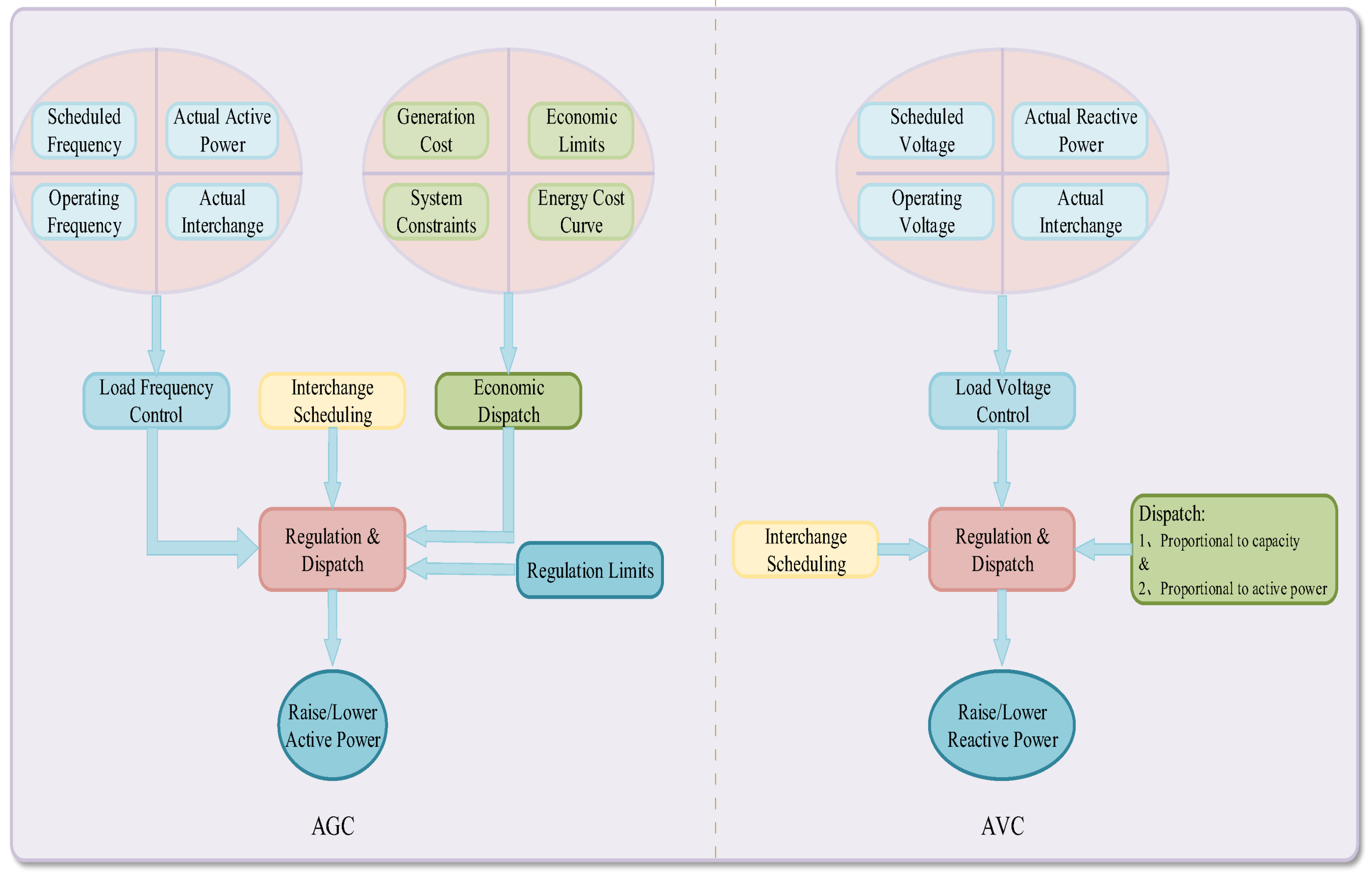
3. Design of a Distributed Secondary Control Algorithm for the AGC/AVC and EDP Problems

Usually, the first two goals discussed in the previous section are realized in the secondary control level by the central control mode, while the final object for EDP is solved in the tertiary control level, which decreases economic efficiency of the microgrids. Meanwhile, the central control pattern needs to gather the global key point information, which is a great challenge regarding communication construction and investment, especially when the number of DGs is large and their geographical locations are scattered [7]. Therefore, a secondary distributed control algorithm is proposed in this section, which combines traditional secondary control and distributed control strategy with a small amount of communication. Next, we introduced this control algorithm and analyze its stability.

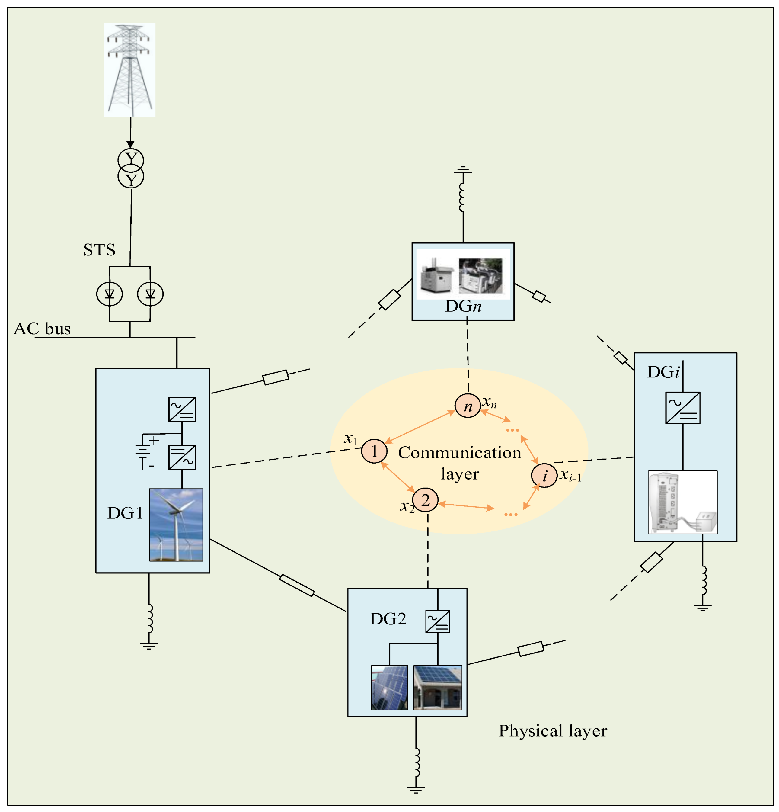
3.1. Microgrid Structure Wirh Communication Network

In this paper, a two-layer control system for AGC/AVC [1,28] in an AC microgrid was built as in Figure 2. In the first layer, the AGC/AVC obtains real-time measurement data through a communication network, displaying these data in the Supervisory Control and Data Acquisition (SCADA) system, while in the next layer is a real physical layer that consists of DGs, loads and local controllers (LCs).
In Figure 2, xi is a state value for the i-th DG, which represents voltage, frequency, active power, reactive power, incremental cost, etc. These state values are transmitted through the communication network. If there is a communication link from the i-th DG to the j-th DG, then aij = 1, otherwise aij = 0. In addition, if the i-th DG is reachable from every other DG, it is said to be globally reachable [25]. If each DG is globally reachable, the communication network is said to be strongly connected. The basic requirement of distributed algorithm to run favoringly is that the communication topology should keep in a strongly connected graph. A distributed algorithm [23,29] is given as:
{ x ˙ i = u i u i = j = 1 , j i n a i j ( x i x j ) , i = 1 , , n
which also can be written in the matrix form as:
x ˙ = L x
where x = [x1, x2, …, xn]T, and Laplacian matrix L is defined as:
L { l i i = i j a i j ,   for   on-diagonal   elements l i j = a i j ,   for   off-diagonal   elements
If and only if xi = xj for all i, j [30,31], it says that all DGs have reached a synchronization.

3.2. Distributed Voltage-Frequency Recovery and Synchronization for AGC/AVC

Due to the characteristics of the droop controller, the output voltage and frequency is lower than the references. To solve this problem, a voltage-frequency recovery algorithm is presented to eliminate the voltage and frequency errors between output voltage and reference voltage, or the voltage of the main grid. For the i-th inverter, the reference values of the output frequency and voltage, f i r e f and v d i r e f , are varied according the following formula:
{ f i r e f = f * m i P G i + Δ f i = f * e P G i + Δ f i v d i r e f = E * n i Q G i + Δ v i = E * e Q G i + Δ v i
where f* and E* indicate the rated values, mi and ni are the P-f and Q-V droop coefficients of the i-th DG, respectively. Because the voltage-frequency recovery and synchronization problems are the first two problems to be solved, thus mi and ni are seen as constant values, while EDP is described in detail in the next section. In addition, Δfi and Δvi are the additional control variables that are used to restore the output frequency-voltage to the nominal values with the changing load.
To cover the shortages of the central control mode, this study employs a continuous-time coordination control algorithm to restore the voltage-frequency deviation. Firstly, the Equation (8) is differentiated to get the following expression:
{ f ˙ i r e f = m i P ˙ G i + Δ f ˙ i = u f i v ˙ d i r e f = n i Q ˙ G i + Δ v ˙ i = u v i
Let:
{ m i P ˙ G i = u f 1 i , Δ f ˙ i = u f 2 i n i Q ˙ G i = u v 1 i , Δ v ˙ i = u v 2 i
where uf1i, uf2i, uv1i, and uv2i are two auxiliary control inputs for frequency and voltage restore, respectively. They are obtained by exchanging measured information with their neighboring DGs. Base on the two-layer control system for AGC in Section 3.1, distributed auxiliary control inputs for frequency-voltage regulation is proposed, and the specific expressions are as follows:
{ u f 1 i = k f 1 ( j = 1 , j i n a i j s i g n ( m i P G i m j P G j ) | m i P G i m j P G j | k 2 ) u v 1 i = k v 1 ( j = 1 , j i n a i j s i g n ( n i Q G i n j Q G j ) | n i Q G i n j Q G j | k 2 )
and:
{ u f 2 i = k f 2 ( j = 1 , j i n a i j s i g n ( Δ f i Δ f j ) | Δ f i Δ f j | k 2 + b i s i g n ( Δ f i Δ f e ) | Δ f i Δ f e | k 2 ) u v 2 i = k v 2 ( j = 1 , j i n a i j s i g n ( Δ v i Δ v j ) | Δ v i Δ v j | k 2 + b i s i g n ( Δ v i Δ v e ) | Δ v i Δ v e | k 2 )
where kf1, kv1, kf2, and kv2 are the positive gains for the i-th integrator, and k2 is a positive control gain (0 < k2 < 1). In addition, if the i-th DG is a leader, then bi = 1; otherwise, bi = 0. Only the leader DG receives the voltage-frequency error signal from the upper controller. In practice, the greater the number of leader DGs of the microgrid, the higher the speed of communication speed, and the corresponding construction cost would be increased, which is a process of weighing the pros and cons between the time of synchronization and the communication investment. Furthermore, Δfe and Δve in the Equation (12) are the deviation signals, which are only generated by a PI controller according to the feedback error signal in the leader DGs. The detailed expression is as follows:
{ Δ f e = k p f s ( f * f i r e f ) + k i f s ( f * f i r e f ) d t Δ v e = k p v s ( E * v d i r e f ) + k i v s ( E * v d i r e f ) d t
where kpfs and kpvs are the proportional coefficients, and kifs and kivs are the integral coefficients. Next, the stability of the proposed distributed algorithm is proved as follows.
Theorem 1.
For an AC microgrid with multi-parallel DGs, supposed that the communication topology is undirected and sparse communication between DGs, then all the frequency fi and voltage vdi of DGs will tend to be converged to the reference value f* and E* under the action of control input ufi and uvi.
Proof of Theorem 1.
Because the voltage-frequency restore and synchronization control method are the same, to simplify the analysis, only stability analysis for the proposed algorithm to solve the frequency recovery is shown here. For the control input ufi of the i-th DG, the following Lyapunov function is considered:
V ( f ) = 1 2 i = 1 n ( m i P G i ) 2 + 1 2 i = 1 n ( Δ f i ) 2
It can be seen from the Equation (14), this Lyapunov function V ( f ) is a continuously differentiable function, and V ( f ) 0 is apparently established. Then:
V ˙ ( f ) = 1 2 i = 1 n ( m i P G i ) 2 + 1 2 i = 1 n ( Δ f i ) 2 = i = 1 n m i P G i ( m i P ˙ G i ) + i = 1 n Δ f i Δ f ˙ i
substituting the Equations (11) and (12) into the Equation (15), the following Equation (16) can be obtained.
V ˙ ( f ) = i = 1 n m i P G i ( m i P ˙ G i ) + i = 1 n Δ f i Δ f ˙ i = k p i = 1 n 1 j = i + 1 n a i j ( m i P G i m j P G j ) s i g n ( m i P G i m j P G j ) | m i P G i m j P G j | k 2 k f i = 1 n 1 j = i + 1 n a i j ( Δ f i Δ f j ) s i g n ( Δ f i Δ f j ) | Δ f i Δ f j | k 2 k f i = 1 n b i ( Δ f i Δ f e ) s i g n ( Δ f i Δ f e ) | Δ f i Δ f e | k 2 0
Hence, the proposed control algorithm is asymptotically stable. Let V ˙ ( f ) = 0 , only when the following two equations can be satisfied:
m 1 P G 1 = m 2 P G 2 = m i P G i = = m n P G n
Δ f 1 = Δ f 2 = Δ f i = Δ f n = Δ f e
where V ˙ ( λ ) = 0 is set. It is an equilibrium point of system, and the frequency of all DGs will converge to the reference value f*. □
The stability analysis of voltage recovery for the multi-parallel DGs is similar to the above method, so it will not be repeated here.
Remark 1.
The above Equation (13) is only available for the islanded mode. As for the grid-connected and synchronizing modes, the rating value f* and E* can be replaced by the frequency and voltage of the main grid. Moreover, this control algorithm can not only achieve frequency-voltage recovery and synchronization, but also is robust for distributed systems, because once the system has severe communication faults, the system becomes completely decentralized mode and can still keep stable for a period. This advantage has very important practical significance.

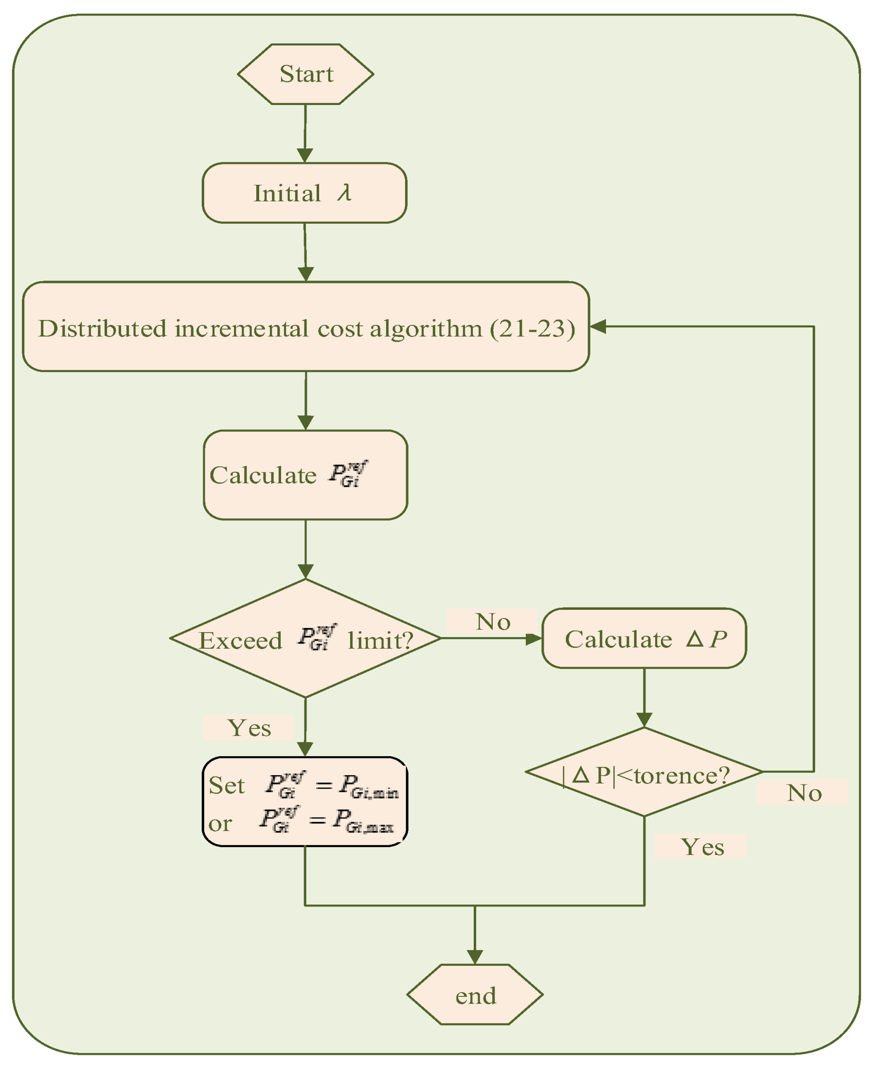
3.3. Distributed Algorithm to Solve EDP for AGC

According the third control object of AGC, some methods are designed to allot the changing loads among DGs to minimize the operating cost, i.e., EDP. In other words, we needed to design the reasonable droop coefficient to make the active power of DGs equal to the reference active power and to ensure economic optimization.

3.3.1. Without Consideration of Capacity Constraints

Firstly, according to the first-order optimal condition of the Lagrange function, the optimal incremental cost can be solved by a traditional centralized mode [24,25], which shows as follows:
λ * = ( P D + i = 1 n β i 2 α i ) / i = 1 n 1 2 α i
where λ* is the optimal incremental cost value, PD is the total demanded active power, which can be obtained using the power flow calculation. When the incremental values of all DGs are equal to the optimal value, the operation cost is minimal. Hence, the optimal active power generation reference for each DG is:
P G i * = λ * β i 2 α i
Unlike above centralized mode, in this section, a continuous-time distributed economic incremental algorithm is introduced to search the optimal solutions for λ* and P G i * . Above all, without considering the capacity constraint condition. The derivative of λi is obtained by the following expression:
λ ˙ i = k λ u λ i
Similarly, let distributed auxiliary control input u λ i :
u λ i = ( j = 1 , j i n a i j s i g n ( λ i λ j ) | λ i λ j | k 2 + b i Δ P )
where:
Δ P = k p p s ( P D i = 1 n P G i ) s i g n ( P D i = 1 n P G i ) | P D i = 1 n P G i | k 2
and kpps is a positive proportional coefficient. In the past, the load demand PD can be computed in a centralized mode, which is no longer applicable to the current distributed and scatter microgrids. Here, the load demand PD can be estimated in a distributed mode, which will be described in detail in Section 3.3.3. When the total load demand is known, ΔP can be calculated by (23), and then the ΔP is delivered to the leader DGs and transmitted to the follower DGs by a distributed communication network.
Theorem 2.
For an AC microgrid with multi-parallel DGs, supposed that the communication topology is undirected and sparse communication between DGs, then the incremental cost λi and the active power PGi will tend to be the optimal value λ* and P G i * under the action of the control input uλi, thereby the whole microgrid system attains the economic optimization.
Proof of Theorem 2.
For the input uλi of the i-th DG, the following Lyapunov function is considered:
V ( λ ) = 1 2 i = 1 n ( λ i ) 2
Apparently, V ( λ ) 0 is constantly satisfied. Then:
V ˙ ( λ ) = i = 1 n λ i λ ˙ i = i = 1 n λ i k λ u λ i
substituting the Equations (22) and (23) into the Equation (25), the Equation (26) can be obtained:
V ˙ ( λ ) = i = 1 n λ i λ ˙ i = k λ i = 1 n λ i ( j = 1 , j i n a i j s i g n ( λ i λ j ) | λ i λ j | k 2 + b i Δ P ) = k λ i = 1 n 1 j = i + 1 n a i j ( λ i λ j ) s i g n ( λ i λ j ) | λ i λ j | k 2 k λ k p p s i = 1 n i = 1 n b i λ i ( P D i = 1 n P G i ) s i g n ( P D i = 1 n P G i ) | P D i = 1 n P G i | k 2 0
Therefore, the proposed control algorithm is asymptotically stable. Let V ˙ ( λ ) = 0 , thus only when the following two equations can be satisfied:
λ 1 = λ 2 = λ i = = λ n
P D = i = 1 n P G i = i = 1 n λ i β i 2 α i
V ˙ ( λ ) = 0 is set. It is an equilibrium point of the system, thus the optimal incremental cost, Equation (19), and the optimal reference value of active generation, Equation (20), in the condition of non-capacity constrains are obtained according to the Equations (27) and (28). □

3.3.2. Capacity Constraints Considered

There is no doubt that the power of DGs cannot be infinitely large, which is always affected by the volume, sunlight and so on; thus the maximum power of DG is always changing in real time. For this reason, we must consider the actual situation. The distributed algorithm is also used to solve the problem, but the process is slightly different, which can be seen in Figure 3.
According to Figure 3, in the process of solving the optimal incremental cost, we need to judge the active power reference P G i r e f . If P G i r e f is out of range, the P G i r e f is set to the maximum or minimum, and the incremental cost λi of the i-th DG is not involved in the iterative computation, while the remaining DGs continue to participate in the computation until ΔP is within the tolerant range. Here, the generation constraint is considered, the optimal incremental cost is changed to be:
λ * = P D i = 1 , i n s a t n P G i + i = 1 , i n s a t n β i 2 α i i = 1 , i n s a t n 1 2 α i
and the optimal reference values of output active generation for all DGs are changed to be:
{ P G i * = λ * β i 2 α i , i n , i n s a t P G i * = P G i , min   or   P G i , max , i n s a t
where nsat is a set of saturation generators.

3.3.3. Load Demand Estimator

Load demand is always changing in real situations. Because the distributed secondary control method proposed in this paper cancels the tertiary control and the MGCC, the load demand becomes difficult to calculate, and these loads are scattered on the microgrid. Inspired by the average voltage estimator [32,33], a load demand estimator based on distributed average consensus algorithm is presented in this paper. The details are as follows:
P ^ D i ( t ) = n P G i ( t ) 0 t i , j = 1 , i j n a i j ( P ^ D i ( t ) P ^ D j ( t ) ) d t
where P ^ D i ( t ) is the local demand estimated value for i-th DG, which only updates its own estimate value with the help of communication network of the secondary control level. PGi(t) is the real output active generation for i-th DG at t time. In this way, all demand estimated values would converge to a same value in steady state:
P ^ D i = P ^ D 2 = = P ^ D n = i = 1 n P G i = P D
where the same value in steady state is the actual load demand.

3.3.4. Droop Coefficients Design
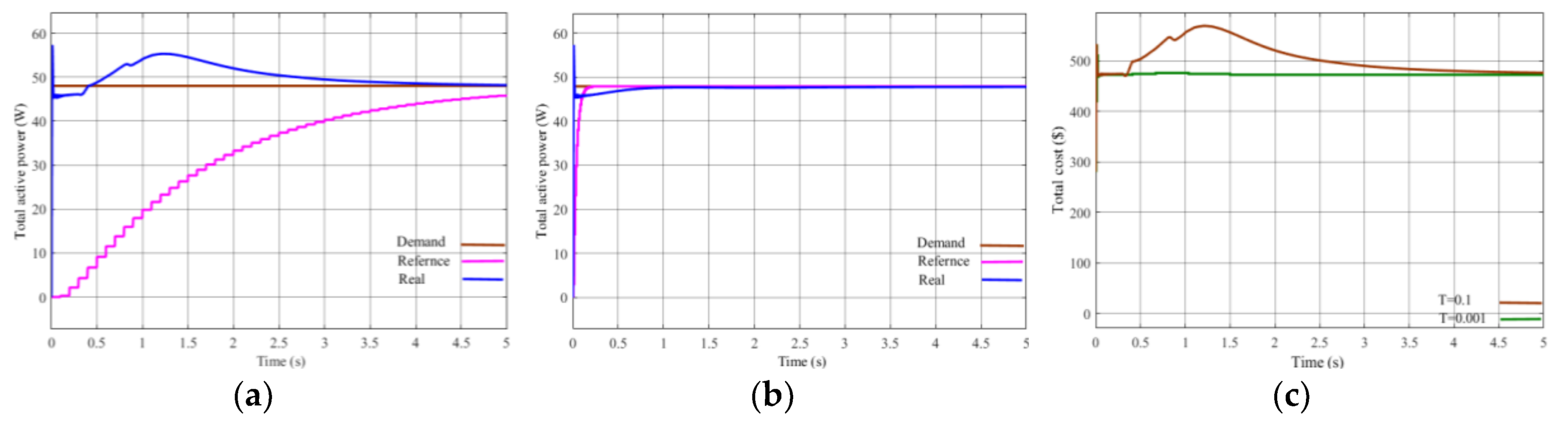
Based on the above analysis, the optimal incremental cost λ i * , the optimal reference active power generation P G i * and the load demand PD are solved by the distributed algorithm. Then, the droop coefficient can be designed according the process reference value of active power P G i r e f , and the droop coefficient must meet the following conditions:
m i = ρ P i / P G i r e f
ρ P 1 P G 1 P G i r e f = ρ P 2 P G 2 P G 2 r e f = ρ P n P G n P G n r e f = η p
where P G i r e f is a transient process reference value of the active power in the iterative calculation process, which will converge to the optimal reference active power generation P G i * under the above distributed algorithm. ηi and ρi are proportional coefficients, and they should satisfy the following expression:
η p 1 ρ P 1 = η p 2 ρ P 2 = η p n ρ P n = 1
In this way, the system will achieve the balance between supply and demand in finite time.
Remark 2.
The proposed distributed algorithm is applicable to the strong connected communication topology by estimating the mismatch between the load demand and the actual output generated power. Unlike the existing distributed control methods for the EDP, the method in this paper can be applied to the undirected graph, which does not need a two-way communication to ensure power balance.
In the past, the EDP has usually been solved in the upper controller as SCADA, in which the communication speed is lower than the secondary controller, leading to power mismatching of demand and supply. Figure 4 shows the condition at different communication speed.
From the above figures, we can see that the slower the communication speed is, the longer the power mismatch will be, and the poorer the economy performs. Therefore, the EDP is settled in the secondary control level in this paper, which can increase the communication speed without increasing the investment cost.

4. Simulation

In this paper, a tested AC microgrid with five identical DGs and some linear loads was simulated in Matlab/Simulink, which is designed to testify the effectiveness of the proposed distributed secondary control approach. The topology of the communication network with five nodes employs ring structure as Figure 2, that is, all DGs only communicate with its adjacent nodes and the associated Laplace matrix L is:
L = [ 2 1 0 0 1 1 2 1 0 0 0 1 2 1 0 0 0 1 2 1 1 0 0 1 2 ]
Unless otherwise stated, node 1 is the only master DG, which can receive voltage-frequency deviation signals and synchronization instruction from the upper controller. It can be verified that the communication graph is strongly connected. For a three-phase islanded AC microgrid, the generator parameters are as follows:
DG1–DG5: Lf = 3 mH, Cf = 150 μF, Rs = 0.1 Ω, Lline = 3 mH, Rline = 1 Ω, nominal frequency f* = 50 Hz, nominal voltage E* = 311 V.
The key control parameters and operation cost coefficients for each DG are given in Table 1 and Table 2, respectively.

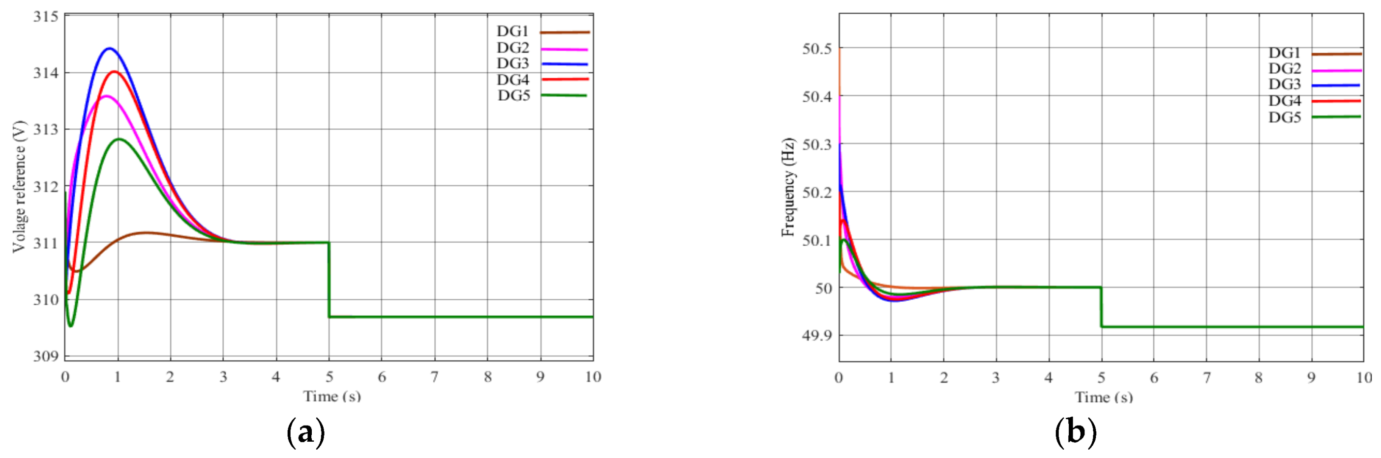
4.1. Case 1: Simulation Results of Voltage and Frequency Recovery and Synchronization

Figure 5a,b show the simulation results of voltage-frequency recovery and synchronization. When t ≤ 5 s, the proposed voltage-frequency recovery algorithm is utilized, all voltages and frequencies of DGs are converged to the set point 311 V and 50 Hz, while voltage-frequency dropped below set points when t > 5 s without voltage-frequency recovery algorithm.

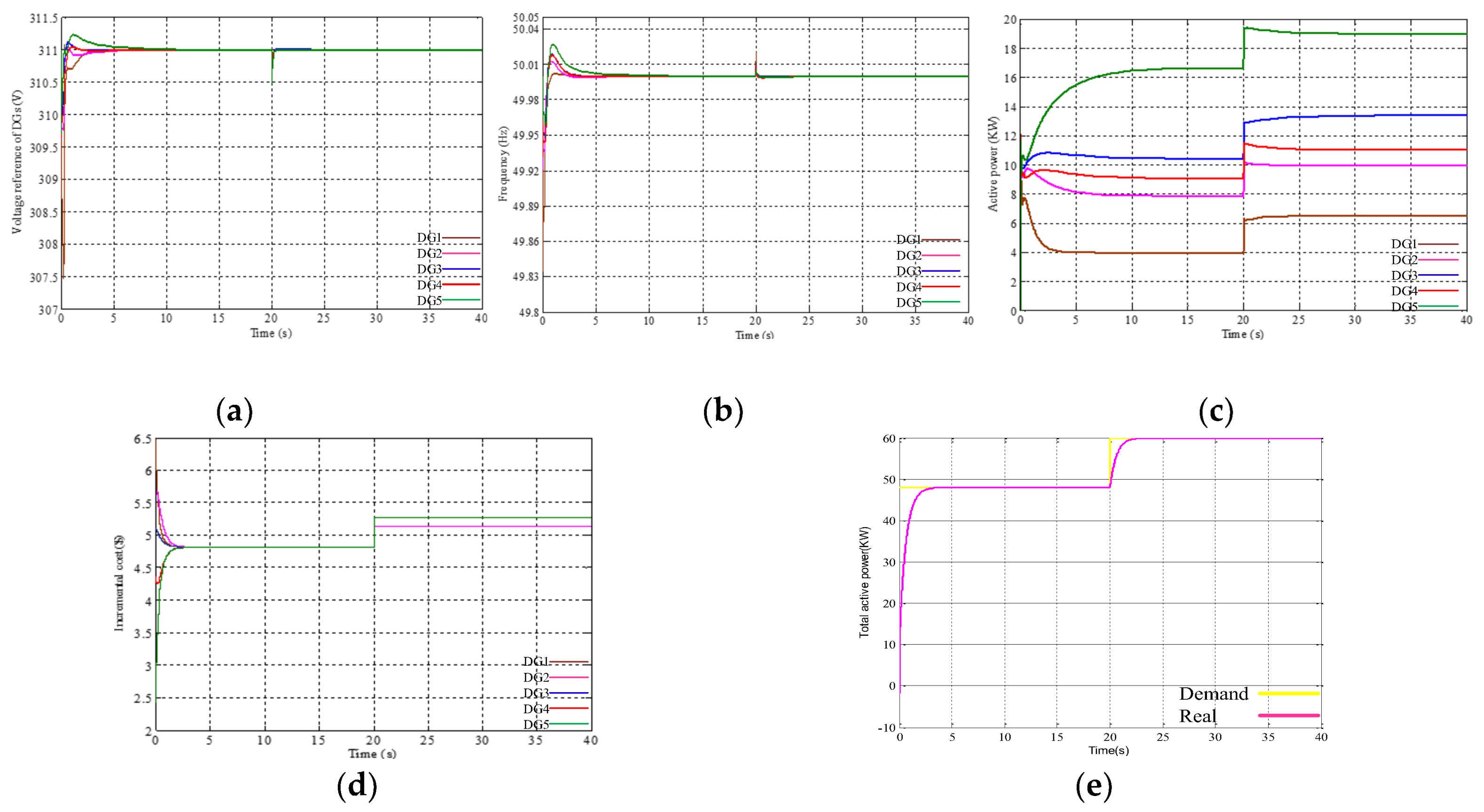
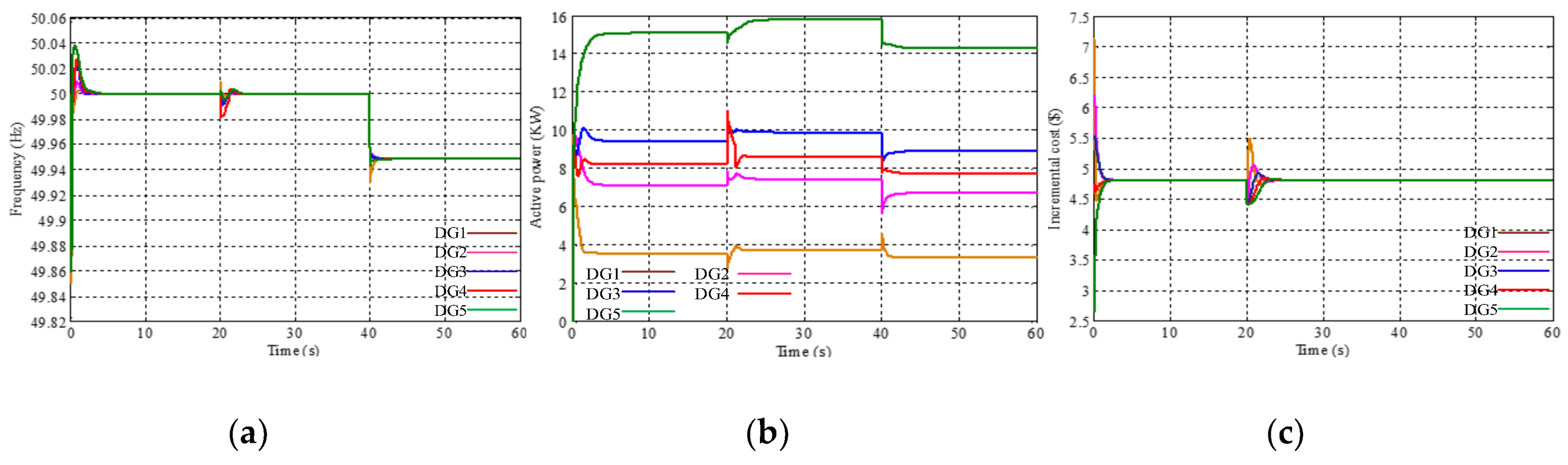
4.2. Case 2: Simulation Results with Load Changing

There are two stages in this simulation. When t ≤ 20 s, the total demand Pd = 48 KW; when t > 20 s, the total demand changes to Pd = 60 KW.
Stage 1: In this case, the active power output of each DG is within the limit of its power maximum value when t ≤ 20 s. Based on the Equations (19) and (20), the optimal incremental cost is obtained: λ* = 4.814 ($/KW), and the corresponding output active power reference values for the generators are: P G 1 * = 3.93 KW, P G 2 * = 7.86 KW, P G 3 * = 10.43 KW, P G 4 * = 9.08 KW and P G 5 * = 16.70 KW.
Stage 2: When t > 20 s, DG2 reaches its maximum value of 10 KW, and there is no increase in its active power output. At the same time, a new equilibrium is achieved for the remaining four DGs. According to Equations (29) and (30), the optimal incremental cost is λ* = 5.2625 ($/KW) at this stage and the corresponding output active power reference values for the generators are: P G 1 * = 6.51 KW, P G 2 * = 10.00 KW, P G 3 * = 13.42 KW, P G 4 * = 11.08 KW and P G 5 * = 19.00 KW.
Figure 6a–e show the simulated outputs obtained with the proposed control strategy by considering the generator constraint, which clearly indicate that the proposed method can make the voltage-frequency synchronization, incremental cost tend to the optimal value λ* according to the Theorem 2, and make the output active power of all DGs satisfy the balance of supply and demand within finite time.

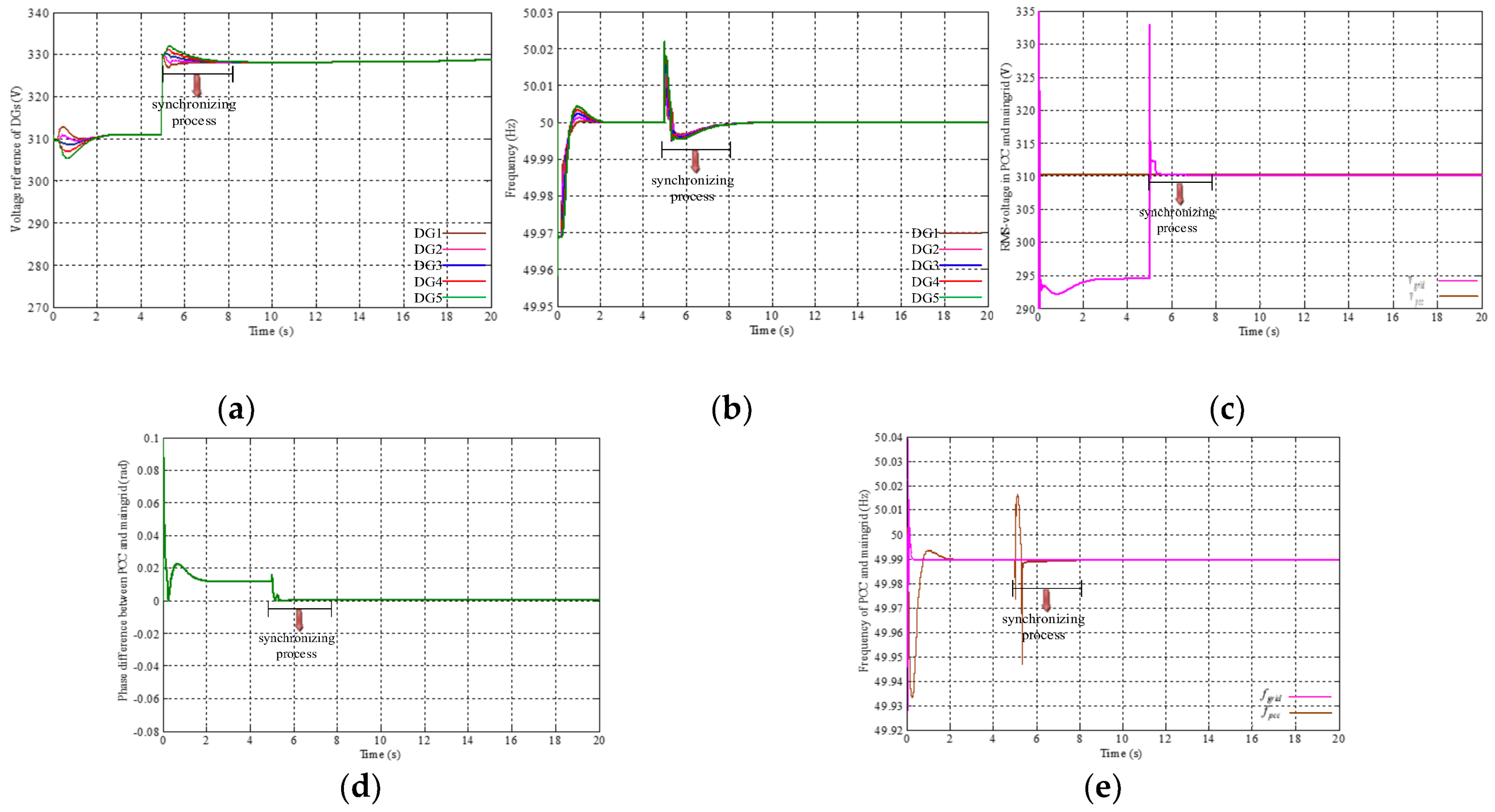
4.3. Case 3: Simulation Results of Seamless Handover from the Islanded Mode to the Grid-Connected Mode

Because the microgrid can be controlled in the grid-connected, islanded, and synchronizing modes, every DG in the microgrid should obtain its own operating mode by properly choosing the appropriate algorithm. When a master DG receives a grid-connect signal, because the frequency, voltage, and phase of the microgrid in the PCC are inconsistent with the main grid, the microgrid system should first enter the synchronizing mode. During the process of synchronization for DGs, the microgrid must meet the following synchronization criterion in the IEEE Standard 1547-2003 for the 0–500 kVA rated capacity [32,34,35].
{ | f m a i n g r i d f p c c | 0.05   Hz | v m a i n g r i d v p c c | 0.03   pu | φ m a i n g r i d φ p c c | 0.0175 ( 1 ° )
In this case, the simulation is performed in the conditions of the synchronizing mode and the grid-connected mode. When t < 5 s, the system is in the islanded mode. At t = 5 s, the system receives the instruction that the microgrid needed to connect to the main grid from an upper controller, and then the microgrid system enters the synchronizing mode. When the microgrid system meets the above three conditions in (33) and lasts at least 200 ms, the system can be connected to the grid. Figure 7a–e show the simulation results from the islanded mode to the grid-connected mode.

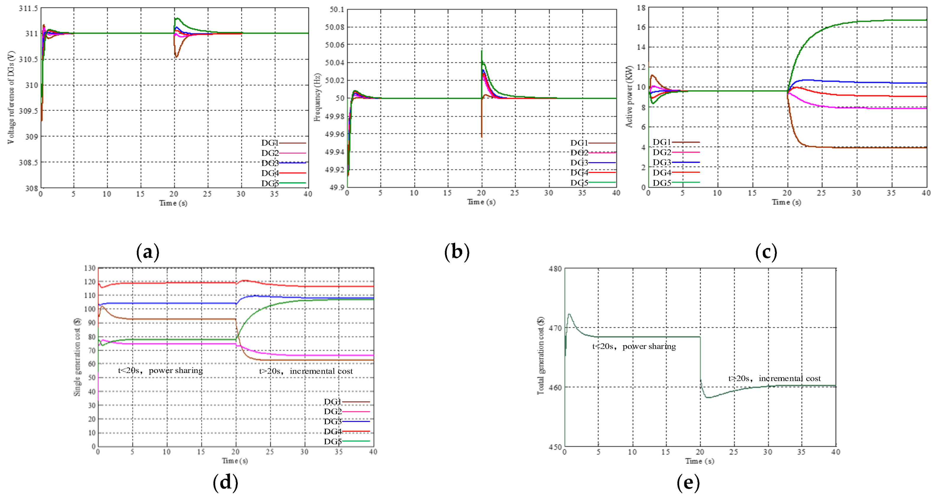
4.4. Case 4: Cost Comparison for Different Control Strategy

In this simulation, we compared the power sharing method and the economical method proposed in this paper. From Figure 8d,e, it is evident that the power generation cost is reduced under the proposed control method, and Figure 8a–c show the voltage-frequency and active power dynamic process under different control strategies.

4.5. Case 5: Simulation Results with Communication Failure

The problem of communication failure often occurs in practical application scenarios. However, the microgrid system should keep stable in this condition. The proposed method well deals with the situation. In this case, this simulation is divided into three stages.
Stage 1: When t ≤ 20 s, similar to case 2, the system quickly converges to the steady state.
Stage 2: Supposing the system is suffered with a weak communication failure when t > 20 s, that is the communication topology changes from the undirected ring connection to the directed connection, and the Laplacian matrix of communication topology is as follows:
L = [ 2 1 0 0 1 1 2 1 0 0 0 1 2 1 0 0 0 1 2 1 1 0 0 1 2 ] t > 20 s [ 1 0 0 0 1 1 1 0 0 0 0 1 1 0 0 0 0 1 1 0 0 0 0 1 1 ]
As long as the communication system keeps strongly connected, the microgrid system still realizes voltage-frequency synchronization and economic optimization. From Figure 9a–c show the simulation results, which state clearly that the microgrid system tends to be consistent after a slight shock under the proposed control method.
Stage 3: Supposing the system suffers a severe disruption of communication when t > 40 s, then the system is automatically converted into a decentralized mode. The droop coefficients of DGs are maintained at the value before the communication failure and the deviation signals Δfe and Δve cannot be sent to the follower DGs. At this moment, the voltage and frequency oscillate slightly but quickly tend to stable only when the load demand is constant. Figure 9a–c clearly show this condition, which means the proposed distributed secondary control algorithm is robust against system communication failure.

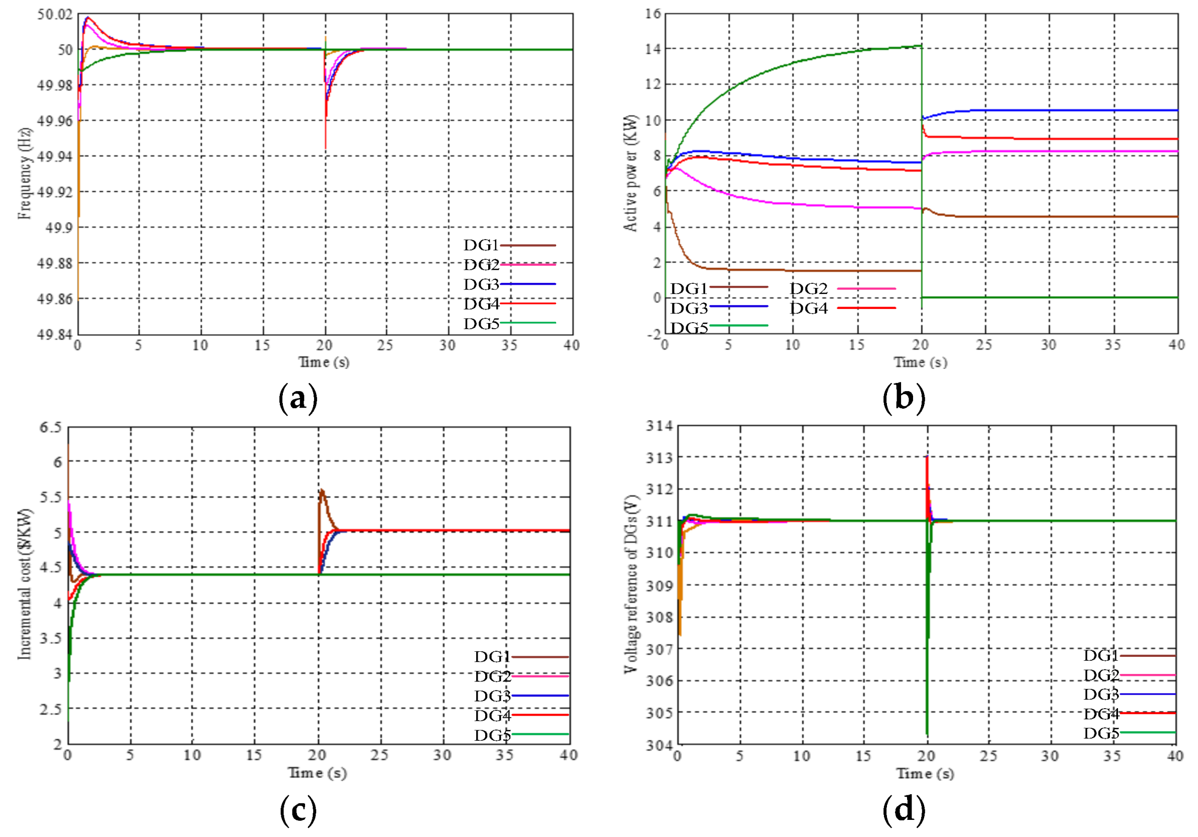
4.6. Case 6: Simulation Results of Plug-and-Play Function

In the last simulation, the key feature of plug-and-play in the microgrid is considered. Supposing that DG5 is set out of service because of some reasons at t > 20 s; thus the Laplacian matrix of communication topology is changed to be:
L = [ 2 1 0 0 1 1 2 1 0 0 0 1 2 1 0 0 0 1 2 1 1 0 0 1 2 ] t > 20 s [ 1 1 0 0 1 2 1 0 0 1 2 1 0 0 1 1 ]
Figure 10a–d display the plug-and-play function of the proposed control method. As shown in the figure, when DG5 is drop out from the microgrid at t = 20 s, DG1~4 remain to provide the power to satisfy the load demand. The remaining DGs can redistribute the load power and make the incremental cost λ1~λ4 tend a new optimal incremental cost according to the Theorem 2 and Equations (21)–(23).

5. Conclusions and Future Work

In this study, we developed a distributed secondary control strategy for voltage-frequency recovery and EDP. The control algorithms are based on an undirected ring network with a leader DG. Compared with the existing control strategy, the proposed control algorithm is fully distributed, which can realize the synchronization of voltage-frequency by exchanging additional signals Δf and Δv with neighboring units. The proposed distributed control algorithm can effectively avoid the communication fault situation, which has important practical significance. In addition, this method can also be applied in the grid-connected mode and the synchronizing mode, but in those cases, E* and f* are replaced by the voltage and frequency of the critical point. Moreover, in this paper, a strict proof is presented and some cases are also provided to illustrate the proposed control algorithm in detail.
However, there are still many issues to consider and solve. For instance, case 2 demonstrates the output under the condition of generator constraint. When t > 20 s, DG2 reaches its maximum value of 10 KW, and there is no increase in its active power output. Here the DG2 should change control strategy from droop control strategy to PQ control strategy. As for when and how to change control strategy, it is worth to further study and discussion. We only discuss the voltage-frequency recovery algorithm under inductive line impedance in this paper. However, lower X/R ratio leads to strong coupling of the active power and reactive power, and the method of realizing voltage-frequency recovery by a more universal distributed method is worth further study in future work.

Acknowledgments

The author would like to thank the supervisor, Mi Dong, the Power Electronics and Renewable Resource Research Institute, for supporting this work by the National Natural Science Foundation of China (No. 51677194).

Author Contributions

All the authors contributed to this work. Li Li designed the study, performed the analysis, implemented simulations, and wrote the first draft of the paper. Mi Dong and Lina Wang set the simulation environment, and checked the overall logic of this work. Dongran Song, Zhangjie Liu and Xiaoyu Tian contributed to providing important comments on the modeling and thoroughly revised the paper. Zhengguo Li and Yinghua Wang reviewed the work and gave helpful suggestions for English grammar.

Conflicts of Interest

The authors declare no conflict of interest.

References

  1. Keyhani, A.; Marwali, M. Smart Power Grids, 1st ed.; Springer: Berlin/Heidelberg, Germany, 2011; pp. 25–27. [Google Scholar]
  2. Song, D.; Yang, J.; Fan, X.; Liu, Y.; Liu, A.; Chen, G.; Joo, Y.H. Maximum power extraction for wind turbines through a novel yaw control solution using predicted wind directions. Energy Convers. Manag. 2018, 157, 587–599. [Google Scholar] [CrossRef]
  3. Song, D.; Yang, J.; Cai, Z.; Dong, M.; Joo, Y.H. Model predictive control with finite control set for variable-speed wind turbines. Energy 2017, 126, 564–572. [Google Scholar] [CrossRef]
  4. Liang, H.; Zhuang, W. Stochastic Modeling and Optimization in a Microgrid: A Survey. Energies 2014, 7, 2027–2050. [Google Scholar] [CrossRef]
  5. Han, H.; Hou, X.; Yang, J.; Wu, J.; Su, M.; Guerrero, J.M. Review of power sharing control strategies for islanding operation of AC microgrids. IEEE Trans. Smart Grid 2016, 7, 200–215. [Google Scholar] [CrossRef]
  6. Qiu, J.; Zhao, J.; Wang, D.; Zheng, Y. Two-Stage Coordinated Operational Strategy for Distributed Energy Resources Considering Wind Power Curtailment Penalty Cost. Energies 2017, 10, 965. [Google Scholar] [CrossRef]
  7. Palizban, O.; Kauhaniemi, K. Hierarchical control structure in microgrids with distributed generation: Island and grid-connected mode. Renew. Sustain. Energy Rev. 2015, 44, 797–813. [Google Scholar] [CrossRef]
  8. Li, Z.; Zang, C.; Zeng, P.; Yu, H.; Li, S. Fully distributed hierarchical control of parallel grid-supporting inverters in islanded AC microgrids. IEEE Trans. Ind. Inform. 2018, 14, 679–690. [Google Scholar] [CrossRef]
  9. Zhao, Z.; Yang, P.; Guerrero, J.M.; Xu, Z.; Green, T.C. Multiple-Time-Scales Hierarchical Frequency Stability Control Strategy of Medium-Voltage Isolated Microgrid. IEEE Trans. Power Electron. 2016, 31, 5974–5991. [Google Scholar] [CrossRef]
  10. Xiao, Z.; Li, T.; Huang, M.; Shi, J.; Yang, J.; Yu, J.; Wu, W. Hierarchical MAS Based Control Strategy for Microgrid. Energies 2010, 3, 1622–1638. [Google Scholar] [CrossRef]
  11. D’Arco, S.; Suul, J.A. Equivalence of virtual synchronous machines and frequency-droops for converter-based microgrids. IEEE Trans. Smart Grid 2014, 5, 394–395. [Google Scholar] [CrossRef]
  12. Sun, Y.; Hou, X.; Yang, J.; Han, H.; Su, M.; Guerrero, J.M. New Perspectives on Droop Control in AC Microgrid. IEEE Trans. Ind. Electron. 2017, 64, 5741–5745. [Google Scholar] [CrossRef]
  13. Lu, Q.; Hu, W.; Zheng, L.; Min, Y.; Li, M.; Li, X.; Ge, W.; Wang, Z. Integrated Coordinated Optimization Control of Automatic Generation Control and Automatic Voltage Control in Regional Power Grids. Energies 2012, 5, 3817–3834. [Google Scholar] [CrossRef]
  14. Lopes, J.A.P.; Moreira, C.L.; Madureira, A.G. Defining control strategies for microgrids islanded operation. IEEE Trans. Power Syst. 2006, 21, 916–924. [Google Scholar] [CrossRef]
  15. Shafiee, Q.; Guerrero, J.M.; Vasquez, J. Distributed Secondary Control for Islanded Microgrids—A Novel Approach. IEEE Trans. Power Electron. 2014, 29, 1018–1031. [Google Scholar] [CrossRef]
  16. Guo, F.; Wen, C.; Mao, J.; Song, Y.D. Distributed secondary voltage and frequency restoration control of droop-controlled inverter-based microgrids. IEEE Trans. Ind. Electron. 2015, 62, 4355–4364. [Google Scholar] [CrossRef]
  17. Rokrok, E.; Shafie-khah, M.; Siano, P.; Catalão, J.P.S. A Decentralized Multi-Agent-Based Approach for Low Voltage Microgrid Restoration. Energies 2017, 10, 1491. [Google Scholar] [CrossRef]
  18. Pilloni, A.; Pisano, A.; Usai, E. Robust Finite-Time Frequency and Voltage Restoration of Inverter-Based Microgrids via Sliding-Mode Cooperative Control. IEEE Trans. Ind. Electron. 2018, 65, 907–917. [Google Scholar] [CrossRef]
  19. Tan, K.; Peng, X.; So, P.; Chu, Y.; Chen, M. Centralized control for parallel operation of distributed generation inverters in microgrids. IEEE Trans. Smart Grid 2012, 3, 1977–1987. [Google Scholar] [CrossRef] [Green Version]
  20. Ahn, C.; Peng, H. Decentralized and real-time power dispatch control for an islanded microgrid supported by distributed power sources. Energies 2013, 6, 6439–6454. [Google Scholar] [CrossRef]
  21. Yan, B.; Wang, B.; Zhu, L.; Liu, H.; Liu, Y.; Ji, X.; Liu, D. A novel, stable, and economic power sharing scheme for an autonomous microgrid in the energy internet. Energies 2015, 8, 12741–12764. [Google Scholar] [CrossRef]
  22. Han, H.; Li, L.; Wang, L.; Su, M.; Zhao, Y.; Guerrero, J.M. A Novel Decentralized Economic Operation in Islanded AC Microgrids. Energies 2017, 10, 804. [Google Scholar] [CrossRef]
  23. Zhang, Z.; Chow, M.-Y. Convergence analysis of the incremental cost consensus algorithm under different communication network topologies in a smart grid. IEEE Trans. Power Syst. 2012, 27, 1761–1768. [Google Scholar] [CrossRef]
  24. Chen, G.; Lewis, F.L.; Feng, E.N.; Song, Y. Distributed optimal active power control of multiple generation systems. IEEE Trans. Ind. Electron. 2015, 62, 7079–7090. [Google Scholar] [CrossRef]
  25. Yang, Z.; Xiang, J.; Li, Y. Distributed Consensus Based Supply–Demand Balance Algorithm for Economic Dispatch Problem in a Smart Grid with Switching Graph. IEEE Trans. Ind. Electron. 2017, 64, 1600–1610. [Google Scholar] [CrossRef]
  26. Jalilzadeh Hamidia, R.; Livania, H.; Hosseinianb, S.H.; Gharehpetianb, G.B. Distributed cooperative control system for smart microgrids. Electr. Power Syst. Res. 2016, 130, 241–250. [Google Scholar] [CrossRef]
  27. Mashhour, E.; Moghaddas-Tafreshi, S.M. Bidding strategy of virtual power plant for participating in energy and spinning reserve markets—Part I: Problem formulation. IEEE Trans. Power Syst. 2011, 26, 949–956. [Google Scholar] [CrossRef]
  28. Gozde, H.; Taplamacioglu, M.E. Automatic generation control application with craziness based particle swarm optimization in a thermal power system. Int. J. Electr. Power Energy Syst. 2011, 33, 8–16. [Google Scholar] [CrossRef]
  29. Liu, Z.; Su, M.; Sun, Y.; Han, H.; Hou, X.; Guerrero, J.M. Stability analysis of DC microgrids with constant power load under distributed control methods. Automatica 2018, 90, 62–72. [Google Scholar] [CrossRef]
  30. Xin, H.; Lu, Z.; Qu, Z.; Gan, D.; Qi, D. Cooperative control strategy for multiple photovoltaic generators in distribution networks. IET Control Theory Appl. 2011, 5, 1617–1629. [Google Scholar] [CrossRef]
  31. Sun, Y.; Zhong, C.; Hou, X.; Yang, J.; Han, H.; Guerrero, J.M. Distributed cooperative synchronization strategy for multi-bus microgrids. Electr. Power Energy Syst. 2017, 86, 18–28. [Google Scholar] [CrossRef]
  32. Nasirian, V.; Davoudi, A.; Lewis, F. Distributed adaptive droop control for DC distribution system. IEEE Trans. Energy Convers. 2014, 29, 944–956. [Google Scholar] [CrossRef]
  33. Han, H.; Wang, H.; Sun, Y.; Yang, J.; Liu, Z. Distributed control scheme on cost optimisation under communication delays for DC microgrids. IET Gener. Trans. Distrib. 2017, 11, 4193–4201. [Google Scholar] [CrossRef]
  34. Li, Z.; Duan, Z.; Chen, G.; Huang, L. Consensus of multiagent systems and synchronization of complex networks: A unified viewpoint. IEEE Trans. Circuits Syst. I 2010, 57, 213–224. [Google Scholar]
  35. Chatterjee, S.; Kumar, P.; Chatterjee, S. A techno-commercial review on grid connected photovoltaic system. Renew. Sustain. Energy Rev. 2018, 81, 2371–2397. [Google Scholar] [CrossRef]
Figure 1. The workflow of secondary AGC and AVC.
Energies 11 00932 g001
Figure 2. Two-layer structure for an alternating current (AC) microgrid.
Energies 11 00932 g002
Figure 3. The calculation process of the optimal incremental cost with power constraint.
Energies 11 00932 g003
Figure 4. The supply and demand under different communication speed. (a) Sampling time T = 0.1 s. (b) Sampling time T = 0.001 s. (c) Cost under different sampling time.
Energies 11 00932 g004
Figure 5. Simulation results of voltage-frequency recovery and synchronization. (a) Voltage; (b) Frequency.
Energies 11 00932 g005
Figure 6. Simulation results with load changing. (a) Voltage reference of DGs. (b) Frequency of DGs. (c) Active power of DGs. (d) Incremental cost λ. (e) Total active power.
Energies 11 00932 g006
Figure 7. Simulation results of synchronizing mode. (a) Voltage reference of distributed generators (DGs). (b) Frequency of DGs. (c) Voltage of main grid and point of common coupling (PCC). (d) Phase angle difference of main grid and PCC. (e) Frequency of main grid and PCC.
Energies 11 00932 g007
Figure 8. Total generation cost under different control strategies. (a) Voltage reference of DGs. (b) Frequency of DGs. (c) Active power of DGs. (d) Single generation cost. (e) Total generation cost.
Energies 11 00932 g008
Figure 9. Simulation results with communication failure. (a) Frequency; (b) Active power; (c) Incremental cost λ.
Energies 11 00932 g009
Figure 10. Simulation results of plug-and play function. (a) Frequency; (b) Active power; (c) Incremental cost λ; (d) Voltage reference of DGs.
Energies 11 00932 g010
Table 1. Specifications of the microgrid system.
NameParametersDG1–5
P-f droop coefficientmref10−5 (Hz/W)
Q-V droop coefficientnref10−3 (V/Var)
Voltage deviation proportional termkpvs10
Voltage deviation integral termkivs0.1
Frequency deviation proportional termkpfs5
Frequency deviation integral termkifs0.1
Power deviation proportional termkpps0.05
Distributed cooperative voltage gainkv150
Distributed cooperative frequency gainkf5
Distributed cooperative incremental gainkλ5
Voltage proportional termkpv0.0015
Voltage integral termkiv4
Current proportional termkpi4
Table 2. Coefficient of cost function for the microgrid system.
UnitCoefficient of Cost FunctionPimin (KW)Pimax (KW)
αiβiγi
DG10.0874.1345010
DG20.0763.6233010
DG30.0753.2566015
DG40.1122.7882020
DG50.0981.5454040

