Abstract
Energized insulator’s surface contamination is greatly affected by its electric field properties. However, few reports about the electric field influencing mechanism on the pollution deposition have been presented. In this paper, the coupling-physics model of a three-unit XP-160 insulator string was established, and the particles’ deposition process was simulated by using the finite element method. The effects of the electric field on the pollution particles’ motion were analyzed. Research results indicate that the closer to the insulator string, the larger the intersection angle θ between the electric force and its horizontal component. The main function of the electric field on insulator contamination is that it changes the pollution particles’ vertical moving speed, thus accelerating the particles’ deposition process. The particle capture coefficient ratio ck can be used to reflect the pollution degree discrepancy between DC-energized and non-energized insulators. In this paper the ratio ck of the DC-energized to non-energized condition is in the range of 1.04 to 1.98, very close to the field measurement results of the DC pollution ratio k.
1. Introduction
Due to the deterioration of the atmospheric environment in China, operating HVDC transmission lines are still under risk of pollution flashover accidents [1,2]. Pollution-induced flashover of insulators is a serious threat to safe power grid operation. It will cause large-scale power supply outages and badly impact social economic development [3]. The primary cause of pollution flashover is contamination accumulation and deposition on insulator surfaces. It is still important to study the insulator contamination rules to better guide the anti-pollution work of transmission line external insulation.
Plenty of studies on insulator contamination mechanisms have been conducted by researchers through applying commercial simulation packages or conducting laboratory experiments. Ravelomanantsoa and Farzaneh et al. [4] put forward a power law relation between the pollution accumulation rate and the wind velocity using a simplified wind tunnel contamination platform. Sun et al. [5] built a pollution deposition model for rail insulators, and carried out gas–solid aerosol flow simulations to show the rules of wind velocity affecting pollution deposition and distribution. To obtain the pollution accumulation influencing factors, Zhang et al. [6] analyzed the airflow field distribution and particle collision coefficient around an insulator through dynamic fluid simulation. They also studied the relationships among the particle phase volume fraction, wind velocity, particle diameter, insulator surface pollution degree, and distribution by using the Euler-Euler multiphase simulation method [7].
It is commonly known that due to electrostatic force, the direct current (DC) electric field aggravates the insulator’s pollution degree more seriously than alternating current (AC) does [8]. Therefore, some studies about DC electric field effects were also reported. Through laboratory experiments, Horenstein et al. [9] proposed that only the electric field between sheds will rotate the particle’s motion. For particles within 1–10 μm, their trajectories are determined by electrostatic force, while, for those over 10 μm, the trajectories are affected by air drag force. Lu et al. [10] concluded that the DC voltage results in a larger contaminant deposition rate of particles on the insulator surface than AC voltage and non-energized conditions. Wu et al. [11] studied the pollution depositing characteristic of roof insulators under a high-speed flow and determined that the influence of the electric field force is far less than the air drag force. In addition to these, some field pollution tests on energized and non-energized insulators operating in transmission lines were also carried out [12,13], which also showed that DC lines’ insulators collect more pollution than AC lines.
Those studies above presented essential references for the insulator pollution deposition performances. However, few of them provided quantitative analysis of the electric field influencing mechanism on insulator pollution accumulation processes; they just made some general descriptions based on experimental results. Explanations of how the electric force imposes on pollution particles, and to what percent it aggravates the pollution degree, are still missing.
This paper built a simulation model which combined electric and airflow fields. Through this model the particles’ motion towards the insulator surface were simulated. The effects of the DC electric field on pollution particles’ deposition under different particle diameters and wind speed conditions were analyzed. The particle capture coefficient ratio ck was proposed for representing the DC line pollution severity, and it was also verified by field pollution degree experiments. Research results are valuable for pollution level mapping works and the external insulation design of DC lines.
2. Analysis of Insulator String Electric Field and Electric Force
2.1. Electric Field Simualtion
In this paper a three-unit typical type XP-160 (NGK, Osaka, Japan) insulator string was taken as the sample. The COMSOL software package (Version 4.4, COMSOL Inc., Stockholm, Sweden) was used to solve the electric field distribution around the insulator string. COMSOL is a powerful software package which can compute multiphysics coupling issues using the finite element method. The governing equation for the DC electric field computational domain is as follows [10]:
where E is the electric field intensity, in V/m; D is the electric displacement stress, in C/m2; U is the electric potential, in Volts; ε0 is the vacuum permittivity, set as 8.85 × 10⁻¹² F/m in this paper; ε1 is the relative permittivity (for porcelain it is 6 in this paper); and ρ is the density of volume charges, in C/m3.
The 3-D simulation model was established according to the structure parameters of a real-scale insulator, as is shown in Table 1.

Table 1.
Structural parameters of the insulators.
The whole computation area is treated as an ideally dry condition, so the surface conductivity caused by conductive components of the contaminants was not considered by this paper. In this case the porcelain insulators were treated as an ideal insulating material.
An artificial rectangle boundary was added far away from the insulator string in the simulation model. The electric potential of the boundary was set as 0, regarded as the zero potential reference point of infinite area. Chao et al. [12] concluded that the polarity effect on DC energized insulator contamination can be neglected, so only the positive DC condition is discussed in this paper. According to the operating experience of ±500 kV transmission lines in China, the withstood gradient of insulation height should be over 70 kV/m [14], which means that for each XP-160 (NGK, Osaka, Japan) insulator unit, it needs to withstand at least 11 kV to ensure the insulation strength. Considering this, the high-voltage terminal of the insulator string was set as +35 kV during the simulation, as is shown in Figure 1a. Simulation results of the electric field around insulator string are shown in Figure 1b.
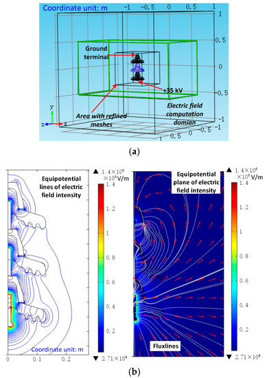
Figure 1.
Simulation of the electric field around the insulator string. (a) Schematic diagram of the 3D model of the electric field simulation; (b) Electric field simulation results.
It can be seen from Figure 1b that the electric field distributes non-uniformly around insulator string. The maximum value of electric field intensity, which is about 1.4 × 10⁶ V/m, is generated at the pin surface of the high-voltage terminal, and then it drops rapidly to 6 × 10⁵ V/m or lower. The lowest electric field intensity value is 2.7 × 10⁴ V/m. The flux lines, as well as the directions of the electric field, are also shown in Figure 1b. The arrows are marked just for the purpose of showing the flux line directions, so their lengths are normalized. It can be seen that the electric flux lines start from the high-voltage terminal and point to the ground terminal along the insulator’s surfaces.
2.2. Electric Force Calculation
In the real natural atmosphere, a certain amount of air ions exists in a dynamic balancing state and, commonly, the concentration of aero-cations is 1.1–1.4 times higher than that of aero-anions [15,16]. Aero ions’ motion will charge neutral dust flowing in the space. Experiments by White [17] showed that 31% of atmospheric particles are positively charged, 43% are uncharged, and 26% are negatively charged. In DC lines, the aero ions around an energized insulator string will move vigorously due to the electric field and frequently collide with neutral particles in the air flow, making them charged. Then, the charged particles will move towards the positive or negative electrode by electric force. This is the so-called electrical charge process, which is applicable for particles over 1 μm in diameter (dp).
During the electrical charge process, the particle’s charge quantity increases, and an electric field with the direction opposite to the outer one will form around particle surface. This electric field will become more and more intensive and finally make ions unable to approach the particle’s surface. In this case, the particle’s charge quantity gets saturated. The pollution particle’s saturated charge quantity can be expressed by:
where Qp is the particle’s saturated charge quantity; ρp is particle’s mass density, and for SiO2 it is 2320 kg/m3 in this paper; dp is the particle diameter, in m; ε0 is the vacuum permittivity, set as 8.85 × 10⁻¹²; and εp is the relative permittivity of pollution particle, and for SiO2 it is 4.5. Then the electric force applied on pollution particle can be calculated by:
where E is the electric field intensity in the space, in V/m.
Taking the negatively-charged particles as example, we analyze the electric force characteristics applied to the particles when they approach the surface of the second insulator unit. As is shown in Figure 2, P1P2 is a path that from outer space to the insulator surface. The axis unit is in m. In the figure, Fe, Feh, and Fev are the electric force, the electric force’s horizontal component, and the vertical component, respectively, in N. θ is the intersection angle between the electric force and its horizontal component.
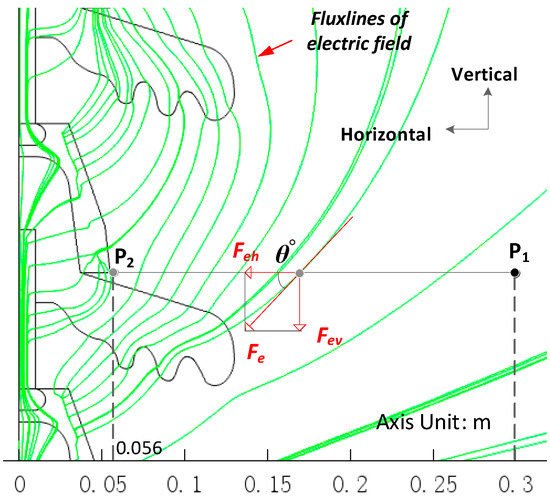
Figure 2.
Diagram of the sampled path near the insulator string.
From the electric field flux lines in Figure 2 it can be seen that in the path P1P2 the negatively-charged particles tend to move toward the insulator cap and top surface. Simulation results of the electric force distribution on path P1P2 are shown in Figure 3. The values were scaled linearly using JET colormap.
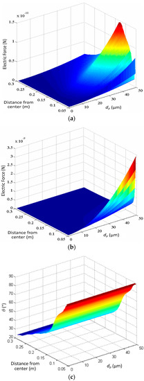
Figure 3.
Electric field force performance near the insulator string. (a) The horizontal component of electric force; (b) The vertical component of electric force; and (c) θ°, the angle between of electric force and horizontal direction.
It can be seen from the figure that the horizontal component of the electric force around the insulator surface is within 1.4 × 10⁻¹⁴ N to 1.4 × 10⁻¹⁰ N, while the vertical component is within 5.3 × 10⁻¹⁵ N–3.4 × 10⁻⁹ N. The vertical component of the electric force is obviously larger than the horizontal component when the distance is within 0.15 m. For particles with diameters over 20 μm, the electric force increases greatly with dp. θ° is within 23–89° in that path, and the closer to the insulator surface, the larger the angle, meaning that the electric force is almost in the vertical direction, making particles deposit more easily in that direction.
3. Effects of the DC Electric Field on the Pollution Particle’s Motion
Using the COMSOL multiphysics package to simulate the coupling function of electric field and air flow field, and track the particles’ trajectories when forced by air drag, gravity, and electric force. The particles are regarded as spherical with uniform density, so the air drag force and gravity imposed on pollution particles can be calculated as follows:
where Fg is the gravitational force of the particle, Fd is the drag force caused by air flow, vc is the velocity of the flow field, vp is the velocity of pollution particle, and μ is the dynamic viscosity of the air.
Suppose that the particles stop moving when they reach the insulator surface. The insulator surface was set as an interior wall with a “freezing” boundary, so the end speed and motion trajectories of particles can be recorded. Setting the wind is in horizontal direction, and the initial velocity of particles is 0, taking air flow velocity vc = 1 m/s, particle diameter dp = 20 μm as the example, the simulation results of particles’ trajectories are shown in Figure 4.
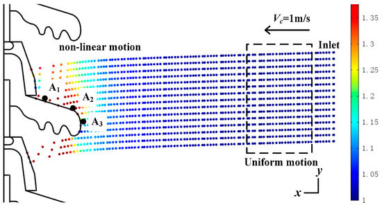
Figure 4.
Particle trajectory when moving through the airflow field and the electric field around an insulator.
It can be seen from Figure 4 that, at the beginning, the air flow field has the major influence on particle motion, and the pollution particle is imposed by the equilibrium forces of air drag and gravity, under which it moves straight towards the insulator surface with an almost constant velocity (1 m/s in x direction, −0.016 m/s in y direction). However, when getting close to the insulator string, the motion trajectories become non-linear, and the particles accelerate their motion to deposit onto the top insulator surface. This is caused by the electric force.
We investigated the effect of the electric field on the particles’ motion ability. The sample points were set as A1, A2, A3, which represent different locations on the insulator surface, as shown in Figure 4. Calculating the changing rate Δvp of the pollution particle velocity caused by the electric field, Δvp is expressed as follows:
where vp0 is the end speed of the pollution particle when the insulator string is non-energized; vpe is the end speed of the pollution particle when the insulator string is energized with +35 kV DC. The velocity changing rates under different wind speeds and particle diameters calculated by Equation (6) are shown in Figure 5. In Figure 5, Δvpx and Δvpy are, respectively, the horizontal and vertical components of ΔVp.
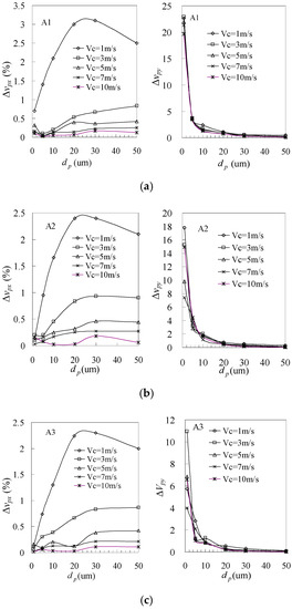
Figure 5.
The variation of particle velocity affected by electric force. (a) Position A1; (b) Position A2; (c) Position A3.
It can be seen from Figure 5 that:
- (1)
- Under DC electric field, their horizontal moving speed vpx does not change much, the increasing rate is only within 5%. The lower the wind speed, the higher the Δvpx values of particles. This is mainly because when wind velocity is low, the function of air drag force on the particles is weakened, in which case the electric force is relatively distinct and easily accelerates the particle motion.
- (2)
- Particles’ vertical velocity component is greatly affected by the DC electric field. The vertical component of the end speed increased by 0.5–23 times when dp is within 1–50 μm, obviously higher than that of the horizontal component. The smaller the particle diameter, the more outstanding the particle velocity increases in the vertical direction. The increasing rate drops rapidly when dp increases from 1 to 20 μm, and then remains gentle. This is mainly because gravity is proportional to the third power of dp, while the electric force is proportional to the square of dp.
- (3)
- The end speed of particles moving across electric field is associated with the colliding position. The increasing rate of the particles’ end speed is higher if the colliding position is closer to the insulator string (such as A1). This is because it takes a longer time and distance for particles to get closer to the insulator string, in which case the electric force will have a greater effect on the particles’ motion.
The effects of electric field on pollution deposition are now reflected by the particles motion properties as shown above. In summary, the main function of the electric field during insulator contamination is that it changes the particles’ vertical motion, especially when dp is within 1–20 μm. Thus, DC electric fields will cause negative particles to accelerate their deposition on the insulator top surface as previously analyzed. This can be detected in the opposite way, in that the electric force will also attract more positive particles moving toward the insulator bottom surface, thus benefiting insulator contamination.
4. Effects of DC Electric Field on the Insulator Pollution Degree
The analysis above explained the effects of electric field on pollution particle deposit process. This section presents field experiments, as well as the simulation results showing the increment of the insulator pollution degree under a DC field.
Currently, a general method for determining the pollution levels of transmission lines is by measuring the pollution degree of non-energized reference insulators suspended on the tower. In this way the site pollution severity (SPS) of certain areas can be obtained without temporarily interrupting the power supply [18]. However, for DC lines, the pollution degree obtained from uncharged reference insulators needs to be multiplied by a DC pollution ratio k, which is defined as the ratio of pollution degree measured from DC-energized insulators to that measured from non-energized insulators [18]. k is associated with pollution particle diameter and wind velocity. According to limited wind tunnel tests, k is around 1.2–2.8 when dp is within 8–30 μm [18,19].
In this paper, the k values for a HVDC line were obtained through field pollution tests. The samples were typical-type suspension porcelain insulators arranged in three different towers from a ±800 kV HVDC line corridor located in a Central China city suburb. The tower views and a diagram of the test samples’ arrangement are shown in Figure 6. The arrangement of the samples and the pollution test procedures exactly followed the guidelines in [18].
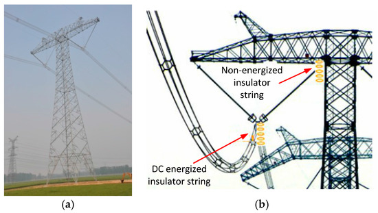
Figure 6.
Field pollution test of transmission line operating insulators. (a) The ±800 kV transmission line view; (b) Diagram of the insulator string samples’ arrangement.
The DC-energized string was made up of three insulator units, and only the middle unit’s pollution degree was measured following the guidelines in [18]. The non-energized contamination sample was a 14-unit insulator string, and the pollution degree average value of the middle 12 units was measured.
The contamination period was from September 2015 to September 2016. According to the meteorological monitoring statistics near that location, the frequency of the wind speed within 0.6–5.4 m/s reaches 95% during that one-year contamination. Based on the TSP (total suspended particles) monitoring data near that area, the cumulative probability of particles dp ≤ 50 μm is about 90%.
Following the guidelines in [18], ESDD (equivalent salt deposit density, mg/cm2), and NSDD (non-soluble pollution deposit density, mg/cm2) of the samples were measured based on the method shown in Figure 7: firstly, moderately purified water was used to clean up the surface of the polluted insulator, then the conductivity of the dirty liquid after filtering was measured, the salt quantity attached to the top or bottom surface of insulator was calculated separately and, finally, based on the areas of the top and bottom surface, the converse salt quantity to ESDD was calculated; the dirty liquid was filtered after cleaning the insulator, then the insoluble materials left on the filtering paper to dry and were weighed. Lastly, referring to the surface area, the converse of the quantity of insoluble materials to NSDD was calculated.

Figure 7.
The flowchart of the measuring of the ESDD and NSDD.
The test results of ESDD, NSDD, and the corresponding DC pollution ratios are shown in Table 2.

Table 2.
Pollution test results for field operating insulators.
It can be seen from the table that the DC pollution ratio k in the sampled area is around 1.24–1.58 by ESDD, and 0.81–1.69 by NSDD. The manual measurement error during pollution collection may be the reason for the k value by NSDD of tower no. 2 being lower than 1. Regardless, the k for the sampled transmission line areas is within 1.2–1.7 in general.
The measurement of k is a complicated work which needs plenty of manpower. However, by using the simulation method, the factors of particle diameter, wind velocity, and electric field can be included. This may be a useful manner for obtaining the DC pollution ratio k without any time-consuming, dangerous, and sometimes irregular field pollution measurements.
Particles touching the insulator surface are the precondition for pollution accumulation. By setting the insulator surface wall as “trap” boundary during the simulation, the amount of particles that arrive upon the insulator surface after moving through an airflow and electric field can be recorded and, thus, the insulator surface pollution situation can be reflected. In this paper, the particle capture coefficient Cp is defined as follows:
where Ns is the particles’ amount which trapped by insulator surfaces, Nt is the particles’ total amount fed from the inlet. The diagram for computing Cp is shown in Figure 8.
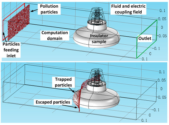
Figure 8.
Diagram for Cp computation (the coordinate unit is by meter).
Then the discrepancy of insulator surface pollution with and without a DC electric field can be expressed by:
where Cp_dc is the particle capture coefficient of the insulator string when considering the electric force; Cp_n is the particle capture coefficient without the electric force; and ck is their proportionality ratio, namely the particle capture coefficient ratio.
During the simulation, the air flow field was computed using the incompressible viscous steady-state fluid-simulated RANS k-ε model in [18], and the electric field was simulated as the procedure presented in Section 2. To equivalently re-produce the field arrangement of insulator samples on the tower, the electric potential settings was as shown in Figure 9. The concentration ratio of positive particles to negative particles fed from inlet was set as 1.1. The electric force was calculated using Equation (2).
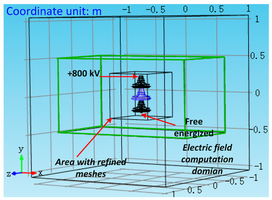
Figure 9.
Electric field simulation diagram for the transmission line insulator sample (the coordinates are by meter).
To be consistent with the field pollution test, only the ck of the second unit insulator was calculated. Through numerous simulations, ck values under different wind velocity VC and particle diameter dp are obtained, as is shown in Table 3.

Table 3.
Calculation results of particle capture coefficient ratio.
It can be seen from Table 3 that:
- (1)
- The ratio ck presents a decreasing trend with the increment of wind speed, which means the higher the wind speed, the weaker the DC electric field aggravating pollution degree. This is due to higher wind speed, resulting in larger air drag force, which obscures the electric field force.
- (2)
- Additionally, the ratio ck varies obviously with particle diameter dp. The value of the particle capture coefficient ratio ck when dp is 50 μm is always the lowest compared to other conditions (dp = 1 μm, 5 μm, 10 μm, 20 μm), meaning that the DC electric field has less of an effect on the pollution increment when the particle diameter is larger, which is in good accordance with previous analyses. Combined with the results shown in Figure 5, it can be deduced that the critical particle diameter when the air flow field controls the pollution particle deposition more than the DC electric field may be close to 20 μm.
- (3)
- The particle capture coefficient ratio ck is in the range of 1.04 to 1.98 when dp is within 1–50 μm and the wind velocity within 1–5 m/s, very close to the field measurement results of the DC pollution ratio k (within 1.2–1.7), as shown in Table 2. In such a case ck can be used to reflect the pollution degree increment of insulators under DC. In this way the complicated field measurement work can be saved to some degree.
5. Conclusions
This paper presents the analysis of DC electric field effects on insulator pollution particle deposition, as well as the pollution degree. Conclusions can be made that:
- (1)
- The main function of the electric field on insulator contamination is that it changes the particles’ vertical motion during its deposition process from outside to the insulator’s surface, especially when dp is within 1–20 μm. The particle’s vertical speed can increase to 0.5–23 times by electric force, which significantly accelerates the particles’ deposition process and benefits contamination.
- (2)
- The particle capture coefficient ratio ck of DC to non-energized conditions is in the range of 1.04 to 1.98 when dp is within 1–50 μm and wind velocity is within 1–5 m/s, very close to the one-year period field test results of the DC pollution ratio k (within 1.2–1.7) for the ±800 kV line.
This research indicates that it is feasible to use the simulation method in this paper to obtain the pollution degree increment of DC transmission lines. Thus, the conclusions, as well as the proposed simulation method, may provide useful references for the pollution severity prediction of DC lines, and, thus, save complicated field measurement work in the future.
Acknowledgments
This work was supported by the Funds for Science and Technology Project of State Grid Corporation (CN: SGTYHT/ 14-JS-188, SGCQJX00YJJS1600265) and the National “111” Project (B08036). The authors thank all members of the external insulation research team in Chongqing University for their hard work to obtain the test data in this paper.
Author Contributions
Xingliang Jiang and Lichun Shu conceived and designed the experiments; Dongdong Zhang performed the experiments and simulations; Dongdong Zhang and Zhijin Zhang analyzed the data; Bin Wu contributed materials tools; Dongdong Zhang wrote the paper.
Conflicts of Interest
The authors declare no conflict of interest.
References
- Jiang, X.; Yuan, J.; Zhang, Z.; Hu, J.; Shu, L. Study on Pollution Flashover Performance of Short Samples of Composite Insulators Intended for ±800 kV UHV DC. IEEE Trans. Dielectr. Electr. Insul. 2007, 14, 1192–1200. [Google Scholar] [CrossRef]
- Lin, Y.; Hao, Y.P.; Li, L.C.; Zhao, Y.M. Comparison of pollution flashover performance of porcelain long rod, disc type, and composite UHVDC insulators at high altitudes. IEEE Trans. Dielectr. Electr. Insul. 2012, 19, 1053–1059. [Google Scholar]
- Baker, A.C.; Farzaneh, M.; Gorur, R.S.; Gubanski, S.M.; Hill, R.J.; Karady, G.G.; Schneider, H.M. Insulator selection for AC overhead lines with respect to contamination. IEEE Trans. Power Deliv. 2009, 24, 1633–1641. [Google Scholar] [CrossRef]
- Ravelomanantsoa, N.; Farzaneh, M.; Chisholm, W.A. A Simulation Method for Winter Pollution Contamination of HV Insulators. In Proceedings of the 2011 Electrical Insulation Conference (EIC), Annapolis, MD, USA, 5–8 June 2011; pp. 373–376. [Google Scholar]
- Sun, J.; Gao, G.; Zhou, L.; Wu, G. Pollution accumulation on rail insulator in high-speed aerosol. IEEE Trans. Dielectr. Electr. Insul. 2013, 20, 731–738. [Google Scholar]
- Zhang, Z.; Zhang, D.; Jiang, X.; Liu, X. Study on natural contamination performance of typical types of insulators. IEEE Trans. Dielectr. Electr. Insul. 2014, 21, 1901–1909. [Google Scholar] [CrossRef]
- Zhang, Z.; Zhang, W.; You, J.; Jiang, X.; Zhang, D.; Bi, M.; Wu, B.; Wu, J. Influence factors in contamination process of XP-160 insulators based on computational fluid mechanics. IET Gener. Transm. Distrib. 2016, 10, 4140–4148. [Google Scholar] [CrossRef]
- Lampe, W.; Höglund, T.; Nellis, C.; Renner, P.; Stearns, R. Long-term tests of HVDC insulators under natural pollution conditions at the Big Eddy Test Center. IEEE Trans. Power Deliv. 1989, 4, 248–259. [Google Scholar] [CrossRef]
- Horenstein, M.N.; Melcher, J.R. Particle Contamination of High Voltage DC Insulators below Corona Threshold. IEEE Trans. Dielectr. Electr. Insul. 1979, 16, 297–305. [Google Scholar] [CrossRef]
- Lv, Y.; Li, J.; Zhan, X.; Pang, G. A simulation study on pollution accumulation characteristics of XP13-160 porcelain suspension disc insulator. IEEE Trans. Dielectr. Electric Insul. 2016, 23, 2196–2206. [Google Scholar] [CrossRef]
- Wu, X.; Zhang, X.; Wu, G. Simulation and Analysis of Contamination Depositing Characteristic of Roof Insulator. In Proceedings of the 2016 IEEE International Conference on High Voltage Engineering and Application (ICHVE), Chengdu, China, 19–22 September 2016; pp. 1–4. [Google Scholar]
- Chao, Y.; Huang, F.; Zhao, S.; Wang, C.; Wang, F.; Yue, Y. Study on natural pollution accumulating characteristics of cap and pin suspension ceramic insulator with composite shed of DC 500 kV transmission line in central China. In Proceedings of the 2016 IEEE International Conference on High Voltage Engineering and Application (ICHVE), Chengdu, China, 19–22 September 2016; pp. 1–4. [Google Scholar]
- Liu, Q. Investigation on natural contamination deposition ofinsulators on ±500 kV DC transmission lines in different environments. In Proceedings of the 2013 Annual Report Conference on Electrical Insulation and Dielectric Phenomena, Shenzhen, China, 20–23 October 2013; pp. 347–349. [Google Scholar]
- Jiang, X.; Shu, L.; Sun, C. Power System Pollution and Iced Insulation; Chinese Electric Power Press: Beijing, China, 2009. (In Chinese) [Google Scholar]
- Jayaratne, E.R.; J-Fatokun, F.O.; Morawska, L. Air ion concentrations under overhead high-voltage transmission lines. Atmos. Environ. 2008, 42, 1846–1856. [Google Scholar] [CrossRef]
- Ling, X.; Jayaratne, R.; Morawska, L. The relationship between airborne small ions and particles in urban environments. Atmos. Environ. 2013, 79, 1–6. [Google Scholar] [CrossRef]
- White, H.J. Industrial Electrostatic Precipitators; Addison-Wesley: Boston, MA, USA, 1963. [Google Scholar]
- IEC 60815-4-2016. Selection and Dimensioning of High-Voltage Insulators Intended for Use in Polluted Conditions—Part 4: Insulators for d.c Systems; British Standards: London, UK, 2016. [Google Scholar]
- Su, Z.; Fan, J.; Gu, C.; Zhou, J. The research of pollution level prediction method of HVDC converter stations. Proc. CSEE 2007, 27, 1–5. [Google Scholar]
© 2018 by the authors. Licensee MDPI, Basel, Switzerland. This article is an open access article distributed under the terms and conditions of the Creative Commons Attribution (CC BY) license (http://creativecommons.org/licenses/by/4.0/).