Article

Numerical Investigation on Effects of Assigned EGR Stratification on a Heavy Duty Diesel Engine with Two-Stage Fuel Injection

1
School of Automotive Engineering, Harbin Institute of Technology, Weihai 264209, China
2
School of Energy Science and Engineering, Harbin Institute of Technology, Harbin 150001, China
3
State Key Laboratory of Automotive Simulation and Control, Jilin University, Changchun 130025, China
*
Author to whom correspondence should be addressed.
Energies 2018, 11(3), 515; https://doi.org/10.3390/en11030515
Submission received: 17 January 2018 / Revised: 12 February 2018 / Accepted: 22 February 2018 / Published: 28 February 2018
(This article belongs to the Section I: Energy Fundamentals and Conversion)

Abstract

:
External exhaust gas recirculation (EGR) stratification in diesel engines contributes to reduction of toxic emissions. Weak EGR stratification lies in that strong turbulence and mixing between EGR and intake air by current introduction strategies of EGR. For understanding of ideal EGR stratification combustion, EGR was assigned radically at −30 °CA after top dead center (ATDC) to organize strong EGR stratification using computational fluid dynamics (CFD). The effects of assigned EGR stratification on diesel performance and emissions are discussed in this paper. Although nitric oxides (NOx) and soot emissions are both reduced by means of EGR stratification compared to uniform EGR, the trade-off between NOx and soot still exists under the condition of arranged EGR stratification with different fuel injection strategies. A deterioration of soot emissions was observed when the interval between main and post fuel injection increased, while NO emissions increased first then reduced. The case with a 4 °CA interval between main and post fuel injection is suitable for acceptable NO and soot emissions. Starting the main fuel injection too early and too late is not acceptable, which results in high NO emissions and high soot emissions respectively. The start of the main fuel injection −10 °CA ATDC is suitable.

1. Introduction

In-cylinder temperature and fuel/oxygen ratio (strongly dependent on fuel character [1]), fuel injection, and air entrainment [2,3] during the total injection-mixing-burning sequence in a diesel engine, are important in determining NOx and soot emission levels. Therefore, in recent years, high exhaust gas recirculation (EGR) and flexible two-stage fuel injection [4,5,6,7,8,9] are becoming increasingly popular due to their capability to control combustion temperature and fuel/oxygen ratio. Homogeneous charge compression ignition (HCCI) combustion [10,11], low temperature combustion [12] and high dilution combustion [13,14] are successful new combustion concepts for reducing engine-out toxic emissions by reducing oxygen and combustion temperature using high EGR, however, at the expense of high fuel consumption [15] and a narrow operation range in HCCI combustion [16]. Combustion efficiency also deteriorates [17] due to the high dilution effects of EGR. Furthermore, cooled EGR should be used, which results in high cooling loss and low turbocharging power [18,19]. Fortunately, aforementioned penalties caused by heavy EGR can be removed by EGR stratification [20,21].
Compared with uniform high EGR in the whole cylinder, EGR stratification [22] is local super high EGR achieved by assigning EGR to the NOx formation region only [23] for reduction of NOx formation; there is no EGR in the other regions of the cylinder which will enhance soot oxidation [24,25] due to high oxygen. Local high EGR in the cylinder in fact improves EGR effectiveness and avoids reduction of combustion efficiency and fuel consumption due to low oxygen [26,27]. It is also beneficial for the reduction of EGR cooling loss by cutting down EGR mass inducted to the cylinder.
EGR stratification can be organized through external EGR or internal EGR. For internal EGR, exhaust gas retention controlled by a large negative-valve overlap (NVO) can result in significant stratification in the temperature and EGR distributions for a wide operation range of HCCI combustion. However, it causes high in-cylinder temperature and less fresh charge due to hot EGR [28]. Therefore, EGR stratification is more inclined to be organized by supplying external EGR asymmetrically to intake ports [29]. In this way, a radial stratification of EGR forms in the piston cavity [30] and can be maintained until late timings corresponding to the combustion event [31], and obvious reduction of NOx and soot emissions have been obtained.
Unfortunately, inhomogeneity of EGR distribution by supplying EGR asymmetrically is limited due to mixing in intake ports and transient heavy turbulence in the engine cylinder [32]. To evaluate the effects of strong EGR stratification on diesel combustion and NOx and soot emissions, EGR was assigned to radial stratification in this study.
EGR stratification combustion is not only related to the distribution of EGR, but also to the fuel injection process. There are efficiency-emissions tradeoffs which indicated an optimal start of injection under most engine operation conditions [33]. In addition, fuel injection timing has an obvious influence on the combustion phase [34], which will influence in-cylinder temperature [35]. Hence the soot emissions can be reduced obviously without serious penalties in the brake-specific fuel consumption, while the nitrogen oxide emissions are kept constant by delaying the main-injection timing and reducing the injection pressure [36]. However, the demand for higher fuel economy and lower exhaust gas emissions from the compression ignition (CI) engine cannot be achieved by just using mechanically governed fuel injection systems [10]. To combine the advantages of both EGR stratification and two-stage fuel injection, EGR stratification coupled with main and post fuel injection strategies were considered. The effects of the start of main fuel injection and interval between main and post fuel injection on EGR stratification combustion were discussed in this work.

2. Materials and Methods

2.1. Numerical Approach

In this study, simulations of theoretical EGR stratification coupled with two-stage fuel injection were performed by commercial code STAR-CD (version 4.22.018 CD-adapco, Siemens PLM Software, 2017 Siemens Product Lifecycle Management Inc., Siemens Aktiengesellschaft, Munich, Germany). For better quality of simulation cells, the trimmed cell mesh of the combustion chamber was cut from an optimized O-grid-template in pro-am as shown in Figure 1a. The simulation model of the tested engine is shown in Figure 1b.
The re-normalization group (RNG) k-ε turbulence model was employed to evaluate the effect of mean flow distortion on the turbulence [37]. The Modified Max-Planck-Institute (MPI) atomization model was employed to illustrate nozzle spray formation, the model assumes that primary droplets of fuel spray leave the nozzle with a velocity and initial diameter equal to the nozzle diameter, and secondary droplets are stripped off from the primary ones over the length of the liquid core. It recognizes the creation of a separation/cavitation region emanating from the nozzle hole entrance. This results in a reduction of the exit cross-section area below its geometrical value and an increase in the injection velocity. In the modified MPI model, this reduction in exit cross-sectional area is characterised by the exit area contraction ratio, rch, defined by:
rch = Ach/AO
where Ach is the cross-sectional area at the nozzle exit available to the liquid.
(a)
Bai’s spray impingement model was employed to distinguish wall impingement by Lagrangian approach, on the basis of literature findings and mass, momentum and energy conservation constraints. The model formulation distinguished between dry and wetted wall impingement and the STAR-CD implementation also makes this distinction. Incidence angle, incident droplet velocity relative to the wall and droplet size and properties and so on governed a variety of impingement regimes. When TwTs, the regimes of stick, rebound, splash and break-up are recognized at dry wall conditions (only when the liquid film model is in use). Adhesion (combines the stick and spread regimes):
Wed ≤ Wea
Wea = A L−0.18
La = ρdσdDd/μd2
where A is a coefficient which depends on the surface roughness.
(b)
Splash:
Wed > Wea
Reitz and Diwakar’s model was employed to depict bag and stripping droplet break-up due to aerodynamic forces. The break-up rate is calculated from
d D d / d t = ( D d D d , s t a b l e ) / τ b
where Dd is the instantaneous droplet diameter.
Lagrangian approach is used to define coordinates that are fixed in fuel drop, and then to indicate the velocity of the fluid element that is flowing past a given point in that coordinate system, at a given time. As the little drop moves around, its motion will be described by the values of the velocity field evaluated at successively different points, each corresponding to the drop’s instantaneous location with respect to the spray.
Shell Auto-ignition extended to predict ignition for fuels of higher molecular weight typical of Diesel fuels was employed. Eddy Break-up Laminar And Turbulent Characteristic Time (EBU-LATCT) based on the eddy break-up (EBU) concept was employed to depict combustion dominated by turbulent mixing effects in the regions where the laminar (or chemical) time scale is far less than the turbulence (or mixing) time scale. Computations of NOx are decoupled from the main reacting flow field predictions. Thermal NOx was predicted by the three extended Zeldovich mechanisms:
N2 + O ↔ NO + N
N + O2 ↔ NO + O
N + OH ↔ NO + H
Soot formation is based on the laminar flamelet concept in which all scalar quantities are related to the mixture fraction and scalar dissipation rate. The rate of soot formation is correlated with local conditions in diffusion flames or in partially premixed counter flow twin flames [38].
In this paper, EGR stratification combustion was calculated to range from −30 to 90 °CA ATDC, amounting to 120 °CA. Simulation cases are shown in Table 1. Engine rotation speeds 1650 r/min was employed to determine the effect of injection timing on EGR stratification combustion and emissions. Under the conditions of 1650 r/min, fuel consumption is 24.76 kg/h, intake gas flow is 780 kg/h, the mass of second fuel injection is 20% of total mass of the fuel injection, the start of the main fuel injection and the interval of start time between main and second fuel injection were varied. Total mass of injection fuel per cylinder per cycle is 83.37 mg.
Local EGR rate of EGR stratification is assigned to 30% in the engine cylinder as shown in Figure 2, the mixture consists of 30% mass fraction of EGR and 70% fresh air at this region. In-cylinder EGR stratification was assigned at −30 °CA ATDC using a table file storing the coordinates and mass fraction values of in-cylinder gas compositions which depend on radial, Table data are mapped onto the appropriate regions as initial conditions.
EGR rate is calculated as follow:
Q T o t a l = Q E G R + Q A i r
r E G R = Q E G R / Q T o t a l
where QTotal is intake mass flow rate, QEGR is EGR mass flow rate, QAir is mass flow rate of fresh air, rEGR is EGR rate.

2.2. EGR Composition

This paper assigned inhomogeneous distribution of fresh air and EGR in the cylinder at −30 °CA ATDC. The composition of the EGR was assumed to be a mixture of N2, O2, H2O and CO2. Volume fraction of CO2 was measured by HORIBA EXA7200E exhaust gas analyzer (EXA7200E, HORIBA, Tokyo, Japan). Mass fraction of each species of local EGR region is calculated based on measured data as follow:
x ECO 2 / x CO 2 = n T o t a l / n E G R
n A i r = 0.233 Q T o t a l ( 1 r E G R ) / 32 + 0.767 Q T o t a l ( 1 r E G R ) / 28
y CO 2 = 44 n E G R × X CO 2 / Q T o t a l
r = n C : n H = 12 : 26
y H 2 O = 44 n E G R × X CO 2 / 2 r Q T o t a l
28 × n N 2 E G R + 32 × n O 2 E G R = Q E G R 44 X CO 2 18 X CO 2 / 2 r
y O 2 = 32 n O 2 E G R × 0.233 Q T o t a l ( 1 r E G R ) / Q T o t a l
y N 2 = 28 n N 2 E G R × 0.767 Q T o t a l ( 1 r E G R ) / Q T o t a l
y N 2 + y O 2 + y CO 2 + y H 2 O = 1
where x ECO 2 and x CO 2 are volume fractions of CO2 in exhaust gas and total intake gas respectively. ni is the number of moles of gas composition or atoms (i is total intake gas, exhaust gas recirculation, fresh air, carbon atom, hydrogen atom, N2 and O2 in EGR), yi is mass fraction of gas composition in total intake gas (i is N2, O2, H2O, CO2).

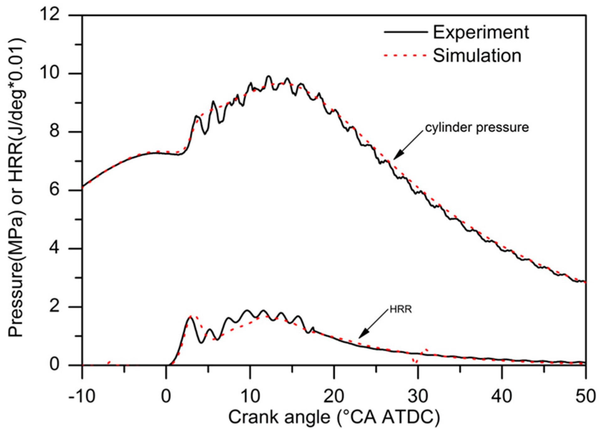
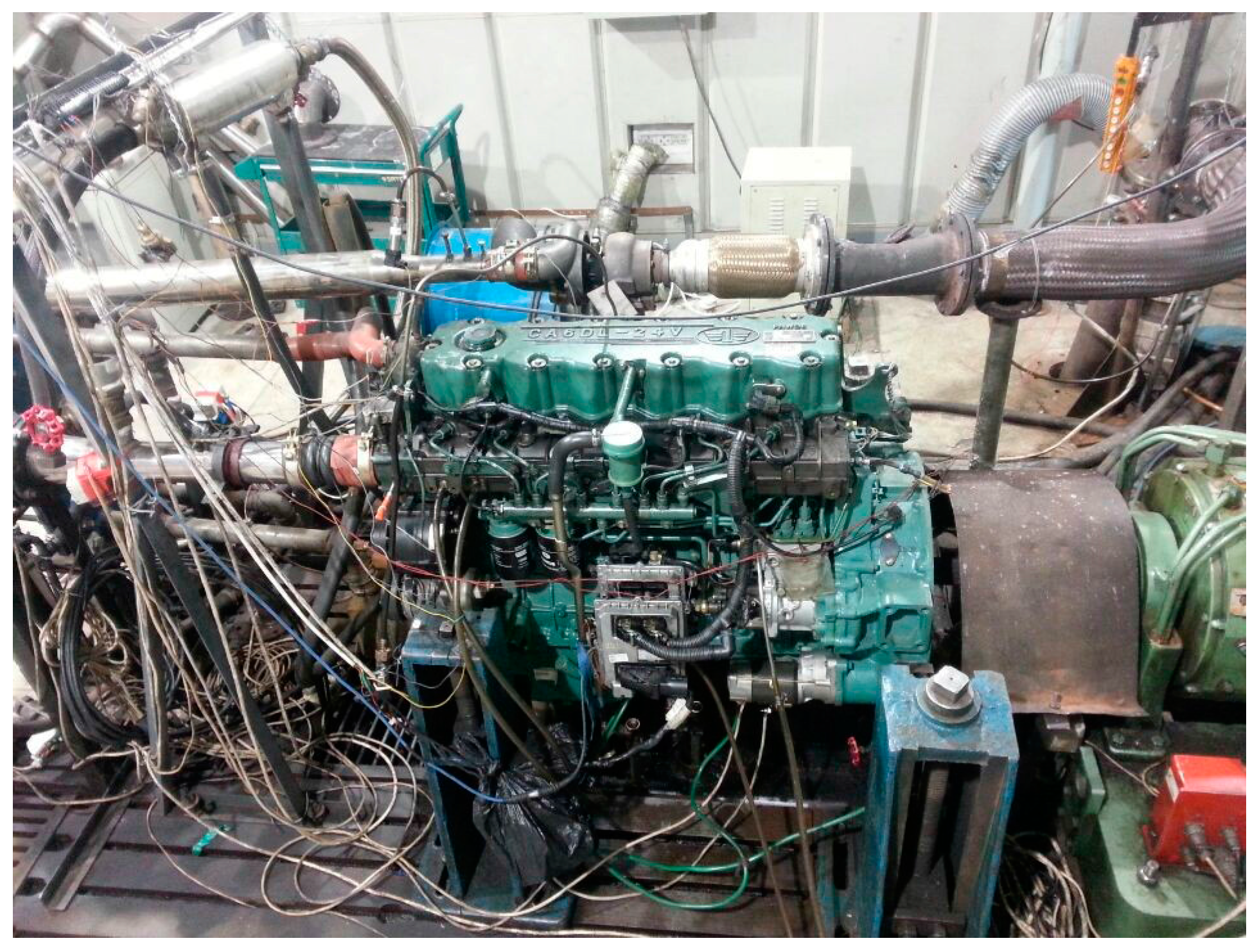
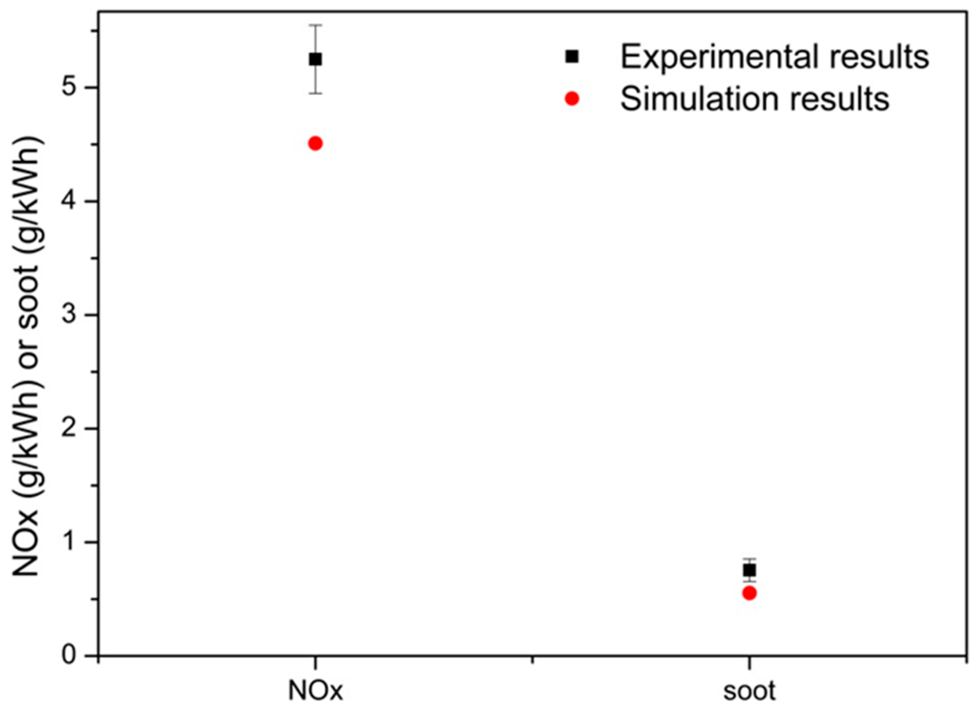
3. Validation of Simulation Model

The tested engine was a six-cylinder diesel engine with common rail injection system and intercooler as shown in Figure 3. The main specifications and operating conditions for simulation validation of the engine are shown in Table 2. Cylinder pressure was measured using Kistler 6025B piezoelectric pressure transducers (range 1–250 bar, accuracy of ±0.1%). Intake mass rate was measured by AVL1000 Transient Gas Mass Flow Meter (AVL 1000, AVL List GmbH, Graz, Austria).
Figure 4 shows comparisons of the cylinder pressure and heat release rate between the results of simulation and experiment. As shown in this figure, cylinder pressure and heat release rate of simulation results were in good agreement with that of the experiment. Only a small difference appears in the pressure curve and heat release rate curve during the initial combustion process.
Figure 5 shows comparisons of engine-out NOx and soot emissions between the results of simulation and experiment. It can be seen that predicted NOx and soot emissions were in good agreement with that of the experiment. The results indicate that the simulation models employed, such as combustion model, emission models, spray models and so on, are acceptable to predict diesel engine performance. Therefore, reasonable numerical models were employed in this study to predict combustion and emissions performance of EGR stratification based on the tested diesel engine.

4. Results and Discussion

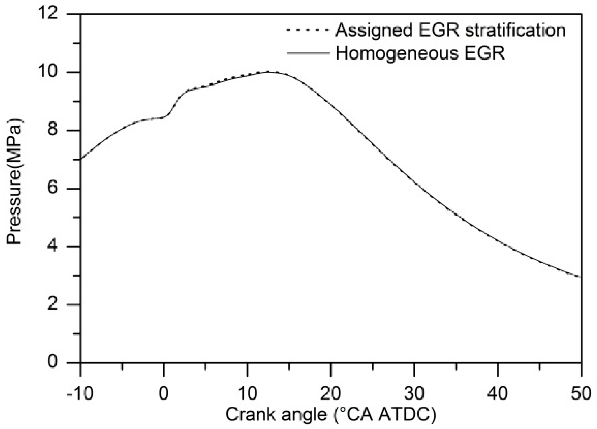
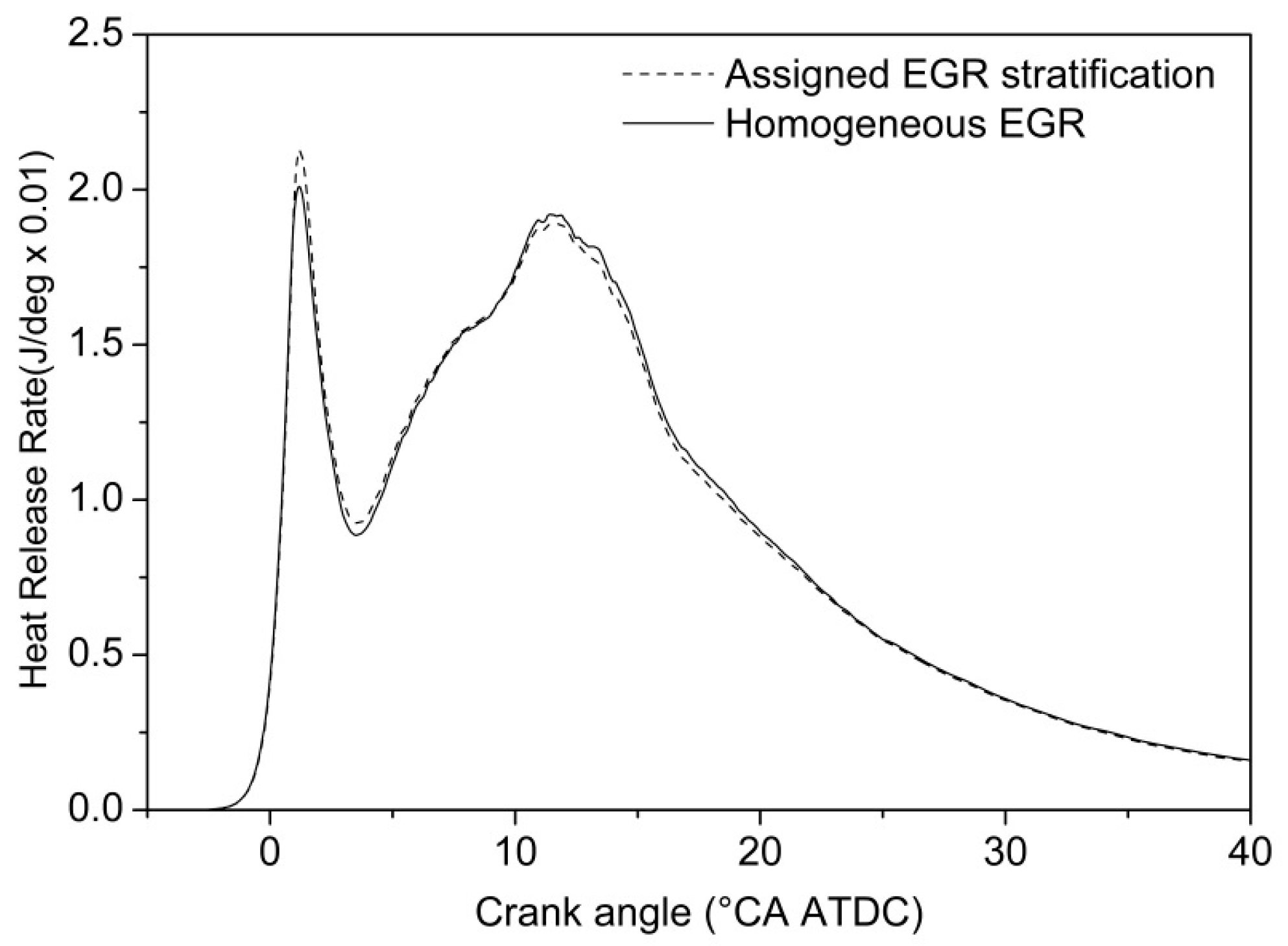
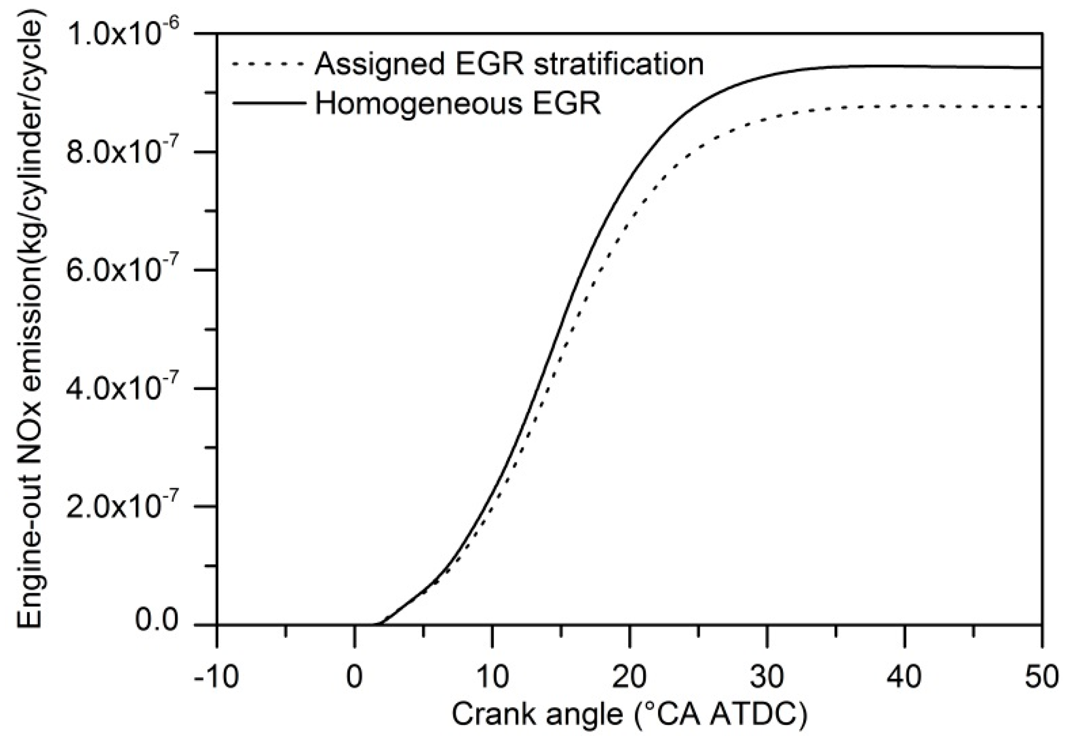
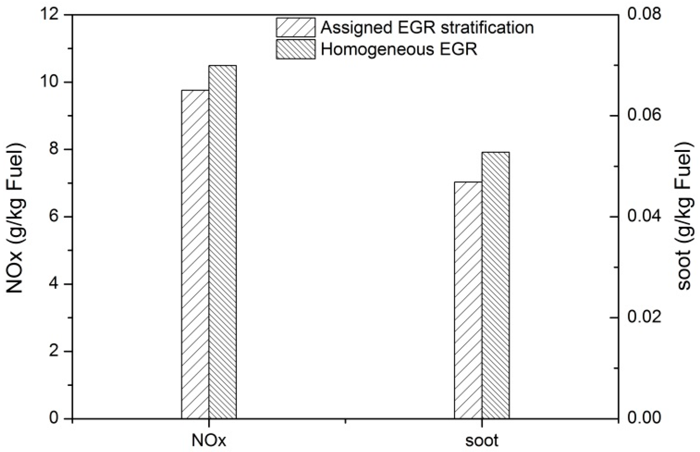
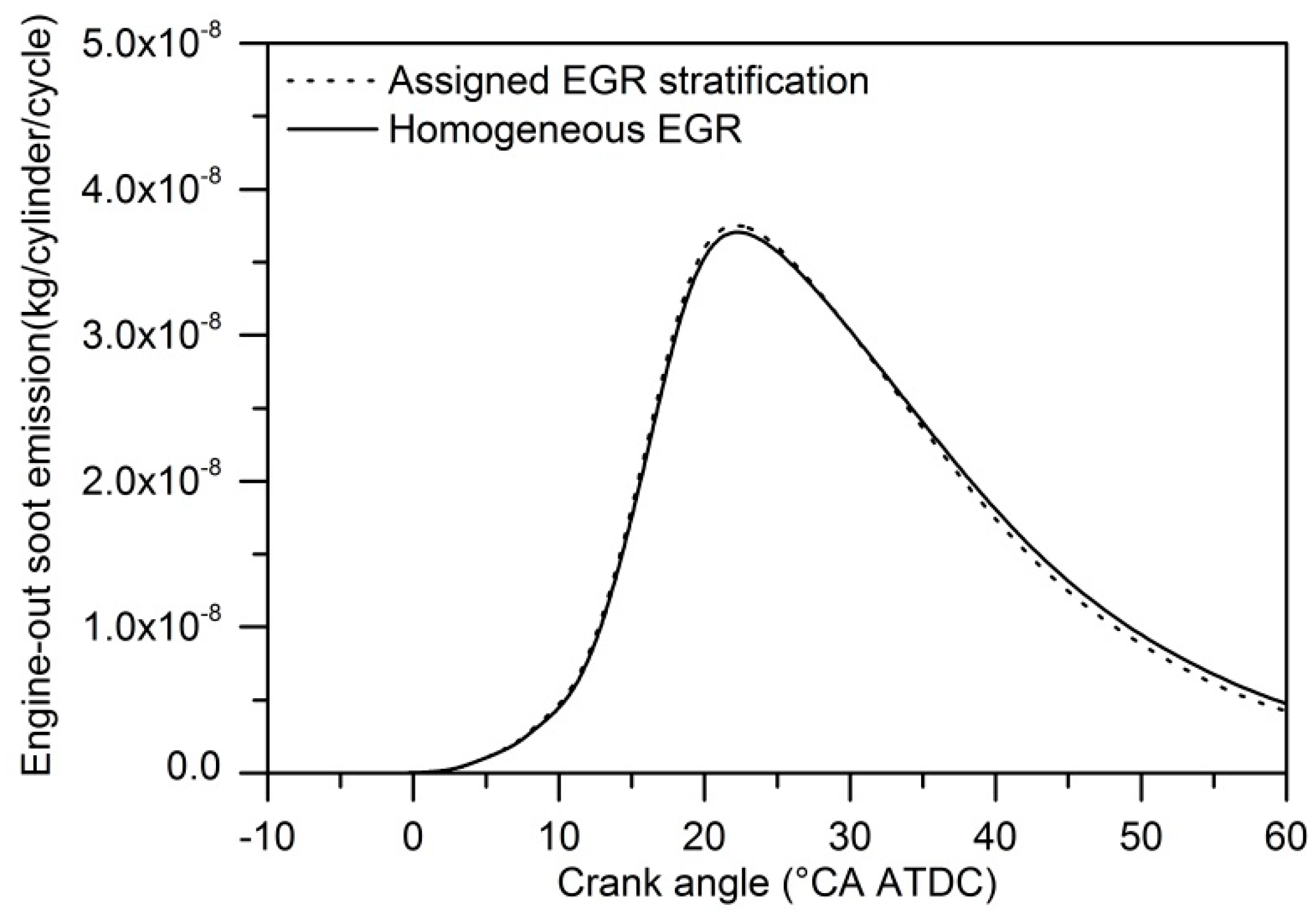
4.1. Comparisons between Uniform EGR and Assigned EGR Stratification

Figure 6 shows comparison of in-cylinder pressure between uniform EGR and assigned EGR stratification with equal mass of EGR in cylinder. It can be seen from the figure that there is little difference between the pressure curves of uniform EGR and assigned EGR stratification.
Figure 7 shows comparison of heat release rate between uniform EGR and assigned EGR. The peak value of heat release rate of assigned EGR stratification is higher than that of uniform EGR. The reason is that combustion of assigned EGR stratification is started from the region with higher EGR rate which lead to longer ignition delay and more fuel-air mixture at first combustion stage. EGR mass in cylinder between the two cases is equal, EGR rate is 20% of uniform EGR and local EGR rate is 30% of assigned EGR stratification. However, there is no obvious difference in pressure and heat release rate between the two different cases. It is the same oxygen mass and fuel mass that make little difference in cylinder pressure and heat release rate. The only difference between the two cases is the distribution of EGR.
Figure 8 shows comparison of specific emissions of engine-out NOx and soot between uniform EGR and assigned EGR stratification with equal mass of EGR in cylinder. It indicates that both specific engine-out NOx and soot emissions of assigned EGR stratification are lower than that of uniform EGR. The reduction of NOx and soot emissions is 7% and 11.2% respectively.
Figure 9 and Figure 10 show engine-out NOx and soot generation history of uniform EGR and assigned EGR stratification respectively. It can be seen in Figure 9 that NOx generated at same crank angle for the two cases, engine-out NOx of assigned EGR stratification is observed lower than that of uniform EGR owing to higher EGR rate at NOx generation region. Soot emissions generally increase with NOx reduction due to introduction of EGR, however, soot emissions decrease under the case of assigned EGR stratification. Figure 10 shows that the peak value of soot of assigned EGR stratification is higher than that of uniform EGR, while engine-out soot emissions is lower than that of uniform EGR. The reason is that under the case of assigned EGR stratification the growth of soot particles begins at a higher EGR region than for uniform EGR, but oxidation of soot particles is enhanced by a lower EGR region of assigned EGR stratification.

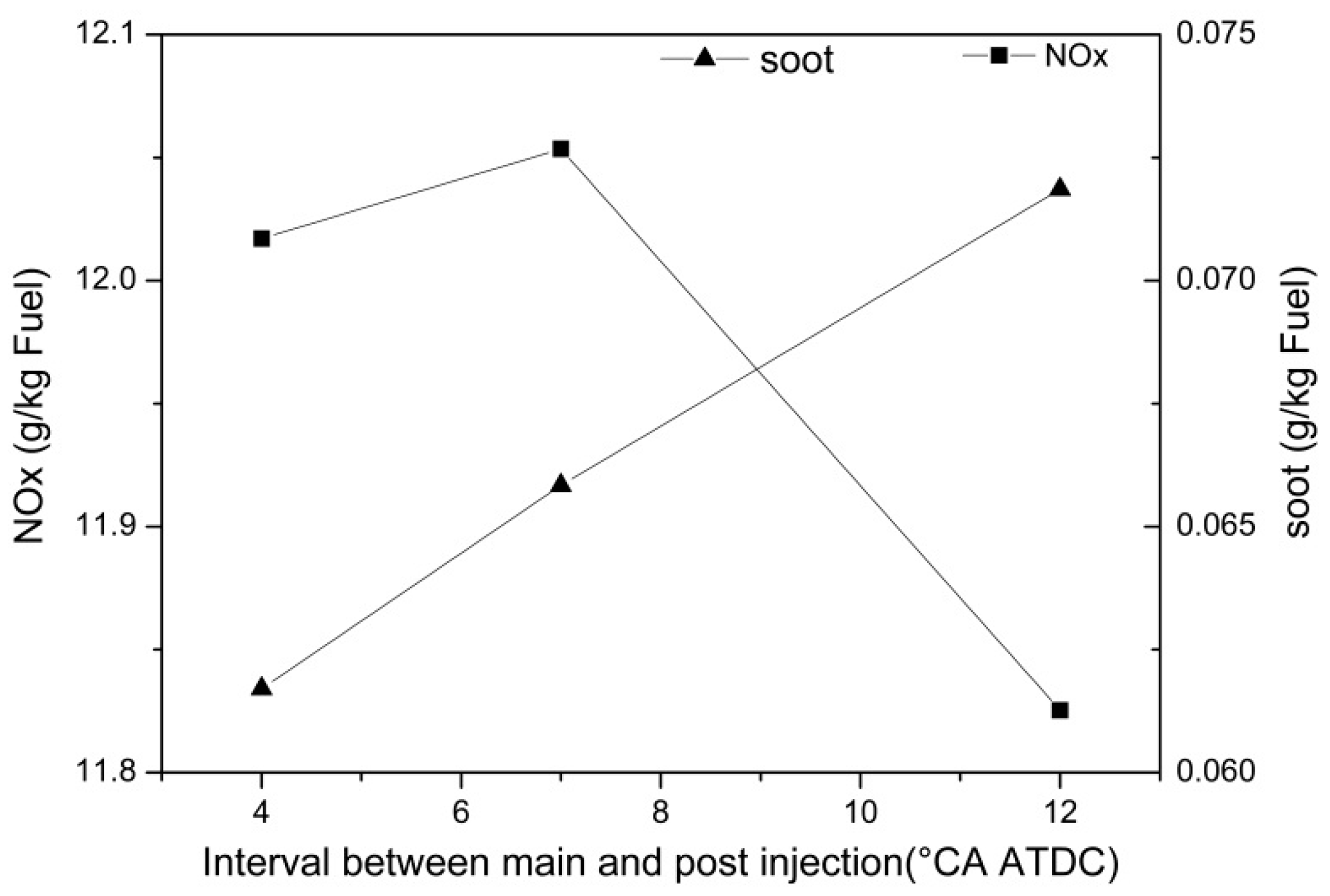
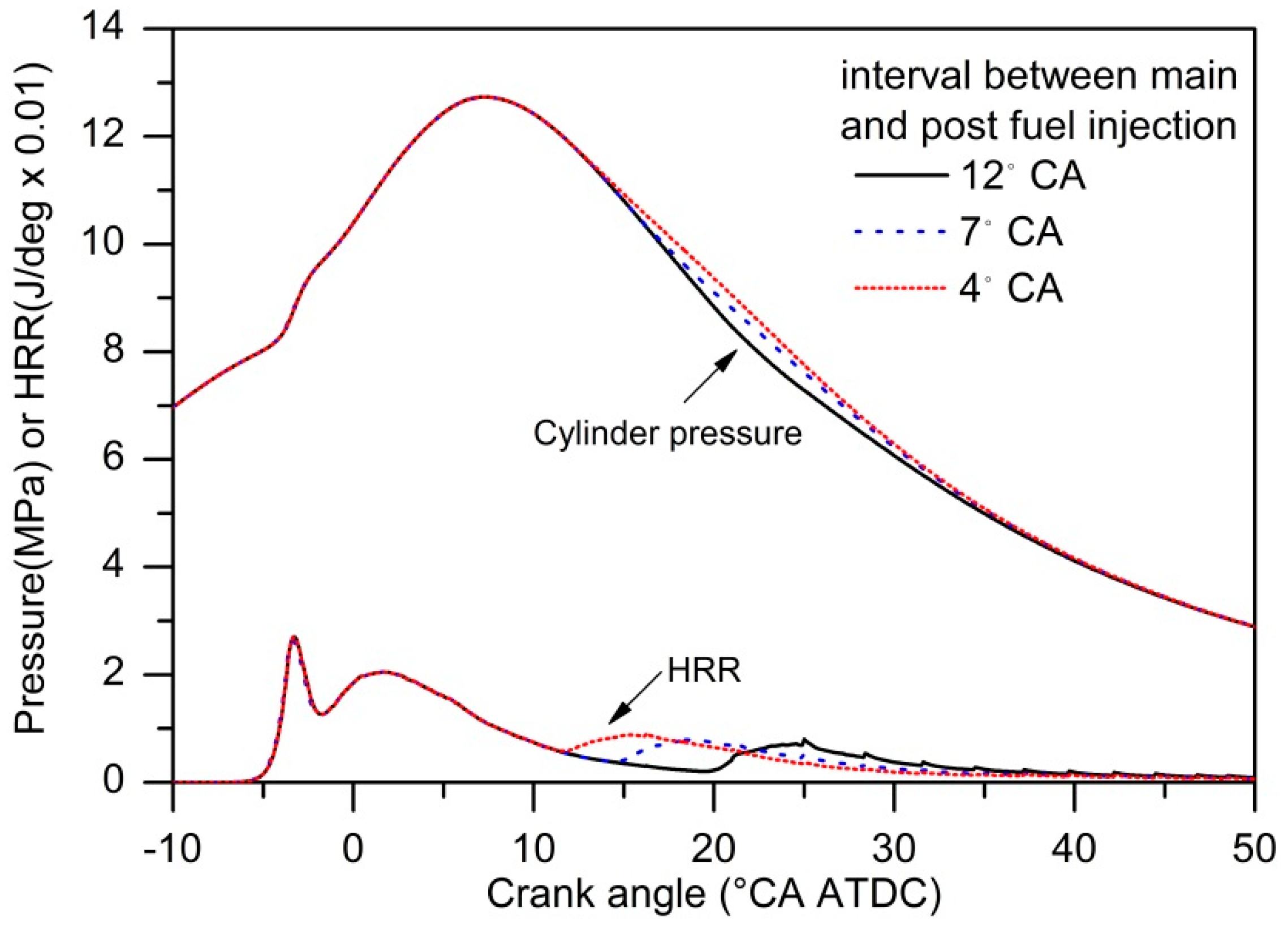
4.2. Effects of Interval of Main and Post Injection on Assigned EGR Stratification Combustion

Under the speed of 1650 r/min, fuel consumption is 24.76 kg/h, intake gas flow rate of 780 kg/h, local EGR rate 30%, and post injection fuel mass 20%. The effects of timing interval of main and post fuel injection on cylinder pressure and heat release rate and NOx and soot emissions were discussed.
Figure 11 shows comparisons of in-cylinder pressure and heat release rate versus crank angle with different interval crank angle between main and post injection under the condition of assigned EGR stratification. As shown in the figure, there is little difference of the peak values of in-cylinder pressure between the conditions with different interval angles. In-cylinder pressure of late phase of combustion decreases with the interval crank angle increase. For assigned EGR stratification combustion, later start of post fuel injection lowers the average combustion pressure and reduces the work per cycle transferred to the piston. Thus specific power is affected by interval time between main and post fuel injection. The heat release rate profiles for different interval of two-stage fuel injection were also shown in Figure 11. Different starts of post fuel injection produce different start of post combustion, so the second peak value of heat release rate decreases.
Lower average combustion pressure and a later heat release process change the generation of NOx and soot emissions, due to the longer interval between main and post fuel injection. Figure 12 shows specific engine-out NOx and soot emissions with different intervals between main and post fuel injection. It indicates that the trade-off between NOx and soot emissions still exists under the condition of assigned EGR stratification, however both NOx and soot emissions decreased when the interval between main and post fuel injection decreased from 7 to 4 °CA under which condition work per cycle transferred to the piston is higher. That means an optimal interval between main and post fuel injection exists for higher engine performance and lower toxic emissions.

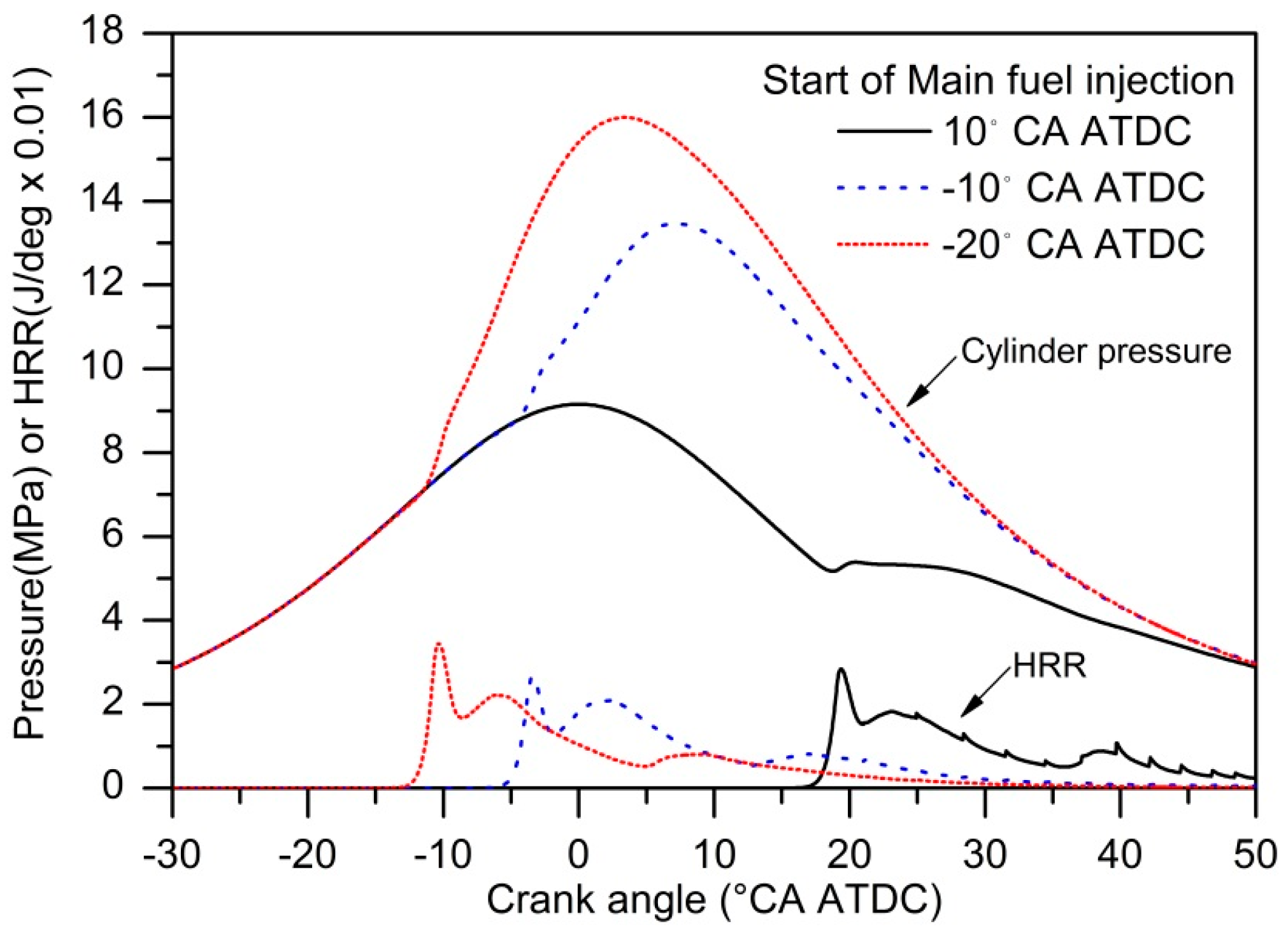
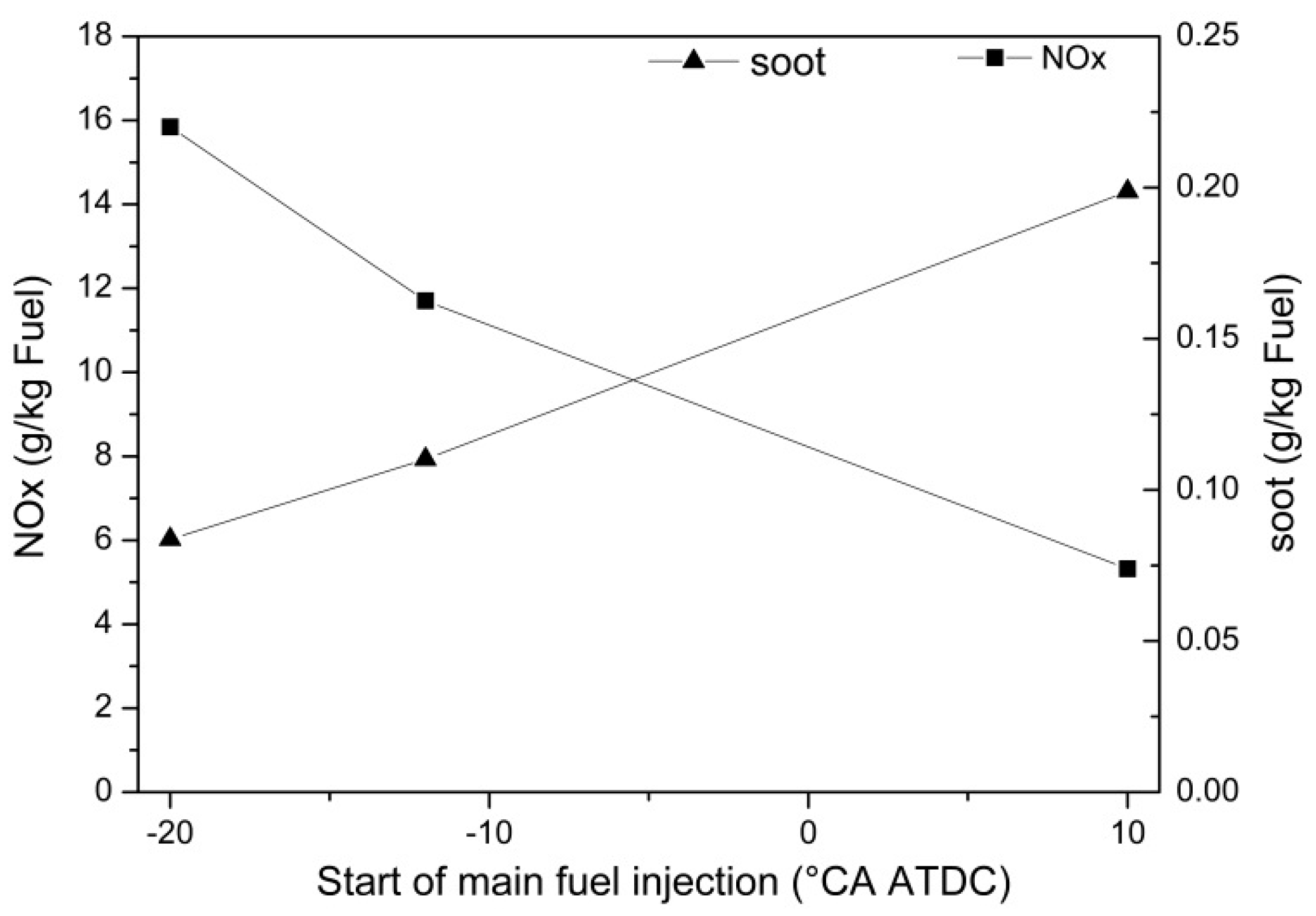
4.3. Effects of the Start of Main Injection of Two-Stage Fuel Injection on Assigned EGR Stratification Combustion

Figure 13 shows comparisons of in-cylinder pressure and heat release rate versus crank angle with different start timing of main fuel injection under the condition of assigned EGR stratification. As shown in the figure, there is obvious differences of the peak value of in-cylinder pressure with different main injection timing. For assigned EGR stratification combustion, later start of main injection lowers the peak value of combustion pressure and reduce the work per cycle transferred to the piston. The heat release rate profiles for different start of main injection of two-stage fuel injection were also shown in Figure 13. Different starts of main injection produce different start of fuel combustion, the peak value of heat release rate is higher at −20 °CA ATDC than the other two cases, and the peak value of heat release rate is the lowest at −10 °CA ATDC. Ignition delays increase as main fuel injection starts earlier, due to fuel injected to the engine cylinder with lower initial air temperature and pressure, which have great influence on in-cylinder pressure curve and heat release profile. The most favorable conditions for ignition lie in between represents the most optimal main injection timing for higher engine performance in power and heat release rate.
Figure 14 shows specific engine-out NOx and soot emissions with different starts of main fuel injection. In general, lower heat release rate reduce the formation of NOx emissions as main fuel injection timing delays and soot emissions increases for common diesel engine combustion. The same relationship between main injection timing and formation of NOx and soot emissions under the case of assigned EGR stratification as shown in Figure 14, however, with simultaneous lower engine-out NOx and soot emissions, proved in Figure 8. Different starts of main injection produce different performance of NOx and soot emissions. A deterioration of soot emissions was observed when the start of main fuel injection delayed, while NOx emissions reduced. The case with −10 °CA ATDC start of main fuel injection is suitable for acceptable NOx and soot emissions. That the most favorable conditions for emissions lie in between also represents the most optimal main injection timing for solving the efficiency-emissions trade-off.

5. Conclusions

EGR stratification combustion on diesel engines has been proposed and tried since 2010. Over the years, however, through the process of evolution and the increased understanding of the physical and chemical processes involved, only performance and emissions of diesel engines with EGR stratification achieved by supplying EGR asymmetrically were discussed in detail. Inhomogeneity of EGR distribution by supplying EGR asymmetrically is limited due to transient heavy turbulence in the engine cylinder. Therefore, assigned EGR stratification was employed to figure out the influences of significant EGR stratification on a diesel engine. The performance and emissions of diesel engines with assigned EGR stratification were compared with uniform EGR, and the effects of injection strategies on diesel with EGR stratification which was assigned manually in CFD codes were discussed in this paper. It proves that the simulation models employed are acceptable to predict diesel engine performance after model validation with a tested diesel engine.
The following conclusions were drawn:
(1)
Both specific engine-out NOx and soot emissions of assigned EGR stratification are lower than that of uniform EGR, with little penalty on cylinder pressure and heat release rate under the case that EGR mass in cylinder between uniform EGR and assigned EGR stratification is equal.
(2)
Both NOx and soot emissions decreased when the interval between main and post fuel injection decreased from 7 to 4 °CA, under which conditions work per cycle transferred to the piston is higher. The case with 4 °CA interval between main and post fuel injection is suitable for an acceptable efficiency-emissions trade-off.
(3)
The trade-off between NOx and soot still exists under the case of EGR stratification with different main fuel injection timing. A deterioration of soot emissions was observed when the start of the main fuel injection is delayed, while NOx emissions reduced. The case with −10 °CA ATDC start of main fuel injection is suitable for acceptable NOx and soot emissions.

Acknowledgments

The authors gratefully acknowledge the support of National Natural Science Foundation of China (51606052, 51506038), China Postdoctoral Science Foundation funded project (grant No. 2016T90284, 2015M571411), Weihai Science and Technical Plan Project (2016DXGJMS10, 2015DXGJMS013), projects WH20160104 and HIT(WH)201406 supported by the Scientific Research Foundation of the Harbin Institute of Technology at Weihai, and project HIT.NSRIF.2016095 supported by Natural Scientific Research Innovation Foundation at the Harbin Institute of Technology, Shandong Provincial Natural Science Foundation (ZR2015EQ003).

Author Contributions

Z.S. designed and performed the simulation, wrote the paper; W.C. installed and maitained the software Star-CD 4.22.018; X.J. helped to analysis the validation data; Z.L. conceived the simulation; S.W. contributed analysis methods; J.Y. provided the software.

Conflicts of Interest

The authors declare no conflict of interest.

References

  1. Mansor, M.R.A.; Abbood, M.M.; Mohamad, T.I. The influence of varying hydrogen-methane-diesel mixture ratio on the combustion characteristics and emissions of a direct injection diesel engine. Fuel 2017, 190, 281–291. [Google Scholar] [CrossRef]
  2. Peng, Z.J.; Liu, B.; Wang, W.J.; Lu, L.P. CFD Investigation into Diesel PCCI Combustion with Optimized Fuel Injection. Energies 2011, 4, 517–531. [Google Scholar] [CrossRef]
  3. Choi, W.; Choi, B.C. Estimation of the air entrainment characteristics of a transient high-pressure diesel spray. Proc. Inst. Mech. Eng. Part D J. Automob. Eng. 2005, 219, 1025–1036. [Google Scholar] [CrossRef]
  4. Jafarmadar, S.; Nemati, P. Analysis of Exhaust Gas Recirculation (EGR) effects on exergy terms in an engine operating with diesel oil and hydrogen. Energy 2017, 126, 746–755. [Google Scholar] [CrossRef]
  5. Han, D.; Duan, Y.Z.; Wang, C.H.; Lin, H.; Huang, Z.; Wooldridge, M.S. Experimental study of the two-stage injection process of fatty acid esters on a common rail injection system. Fuel 2016, 163, 214–222. [Google Scholar] [CrossRef]
  6. Shi, L.; Xiao, W.; Li, M.Y.; Lou, L.; Deng, K.Y. Research on the effects of injection strategy on LTC combustion based on two-stage fuel injection. Energy 2016, 121, 21–31. [Google Scholar] [CrossRef]
  7. Kim, G.; Moon, S.; Lee, S.; Min, K. Numerical Analysis of the Combustion and Emission Characteristics of Diesel Engines with Multiple Injection Strategies Using a Modified 2-D Flamelet Model. Energies 2017, 10, 1292. [Google Scholar] [CrossRef]
  8. Zamboni, G.; Moggia, S.; Capobianco, M. Effects of a Dual-Loop Exhaust Gas Recirculation System and Variable Nozzle Turbine Control on the Operating Parameters of an Automotive Diesel Engine. Energies 2017, 10, 47. [Google Scholar] [CrossRef]
  9. Ge, J.C.; Kim, M.S.; Yoon, S.K.; Choi, N.J. Effects of Pilot Injection Timing and EGR on Combustion, Performance and Exhaust Emissions in a Common Rail Diesel Engine Fueled with a Canola Oil Biodiesel-Diesel Blend. Energies 2015, 8, 7312–7325. [Google Scholar] [CrossRef]
  10. Khandal, S.V.; Banapurmath, N.R.; Gaitonde, V.N.; Hiremath, S.S. Paradigm shift from mechanical direct injection diesel engines to advanced injection strategies of diesel homogeneous charge compression ignition (HCCI) engines- A comprehensive review. Renew. Sustain. Energy Rev. 2017, 70, 369–384. [Google Scholar] [CrossRef]
  11. Kim, M.Y.; Lee, C.S. Effect of a narrow fuel spray angle and a dual injection configuration on the improvement of exhaust emissions in a HCCI diesel engine. Fuel 2007, 86, 2871–2880. [Google Scholar] [CrossRef]
  12. Krishnan, S.R.; Srinivasan, K.K.; Raihan, M.S. The effect of injection parameters and boost pressure on diesel-propane dual fuel low temperature combustion in a single-cylinder research engine. Fuel 2016, 184, 490–502. [Google Scholar] [CrossRef]
  13. Zhang, J.; Jing, W.; Roberts, W.L.; Fang, T.G. Soot measurements for diesel and biodiesel spray combustion under high temperature highly diluted ambient conditions. Fuel 2014, 135, 340–351. [Google Scholar] [CrossRef]
  14. Dowell, P.G.; Akehurst, S.; Burke, R.D. A real-time capable mixing controlled combustion model for highly diluted conditions. Energy 2017, 133, 1035–1049. [Google Scholar] [CrossRef]
  15. Feng, L.Y.; Tian, J.P.; Long, W.Q.; Gong, W.X.; Du, B.G.; Li, D.; Chen, L. Decreasing NOx of a Low-Speed Two-Stroke Marine Diesel Engine by Using In-Cylinder Emission Control Measures. Energies 2016, 9, 304. [Google Scholar] [CrossRef]
  16. Lawler, B.; Hoffman, M.; Filipi, Z.; Guralp, O.; Najt, P. Development of a Postprocessing Methodology for Studying Thermal Stratification in an HCCI Engine. J. Eng. Gas Turbines Power 2012, 134. [Google Scholar] [CrossRef]
  17. Reader, G.T.; Asad, U.; Zheng, M. Energy efficiency trade-off with phasing of HCCI combustion. Int. J. Engine Res. 2013, 37, 200–210. [Google Scholar] [CrossRef]
  18. Ramesh, N.; Mallikarjuna, J.M. Low temperature combustion strategy in an off-highway diesel engine—Experimental and CFD study. Appl. Therm. Eng. 2017, 124, 844–854. [Google Scholar] [CrossRef]
  19. Kim, D.S.; Lee, C.S. Improved emission characteristics of HCCI engine by various premixed fuels and cooled EGR. Fuel 2006, 85, 695–704. [Google Scholar] [CrossRef]
  20. Yoshimura, K.; Mori, S.; Nakama, K.; Kusaka, J. Studies on the Effect of In-Cylinder Charge Stratifications on High Load HCCI Combustion. SAE Int. J. Engines 2016, 9, 2337–2349. [Google Scholar] [CrossRef]
  21. Zheng, Z.L.; Yao, M.F. Charge stratification to control HCCI: Experiments and CFD modeling with n-heptane as fuel. Fuel 2009, 88, 354–365. [Google Scholar] [CrossRef]
  22. Shen, Z.J.; Liu, Z.C.; Tian, T.; Li, K.; Liu, J.W. Simulation of EGR stratification on timing-sequential regionalized diesel combustion. In Proceedings of the FISITA 2012 World Automotive Congress; Springer-Verlag: Berlin/Heidelberg, Germany, 2012; Volume 190, pp. 827–838. [Google Scholar]
  23. Flynn, P.F.; Durrett, R.P.; Hunter, G.L.; Loye, A.O.; Akinyemi, O.C.; Dec, J.E.; Westbrook, C.K. Diesel Combustion: An Integrated View Combining Laser Diagnostics, Chemical Kinetics, and Empirical Validation; SAE Technical Paper; SAE International: Warrendale, PA, USA, 1999. [Google Scholar]
  24. Kamimoto, T.; Bae, M.H. High Combustion Temperature for the Reduction of Particulate in Diesel Engines; SAE Technical Paper 880423; SAE International: Warrendale, PA, USA, 1988. [Google Scholar]
  25. Akihama, K.; Takatori, Y.; Inagaki, K.; Sasaki, S.; Dean, A.M. Mechanism of the Smokeless Rich Diesel Combustion by Reducing Temperature; SAE International: Warrendale, PA, USA, 2011. [Google Scholar]
  26. Xiong, Q.; Inaba, K.; Li, T.; Shibata, G.; Ogawa, H. Influence of fuel properties on operational range and combustion characteristics of premixed diesel combustion with high volatility fuel. Int. J. Engine Res. 2014, 15, 557–564. [Google Scholar] [CrossRef]
  27. Esangbedo, C.; Boehman, A.L.; Perez, J.M. Characteristics of diesel engine soot that lead to excessive oil thickening. Tribol. Int. 2012, 47, 194–203. [Google Scholar] [CrossRef]
  28. Rothamer, D.A.; Snyder, J.A.; Hanson, R.K.; Steeper, R.R.; Fitzgerald, R.P. Simultaneous imaging of exhaust gas residuals and temperature during HCCI combustion. Proc. Combust. Inst. 2009, 32, 2869–2876. [Google Scholar] [CrossRef]
  29. Choi, S.; Park, W.; Lee, S.; Min, K.; Choi, H. Methods for in-cylinder EGR stratification and its effects on combustion and emission characteristics in a diesel engine. Energy 2011, 36, 6948–6959. [Google Scholar] [CrossRef]
  30. Fuyuto, T.; Nagata, M.; Hotta, Y.; Inagaki, K.; Nakakita, K.; Sakata, I. In-cylinder stratification of external exhaust gas recirculation for controlling diesel combustion. Int. J. Engine Res. 2010, 11, 1–15. [Google Scholar] [CrossRef]
  31. Andre, M.; Walter, B.; Bruneaux, G.; Foucher, F.; Mounaım-Rousselle, C. Exhaust gas recirculation stratification to control diesel homogeneous charge compression ignition combustion. Int. J. Engine Res. 2012, 13, 429–447. [Google Scholar] [CrossRef]
  32. Shen, Z.; Liu, Z.; Tian, J.; Liu, J. Investigation of the in-cylinder gas stratification of diesel engine during intake and compression stroke. Energy 2014, 72, 671–679. [Google Scholar] [CrossRef]
  33. Lee, J.; Chu, S.; Cha, J.; Choi, H.; Min, K. Effect of the diesel injection strategy on the combustion and emissions of propane/diesel dual fuel premixed charge compression ignition engines. Energy 2015, 93, 1041–1052. [Google Scholar] [CrossRef]
  34. Fang, T.; Lee, C.F.F. Low sooting combustion of narrow-angle wall-guided sprays in an HSDI diesel engine with retarded injection timings. Fuel 2011, 90, 1449–1456. [Google Scholar] [CrossRef]
  35. Zhang, C.; Zhang, C.H.; Xue, L.; Li, Y.Y. Combustion characteristics and operation range of a RCCI combustion engine fueled with direct injection n-heptane and pipe injection n-butanol. Energy 2017, 125, 439–448. [Google Scholar] [CrossRef]
  36. Chen, G.S.; Di, L.; Shen, Y.G.; Zhang, W.; Mao, B. Strategies for emissions control in heavy-duty diesel engines to achieve low-emissions combustion with a high efficiency. Proc. Inst. Mech. Eng. Part D J. Automob. Eng. 2016, 230, 593–608. [Google Scholar] [CrossRef]
  37. Han, Z.; Reitz, R.D. Turbulence modeling of internal combustion engines using RNG k-ε models. Combust. Sci. Technol. 1995, 106, 267–295. [Google Scholar] [CrossRef]
  38. USER GUIDE. STAR-CD, version 4.28; CD-adapco: London, UK, 2017.
Figure 1. Simulation model of six-cylinder diesel engine, (a) O-grid combustion chamber; (b) simulation model at top dead center (TDC); (c) simulation model at bottom dead center (BDC).
Energies 11 00515 g001
Figure 2. The distribution of CO2 mass fraction of EGR stratification assigned radically at −30 °CA ATDC.
Energies 11 00515 g002
Figure 3. The test bench.
Energies 11 00515 g003
Figure 4. Comparison of in-cylinder pressure and heat release rate versus crank angle between simulation and experiment results.
Energies 11 00515 g004
Figure 5. Comparison of engine out NOx and soot emission between simulation and experiment results.
Energies 11 00515 g005
Figure 6. Comparison of in-cylinder pressure between uniform EGR and assigned EGR stratification with equal mass of EGR in cylinder.
Energies 11 00515 g006
Figure 7. Comparison of heat release rate between uniform EGR and assigned EGR stratification with equal mass of EGR in cylinder.
Energies 11 00515 g007
Figure 8. Comparison of engine-out NOx and soot between uniform EGR and assigned EGR stratification with equal mass of EGR in cylinder.
Energies 11 00515 g008
Figure 9. Comparison of engine-out NOx history between uniform EGR and assigned EGR stratification with equal mass of EGR in cylinder.
Energies 11 00515 g009
Figure 10. Comparison of engine-out soot history between uniform EGR and assigned EGR stratification with equal mass of EGR in cylinder.
Energies 11 00515 g010
Figure 11. Comparisons of in-cylinder pressure and heat release rate versus crank angle under the cases of assigned EGR stratification with different interval crank angle between main and post injection.
Energies 11 00515 g011
Figure 12. Comparisons of NOx and soot emissions under the cases of assigned EGR stratification with different interval crank angle between main and post injection.
Energies 11 00515 g012
Figure 13. Comparisons of in-cylinder pressure and heat release rate versus crank angle under the cases of assigned EGR stratification with different start time of main fuel injection.
Energies 11 00515 g013
Figure 14. Comparisons of NOx and soot emissions under the cases of assigned EGR stratification with different start time of main fuel injection.
Energies 11 00515 g014
Table 1. Simulation conditions of exhaust gas recirculation (EGR) stratification combustion.
CasesConditionsSOI 1Interval 2
°CA ATDC°CA
11650 r/min 3−8Single 4
21650 r/min, assigned EGR stratification in cylinder with local EGR rate is 30%−8Single 4
3−205.5
4−105.5
5105.5
6−124
7−127
8−1212
1 SOI, start of main fuel injection; 2 Interval between main fuel injection and post fuel injection; 3 1650 r/min, calculated from European Steady-state Condition, 50% load, Uniform distribution of EGR in cylinder; 4 Single, single fuel injection.
Table 2. Engine specifications and operating condition for simulation validation.
Engine TypeIn-Line 6 Cylinder DI Diesel Engine
valves4
Piston bowlω
superchargeTurbocharging
EGR coolingIntercooling
Bore × Stroke (mm × mm)112 × 145
Displacement (L)8.6
Compression Ratio17.0:1
Rated Power/Speed (kW/rpm)257/2100
Intake air temperature (K)313
EGR rate10.6
Fuel injection pressure (MPa)120
SOI (°CA ATDC)−8
Injection typeSingle injection
Fuel consumption (kg/h)24.23
Intake mass flow rate (kg/h)649.47

