Article

A Study on Electrofuels in Aviation

1
Institute of Technical Combustion, Leibniz Universität Hannover, Welfengarten 1A, 30167 Hannover, Germany
2
Institute of Environmental and Sustainable Chemistry, TU-Braunschweig, Hagenring 30, 38106 Braunschweig, Germany
3
Institute of Turbomachinery and Fluid Dynamics, Leibniz Universität Hannover, Appelstraße 9, 30167 Hannover, Germany
4
Institute of Jet propulsion and Turbomachinery, TU-Braunschweig, Hermann-Blenk-Strasse 37, 38108 Braunschweig, Germany
*
Author to whom correspondence should be addressed.
Energies 2018, 11(2), 392; https://doi.org/10.3390/en11020392
Submission received: 21 December 2017 / Revised: 18 January 2018 / Accepted: 31 January 2018 / Published: 8 February 2018
(This article belongs to the Special Issue Towards a Transformation to Sustainable Aviation Systems)

Abstract

:
With the growth of aviation traffic and the demand for emission reduction, alternative fuels like the so-called electrofuels could comprise a sustainable solution. Electrofuels are understood as those that use renewable energy for fuel synthesis and that are carbon-neutral with respect to greenhouse gas emission. In this study, five potential electrofuels are discussed with respect to the potential application as aviation fuels, being n-octane, methanol, methane, hydrogen and ammonia, and compared to conventional Jet A-1 fuel. Three important aspects are illuminated. Firstly, the synthesis process of the electrofuel is described with its technological paths, its energy efficiency and the maturity or research need of the production. Secondly, the physico-chemical properties are compared with respect to specific energy, energy density, as well as those properties relevant to the combustion of the fuels, i.e., autoignition delay time, adiabatic flame temperature, laminar flame speed and extinction strain rate. Results show that the physical and combustion properties significantly differ from jet fuel, except for n-octane. The results describe how the different electrofuels perform with respect to important aspects such as fuel and air mass flow rates. In addition, the results help determine mixture properties of the exhaust gas for each electrofuel. Thirdly, a turbine configuration is investigated at a constant operating point to further analyze the drop-in potential of electrofuels in aircraft engines. It is found that electrofuels can generally substitute conventional kerosene-based fuels, but have some downsides in the form of higher structural loads and potentially lower efficiencies. Finally, a preliminary comparative evaluation matrix is developed. It contains specifically those fields for the different proposed electrofuels where special challenges and problematic points are seen that need more research for potential application. Synthetically-produced n-octane is seen as a potential candidate for a future electrofuel where even a drop-in capability is given. For the other fuels, more issues need further research to allow the application as electrofuels in aviation. Specifically interesting could be the combination of hydrogen with ammonia in the far future; however, the research is just at the beginning stage.

1. Introduction

The vision of fully-sustainable aviation demands energy sources to be based on renewable energies and their utilization without any environmental foot-print. The latter means that neither greenhouse gas, nor local pollutants should be emitted. At first glance, electrically-based aviation could be an option; however, the energy storage capacity for direct electrical energy in battery packs is severely limited. An alternative option for aviation might be based on the utilization of so-called electrofuels [1]. Here, the fuel can be seen primarily as an energy carrier in the sense that on the ground, the electrical energy is “stored” in the fuel with a high energy capacity by producing the fuel synthetically with the help of electricity. This fuel then is transported within the airplane and is used there for the energy supply necessary for flying, for example with the help of combustion processes. Assuming the ground-based “storage process” of energy in the fuel to have no emission of greenhouse gases (essentially CO2) or other emissions, which, at least ideally, might be possible by the use of renewable power sources like wind- or solar-based electricity, such electrofuels could be seen as CO2-neutral. This is evident for such energy-carrying fuels without carbon content (e.g., H2 or NH3), but is valid (at least ideally) even for electrofuels based on the hydro-carbon structure. For the former group, no direct CO2 will be emitted with combustion in-flight, while the latter will have such emissions, but as the carbon is taken out of the atmosphere during the production process of this fuel, it still can be seen as CO2-neutral. Burning of electrofuels alone does not prevent other combustion emissions, like soot particles, nitrogen-oxides (NOx), carbon-monoxide (CO) or unburnt hydro-carbon (CxHy). However, as such electrofuels will be produced synthetically, the design and selection of these fuels may allow new degrees of freedom in such a way that also the local combustion emissions might be reduced significantly. One example could be that the fuel would allow lean premixed combustion instead of non-premixed combustion in current air-engines, operating with a high excess air-to-fuel ratio (lean combustion). With lean premixed combustion, any soot-particle emission is prevented, and the NOx-emission is reduced by an order of magnitude [2]. However, here, special attention is needed to prevent pre-ignition or flashback of the flame into the mixing zone. The current study will not focus on this aspect, as the two steps towards fully-renewable and fully-CO2-free aviation alone are already extremely challenging.
If fuels were to be produced from green electricity, but would have rather similar properties as the current aviation fuels (for example, Jet A, Jet A-1, JP-8), these fuels could be described as “drop-in fuels”. They can be used within the existing aviation engines, maybe with a few modifications to adapt them to the slightly different properties. The option to use “drop-in” fuels is commonly seen as the first possible step on the path toward electro-based sustainable aviation. An overview of the recent development of conventional drop-in fuels can be found in [3]. If radically different fuels were to be used, also the combustion engines would need to be redesigned. This would require an extensive effort on the side of air-engine development, as several issues have to be addressed besides the aero-thermo-chemical properties. However, this gives many more degrees of freedom for new combustion concepts and even new engine architectures.
The use of alternative fuels in aviation has some historic background. Already in the 1960s, some activities had been studied on the basis of the utilization of ammonia (NH3) as the fuel, for instance in gas turbine combustion by Newhall and Starkman [4], Pratt [5] and Verkamp et al. [6]. The basic results were that ammonia combustion is possible, but has the downside of a limited ignition range and suffers from limited flame stability. One option would be to burn ammonia with oxygen. Here, based on rocket engine concepts, a military hypersonic research aircraft, X-15, was powered by a rocket-engine using anhydrous ammonia and liquid oxygen as fuel in the 1950s [7]. However, this option seems to be beyond the scope of applicability for general aviation purpose. Other options are to mix NH3 with other more reactive fuels. This was more recently studied specifically in a micro-gas turbine with fuel mixtures of NH3/kerosene and NH3/CH4 [8,9].
Furthermore, the utilization of hydrogen as aviation fuel has been studied for decades. In the 1970s, Brewer [10,11] discussed the usage of liquid hydrogen fuel in aviation, followed by others [12]: for high-speed air transportation [13,14,15], including questions of airport safety, and [16]. The proof of concept to use hydrogen in aviation was conducted by the first experimental cryogenic aircraft, Tupolev Tu-155 [17] in the 1980s, which was powered by liquefied hydrogen and natural gas. In [18], a comparison of hydrogen with hydrocarbon fuels for aviation is discussed. Further discussion of hydrogen utilization for aircraft engines is given for instance in [19,20,21,22,23,24,25,26,27]. A good review with respect to hydrogen in aviation is given specifically by Cecere et al. [28].
Comparative studies for different fuels are given, for instance, by Sehra et al. [29] and Edwards et al. [30]. A very recent review on sustainable alternative aviation fuels can be found in Yilmaz et al. [31] (2017). Life cycle analysis comparing different fuels has been performed, for instance, by Pereira et al. [25] (2014), comparing specifically liquid hydrogen and liquid natural gas, and Bicer et al. [32] (2017), comparing hydrogen, ammonia, methanol, ethanol and liquefied natural gas for aircraft. The last work concludes that specifically, ammonia- and hydrogen-fueled aircraft can potentially decrease the overall environmental impact.
The aim of this study is to compare different fuels that may have the potential for utilization as electrofuels in aviation in a first-order approximation regarding their synthesis, combustion properties and their impact on the aircraft engine, i.e., combustion chamber and turbine. The study will focus on the basic aero-thermo-chemical issues and will only rarely mention several other aspects like constructional constraints, safety, production aspects and costs.
The remainder of this paper begins with a definition of electrofuels, and the synthesis process of five potential electrofuels: n-octane, methanol, methane, hydrogen and ammonia. Then, the characteristic combustion properties of five selected electrofuels are compared with those of conventional jet fuel. For the comparison, the autoignition delay time, adiabatic flame temperature, laminar flame speed and extinction strain rate are calculated numerically and analyzed. Thirdly, turbine performance characteristics are investigated with a thermodynamic analysis and with the help of three-dimensional numerical simulation of a turbine to compare the selected electrofuels. In a comparative discussion, the major results are collected in the form of an assessment matrix, including the potential advantages and disadvantages, marking also those points that are not yet sufficiently well known for analysis.
In that sense, this study can be seen to be at a rather initial level of scientific discussion. Both the limited fuel resources, as well as that of the environmental impact of energy utilization, here, in aviation, are questions that have been gaining more and more importance among human beings within the limited environment of the Earth.

2. Synthesis of Electrofuels

2.1. Electrofuels

In the framework of the ongoing Energiewende, i.e., the transition from fossil energy resources towards renewable energies, electric energy is assumed to become central in future sustainable transportation, including aviation. A key challenge in using electric energy for transportation (and for aviation in particular) is the limited on-board energy storage capacity in batteries. Even with expected improvements, the physical boundaries of batteries will not allow the energy density to reach that of chemical fuels. An alternative path is the storage of electric energy within the molecular structure of gaseous or liquid fuels via electrolysis/electrosynthesis. The concept behind this approach is generally referred to as “power-to-gas” or “power-to-liquid”, with suitable fuels often being denominated as “electrofuels”. A definition of electrofuels is proposed here:
  • Electrofuels are a class of carbon-neutral fuels that are made by storing electrical energy from renewable sources in the chemical bonds of liquid or gaseous fuels.
With this definition, the following properties are characteristic:
  • Electrofuels are understood to be carbon-neutral, assuming that the electrical energy for production is carbon-neutral and is coming from renewable sources such as wind power or photovoltaics. This definition allows comparing the utilization of electrofuels fully with direct electrical mobility.
  • The energy density of electrofuels is typically much higher than that of batteries. The aspect of “energy storage” is central to electrofuels.
  • It is assumed that the electrofuel is either free of carbon (like H2 or NH3) or contains carbon taken from the atmosphere within recent years, to be carbon-neutral. Thus electrofuels may be based on carbon-containing biofuels as feedstock.
  • Electrofuels are utilized either similarly to conventional fuels with combustion or are transformed back to electricity directly in fuel cells.
As the electrofuels can be seen as energy storage, a decoupling between the time and location of production and of utilization is possible, which is an important characteristic property of electrofuels with respect to the fluctuating availability of wind power and photovoltaics. Additionally, electrofuels can have good storage and transportability properties, being important for use in aviation. The current study focuses on the utilization of electrofuels with combustion, leaving out the fuel cell approach.

2.2. Hydrogen from Water Electrolysis

The electrolysis of water to produce hydrogen has been well known since the end of the 18th Century [33]. The energy efficiency of the water electrolysis is already high (70–80% [34]). However, so far, steam reforming of fossil substances is still the dominant production process because of the low gas prices compared to electricity [35]. Hydrogen is an almost ideal electrofuel and was, for a long time, considered as the core energy carrier of future energy systems (see, e.g., [36]). Hydrogen possesses the highest gravimetric energy density of all fuels. However, hydrogen has a very low volumetric energy density and a high diffusion coefficient, which makes hydrogen difficult to store [37]. Compression and liquefaction are the main ways to store hydrogen effectively, but hydrogen compression consumes 15.5% of the hydrogen’s inner energy content and liquefaction up to 45% [37]. The use of hydrogen in a combustion engine or its oxidation in a fuel cell (“cold combustion”) currently yields efficiencies from 40% (combustion) up to 55% (fuel cell). Well-to-wheel efficiency would be, given the data above, between 15.4 and 37.2%.

2.3. Power-To-X

Due to the obstacles in using hydrogen as a fuel, molecular hydrogen is generally rather used as a chemical intermediate for the production of easily manageable liquid or gaseous fuels, such as methane (“power-to-gas”) and longer chained hydrocarbons (“power-to-liquid”) from carbon dioxide, or for the production of ammonia from nitrogen (“power-to-ammonia”). All these compounds can be fundamentally understood as molecular hydrogen carriers.
All three conventional “power-to-X” technologies, depicted in Figure 1A–C, share the combination of the electrolytic hydrogen synthesis and a subsequent catalytic conversion of the hydrogen gas with carbon dioxide or nitrogen. Based on the chemical stability of the carbon dioxide and the dinitrogen molecules and the resulting high activation barrier of these reactions, the respective catalytic conversions generally require comparatively drastic pressure and temperature conditions. The power-to-gas process (Figure 1A) usually involves the methanation of hydrogen and carbon dioxide, e.g., by the exothermic Sabatier process: CO2 + 4H2 → CH4 + 2 H2O. Methane is much easier to transport and to store than hydrogen. Based on its availability from fossil resources (natural gas), methane is already a well-established fuel for ground transportation. Infrastructure and motor optimizations are at a high level compared to other novel fuels, which represents a major advantage. Methane can be used either as compressed gas (compression of 200–250 bar) or in liquefied form (boiling point of −161.5 °C). The synthesis of longer chained hydrocarbons is achieved via the power-to-liquid process (Figure 1B). In the first step, a fraction of the electrolytic hydrogen is required to reduce carbon dioxide to carbon monoxide. Mixed with further hydrogen, the latter forms syngas: the precursor for the subsequent Fischer–Tropsch synthesis. Depending on the operational conditions such as syngas composition, pressure and temperature, as well as the catalyst system, fuels with desired properties can be synthesized. From a fuel perspective, the power-to-ammonia (Figure 1C) approach provides the opportunity for a completely carbon-free fuel and for using one of the most abundant elements of our atmosphere, nitrogen, as a hydrogen carrier. Currently, the well-known Haber–Bosch process is the standard technology for ammonia production. The Haber–Bosch-process has an energy efficiency of around 60%, assuming the hydrogen is produced via steam reforming from fossil fuels. Using water electrolysis instead as a sustainable production path, the process is considerably less efficient (38.5%) [38]. Another way is the electrochemical reduction of molecular nitrogen to ammonia via the comparatively new solid state ammonia synthesis (SSAS). Due to the high activation barrier, elevated reaction temperatures in the range between 80 and 650 °C seem to be necessary. The overall energy efficiency of the SSAS process can be as high as 66% [38]. The storage of ammonia is considerably easier compared to hydrogen. Liquefaction is achieved already at a pressure of 10.3 bar [39]. Utilization of ammonia by combustion is a rather weakly-researched area. Different concepts have been proposed, like the use as a drop-in fuel in diesel engines, the direct combustion of ammonia or the conversion to hydrogen before combustion. Efficiencies of 65% are suggested if all parts are specialized for the ammonia motor [40]. Well-to-wheel efficiency would be, given the data above, between 25.0 and 42.9%. Major disadvantages of ammonia as a fuel are (i) its low energy density, which, even in the liquid state, reaches only one third of regular gasoline/kerosene, (ii) its corrosive chemical nature, which requires new materials for storage tanks and fuel lines, and (iii) its toxicity.
The above described power-to-X technologies allow combining electric energy storage and the use of technically-mature chemical technologies, stemming from, e.g., petrochemical processes. The disadvantages are, however: The catalytic processes, such as Haber–Bosch and Fischer–Tropsch, are highly stationary processes with low tolerance to variations, e.g., in the educt supply. Thus, a direct combination with a fluctuating energy supply (inherent to wind power and photovoltaics) is impossible. This means that hydrogen would need to be stored in excess to be available at a constant rate. Additionally, the necessary compression or liquefaction is energy intensive and requires respective storage facilities. Thirdly, the described catalytic processes require high-temperature, high-pressure reactors, which have high capital costs. Economic operation of thermochemical processes thus requires large production scales, which stand against decentralized facilities.

2.4. All-Electrochemical Syntheses

An alternative path to the described consecutive electrochemical-chemical processes are purely electrochemical conversions (Figure 1D). In these processes, the hydrogenation of target molecules, such as carbon dioxide, biogenic oxygenates or nitrogen, is achieved using protic solvents (preferably water), as a proton source, and electrons, delivered by the cathode of the electrolyzer. The direct electrochemical reduction of carbon dioxide, e.g., to methane, ethane or methanol, has been the subject of recent research with incremental progress [41,42,43,44,45,46]. One question is the necessary source of carbon, being either the atmosphere (however, the concentration of CO2 in the atmosphere is very low, at 0.04 percent) or the exhaust fume of combustion power plants (however, the trend toward renewable energy utilization will reduce those). An alternative carbon source would be plant biomass. Here, CO2 is bound via photosynthesis into organic compounds, such as carbohydrates (e.g., cellulose). Due to their generally high oxygen content (mostly in the form of carboxylic, hydroxyl and keto groups) and the resulting low energy density (the gravimetric energy density of cellulose is about 41% of that of kerosene), the great majority of biogenic compounds are unsuitable for direct use as fuels. The chemically-bound oxygen can be efficiently removed by means of electrochemical processes such as the electrocatalytic hydrogenation (more precisely, hydrodeoxygenation). An example of such a process is the electrochemical conversion of furfural and of 5-(Hydroxymethyl)furfural (dehydration products of C5 and C6-carbohydrates) to the respective furans (Figure 2).
The electrochemical hydrogenation can be combined with an electrochemical chain elongation and the removal of carboxylic (acid-) groups via a Kolbe reaction. Thus, e.g., for levulinic acid, one of the most promising biogenic platform chemicals [48,49,50,51], an electrochemical conversion into n-octane via a combined electrochemical hydrogenation and dimerization has been shown (Figure 3). As a typical hydrocarbon, alkanes like n-octane possess an optimal balance between volumetric and gravimetric energy density for use as liquid fuels. A major emphasis and benefit of the electrochemical synthesis is the compliance with the rules of green chemistry. Thus, these reactions can generally be performed at ambient temperature and pressure, using electrons as an immaterial reagent (thus avoiding waste) and water as an environmentally-friendly solvent. Electrochemical processes can further be driven highly dynamically, which underlines the possibility for a direct integration into a dynamic electric power grid.

3. Combustion Characteristics Investigation

3.1. Comparison of Physico-Chemical Fuel Properties

Based on the discussed synthesis processes, five representative electrofuels are selected in this study: n-octane, methanol, methane, hydrogen, ammonia. They are compared with conventional jet fuel (Jet A-1) regarding some selected properties of importance for the utilization as potential sustainable aviation fuels; see Table 1.
One important property of liquid fuels is the flash point, which describes the lowest temperature at which vapors of volatile fuel will ignite, when an external ignition source is present. For safety reasons, the flash point of jet fuel is above room temperature to reduce the risk of fire ignition. The flash point should not be too high, because the vapor of the fuel can no longer be ignited. Another property is the autoignition temperature, which describes the temperature at which the fuel will self-ignite in the presence of an oxidizer without an external ignition source. The lower and upper explosive limits describe the minimum and maximum of fuel concentration in air at which the mixture can burn. The vapor pressure describes the pressure of vapor above the liquid phase. If the vapor pressure is too high, the change from liquid phase to gas phase can occur and leads to an interruption of the fuel supply in the fuel line, also called vapor lock. The boiling point is related to the vapor pressure. The melting point should be low to prevent freezing of the fuel during flights at high altitudes. The chemically-stored energy of the fuel is expressed by the mass-based specific energy and the volume-based energy density. Both properties have a central influence on the range of an aircraft. The first one specifies the weight for the necessary fuel, while the latter one determines the size of the tank system.
The comparison of physical properties shows that n-octane is nearly similar to jet fuel. Specifically, the specific energy, energy density, autoignition temperature, lower and upper explosive limits are nearly the same. Other properties such as flash point, vapor pressure and boiling point could be adjusted by adding small amounts of mixable hydrocarbon-based fuels with high energy densities. Due to these reasons, a mixture based on n-octane has the potential to be used as a drop-in fuel, replacing conventional fuel in a conventional engine. Thus, only minor modifications of the aircraft are required here. The other sustainable electrofuels like methanol, methane, hydrogen and ammonia would require at least some modifications of the aircraft engine, fuel supply and tank system. The major drawback of those fuels is their low volumetric energy density, which requires larger tank systems. The data for methane, hydrogen and ammonia are based on liquid fuel, such that the tank system has to be either under high pressure or be cooled down by cryogenic tanks. For ammonia, the requirements are rather low, with only a 10 K temperature difference inside the cryogenic tank and the atmosphere at a 10-km altitude, while for cryogenic liquid methane, more than a 100 K temperature difference, and for cryogenic liquid hydrogen, more than a 200 K temperature difference are needed. (the data for a 10-km altitude ( T = −50 °C, p = 26,436 Pa) are: cryogenic liquid ammonia ( T = −60 °C, p vap = 21,892 Pa); cryogenic liquid methane ( T = −178 °C, p vap = 20,145 Pa); and hydrogen ( T = −275 °C, p vap = 20,447 Pa)).

3.2. Comparison of Fundamental Combustion Properties

The fuel compositions and their properties have an impact on the combustion, emission and engine performance. Some fundamental combustion properties, i.e., autoignition delay time τ , adiabatic flame temperature T a d , laminar flame speed s L and extinction strain rate a, are computed by conducting numerical simulations with detailed reaction mechanisms for the investigated electrofuels.
For the Jet A-1 fuel combustion behavior, the Aachen surrogate (AS) [54], defined as a mixture of n-decane (C10H22) 80% and 1,2,4-trimethylbenzene (C9H12) 20% by weight, is used as a representative surrogate mixture. For all calculations, air (O2 + 3.76N2) is defined as an oxidizer, except for extinction strain rate calculations. Here, pure oxygen is used for the calculation, as otherwise, NH3 would not be comparable. This quantity is therefore for relative comparison only.
An overview of the reaction mechanisms used in this study is shown in Table 2. For the reduction of the computation time, all hydrocarbon reactions greater than C8 and greater than C1 are removed in the C8-C16 n-alkanes [55] and mechanisms AramcoMech 2.0 [56,57], respectively. The computation of the laminar flame speed for n-octane/air mixtures took around 60 CPU hours, while the computation of the other smaller fuels was much faster.
The simulations with detailed finite-rate chemistry are performed using the open-source Cantera library (Version 2.3.0) [59], which is incorporated into a Python script in order to perform parallel computations. The autoignition delay times τ were obtained through zero-dimensional perfectly-stirred reactor simulations with fixed time steps of 1 × 10⁻⁷–1 × 10⁻⁶ s at a constant pressure p of 2.5 MPa and for fresh gas temperatures T u of 1000–1600 K. The criteria for autoignition occurrence is defined by the maximum of heat release rate. The adiabatic flame temperature T a d and laminar flame speed s L are computed for air/fuel equivalence ratios λ of 0.6–1.6, fresh gas temperature T u of 650 K and pressure p of 2.5 MPa using the one-dimensional freely-propagating flame model with an adaptive grid refinement control and multicomponent transport. The Soret effect is neglected to reduce computation time. The extinction strain rate a is calculated with the one-dimensional counterflow diffusion flame model and is defined as the maximum axial velocity gradient. Plug-flow boundary conditions are assumed. The mass flow rate area densities and inlet temperatures of fuel and oxidizer are set to 1 kg m−2 s−1 and 300 K, respectively. The distance between fuel and oxidizer inlets is set to 20 mm. In order to reduce the computation effort of the counterflow flame simulations, the scaling rules of Fiala [60] are applied to improve the convergence behavior.
In order to make statements about the prediction quality of the computations, a validation study is conducted. Due to the lack of experimental data in the literature for the previously-mentioned conditions and mixture compositions, an indirect approach is applied in order to validate the computations. In total, 31 experimental datasets from the literature [58,61,62,63,64,65,66,67,68,69,70,71,72,73,74,75,76,77,78] are used, as depicted in Table 3, in order to validate the chosen mechanisms (
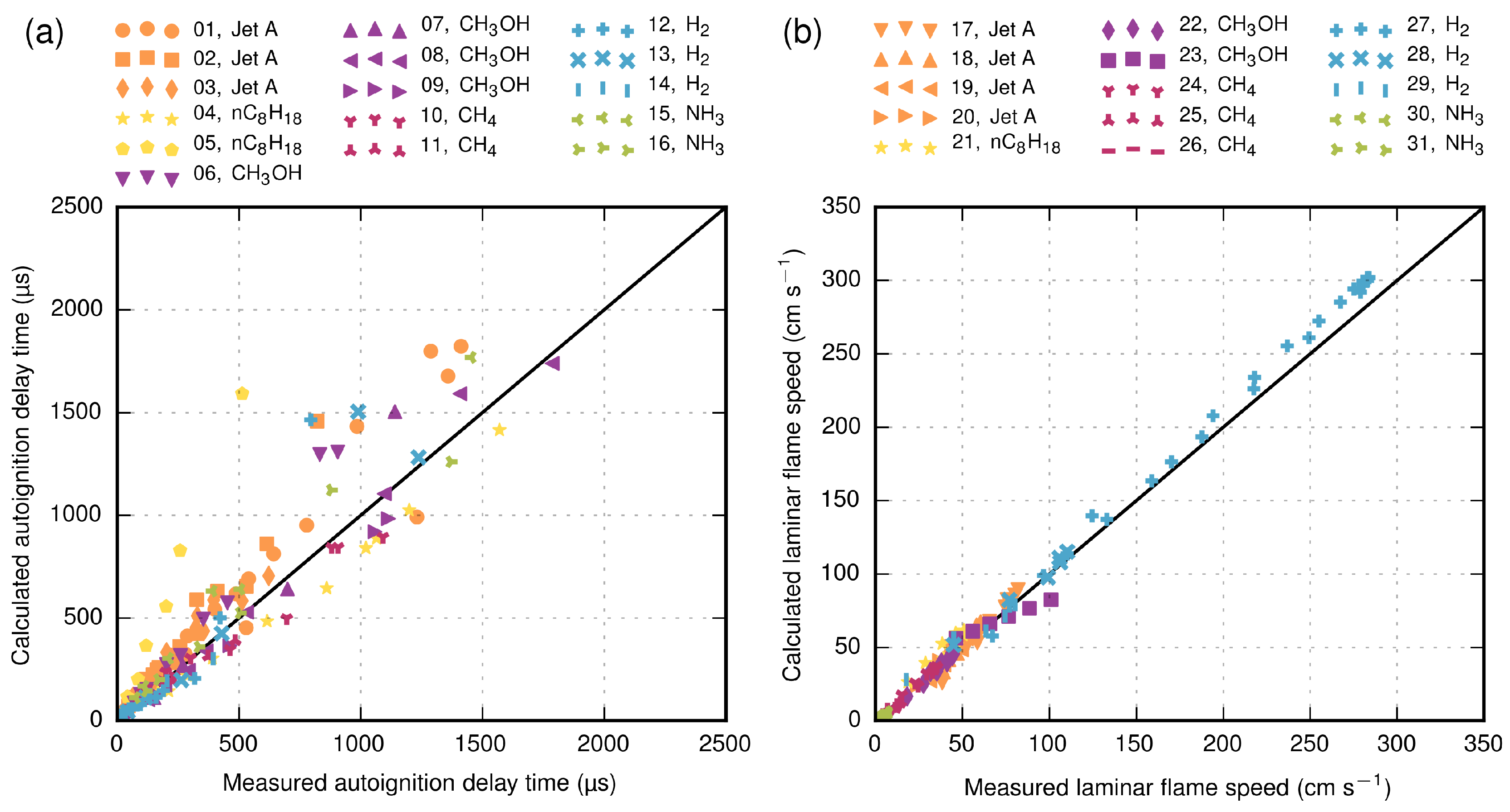
Table 2) at atmospheric conditions, as well as at elevated temperatures (up to 2085 K) and pressures (up to 5.1 MPa). The validation results are shown in Figure 4. All mechanisms are able to predict the experimental data within a mean absolute percentage error of approximately 28% for autoignition delay times and 11% for laminar flame speeds. One exception is Dataset 05 [66], where the deviation is greater. Further validation of the mechanisms used in this study can be found in [54,55,56,57,58].
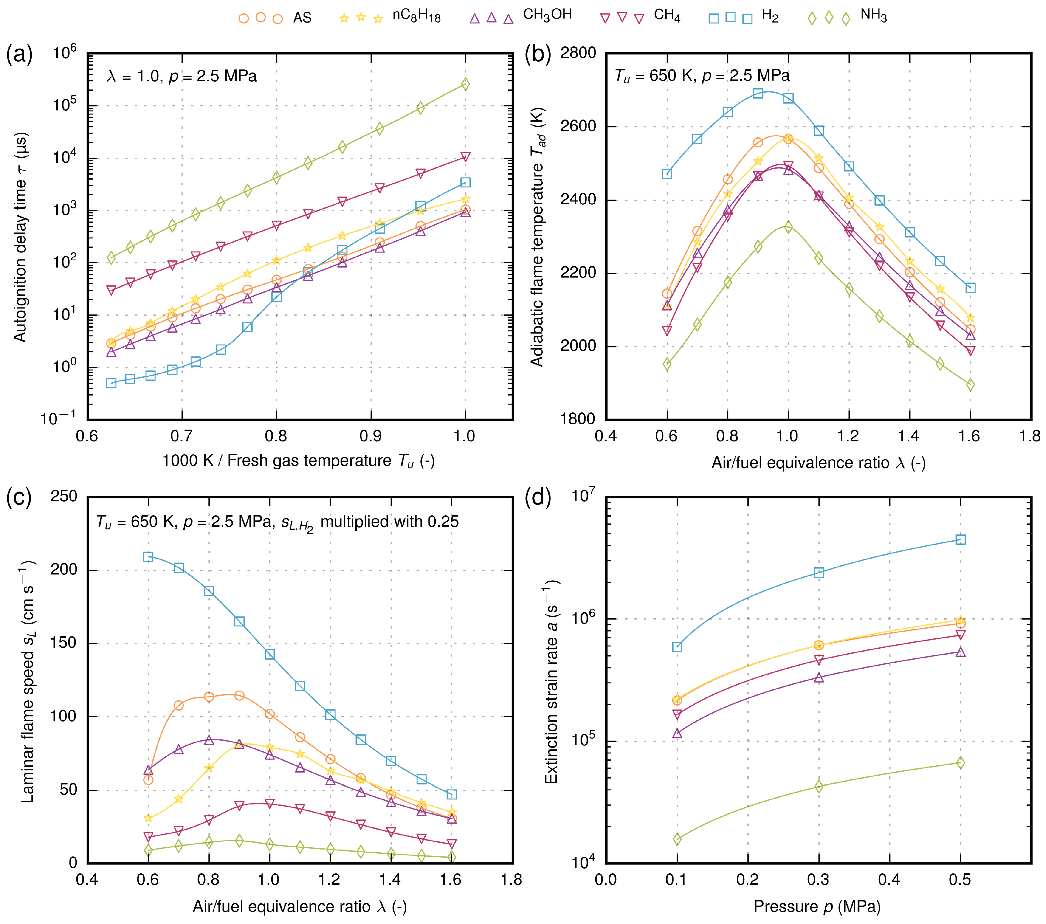
The simulation results of different fuels are depicted in Figure 5. The autoignition delay time is plotted with logarithmic scaling as a function of inverse temperature between 1000 and 1600 K, as is common for Arrhenius-type reaction modeling. The ignition delay time can give some first hints about the reaction rate or ignition energy. For example, fuels with a high autoignition delay time need higher ignition energy to initiate the ignition as quickly as possible, which is important for engine relight during a flameout. Ammonia and methane have the highest autoignition delay time compared to n-octane, followed by jet fuel. Methanol has a slightly lower autoignition delay time, whereas the hydrogen self-ignition behavior strongly depends on the reactants’ temperature. Higher autoignition delay times could enable premixed combustion in aircraft engines.
The adiabatic flame temperature has an impact on the required air for cooling the combustion chamber and the burned hot gases. Further tendencies of emissions such as thermal nitric oxide (NOx) and unburned hydrocarbon are specifically influenced by this property. The temperatures of jet fuel and n-octane are very similar. The same applies for methane and methanol. Ammonia shows the lowest flame temperature of all the investigated fuels, whereas hydrogen has the highest temperature. Looking at just the flame temperature, ammonia has the potential to reduce thermal NOx emissions, but the NOx formation could be promoted by the bounded nitrogen in the fuel molecule, which is so-called fuel NOx. A recent study of a premixed ammonia/air flame shows that the fuel NOx highly depends on the air/fuel equivalence ratio and can be kept rather low [79].
The laminar flame speed plays an important role in the propagation behavior of the flame. Hydrogen has by far the highest flame speed compared to other fuels. In fuel-lean conditions ( λ > 1 ), the flame speeds of jet fuel, n-octane and methanol are similar, but the difference becomes more distinct for fuel-rich conditions ( λ < 1 ). Ammonia has the lowest laminar flame speed of all fuels.
At first glance, this property of ammonia looks rather negative. However, Verkamp et al. [6] suggested partially dissociating ammonia into hydrogen and nitrogen before injection to enhance the combustion, or more precisely, to increase the laminar flame speed. A model for laminar flame speed of NH3/H2/N2 mixtures was very recently developed by Goldmann and Dinkelacker [80] and shows that the flame speed can be adapted in a wide range by the addition of hydrogen to ammonia. New interesting possibilities could be enabled by adjusting the ratio between ammonia and dissociated ammonia (hydrogen + nitrogen) during the operation of the engine. For example, a boost function during take-off could be implemented by a high concentration of hydrogen in the fuel, whereas during cruising, mainly ammonia could be burned.
The extinction strain rate can provide initial information about the flame stability. Fuels with higher extinction strain rates are less sensitive to the risk of flame extinction and allow higher flow velocities in the combustion chamber. Therefore, higher mass flow rates are possible, which results in an increase of thermal power. The extinction strain rate of jet fuel and n-octane is nearly the same. Furthermore, methanol and methane show similarities. Here again, hydrogen has the highest extinction strain rate, whereas ammonia has the lowest. Furthermore, here, a mixture of ammonia with hydrogen could potentially lead to reasonable flame stability.
By comparing the fundamental combustion properties, it can be seen that n-octane is most similar to jet fuel, whereas other fuels show very different behaviors. Therefore, for all these electrofuels, a modification of the combustion chamber and the whole engine would be indispensable. In all cases, hydrogen and ammonia have the maximum and minimum values, respectively. An interesting option, however, could be a mixture of hydrogen and ammonia, as this shows a promising potential to adjust the combustion properties as a function of the mixture.

3.3. Impact of Electrofuels on the Joule Process

Alternative fuels may need other air mass flow rates, and also, other design parameters for the layout of the Joule process (compressor, burning chamber, turbine) can be different. In order to estimate these effects, several thermo-physical parameters have been determined for an aircraft engine, again at an altitude of 10 km ( p 0 = 26,436 Pa, T 0 = 223.15 K) and a cruise speed of M a 
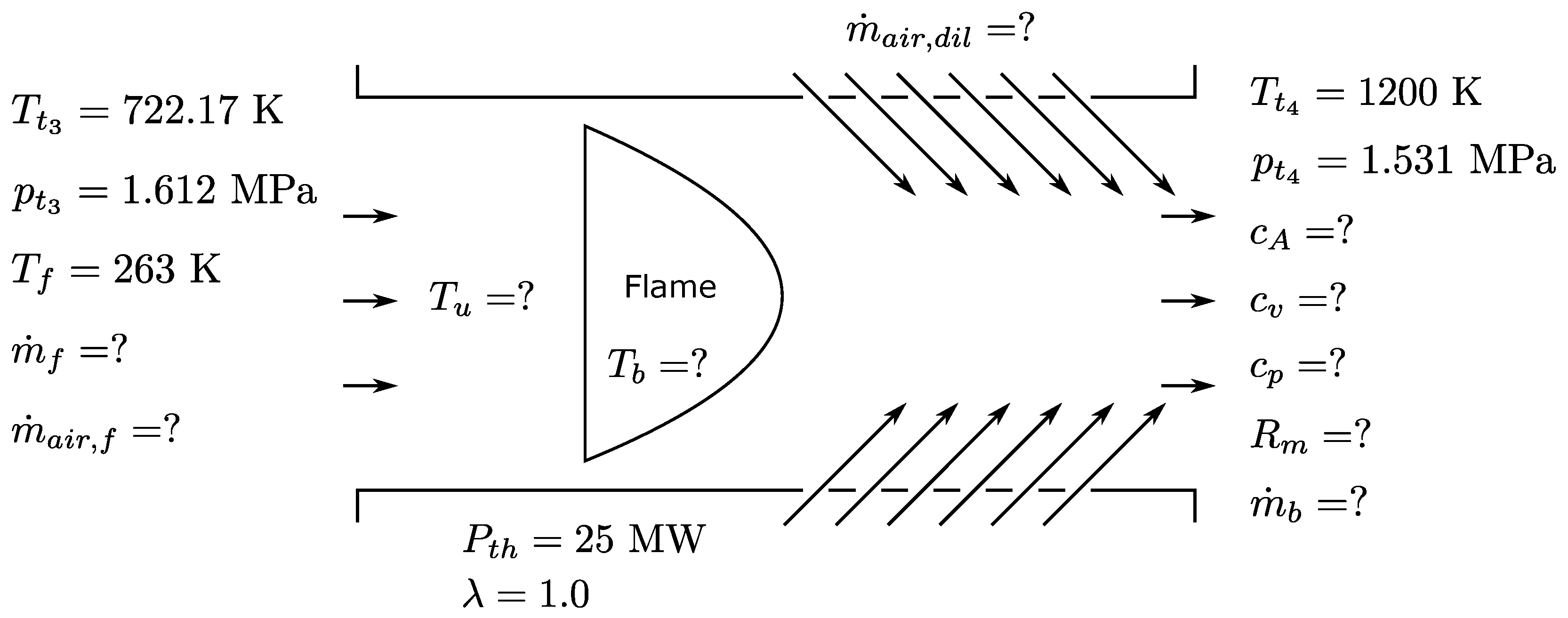
= 0.8. The schematic of the combustion chamber of the aircraft engine and the relevant parameters is given in Figure 6.
The following assumption are applied: The pressure drop across the combustion chamber π C C is assumed to be approximately 5% for all fuels. The turbine inlet temperature T t 4 is held constant at 1200 K, and the necessary overall air mass flow for temperature reduction m ˙ a i r , d i l of the hot burned gases is calculated. The thermal power P t h of the combustion chamber is 25 MW, and premixed combustion with an air/fuel equivalence ratio λ = 1.0 is assumed. The necessary mass flows of fuel m ˙ f and air m ˙ a i r , f for the combustion are calculated. An overall compression ratio C P R = 40 is assumed. The fuel in aircraft is used for cooling the engine oil, and therefore, the fuel is preheated before injection. Here, the inlet fuel temperature T f of 263 K (223 K + 40 K) is chosen. Further ideal gas behavior is assumed. The thermodynamic inlet conditions for the combustion chamber and the turbine are calculated using Equations (1)–(7). The composition and properties of the combustion exhaust gas are calculated using Cantera [59] and the detailed reaction mechanisms in Table 2. The following indices are used: 0: environment, 1: turbo fan inlet, 2: compressor inlet, 3: combustion chamber inlet, 4: turbine inlet, 5: turbine exit. Table 4 shows the calculated values of the respective Positions 0–4.
p t 1 = p 0 · 1 + κ 1 2 M a 0 2 κ κ 1
T t 1 = T 0 · 1 + κ 1 2 · M a 0 2
p t 2 = π Inlet · p t 1 with π Inlet = 0.999
T t 2 = T t 1 · p t 2 p t 1 κ 1 κ
p t 3 = C P R · p t 2 with C P R = 40
T t 3 = T t 2 · p t 3 p t 2 κ 1 κ
p t 4 = π C C · p t 3 with π C C = 0.95
The speed of sound c A (Equation (8)) can give the first indication about the maximal mass flow at the combustor exit and with that the performance output.
c A = κ · R m · T with κ = c p c v and R m = R M ¯
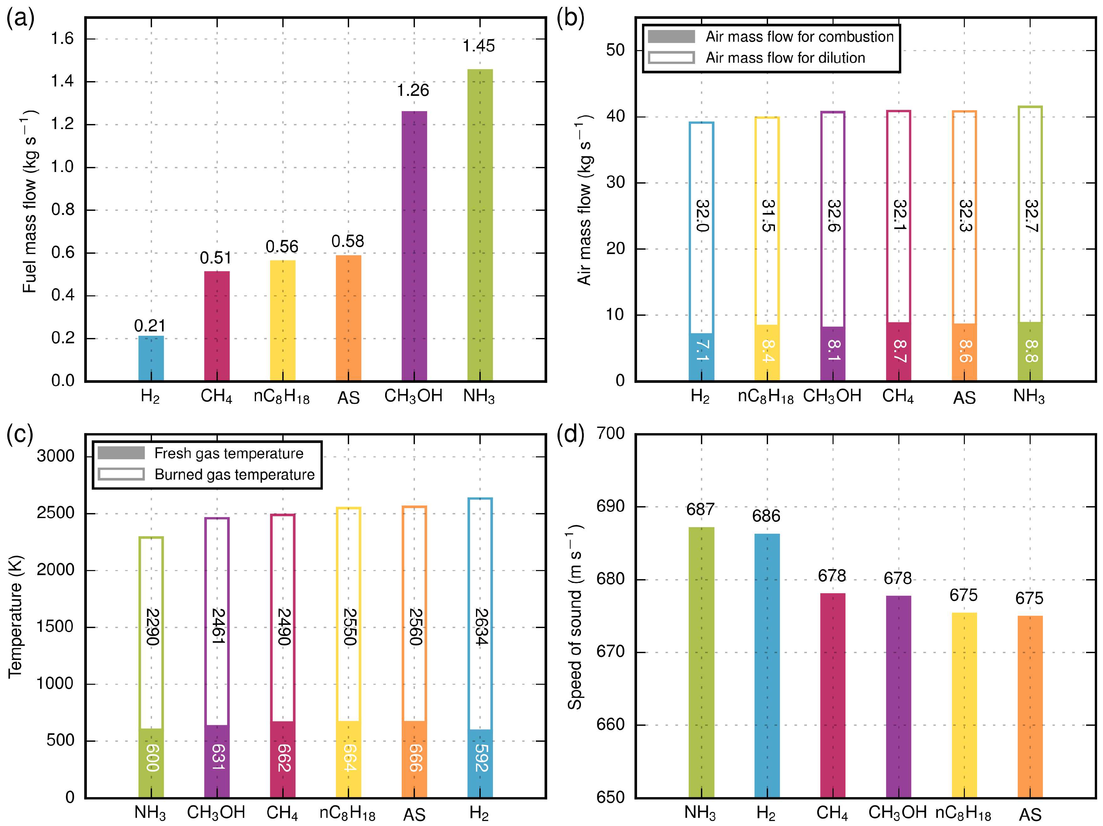
The results of the calculations are depicted in Figure 7 and Table 5. It can be clearly seen that the fuel consumption is different due to the specific energy of fuels. The total inlet mass flow of air for combustion and dilution is nearly the same for all fuels due to the effect of cooling capacity and adiabatic flame temperature. Hydrogen has the highest flame temperature, but also the highest specific heat capacity c p , c v of the burned gas. The heat capacity ratio κ is nearly the same for all fuels. The speed of sound of all fuels is similar due to the high air content in the burned gas. Hydrogen and ammonia have a slightly higher speed of sound due to the lower mean molecular weight of products M ¯ in the burned gas. The dynamic viscosity μ and thermal conductivity λ c o n d are nearly the same. In summary, all input and output parameters for different electrofuels are nearly similar, except the fuel mass flow.
The detailed analysis of the necessary burner concept with details on the fuel/air supply, mixing system and flame stabilization is outside the scope of this study.

4. Turbine Performance Investigation

4.1. Introduction

In the following section, the influence of electrofuels on turbine performance is investigated and compared to conventional kerosene in the form of Jet A-1. Because the turbine operates in a choked condition, mass flow cannot be independently altered, and the turbine is operated at a fixed operating point, which differs from the one of the previous section. The objective of this investigation is the assessment of the drop-in potential of the introduced fuels, that is, a performance investigation for the turbine operating at a constant design point and without any modifications to the geometry. A theoretical framework to assess the impact of gas composition on performance is derived and supplemented with results from 3D numerical simulations.

4.2. Basic Setup

The turbine investigated was designed for mid-to-long-range aircraft and is depicted in the cross-section in Figure 8. The computational single-passage domain begins at the combustion chamber outlet and ends downstream of the exit guide vane (EGV). The two-stage high pressure turbine (HPT) is separated from the five-stage low pressure turbine (LPT) by an inter-turbine duct. The geometry is simplified by excluding cavities and fillets. Neglecting fillets increases the mass flow by 0.8% as a result of the larger flow area. Cooling mass flows are not considered because the solver used does not allow for the mixing of different gases, which, based on previous sensitivity studies, leads to an offset of the calculated power by 4.7%. Both of these errors are systematic in nature and will only offset the calculated performance parameters, while not affecting the study itself.
The design point investigated is a modified cruise rating with reduced shaft speed to account for the lack of cooling mass flow entering the low pressure turbine. The relevant machine parameters at this operating point are summarized in Table 6. Reduced mass flow, pressure ratio and reduced engine speed are kept constant for all of the calculations below.

4.3. Numerical Model

The flow solver TRACE [82] was used for steady-state calculations of the turbine geometry. TRACE is being developed by the German Aerospace Center (DLR) in cooperation with MTU Aero Engines AG. The Wilcox (1988) k- ω -model [83] with the Kato–Launder fix [84] to correct the turbulent kinetic energy production near the stagnation point was used to model turbulence. Rotor and stator walls were fully resolved for which a low Reynolds formulation of the turbulence model was used. Hub and tip endwalls were not resolved; instead, wall functions were used. All boundary layers were treated as fully turbulent, i.e., transition was not modeled in the presented calculations.
A detailed description of the computational grid (Figure 8) can be found in [81]. The blocking topology, consisting of an O-grid around the blade joined by H, C and G-grids in the passage, is depicted for the first HPT stage in Figure 8 and similar for every row. The dimensionless wall distance y + is below one for the low-Reynolds walls and between 10 and 30 for the non-resolved walls. A grid convergence study using the Grid Convergence Index defined by Roache [85] was also conducted by [81]. It is shown that the relative error decreases with discretization size and that the grid used in the present work yields an extrapolated Richardson result (EERE) of 0.0933 for the first high pressure turbine stage.
A mixing-plane approach was used for inter-row coupling. Constant turbine inlet and outlet boundary conditions were specified according to the turbine’s design point. The turbulence intensity at the inlet was assumed to be 5% and the length scale 2.08 × 10⁻⁴ m. The exhaust gas was modeled as an ideal gas with caloric properties obtained with the method presented in Section 3 for the inlet total pressure given in Table 6. With the present setup, it was not possible to allow for viscosity variation based on gas composition; the Sutherland model [86] for air was used for all calculations. Viscosity influences on friction and transition can therefore not be evaluated.

4.4. Initial Considerations

The turbine operates in choked condition at the investigated operating point, resulting in a fixed reduced mass flow:
m ˙ red , 4 = m ˙ 4 R T t 4 κ p t 4 A
through the HPT. For constant flow area and turbine inlet parameters, the mass flow can be directly related to the gas composition:
m ˙ 4 κ R
Assuming constant pressure and temperature, the exhaust gas density will actually relate to the gas constant as:
ρ 1 R
which means that the axial flow velocity will grow if the mass flow is reduced due to a higher gas constant, e.g., due to a lower average molecular weight of the exhaust gas. Reduced speed:
n red = n κ R T t 4
is kept constant for all fuels; shaft speed is adjusted for each fuel investigated and thus proportional to κ R . Because a fixed operating point with similar velocity triangles will ideally result in a constant polytropic efficiency:
η p = κ κ 1 ln T t 5 T t 4 ln p t 5 p t 4
the outlet total temperature can be correlated as:
T t 5 = T t 4 p t 5 p t 4 η p κ 1 κ
The turbine power:
P T = m ˙ 4 c p T ( T t 4 T t 5 )
can then be related to:
P T κ R κ R κ 1 ( T t 4 T t 5 ) κ 3 R κ 1 1 Π η p κ 1 κ

4.5. Discussion of Turbine Performance

Table 7 lists the results of the numerical simulations of the turbine process for the different fuel types. Shown is the calculated resulting turbine mass flow rate m ˙ 4 , the resulting low pressure turbine speed n LPT , the total temperature at turbine exit T t 5 , the turbine power P T and the polytropic turbine efficiency η p . The relevant gas properties are also repeated here.
For all fuels, the ratio κ R is lower than that of Jet A-1, which results in proportionally lower mass flows. The inverse is true for the factor κ R , which results in higher engine speeds. Turbine power output increases almost linearly with R , due to the weaker variation in the ratios of specific heats. The change in total temperature agrees fully with the correlation presented above. Polytropic efficiency varies by less than 0.01%, which can be treated as constant within the limits of numerical accuracy. As can be seen in Figure 9, NH3 offers the highest increase in power output over Jet A-1 at almost 2%.
The increase in power output, however, comes at the cost of a nearly similar increase in shaft speed. This has a negative impact on the engine by increasing structural stresses, as well as blade tip speed, the latter being specifically critical for the high-diameter fan. Initially, CH3OH appears to offer the best compromise due to its low ratio of specific heats resulting in a small increase in engine speed relative to the gain in power output. However, the aerodynamic forces acting on the blade, which can be related to the blade loading as defined by Traupel [87]:
Ψ = Δ h t u 2 = c p u 2 ( T t , in T t , out ) ,
will increase for lower ratios of specific heats. As a result, overall structural loads were found to be proportional to the power output, thus diminishing the perceived advantage of lower ratios of specific heats. Considering the discussion above, the possibility of adjusting the operating point towards lower engine speeds was also investigated. Since the turbine operates in choked condition, a decrease in engine speed will not be matched by an equivalent decrease in absolute mass flow. Considering Equation (17) and the flow coefficient:
Φ = v x u
reveals that both will increase for constant shaft speed and blade velocity u due to the higher axial velocity v x and specific heat c p resulting from the gas properties of all electrofuel mixtures. Increasing both blade loading and flow coefficient results in a lower efficiency due to higher pressure losses and stronger secondary flows [88]. Additionally, negative incidence at the rotor leading edges was found as a result of the altered velocity ratio.
The change in engine speed and blade loading requires a more detailed investigation regarding structural and aerodynamic loads and possibly an optimized turbine design. With the above discussion in mind, some design recommendations can be derived. First, the increasing structural loads have to be counteracted by augmented components, such as sturdier disks and smaller diameters. The change in blade loading would also require an optimized blade geometry. If the design point is altered towards a constant engine speed, blade orientation has to be optimized additionally, to counteract negative incidence.

5. Comparative Discussion

The major results of this study are collected to rate the investigated electrofuels via an evaluation matrix (Table 8) in order to show the potentials. The electrofuels are compared for each criterion to jet fuel. The evaluation is based on the data known so far, as described in the text above. As some of the details are not yet fully known, the evaluation has to be seen as preliminary.
The first criterion is the potential overall CO2 impact, being problematic for the reference fuel from fossil source, while being good for the carbon-containing, but sustainable electrofuels and being excellent for the carbon-free fuels. The electro-synthesis criterion contains the availability of the feedstock, the energy demand of the synthesis and the availability of the technology. The specific energy (per mass) and the volumetric energy density determine the transportability and the storage problem in aviation. The storage problem is a challenge specifically for CH4 and specifically problematic for hydrogen. Toxicity is problematic for NH3 and CH3OH, but also, the common fuel so far is not fully free of this issue. The combustion properties contain the reactivity and stability. As these values are rather low for NH3, the very interesting option of mixtures of NH3 and H2 is included in this table, allowing the reactive properties to be adapted within a broad range [80]. This may allow one also to reduce the soot and NOx emissions, which are considered unsatisfactory for the common fuel Jet A-1 and other drop-in fuels based on the conventional spray-jet combustor, while with gaseous fuels, eventually lean premixed combustion is possible with significantly reduced emissions. However, this would require major modifications of the combustor, which is considered a negative issue in the drop-in capability with respect to combustion. For the turbine, three criteria are listed with the turbine power output always being very good, specifically for H2 and NH3. With the increase in engine speed, however, a clear cost was also identified, as the turbine geometry would require significant adaptations. With that, the drop-in potential with regard to turbine performance is specifically given for n-octane, due its very similar properties to that of jet fuel, and to a lesser degree for CH3OH and CH4. Based on the overall evaluation, the most promising substitute fuel for current aircraft design is n-octane due to its very similar properties to that of jet fuel. For the other electrofuels, several challenging issues have to be solved. Here, the mixtures of fuels, like those mentioned in the table, could be an interesting option with the aim to increase the positive properties and to reduce the problematic ones.

6. Conclusions, Challenges and Future Research

Alternative and sustainable so-called electrofuels, i.e., n-octane, methanol, methane, hydrogen and ammonia, were investigated regarding their synthesis, combustion and their impact on a combustion chamber and turbine. Furthermore, the potential of ammonia/hydrogen mixtures was mentioned.

6.1. Synthesis of Electrofuels

For the synthesis of electrofuels, various pathways are possible. They are compared in terms of efficiency. The hydrogen evolution reaction plays a main role in most of the current processes. It is followed by reforming steps to increase the storage capabilities or to shape the combustion parameters of the electrofuel to the desired values. New one-step reactions are needed to bypass the production and the storage of hydrogen to raise the energy efficiency further. Electrochemical pathways can be, given the appropriate technology readiness, more efficient than conventional processes and are needed to steer the demand of electricity in a way that new regenerative energies can handle. All electrochemical pathways are, in terms of technology readiness, far behind, but have the potential for the creation of tailor-made emission-free aviation fuels with renewable energies.

6.2. Combustion Characteristics

The fundamental combustion properties, i.e., autoignition delay time, adiabatic flame temperature, laminar flame speed and extinction strain rates, were computed using detailed reaction mechanism and were compared with conventional jet fuel. Results show that all investigated electrofuels, except n-octane, differ significantly from jet fuel regarding their combustion properties. For a combustion chamber case under typical aviation conditions, several important parameters were calculated for a constant cruise operating point. The mass flows of air for combustion and cooling the burned hot gases are nearly the same, whereas the mass flow of fuel differs due to the specific energy. The reaction reactivity is given for most of the fuels, except for ammonia. Here, mixture approaches (ammonia/hydrogen mixture) might be of special interest, where more research is needed. The design of combustors has to be adapted to the fuels, requiring basic research on flame stabilization and emission. Although this process will need great effort, it provides the chance to reduce the emission of soot and nitrogen oxide, if the combustion were based on more advanced approaches, like lean premixed or partially-premixed combustion. Here, however, flashback studies are required, as well as reignition studies in order to fulfill necessary safety margins on combustion stability.

6.3. Turbine Performance

The influence of fuel choice on turbine performance was investigated at a modified cruise operating point. As a consequence of the reduced mass flow and the reduced engine speed remaining constant, absolute mass flow decreased and absolute rotational speed increased. A higher power output and higher shaft speed were observed for all fuels investigated. Polytropic efficiency remained constant within the limits of numerical approximation. The results show that the alternative fuels considered here may be used in current turbine designs without major performance impacts. With regard to the aerothermodynamics of the hot gas path, they can even be used with current designs. With regard to the turbomachinery design, however, the increase in rotor speed changes the mechanical loads and thus requires modifications in the mechanical design. The fuels therefore are not drop-in options, but appear to be alternatives worth further evaluation with regard to the upstream fuel supply chain and, if that turns out promising, with regard to a more detailed component design for the compressor, the combustor and the turbine of the aeroengine.

6.4. Conclusive Remarks

This study on electrofuels for use in aviation demonstrates potentials, as well as challenges. The ideal electrofuel will have the potential to allow sustainable aviation with fully-renewable fuel, where the greenhouse gas impact is zero and where the pollutant emissions are lowered. Electrofuels allow the combination of green electricity being stored with high energy content in liquid or gaseous fuels. The production can be decoupled from the utilization both in time, giving a contribution to the energy storage problem of renewable solar and wind electricity, as well as in space, as liquid and gaseous electrofuels have good or excellent transport properties. The utilization of electrofuels in current aviation engine technologies could be possible with drop-in fuels, where n-octane shows the best potential so far. The synthetic production (ideally with an all-electrochemical pathway with advantages to be delocalized) needs, however, significant research until technological readiness is achieved. Other potential electro-fuels are discussed, and a preliminary comparison is done in the different categories. Some of them may give the opportunity to reduce the pollutant emissions within the aviation engines significantly, if lean premixed combustion were possible, where, however, more fundamental research and safety issues have to be addressed. Of special interest could be mixtures like that of hydrogen/ammonia. With regard to the turbine design, the drop-in fuel like n-octane shows the potential to be used within current turbine generations, while other alternative fuels modify the aerothermodynamics and the aeromechanical needs and, thus, will require corresponding modifications in the design.

Acknowledgments

This research was supported by the Lower Saxonian Ministry for Science and Culture as part of the research program MOBILISE (Mobility in Engineering and Science). The authors gratefully acknowledge the substantial contribution of the DLR Institute of Propulsion Technology and MTU Aero Engines AG for providing the TRACE code.

Author Contributions

All authors contributed jointly to the paper. Topical focus was as follows: combustion and overall evaluation: A.G. and F.D.; electrofuels: W.S. and U.S.; turbine processes: M.O. and T.K.; jet propulsion: J.R.S. and J.F.

Conflicts of Interest

The authors declare no conflict of interest.

References

  1. Ridjan, I.; Mathiesen, B.V.; Connolly, D. Terminology used for renewable liquid and gaseous fuels based on the conversion of electricity: A review. J. Clean. Prod. 2016, 112, 3709–3720. [Google Scholar] [CrossRef]
  2. Correa, S.M. A Review of NOx Formation Under Gas-Turbine Combustion Conditions. Combust. Sci. Technol. 1993, 87, 329–362. [Google Scholar] [CrossRef]
  3. Zhang, C.; Hui, X.; Lin, Y.; Sung, C.J. Recent development in studies of alternative jet fuel combustion: Progress, challenges, and opportunities. Renew. Sustain. Energy Rev. 2016, 54, 120–138. [Google Scholar] [CrossRef]
  4. Newhall, H.K.; Starkman, E.S. Theoretical Performance of Ammonia as a Gas Turbine Fuel; SAE Technical Paper; SAE International: Warrendale, PA, USA, 1966. [Google Scholar]
  5. Pratt, D.T. Performance of Ammonia-Fired Gas-Turbine Combustors; Technical Report; DTIC Document; University of California: Berkeley, CA, USA, 1967. [Google Scholar]
  6. Verkamp, F.J.; Hardin, M.C.; Williams, J.R. Ammonia Combustion Properties and Performance in Gas-Turbine Burners; Symposium (International) on Combustion; Elsevier: Amsterdam, The Netherlands, 1967; Volume 11, pp. 985–992. [Google Scholar]
  7. Stillwell, W.H. X-15 Research Results; Technical Report; National Aeronautics and Space Administration: Washington, DC, USA, 1965. [Google Scholar]
  8. Iki, N.; Kurata, O.; Matsunuma, T.; Inoue, T.; Suzuki, M.; Tsujimura, T.; Furutani, H. Micro Gas Turbine Firing Kerosene and Ammonia. In Proceedings of the ASME Turbo Expo 2015: Turbine Technical Conference and Exposition, Montreal, QC, Canada, 15–19 June 2015; Volume 8, p. V008T23A023. [Google Scholar]
  9. Kurata, O.; Iki, N.; Matsunuma, T.; Inoue, T.; Tsujimura, T.; Furutani, H.; Kobayashi, H.; Hayakawa, A. Performances and emission characteristics of NH3–air and NH3–CH4–air combustion gas-turbine power generations. Proc. Combust. Inst. 2017, 36, 3351–3359. [Google Scholar] [CrossRef]
  10. Brewer, G. Aviation usage of liquid hydrogen fuel—Prospects and problems. Int. J. Hydrogen Energy 1976, 1, 65–88. [Google Scholar] [CrossRef]
  11. Brewer, G. Hydrogen usage in air transportation. Int. J. Hydrogen Energy 1978, 3, 217–229. [Google Scholar] [CrossRef]
  12. Winter, C.J. Hydrogen in high-speed air transportation. Int. J. Hydrogen Energy 1990, 15, 579–595. [Google Scholar] [CrossRef]
  13. Price, R.O. Liquid hydrogen—An alternative aviation fuel? Int. J. Hydrogen Energy 1991, 16, 557–562. [Google Scholar] [CrossRef]
  14. Pohl, H.W.; Malychev, V.V. Hydrogen in future civil aviation. Int. J. Hydrogen Energy 1997, 22, 1061–1069. [Google Scholar] [CrossRef]
  15. Schmidtchen, U.; Behrend, E.; Pohl, H.W.; Rostek, N. Hydrogen aircraft and airport safety. Renew. Sustain. Energy Rev. 1997, 1, 239–269. [Google Scholar] [CrossRef]
  16. Klug, H.G.; Faass, R. CRYOPLANE: Hydrogen fuelled aircraft - status and challenges. Air Space Eur. 2001, 3, 252–254. [Google Scholar] [CrossRef]
  17. Komissarov, D. Tupolev Tu-154: The USSR’s Medium-Range Jet Airliner; Midland Publishing Limited: Milbank, SD, USA, 2006. [Google Scholar]
  18. Contreras, A.; Yiğit, S.; Özay, K.; Veziroğlu, T. Hydrogen as aviation fuel: A comparison with hydrocarbon fuels. Int. J. Hydrogen Energy 1997, 22, 1053–1060. [Google Scholar] [CrossRef]
  19. Corchero, G.; Montañés, J.L. An approach to the use of hydrogen for commercial aircraft engines. Proc. Inst. Mech. Eng. Part G J. Aerosp. Eng. 2005, 219, 35–44. [Google Scholar] [CrossRef] [Green Version]
  20. Janic, M. Is liquid hydrogen a solution for mitigating air pollution by airports? Int. J. Hydrogen Energy 2010, 35, 2190–2202. [Google Scholar] [CrossRef]
  21. Verstraete, D.; Hendrick, P.; Pilidis, P.; Ramsden, K. Hydrogen fuel tanks for subsonic transport aircraft. Int. J. Hydrogen Energy 2010, 35, 11085–11098. [Google Scholar] [CrossRef]
  22. lYılmaz, İ.; İlbaş, M.; Taştan, M.; Tarhan, C. Investigation of hydrogen usage in aviation industry. Energy Convers. Manag. 2012, 63, 63–69. [Google Scholar] [CrossRef]
  23. Verstraete, D. Long range transport aircraft using hydrogen fuel. Int. J. Hydrogen Energy 2013, 38, 14824–14831. [Google Scholar] [CrossRef]
  24. Khandelwal, B.; Karakurt, A.; Sekaran, P.R.; Sethi, V.; Singh, R. Hydrogen powered aircraft: The future of air transport. Prog. Aerosp. Sci. 2013, 60, 45–59. [Google Scholar] [CrossRef]
  25. Pereira, S.R.; Fontes, T.; Coelho, M.C. Can hydrogen or natural gas be alternatives for aviation?—A life cycle assessment. Int. J. Hydrogen Energy 2014, 39, 13266–13275. [Google Scholar] [CrossRef]
  26. Janić, M. Greening commercial air transportation by using liquid hydrogen (LH2) as a fuel. Int. J. Hydrogen Energy 2014, 39, 16426–16441. [Google Scholar] [CrossRef]
  27. Verstraete, D. On the energy efficiency of hydrogen-fuelled transport aircraft. Int. J. Hydrogen Energy 2015, 40, 7388–7394. [Google Scholar] [CrossRef]
  28. Cecere, D.; Giacomazzi, E.; Ingenito, A. A review on hydrogen industrial aerospace applications. Int. J. Hydrogen Energy 2014, 39, 10731–10747. [Google Scholar] [CrossRef]
  29. Sehra, A.K.; Whitlow, W. Propulsion and power for 21st century aviation. Prog. Aerosp. Sci. 2004, 40, 199–235. [Google Scholar] [CrossRef]
  30. Edwards, T.; Moses, C.; Dryer, F. Evaluation of Combustion Performance of Alternative Aviation Fuels. In Proceedings of the 46th AIAA/ASME/SAE/ASEE Joint Propulsion Conference & Exhibit, American Institute of Aeronautics and Astronautics, Nashville, TN, USA, 25–28 July 2010. [Google Scholar]
  31. Yilmaz, N.; Atmanli, A. Sustainable alternative fuels in aviation. Energy 2017, 140, 1378–1386. [Google Scholar] [CrossRef]
  32. Bicer, Y.; Dincer, I. Life cycle evaluation of hydrogen and other potential fuels for aircrafts. Int. J. Hydrogen Energy 2017, 42, 10722–10738. [Google Scholar] [CrossRef]
  33. Salem, R.R. The electrolysis of water. J. Electroanal. Chem. 1999, 476, 92–93. [Google Scholar]
  34. Gülker, F. Production of hydrogen (Herstellung von Wasserstoff). Patent DE446488 (GB), July 1927. [Google Scholar]
  35. Ruth, M.; Laffen, M.; Timbario, T. Hydrogen Pathways: Cost, Well-to-Wheels Energy Use, and Emissions for the Current Technology Status of Seven Hydrogen Production, Delivery, and Distribution Scenarios; NREL: Golden, CO, USA, 2009; p. 55. [Google Scholar]
  36. Crabtree, G.W.; Dresselhaus, M.S.; Buchanan, M.V. The Hydrogen Economy. Phys. Today 2004, 57, 39–45. [Google Scholar] [CrossRef]
  37. Sap, K.A.; Demmers, J.A.A.; Nimit Patel, G.R. The energy efficiency of onboard hydrogen storage. Intech 2012, 6, 111–133. [Google Scholar]
  38. Caulfield, R.A.R.; Willis, S.; Grimm, B.; Box, P.O.; Townsend, P.; Address, P.; Street, O. Solid State Ammonia Synthesis (SSAS) Pilot Plant Demonstration System for Renewable Energy (RE) Firming Storage, Transmission, and Export; Alaska Applied Sciences, Inc.: Juneau, AK, USA, 2011; pp. 1–5. [Google Scholar]
  39. Zacharakis-Jutz, G.E.; Kong, S.C. Performance Characteristics of Ammonia Engines Using Direct Injection Strategies. Ph.D. Thesis, Iowa State University, Ames, IA, USA, 2013. [Google Scholar]
  40. Zamfirescu, C.; Dincer, I. Ammonia as a green fuel and hydrogen source for vehicular applications. Fuel Process. Technol. 2009, 90, 729–737. [Google Scholar] [CrossRef]
  41. Amar, I.A.; Lan, R.; Petit, C.T.; Tao, S. Solid-state electrochemical synthesis of ammonia: A review. J. Solid State Electrochem. 2011, 15, 1845–1860. [Google Scholar] [CrossRef]
  42. Liu, Y.; Zhang, Y.; Chen, K.; Quan, X.; Fan, X.; Su, Y.; Chen, S.; Zhao, H.; Zhang, Y.; Yu, H.; Hoffmann, M.R. Selective electrochemical reduction of CO2 to ethanol on B and N codoped nanodiamond. Angew. Chem. Int. Ed. 2017, 56, 15607–15611. [Google Scholar] [CrossRef] [PubMed]
  43. Kuhl, K.P.; Hatsukade, T.; Cave, E.R.; Abram, D.N.; Kibsgaard, J.; Jaramillo, T.F. Electrocatalytic conversion of carbon dioxide to methane and methanol on transition metal surfaces. J. Am. Chem. Soc. 2014, 136, 14107–14113. [Google Scholar] [CrossRef] [PubMed]
  44. Yuan, J.; Liu, L.; Guo, R.R.; Zeng, S.; Wang, H.; Lu, J.X. Electroreduction of CO2 into Ethanol over an Active Catalyst: Copper Supported on Titania. Catalysts 2017, 7, 220. [Google Scholar] [CrossRef]
  45. Studt, F.; Sharafutdinov, I.; Abild-Pedersen, F.; Elkjær, C.F.; Hummelshøj, J.S.; Dahl, S.; Chorkendorff, I.; Nørskov, J.K. Discovery of a Ni-Ga catalyst for carbon dioxide reduction to methanol. Nat. Chem. 2014, 6, 320–324. [Google Scholar] [CrossRef] [PubMed]
  46. Gattrell, M.; Gupta, N.; Co, A. A review of the aqueous electrochemical reduction of CO2 to hydrocarbons at copper. J. Electroanal. Chem. 2006, 594, 1–19. [Google Scholar] [CrossRef]
  47. Nilges, P.; Schröder, U. Electrochemistry for biofuel generation: production of furans by electrocatalytic hydrogenation of furfurals. Energy Environ. Sci. 2013, 6, 2925–2931. [Google Scholar] [CrossRef]
  48. Elliott, D.C. Conversion of Biomass Wastes to Levulinic Acid and Derivatives. Available online: https://www.pnnl.gov/biobased/docs/mthf.pdf (accessed on 31 January 2018).
  49. Rackemann, D.W.; Doherty, W.O.S. The conversion of lignocellulosics to levulinic acid. Biofuels Bioprod. Biorefin. 2011, 5, 198–214. [Google Scholar] [CrossRef] [Green Version]
  50. Lange, J.P.; Price, R.; Ayoub, P.M.; Louis, J.; Petrus, L.; Clarke, L.; Gosselink, H. Valeric Biofuels: A Platform of Cellulosic Transportation Fuels. Angew. Chem. 2010, 122, 4581–4585. [Google Scholar] [CrossRef]
  51. Serrano-Ruiza, J.C.; Bradena, D.J.; Westa, R.M.; Dumesic, J.A.; Serrano-Ruiz, J.C.; Braden, D.J.; West, R.M.; Dumesic, J.A. Conversion of cellulose to hydrocarbon fuels by progressive removal of oxygen. Appl. Catal. B Environ. 2010, 100, 184–189. [Google Scholar] [CrossRef]
  52. Nilges, P.; dos Santos, T.R.; Harnisch, F.; Schröder, U. Electrochemistry for biofuel generation: Electrochemical conversion of levulinic acid to octane. Energy Environ. Sci. 2012, 5, 5231–5235. [Google Scholar] [CrossRef]
  53. IFA. Gefahrstoffe—Datenbanken (GESTIS). Available online: http://www.dguv.de/ifa/gestis/index.jsp (accessed on 31 January 2018).
  54. Honnet, S.; Seshadri, K.; Niemann, U.; Peters, N. A surrogate fuel for kerosene. Proc. Combust. Inst. 2009, 32, 485–492. [Google Scholar] [CrossRef]
  55. Westbrook, C.K.; Pitz, W.J.; Herbinet, O.; Curran, H.J.; Silke, E.J. A comprehensive detailed chemical kinetic reaction mechanism for combustion of n-alkane hydrocarbons from n-octane to n-hexadecane. Combust. Flame 2009, 156, 181–199. [Google Scholar] [CrossRef]
  56. Burke, S.M.; Metcalfe, W.; Herbinet, O.; Battin-Leclerc, F.; Haas, F.M.; Santner, J.; Dryer, F.L.; Curran, H.J. An experimental and modeling study of propene oxidation. Part 1: Speciation measurements in jet-stirred and flow reactors. Combust. Flame 2014, 161, 2765–2784. [Google Scholar] [CrossRef]
  57. Burke, S.M.; Burke, U.; Donagh, R.M.; Mathieu, O.; Osorio, I.; Keesee, C.; Morones, A.; Petersen, E.L.; Wang, W.; DeVerter, T.A.; et al. An experimental and modeling study of propene oxidation. Part 2: Ignition delay time and flame speed measurements. Combust. Flame 2015, 162, 296–314. [Google Scholar] [CrossRef]
  58. Mathieu, O.; Petersen, E.L. Experimental and modeling study on the high-temperature oxidation of Ammonia and related NOx chemistry. Combust. Flame 2015, 162, 554–570. [Google Scholar] [CrossRef]
  59. Goodwin, D.G.; Moffat, H.K.; Speth, R.L. Cantera: An Object-oriented Software Toolkit for Chemical Kinetics, Thermodynamics, and Transport Processes, version 2.3.0; California Institute of Technology: Pasadena, CA, USA, 2017. [Google Scholar]
  60. Fiala, T.; Sattelmayer, T. Nonpremixed Counterflow Flames: Scaling Rules for Batch Simulations. J. Combust. 2014, 2014, 484372. [Google Scholar] [CrossRef]
  61. Vasu, S.S.; Davidson, D.F.; Hanson, R.K. Jet fuel ignition delay times: Shock tube experiments over wide conditions and surrogate model predictions. Combust. Flame 2008, 152, 125–143. [Google Scholar] [CrossRef]
  62. Vukadinovic, V.; Habisreuther, P.; Zarzalis, N. Experimental Study on Combustion Characteristics of Conventional and Alternative Liquid Fuels. J. Eng. Gas Turbines Power 2012, 134, 121504. [Google Scholar] [CrossRef]
  63. Wang, H.; Oehlschlaeger, M.A. Autoignition studies of conventional and Fischer–Tropsch jet fuels. Fuel 2012, 98, 249–258. [Google Scholar] [CrossRef]
  64. Hui, X.; Sung, C.J. Laminar flame speeds of transportation-relevant hydrocarbons and jet fuels at elevated temperatures and pressures. Fuel 2013, 109, 191–200. [Google Scholar] [CrossRef]
  65. Davidson, D.F.; Ranganath, S.C.; Lam, K.Y.; Liaw, M.; Hong, Z.; Ronald K., H. Ignition Delay Time Measurements of Normal Alkanes and Simple Oxygenates. J. Propul. Power 2010, 26, 280–287. [Google Scholar] [CrossRef]
  66. Oehlschlaeger, M.A. The Oxidation and Ignition of Jet Fuels; Technical Report; Rensselaer Polytechnic Institute Troy United States: Troy, NY, USA, 2017. [Google Scholar]
  67. Ji, C.; Dames, E.; Wang, Y.L.; Wang, H.; Egolfopoulos, F.N. Propagation and extinction of premixed C5–C12 n-alkane flames. Combust. Flame 2010, 157, 277–287. [Google Scholar] [CrossRef]
  68. Burke, U.; Metcalfe, W.K.; Burke, S.M.; Heufer, K.A.; Dagaut, P.; Curran, H.J. A detailed chemical kinetic modeling, ignition delay time and jet-stirred reactor study of methanol oxidation. Combust. Flame 2016, 165, 125–136. [Google Scholar] [CrossRef]
  69. Sileghem, L.; Alekseev, V.; Vancoillie, J.; Nilsson, E.; Verhelst, S.; Konnov, A. Laminar burning velocities of primary reference fuels and simple alcohols. Fuel 2014, 115, 32–40. [Google Scholar] [CrossRef]
  70. Ryan, T.W.; Lestz, S.S. The Laminar Burning Velocity of Isooctane, N-Heptane, Methanol, Methane, and Propane at Elevated Temperature and Pressures in the Presence of a Diluent; 1980 Automotive Engineering Congress and Exposition; SAE International: Warrendale, PA, USA, 1980. [Google Scholar]
  71. Merhubi, H.E.; Kéromnès, A.; Catalano, G.; Lefort, B.; Moyne, L.L. A high pressure experimental and numerical study of methane ignition. Fuel 2016, 177, 164–172. [Google Scholar] [CrossRef]
  72. Rozenchan, G.; Zhu, D.; Law, C.; Tse, S. Outward propagation, burning velocities, and chemical effects of methane flames up to 60 ATM. Proc. Combust. Inst. 2002, 29, 1461–1470. [Google Scholar] [CrossRef]
  73. Krejci, M.C.; Mathieu, O.; Vissotski, A.J.; Ravi, S.; Sikes, T.G.; Petersen, E.L.; Kérmonès, A.; Metcalfe, W.; Curran, H.J. Laminar Flame Speed and Ignition Delay Time Data for the Kinetic Modeling of Hydrogen and Syngas Fuel Blends. J. Eng. Gas Turbines Power 2013, 135, 021503. [Google Scholar] [CrossRef]
  74. Hu, E.; Pan, L.; Gao, Z.; Lu, X.; Meng, X.; Huang, Z. Shock tube study on ignition delay of hydrogen and evaluation of various kinetic models. Int. J. Hydrogen Energy 2016, 41, 13261–13280. [Google Scholar] [CrossRef]
  75. Tse, S.; Zhu, D.; Law, C. Morphology and burning rates of expanding spherical flames in H2/O2/inert mixtures up to 60 atmospheres. Proc. Combust. Inst. 2000, 28, 1793–1800. [Google Scholar] [CrossRef]
  76. Petersen, E.; Davidson, D.; Roehrig, M.; Hanson, R. Shock-induced ignition of high-pressure H2-O2-Ar and CH4-O2-Ar mixtures. In Proceedings of the Joint Propulsion Conferences, American Institute of Aeronautics and Astronautics, San Diego, CA, USA, 10–12 July 1995. [Google Scholar]
  77. Hayakawa, A.; Goto, T.; Mimoto, R.; Arakawa, Y.; Kudo, T.; Kobayashi, H. Laminar burning velocity and Markstein length of ammonia/air premixed flames at various pressures. Fuel 2015, 159, 98–106. [Google Scholar] [CrossRef]
  78. Lowry, W.; de Vries, J.; Krejci, M.; Petersen, E.; Serinyel, Z.; Metcalfe, W.; Curran, H.; Bourque, G. Laminar Flame Speed Measurements and Modeling of Pure Alkanes and Alkane Blends at Elevated Pressures. J. Eng. Gas Turbines Power 2011, 133, 091501. [Google Scholar] [CrossRef]
  79. Hayakawa, A.; Arakawa, Y.; Mimoto, R.; Somarathne, K.K.A.; Kudo, T.; Kobayashi, H. Experimental investigation of stabilization and emission characteristics of ammonia/air premixed flames in a swirl combustor. Int. J. Hydrogen Energy 2017, 42, 14010–14018. [Google Scholar] [CrossRef]
  80. Goldmann, A.; Dinkelacker, F. Approximation of Laminar Flame Characteristics on Premixed Ammonia/ Hydrogen/Nitrogen/Air Mixtures at Elevated Temperatures and Pressures. Fuel 2017. submitted. [Google Scholar]
  81. Adamczuk, R.R.; Seume, J.R. Numerical Evaluation of the Condition of a Jet Engine Through Exhaust Jet Analysis. In Proceedings of the ASME Conference Proceedings, Seoul, South Korea, 13–17 June 2016. [Google Scholar]
  82. Nürnberger, D. Implizite Zeitintegration für die Simulation von Turbomaschinenströmungen; Technical Report; Deutsches Zentrum für Luft- und Raumfahrt: Cologne, Germany, 2004. [Google Scholar]
  83. Wilcox, D.C. Turbulence Modeling for CFD, 2nd ed.; DCW Industries: La Canada Flintridge, CA, USA, 1998. [Google Scholar]
  84. Kozulovic, D.; Röber, T.K.; Kügeler, E.; Nürnberger, D. Modifications of a Two-Equation Turbulence Model for Turbomachinery Fluid Flows; Deutscher Luft- und Raumfahrtkongress: Dresden, Germany, 2004. [Google Scholar]
  85. Roache, P.J. Perspective: A Method for Uniform Reporting of Grid Refinement Studies. J. Fluids Eng. 1994, 116, 405–413. [Google Scholar] [CrossRef]
  86. Sutherland, W. The Viscosity of Gases and Molecular Force. Philos. Mag. Series 1893, 36, 507–531. [Google Scholar] [CrossRef]
  87. Traupel, W. Thermische Turbomaschinen: Thermodynamisch-Strömungstechnische Berechnung, 4th ed.; Springer: Berlin/Heidelberg, Germany, 2001. [Google Scholar]
  88. Smith, S.F. A Simple Correlation of Turbine Efficiency. J. R. Aeronaut. Soc. 1965, 69, 467–470. [Google Scholar] [CrossRef]
Figure 1. Schematic illustration of the described “power-to-X” technologies: (A) Power-to-Gas; (B) Power-to-Liquid; (C) Power-to-Ammonia; (D) All-electrochemical synthesis.
Energies 11 00392 g001
Figure 2. Schematic illustration of the electrocatalytic hydrogenation of 5-(Hydroxymethyl)furfural and furfural to 2,5-dimethyl-furan and 2-methyl-furan [47].
Energies 11 00392 g002
Figure 3. Electrochemical reaction pathway for the n-octane production [52].
Energies 11 00392 g003
Figure 4. Comparison of calculated and experimental data [58,61,62,63,64,65,66,67,68,69,70,71,72,73,74,75,76,77,78]: (a) Autoignition delay time; (b) Laminar flame speed.
Energies 11 00392 g004
Figure 5. Combustion properties of different electrofuels (symbols are calculated values; lines are interpolated values): (a) Autoignition delay time; (b) Adiabatic flame temperature; (c) Laminar flame speed; (d) Extinction strain rate.
Energies 11 00392 g005
Figure 6. Schematic combustion chamber with inlet and outlet conditions.
Energies 11 00392 g006
Figure 7. Inlet and outlet parameters of the schematic combustion chamber: (a) Fuel mass flows; (b) Air mass flows; (c) Temperatures; (d) Speed of sounds.
Energies 11 00392 g007
Figure 8. (a) Cross-view of the investigated turbine geometry; (b) computational grid of the first high pressure turbine (HPT) stage [81].
Energies 11 00392 g008
Figure 9. Comparison of turbine power output (a) and shaft speed of the low pressure turbine (b) at constant operating conditions. Absolute Energies 11 00392 i001 and relative to Jet A-1 Energies 11 00392 i002.
Energies 11 00392 g009
Table 1. Comparison of physical and chemical properties of Jet A-1 and different potential electrofuels (L = liquified; * at 15 °C; at 20 °C; at boiling point) [53].
Physical PropertyJet A-1nC8H18CH3OHLCH4LH2LNH3
Flash point (°C)381211---
Autoignition temperature (°C)210205455595560630
Specific energy (MJ kg−1)43.244.6419.94912018.6
Energy density (MJ L−1)34.933.215.921.28.413.6
Density (g cm−3)0.808 *0.70 0.796 0.58 0.071 0.73
Boiling point (°C)17612665−162−252−33
Melting point (°C)−47−57−98−182−260−77.7
Vapor pressure at 20 °C (hPa)314129n/an/a8573
Lower explosive limit (vol %)0.60.86.05.04.015.0
Upper explosive limit (vol %)6.56.550.015.077.028.0
Mass fraction of hydrogen (-)n/a0.160.130.251.000.18
Mass fraction of carbon (-)n/a0.840.380.750.000.00
Mass fraction of oxygen or nitrogen (-)n/a0.000.490.000.000.82
Table 2. Detailed kinetic reaction mechanisms used in this study.
Reaction MechanismAuthorRef.Fuel
n-decane/trimethylbenzeneHonnet et al.[54]Aachen surrogate (AS)
C8-C16 n-alkanesWestbrook et al.[55]nC8H18
AramcoMech 2.0Burke et al.[56,57]CH3OH, CH4, H2
AmmoniaMathieu et al.[58]NH3
Table 3. Experimental data from the literature used in this study.
Autoignition Delay TimeLaminar Flame Speed
No.Mixtureλ (-)Tu (K)p (MPa)Ref.No.Mixtureλ (-)Tu (K)p (MPa)Ref.
01Jet A/air1.00934–12202.2–5.1[61]17Jet A/air0.60–1.394730.1[62]
02Jet A/air1.00990–12222.0[63]18Jet A/air0.77–1.434000.1[64]
03Jet A/air1.00978–12294.0[63]19Jet A/air0.77–1.434000.2[64]
04nC8H18/O2/Ar1.01265–14550.2–0.4[65]20Jet A/air0.77–1.434000.3[64]
05nC8H18/air1.01025–12602.0[66]21nC8H18/air0.67–1.433530.1[67]
06CH3OH/O2/N21.01008–12072.0[68]22CH3OH/air0.67–1.432980.1[69]
07CH3OH/O2/N21.0963–11243.1[68]23CH3OH/air1.00470–5700.6[70]
08CH3OH/O2/Ar1.0999–12740.9–1.1[68]24CH4/air0.77–1.432980.1[78]
09CH3OH/O2/Ar1.0999–12964.6–5.0[68]25CH4/air0.77–1.432981.0[78]
10CH4/O2/Ar1.01418–16562.0[71]26CH4/air0.71–1.433002.0[72]
11CH4/O2/Ar1.01456–17214.0[71]27H2/air0.20–2.002980.1[73]
12H2/O2/Ar1.01060–11811.0[74]28H2/O2/He0.50–1.182981.0[75]
13H2/O2/Ar1.01077–12451.6[74]29H2/O2/He0.50–1.182982.0[75]
14H2/O2/Ar1.01189–18553.3[76]30NH3/air0.80–1.202980.1[77]
15NH3/O2/Ar1.01615–20851.1[58]31NH3/air0.90–1.202980.5[77]
16NH3/O2/Ar1.01565–18702.9[58]
Table 4. Pressures and temperatures at different positions, 0: environment, 1: turbo fan inlet, 2: compressor inlet, 3: combustion chamber inlet, 4: turbine inlet.
Parameters01234
p t (MPa)0.0264360.0402970.0402571.6118981.531303
T t (K)223.15251.71251.64722.171200.00
Table 5. Properties of burned gas at the outlet of the schematic combustion chamber.
Output ParametersASnC8H18CH3OHCH4H2NH3
c p (J kg−1 K−1)1212.141213.831229.211221.321243.091251.69
c v (J kg−1 K−1)923.10924.41937.43929.74944.89952.38
κ (-)1.31311.31311.31131.31361.31561.3143
M ¯ (kg kmol−1)28.76628.72828.49628.51627.88227.779
R m (J kmol−1 K−1)289.04289.42291.78291.58298.21299.31
μ (Pa s)4.8046 × 10−54.6067 × 10−54.7837 × 10−54.7852 × 10−54.7827 × 10−54.7696 × 10−5
λ c o n d (W m−1 K−1)0.080820.079300.084330.083650.086060.08639
Table 6. Machine characteristics at the investigated operating point for Jet A-1. LPT, low pressure turbine.
Characteristic ParameterValue
Rotational speed HPT n HPT (min−1)12,228
Rotational speed LPT n LPT (min−1)4028
Mass flow m ˙ (kg s−1)19.8
Inlet total pressure p t (MPa)0.974
Inlet total temperature T t (K)1200
Pressure ratio Π HPT (-)5.689
Pressure ratio Π LPT (-)2.787
Turbine net power P (MW)1.351
Table 7. Characteristic turbine performance parameters for different fuel types.
ParametersJet A-1 (AS)nC8H18CH3OHCH4H2NH3
κ (-)1.31171.31161.30951.31211.31441.3130
R (J kg−1 K−1)289.14289.58292.31292.09299.84301.07
κ 1 κ (-)0.23760.23760.23630.23790.23920.2384
κ R kg 1 / 2 K 1 / 2 J 1 / 2 0.06740.06730.06690.06700.06620.0660
κ R J 1 / 2 kg 1 / 2 K 1 / 2 19.4719.4919.5619.5819.8519.88
m ˙ 4 kg s 1 19.7919.7719.6719.6919.4519.40
n LPT min 1 402840314047404941064112
T t 5 K 638.8638.9641.2638.4636.1637.6
P T MW 13.5113.5213.5913.5813.7413.77
η p (-)91.2991.2991.2691.2991.2991.27
Table 8. Evaluation matrix for the selected electrofuels in this study (excellent: 5, good: 4, satisfactory: 3, challenging: 2, problematic: 1).
PropertyJet A-1nC8H18CH3OHCH4H2NH3NH3/H2
CO2 emission1444555
Electro-synthesis-334555
Specific energy4424522
Energy density5523122
Storage5542133
Toxicity3324511
Combustion properties5545525
NOx & soot emissions2244434
Drop-in capability (combustion)5422224
Turbine power output4444555
Drop-in potential (turbine)5543223
Structural considerations4433223

