Article

Investigation into Window Insulation Retrofitting of Existing Buildings Using Thin and Translucent Frame-Structure Vacuum Insulation Panels

Division of Human Environmental Systems, Graduate School of Engineering, Hokkaido University, N13-W8, Kita-ku, Sapporo 060-8628, Japan
*
Author to whom correspondence should be addressed.
Energies 2018, 11(2), 298; https://doi.org/10.3390/en11020298
Submission received: 14 December 2017 / Revised: 22 January 2018 / Accepted: 23 January 2018 / Published: 28 January 2018

Abstract

:
Insulation performance in older buildings is usually poor, so retrofitting the insulation in these buildings would reduce the energy required for heating, resulting in cost and energy savings. Windows account for a significant amount of the heat loss, therefore, we have developed vacuum layer type vacuum insulation panels (VIPs) with a frame structure that is also slim and lightweight. The developed VIPs are inexpensive and easy to install, as well as being slim and translucent, so retrofitting the window insulation of existing buildings can be easily performed. In this paper, we propose a frame covering with a low emissivity film and a gas barrier envelope coating, with a focus on a reasonable design method. Firstly, a structural model was created to evaluate the safety and specifications of the frame using element mechanical analysis. Next, a finite element model (FEM) was created to predict the insulation performance. Subsequently, experimental validation was completed and the insulation performance was evaluated with the measured thermal conductivity by a guarded hot plate (GHP) apparatus. Finally, case studies were used to evaluate the insulation performance under different conditions. The optimum design included a reasonable frame-structure to hold the vacuum layer with a high insulation thermal conductivity performance of approximately 0.0049 W/(m·K).

1. Introduction

Various sources indicate that buildings have the potential for energy savings, especially existing buildings in which insulation performance is poor. Many effective technologies have been applied to new buildings to reduce energy consumption, such as smart energy management, renewable energy systems, heat recovery ventilation, and high insulation techniques [1,2]. However, these new techniques are difficult to install in existing buildings; thus, retrofitting the insulation of existing buildings is an effective way to contribute to energy conservation. As modern state-of-the art thermal insulation, vacuum insulation panels (VIPs), installed in buildings to provide better thermal insulation than traditional thermal insulations (approximately 10 times better), have been reported in some studies [3,4,5].
In general, VIPs are divided into two types: filling VIPs and vacuum layer VIPs, determined by the way in which the vacuum layer is generated. The filling VIPs include a gas barrier envelope and a core material. This core material is usually glass wool, polyester fiber, silica powder, or any other porous material. The filling type VIPs are often used in new buildings to improve the insulation performance of the walls. Collins [6,7,8,9,10,11,12] studied vacuum glazing which maintains a vacuum layer by using spacers. Vacuum glazing consists of low-emissivity glass and a clear float, with an evacuated space in between rather than air or noble gas. The durability of the spacers was investigated and the material selection for spacers was discussed. Collins and Simko [11] described the high insulation performance technique for vacuum glazing. According to their study, a Japanese company (Nippon Sheet Glass Co., Tokyo, Japan) developed a double-layer vacuum glazing as a commercial product with a U value of 1.5 W/(m2·K) [13]. Ulster studied the edge thermal conduction and sealing method of vacuum glazing [14]. The Fraunhofer Institute for Solar Energy Systems (Freiburg, Germany) developed a hermetic glazing edge seal for vacuum glazing based on a sputtered metallic layer and a soldering technique [15,16,17,18]. The studies mentioned above investigated vacuum glazing and achieved good insulation performance in newly constructed buildings. However, vacuum glazing is so heavy that it is unsuitable for retrofitting the insulation of existing buildings due to the additional construction cost.
We have developed a translucent VIP. The model consisted of two acrylic plates covered with a low emissivity film coating achieved using a transparent gas barrier envelope, and the evacuated space was supported by plastic pillars fixed by a plate. This method achieved very good insulation performance with a thermal conductivity of 0.007 W/(m·K) and a lower production cost than vacuum glazing, meaning this product is effective for retrofitting insulation of existing buildings [19].
In this study, we developed a frame-structure model of a VIP that is slim, translucent, easy to install (mounted directly or attached as a curtain), and retrofits the window insulation of existing buildings, as illustrated in Figure 1. This VIP resists degradation from the weather due to being installed internally. With respect to durability, if the VIPs are easy to install, the degraded ones can be replaced by new ones, due to the simple structure and the cost-effective material. In terms of the production cost, the VIP production is simplified in the preparation stage. The production process is simplified by using a three-dimensional (3-D) printer. Using the frame structure to hold the vacuum layer in place, this method produces a lighter, thinner, and cheaper product which can effectively retrofit the insulation of existing buildings. Some sources indicate that fewer components can effectively reduce the volume of gas generated inside VIPs, which is effective for improving degradation resistance.
In this paper, the heat transmittance was derived by analyzing a frame element with finite element analysis (FEA) to predict the insulation performance for the above VIP using a numerical model. Case studies are performed to evaluate how the different design conditions influence the insulation performance of our proposal. Subsequently, experimental validation was completed with a guarded hot plate apparatus which contained an airtight chamber to effectively measure very low thermal conductivity [20]. A VIP sample was produced by a 3-D printer and applied as an experimental specimen to the GHP apparatus. Finally, case studies were used to evaluate the performance of the different models in terms of thermal conductivity and heat transfer coefficient.

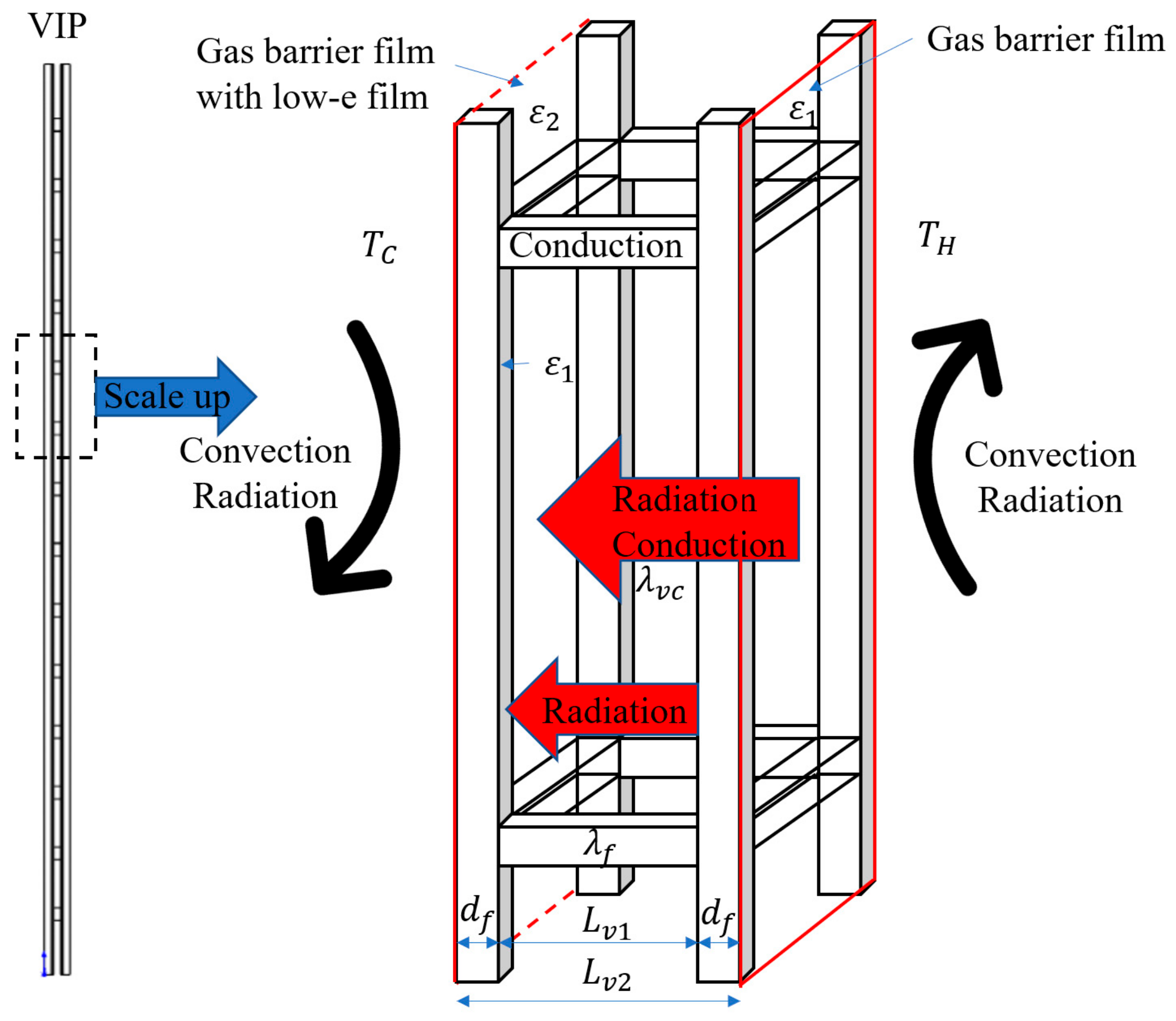
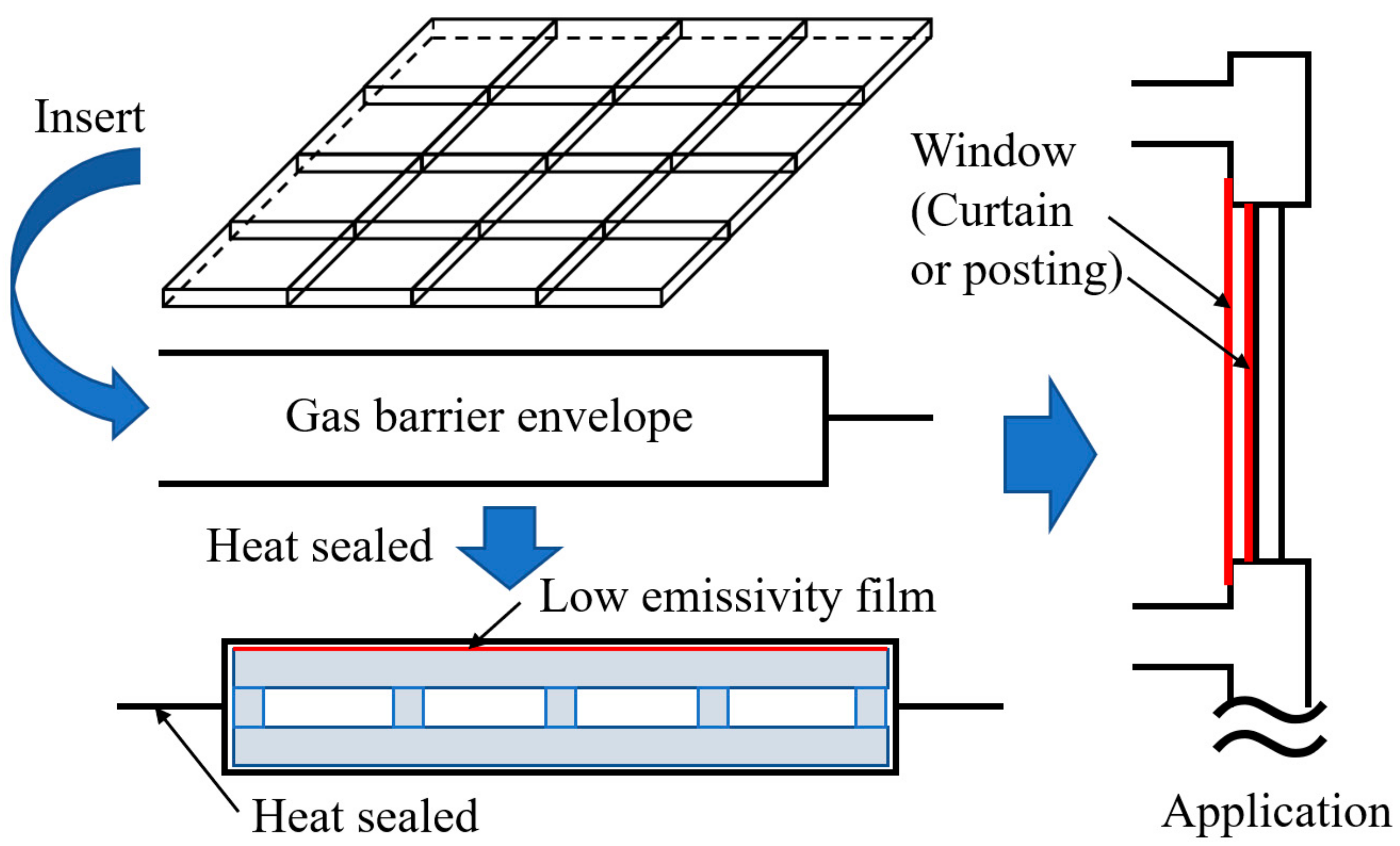
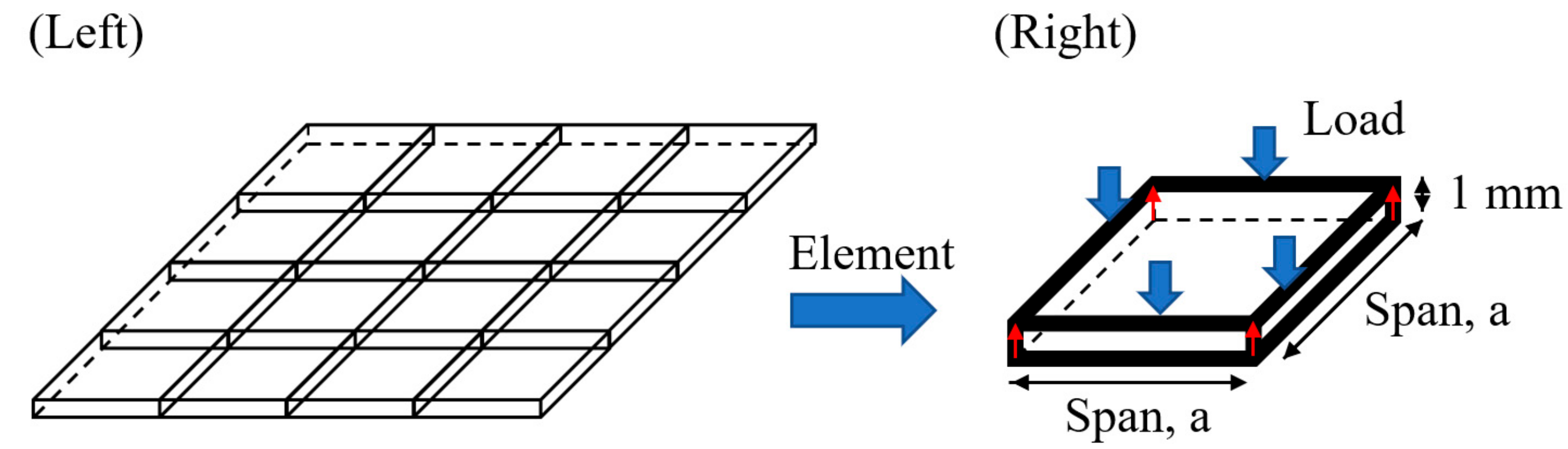
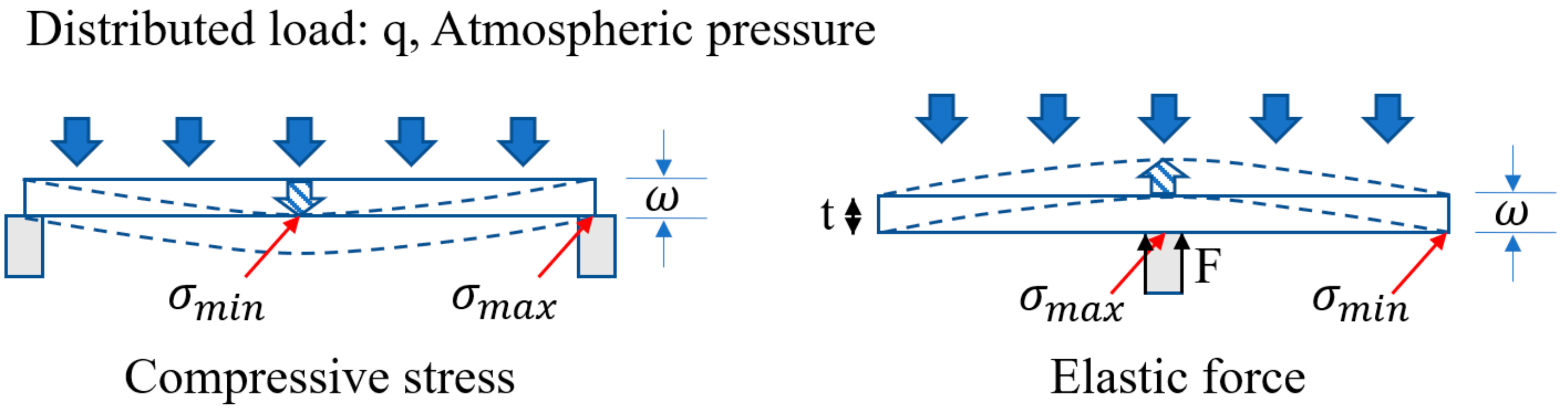
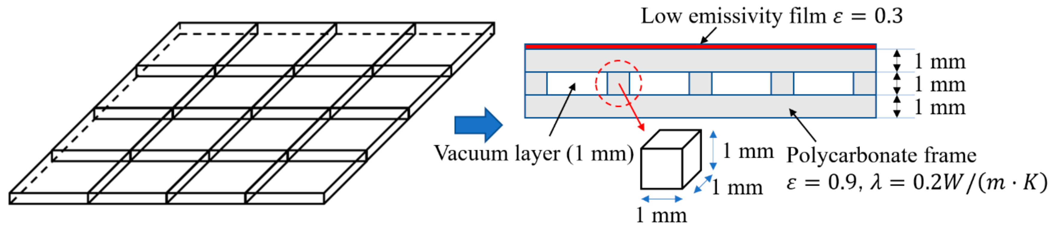
2. Core Structural Design for Frame-Structure VIP

First of all, a mechanical analysis should be applied to design the core structure of the VIP. The structural frame (the layout of the frame structure is shown in Figure 2 (left)) should be provided to hold the vacuum layer when the internal pressure is evacuated to 0.1 Pa. That means that every beam of the frame should hold up the distributed loading of atmospheric pressure in the safety margin. The schematic is shown in Figure 2 (right) [21,22]. The element analysis would have to be conducted to a structural calculation model in Figure 3, divided into calculating two possibilities.
Here, the structural analysis was performed as a simplified support beam. Usually, deflection is performed to evaluate the structural design in one dimensional view. The schematic of this calculation model shows the maximum stress should occur in the center of a beam and minimum stress in the edge. In this model, when the atmospheric pressure is loading on the surface, the compression and elastic occurs at the same time but in opposite directions. Then, we define the relationship between the deflection and span by using the equations provided below:
ω ¯ m a x = δ × P 0 × a 4 D
D = E t 3 12 ( 1 μ 2 )
For the polycarbonate frame, E is the Young’s modulus (2.32 GPa), and μ is the Poisson’s ratio (0.39). For calculations, the width of the polycarbonate frame t is 1 mm, the span a is 10 mm, the coefficient of uniform loading to a rectangular flat plate δ 1 is 0.0138, δ 2 is 0.0611, and the effect in different stresses P 0   is 1013 hPa. The maximum deflection of the frame with different spans is shown in Figure 4. However, the structural design also affects the insulation performance which is described in the next section. In order to create an appropriate design for VIP, we discussed additional models and evaluated their insulation performance. Therefore, we designed the structure by changing the width of frame from 0.5 mm to 1.5 mm, and changing the span to 5, 8, 10, 12 and 15 mm. The variation in deflection is shown in Figure 5.
A mechanical design within the safety requirements is indicated in Figure 4. We set the span of the frame to 10 mm, while considering the effects of stress and deformation, to ensure the numerical model of heat transmittance to predict the thermal insulation and specimen could be used in the experimental manufacturing. Additionally, the vacuum layer was obtained and the surface was relatively flat with a span of 10 mm. Figure 5 shows the comparison of the deflections based on different conditions. The design should also consider the insulation performance and the transparency; therefore, a frame width of 1 mm and a span of 10 mm were used.
Subsequently, to validate the structural design, we created a 3-dimensional model using the simulation software: ANSYS workbench 14.0 (ANSYS, Canonsburg, PA, USA). The distribution of deformation for the core frame that is modelled as concept in Figure 2. The fixed boundary indicates that the element analysis can be applied to a full-scale VIP, and the meshing in Figure 6 shows the calculation result is accurate due to the 257,791 nodes and 49,046 elements and the result is shown in Figure 7. The result validates the mechanical analysis in Figure 4, indicating a reasonable structural design with a sufficiently flat for application.

3. Derivation of Heat Transmittance in a VIP Element

The theoretical solution for the heat transmittance of a VIP can be derived from a frame element [23]. Figure 8 demonstrates the heat transmittance through a frame element. Usually, the “U” value is conducted to evaluate the performance of heat transmission according to this model. For an evacuated insulation design, the convection in the vacuum space can be ignored due to the well-decreased gas molecules. The details will be explained in the following section.

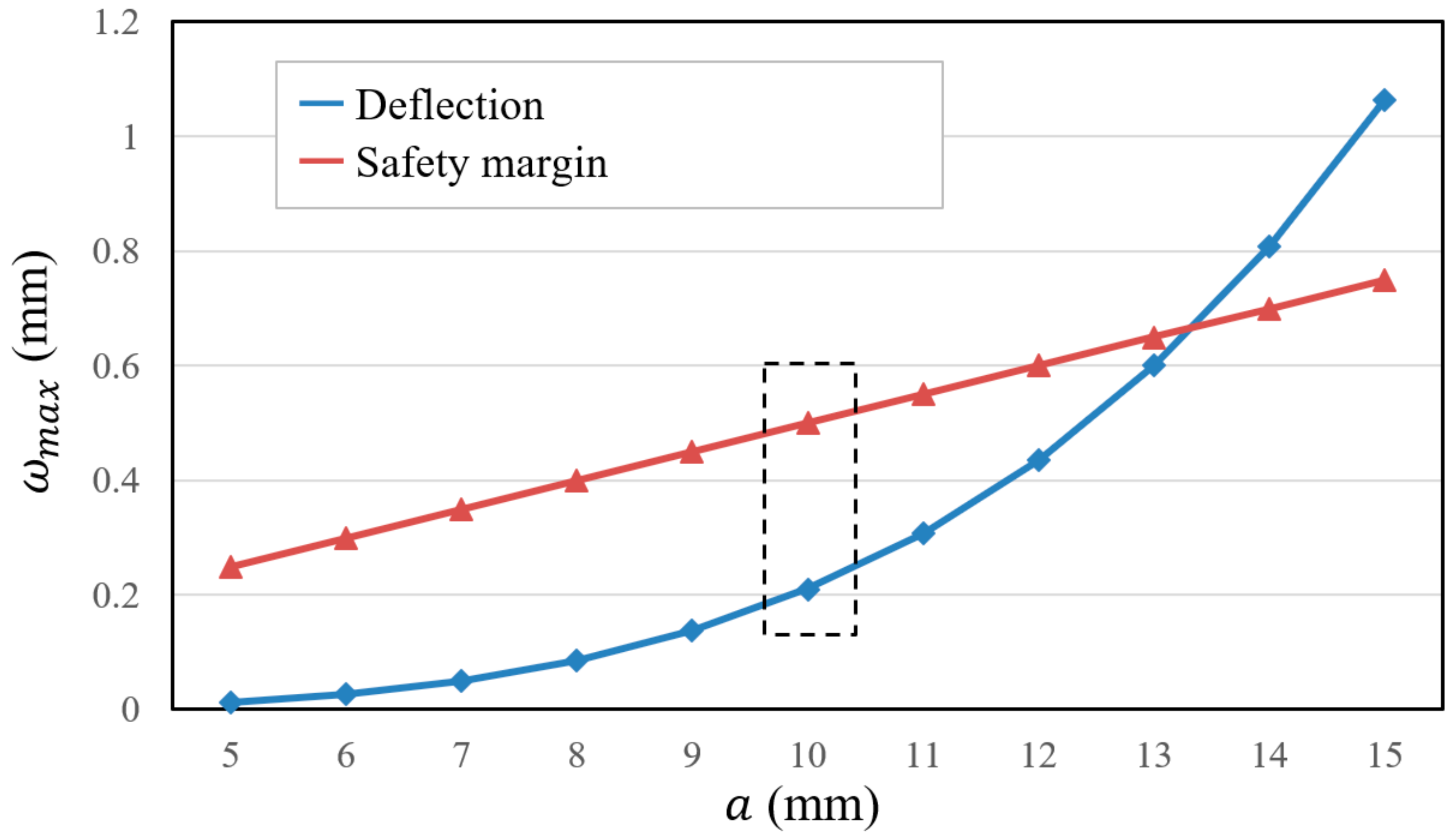
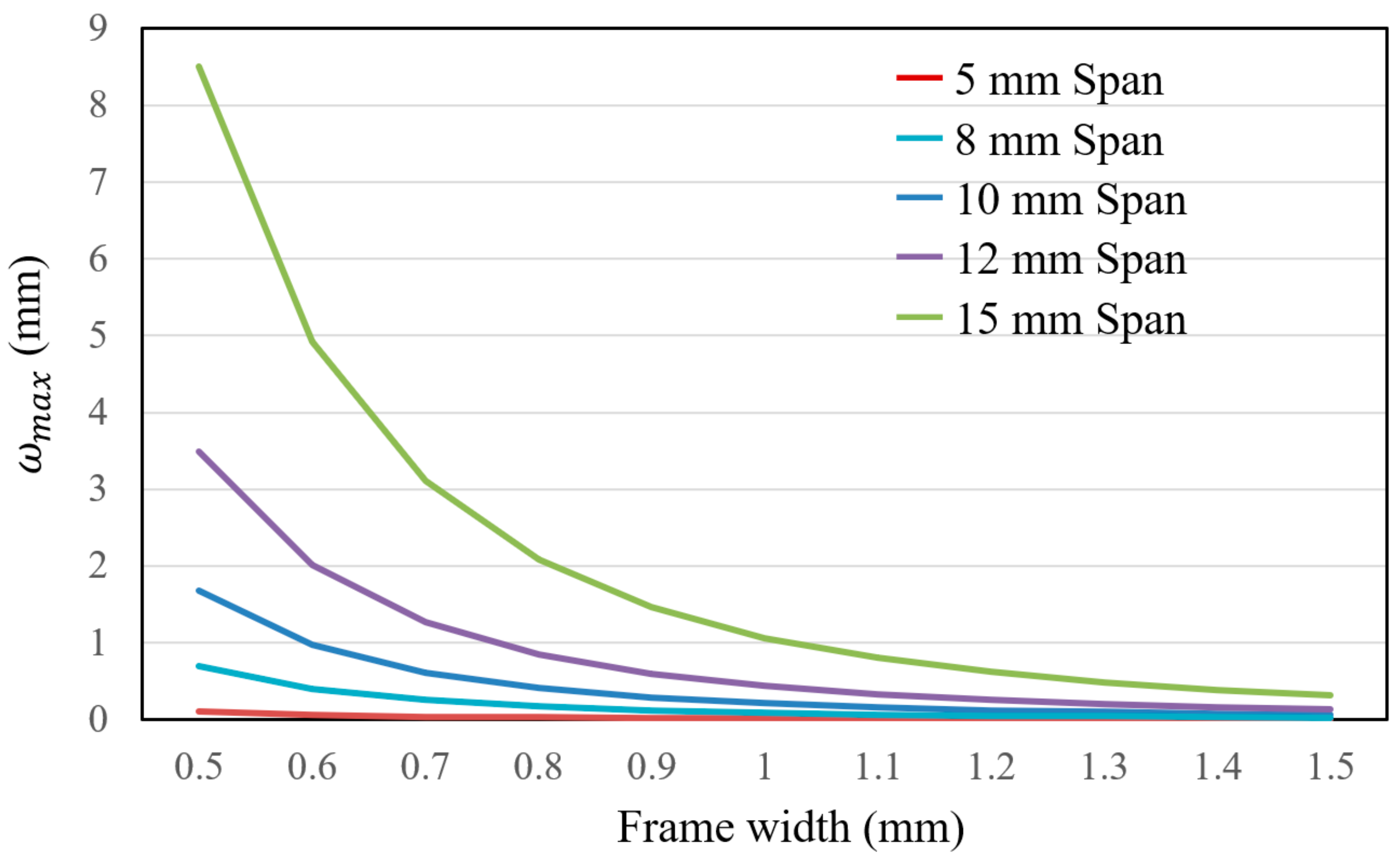
3.1. Calculation and Design of the Vacuum Layer

The reason why an evacuated product should have very good insulation performance will be discussed in this section. Heat, temperature, and the motion of molecules are all related. Temperature is a measure of the average kinetic energy of the molecules in a material. Heat is the energy transferred between materials that have different temperatures. Heat transfer is classified into various mechanisms, such as thermal conduction, thermal convection, thermal radiation, and transfer of energy by phase changes. The mass and density will be changed when the temperature distribution is inhomogeneous at a constant vacuum degree. Many studies indicate that the free convection can be converted into a pure gas heat conduction when the pressure is low enough, or reaches a typical vacuum degree. Natural convection due to gravity is usually defined by Grashof number, Grm. And most adiabatic space is confined, in order to obtain a state of pure gas heat conduction the natural convection must be prevented. Prandtl number (Prm) in the adiabatic space is all in 0.7 (air, nitrogen, and helium). Hence, Grm < 103 is considered as sufficient condition for preventing natural convection heat transfer. We can establish the equation below to evaluate as a condition how the free convection can be converted into a pure gas heat conduction:
G r m × P r m < 10 3
G r m = g β Δ T L v 3 υ 2
where g is the gravity acceleration (m/s2), β is the coefficient of expansion (1/K), and β is described by the following equation [24]:
β = 1 γ ( V T ) P b 2
where P b is the pressure ratio, such that P b = P / P 0 ; P is the vacuum pressure, (Pa); P 0 is the atmospheric pressure, (Pa); Δ T is the temperature difference between the cold and hot surface (K); L v is the thickness of the vacuum layer (m); and υ is the kinematic viscosity (m2/s).
For porous materials, feature scale is very small so that the calculated Grm is far less than 103. Therefore, natural convection heat transfer can be prevented even at normal pressure. And in porous materials, feature scale is usually in 10−4–10−8 m. For the evacuated space existed design, the feature scale is the vacuum layer L v that is far bigger than that in porous materials. Calculation indicate the natural convection heat transfer will be prevented in a relative vacuum degree.
Here, the temperature difference Δ T is 25 (K); thickness of vacuum layer L v is 10−3 m; gravity acceleration g is 9.8 (m2/s); kinematic viscosity υ is 1.323 × 10⁻⁵ (m2/s); if the assumed pressure P is 1000 Pa. We can obtain the result as Grm = 2.085 × 10² < 103. We decided a much lower design pressure to our proposal of 0.1 Pa and 1 Pa, hence, we can totally ignore the natural convection heat transfer in the numerical model for heat transmittance.
In general, the Knudsen number K n is usually defined for a gas as the ratio in Equation (6), where l is the mean free path (calculated with Equation (7)) and L v is any macroscopic dimension of interest. A high Knudsen number indicates a low pressure, and thus a slow molecular flow, whereas a low value of the Knudsen number suggests a viscous flow. Where k is the Boltzmann constant in 0.38 × 10⁻²³ (J/K); T is the temperature in 300 (K); d m is the molecular diameter in 0.37 (nm); and here P is the pressure in 0.1, 1 and 10 (Pa), respectively [25]:
K n = l L v
l = k T 2 π d 2 P
The calculated K n were 68, 6.8, and 0.68, respectively. The rarefied gas heat conduction is in the free molecular state only if the K n is less than or equal to 0.5. Then, the calculation of design the vacuum layer can be determined and the derivation will be detailed in the next section.

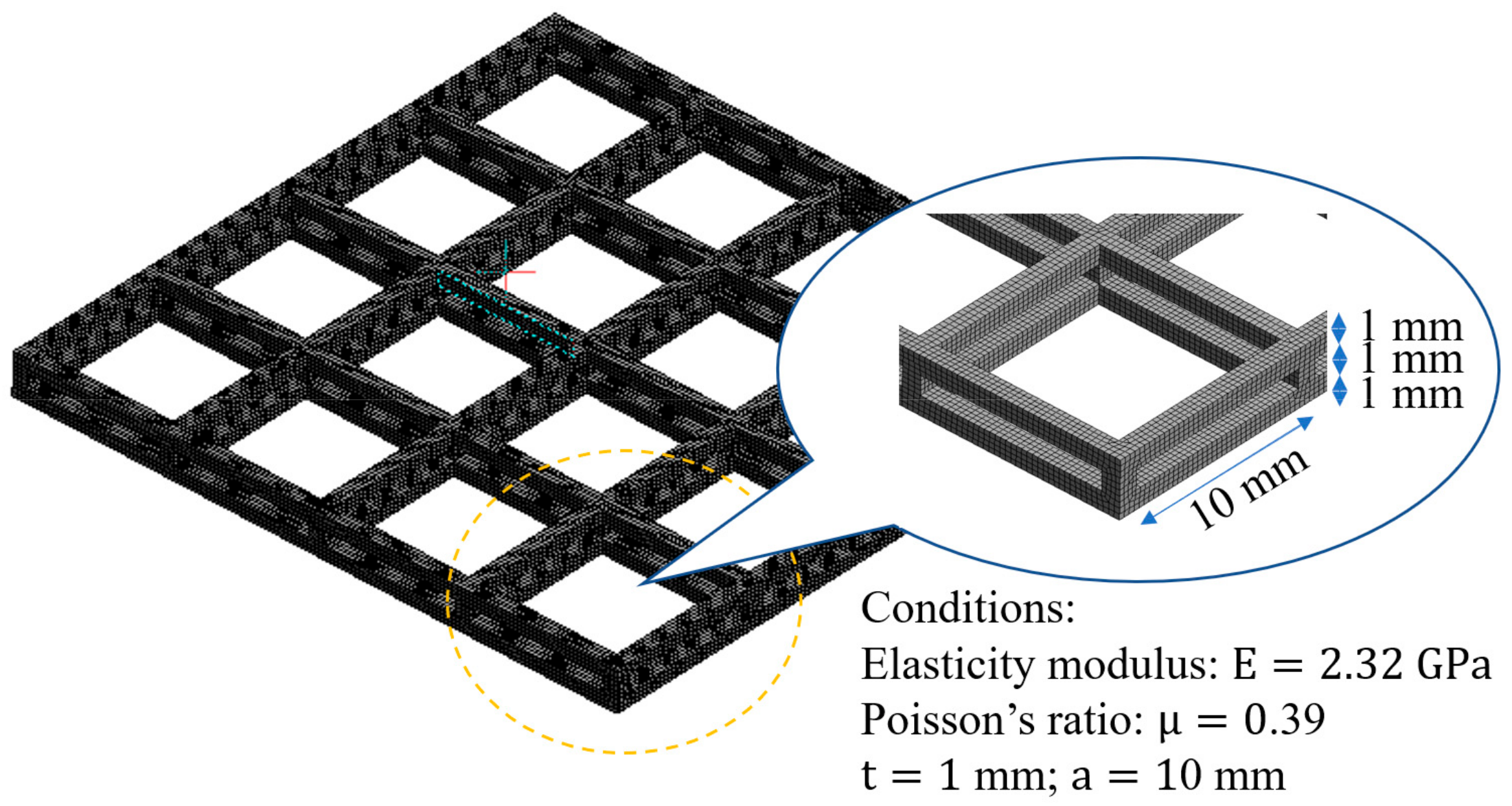
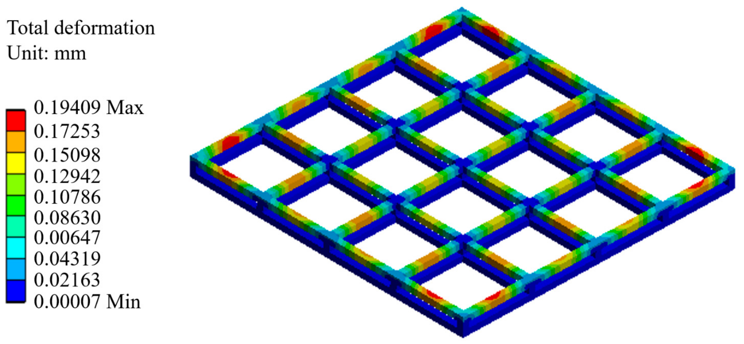
3.2. Establishment of the Numerical Model of Heat Transmittance

The “U” value is performed to evaluate a frame VIP element and defined by the following equations [24,25,26]:
U = 1 R C + R V + R H
where U is the overall heat transfer coefficient of the VIP (W/(m2·K)); R C is thermal resistance of low temperature surface ((m2·K)/W); R H is the thermal resistances of high temperature surface ((m2·K)/W). R V is the thermal resistance of evacuated space with frame ((m2·K)/W), calculation of R V can be categorized into conductive heat transfer and radiant heat transfer, defined as Equations (9)–(13), respectively. The R V is determined by the heat transfer model:
2 T x 2 + 2 T y 2 + 2 T z 2 = 0
Heat conduction in evacuated space can be calculated by the above equation, and the heat transfer in the frame is considered the only conductive heat transfer. The equation is the same as the equation above. Here, the thermal conductivity of the evacuated space λ v is a constant, calculated by the equation below:
λ v = 18.2 L γ + 1 γ 1 β 0 P M T
1 T 2 T 1 + T 2
where γ is the specific heat ratio, defined as Cp/Cv, and β is the accommodation coefficient. L in Equation (10) is categorized into with the frame and without the frame defined as L v 1 and L v 2 shown in Figure 8.
The radiant heat transfer in an evacuated space is defined by the equations below:
h v r = σ T m 3 ( ε 1 ε 2 ) φ 1 , 2
where σ is the Stefan-Boltzmann constant (5.67 × 10⁻⁸ W/(m2K4)), ε1 and ε2 are the optimized emissivities of the gas barrier film and low-e film at mean temperature T m (K), and φ 1 , 2 is the angle factor between the two surfaces of the VIP that can be calculated by the following equation:
φ 1 , 2 = 1 A 2 A 1 A 2 c o s θ 1 c o s θ 2 π r 2 δ 12 d A 1 d A 2
where δ 12 is determined by the visibility of d A 2 to d A 1 , δ 12 = 1 if d A 2 is visible to d A 1 and is 0 otherwise.

4. Validation of the Numerical Model with Experimental Results

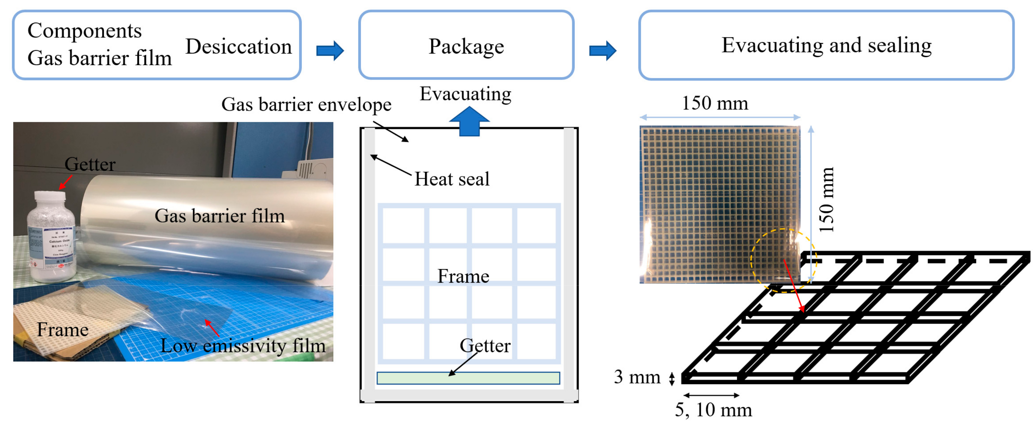
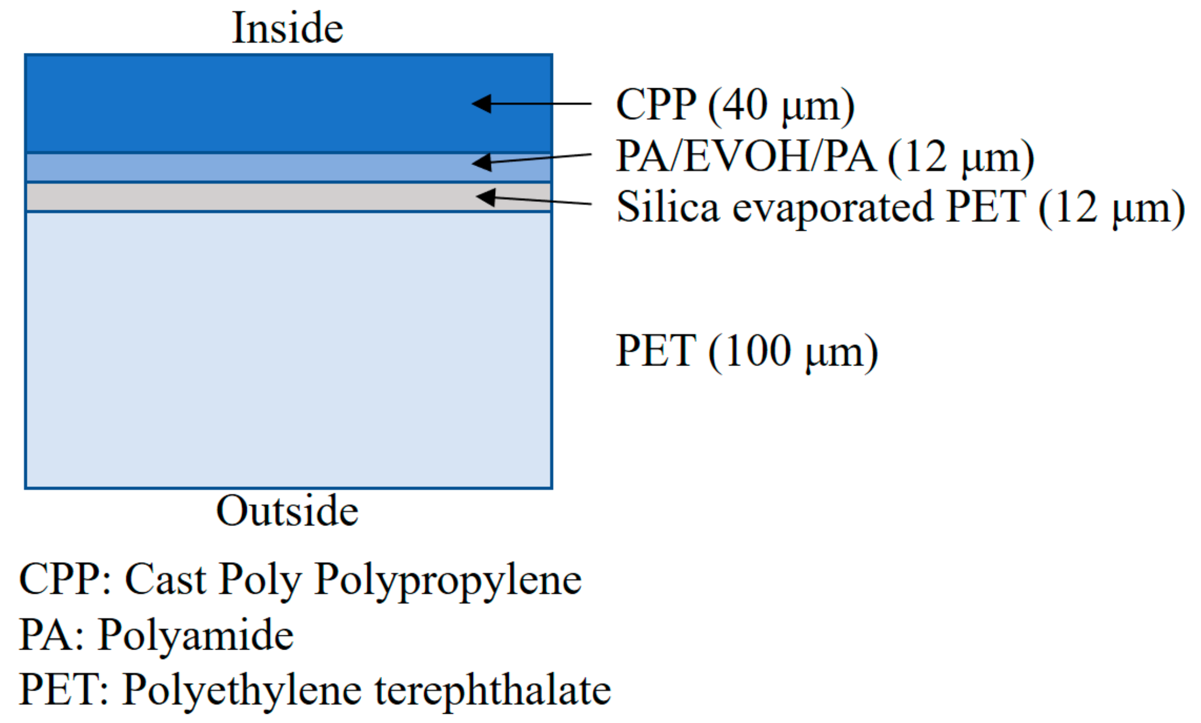
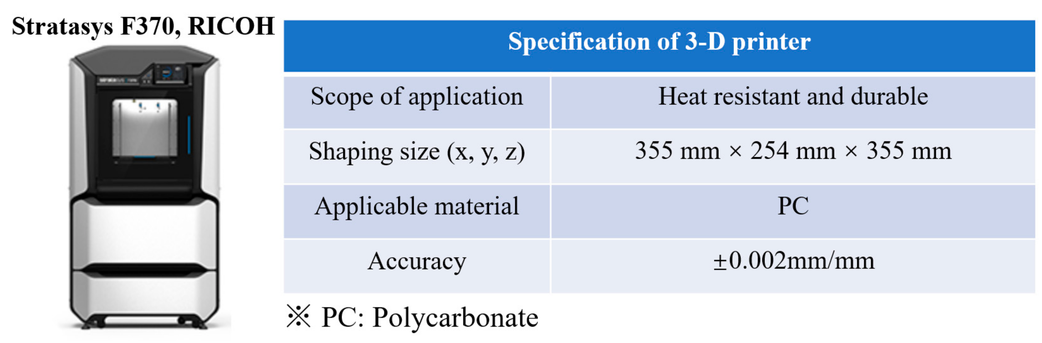
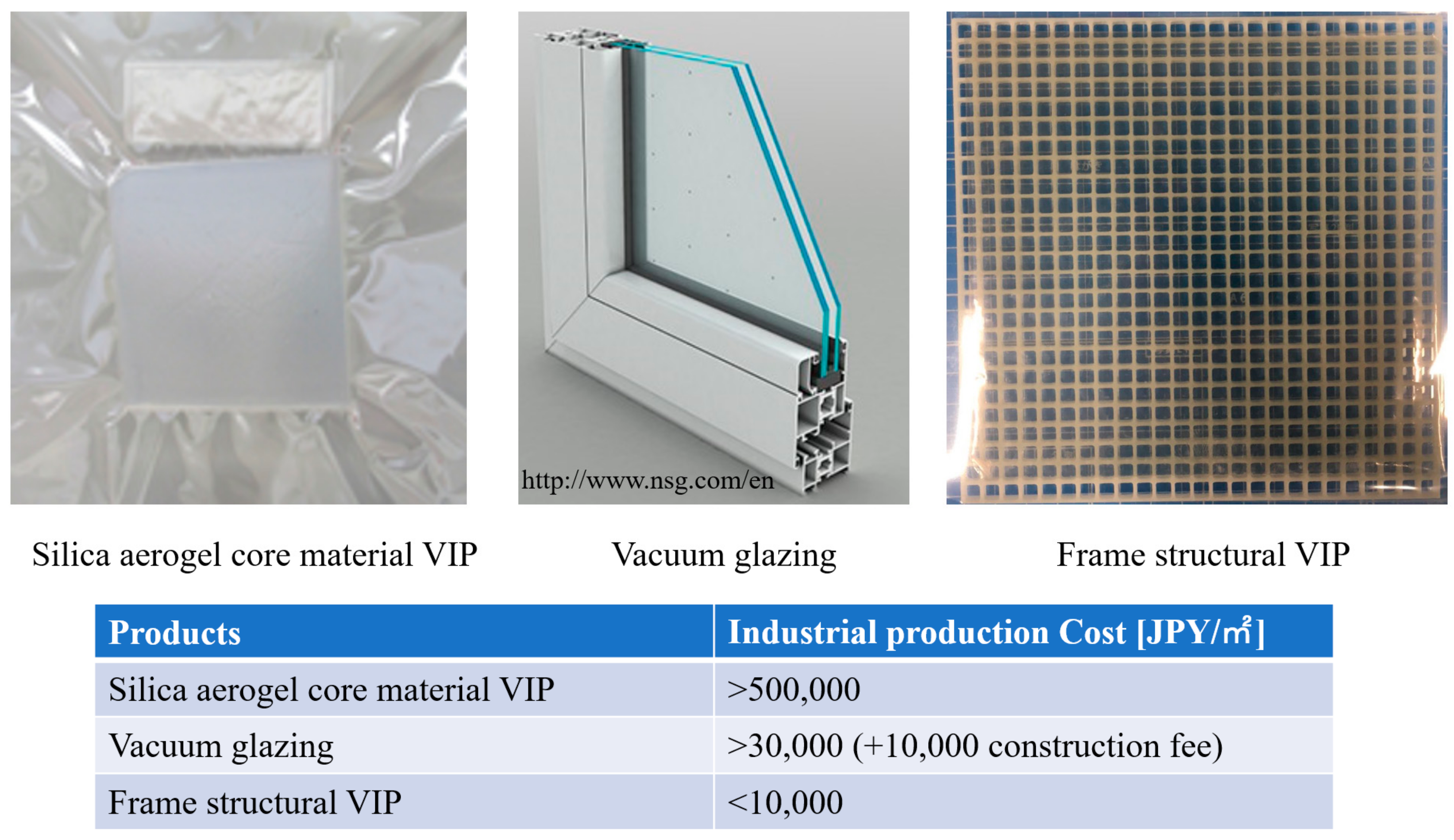
4.1. Specimen Production and its Cost Performance Evaluation

The test specimen was prepared for the experimental validation, and the production process is illustrated in Figure 9. A 3-D printer was used to produce the test specimen (specifications of the 3-D printer are provided in Figure 10) and a low-emissivity film covered the frame surface, then the assembled components were coating by a transparent gas barrier envelope. To improve the degradation resistance, calcium oxide getter was sealed together with the frame. For the evacuated products, being airtight is critical. The components indicate a good airtight to the gas barrier film are depicted in Figure 11. To ensure the affordability of retrofitting the insulation of existing buildings, a product must have good cost-performance; Figure 12 compares the industrial manufacturing cost of these three insulation products. The developed frame-structure VIP is compared with two other transparent evacuated insulation products: a vacuum glazing and a silica aerogel core material VIP. Usually, silica aerogel fills a double plate unit as a double layer of glass and is removed to create an evacuated insulation product. In this study, the silica aerogel core material VIP was used as the experimental batch and was not a commercial product. Silica aerogel is very expensive. The cost of vacuum glazing can be obtained from the website provided in Figure 12.

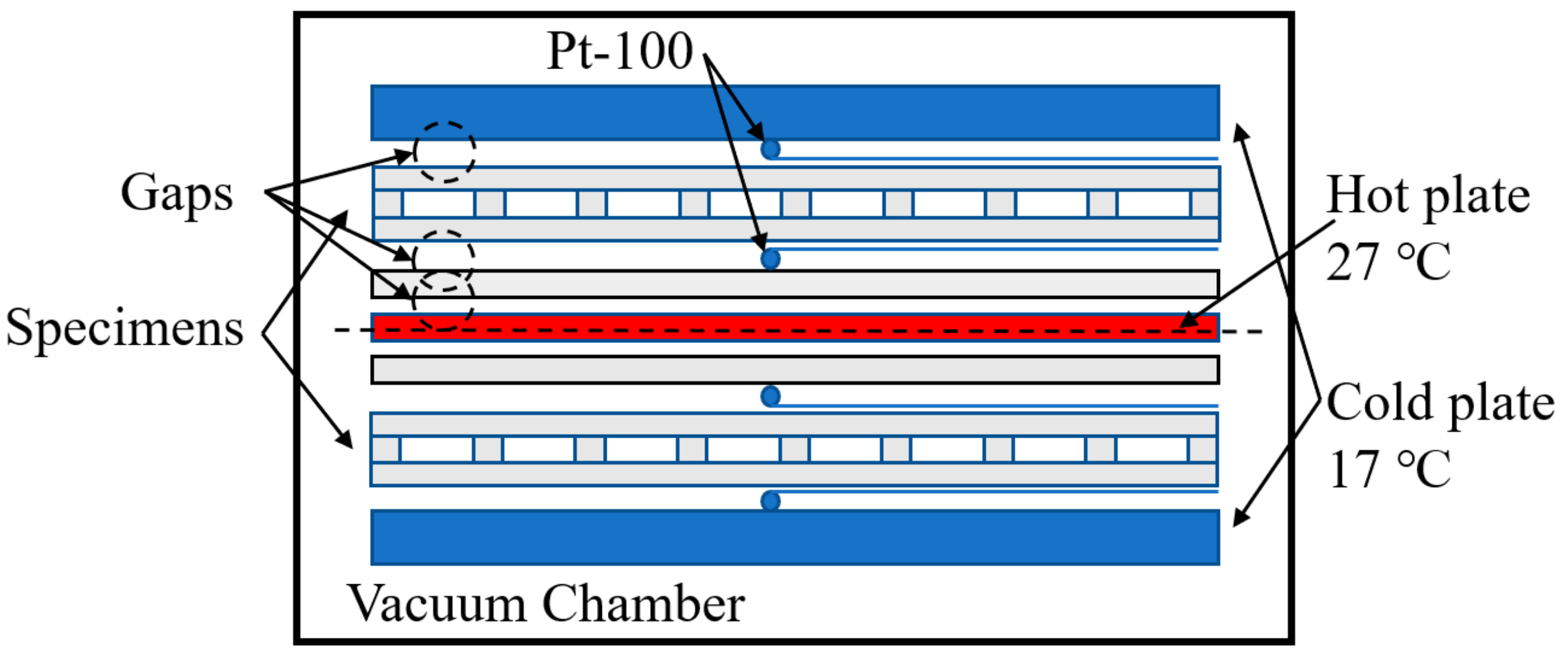
4.2. Guarded Hot Plate Apparatus Framework

The guarded hot plate apparatus (GHP) is the main method used to measure the thermal conductivity of homogeneous thermal insulation. The apparatus can measure a wide variety of specimens, from flat-slab to porous, and a wide range of environmental conditions including different temperatures and pressures. The VIP specimens are placed between the heating and cooling plates and guarded in an airtight chamber. The cold plates are heated such that a well-defined, user-selectable temperature difference Δ T (°C) is established between the hot and the cold plates (over the sample thickness). The power input Q (W) in the hot plate with area A (m2) is then measured as soon as thermal equilibrium is reached. Using the measured sample thicknesses, temperatures and power inputs, the thermal conductivity can be determined from the steady-state heat transfer equation. Furthermore, this apparatus can provide an evacuated space which is very efficient in evaluating the insulation performance in a stable vacuum environment. Until the stable heat flow and vacuum degree is reached, the thermal conductivity of the specimen (λ) is derived by the following equation:
λ = Q / 2 A Δ T / d
Figure 13 shows the schematic diagram of the GHP apparatus. The temperature sensor Pt-100 was used to measure the thermal conductivity with an accuracy of ±|0.15 + 0.002(t)|. The hot plate has 10 temperature sensors in the hot plate and five in the cold plate which are set in different directions.

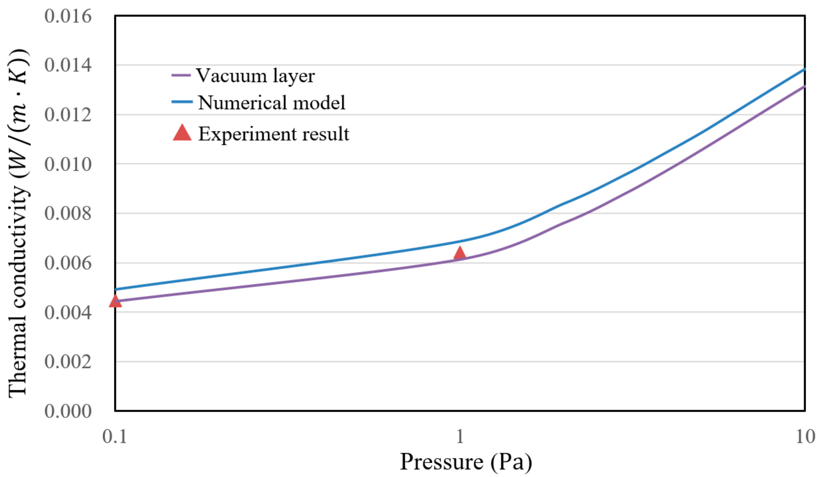
4.3. VIP Specimen Using GHP Method, Calculation Conditions, and Results

Figure 14 shows the conceptual diagram of the test specimen and also a model for case study. From Section 3.1, we realize that when the pressure is decreased below 1 Pa, good insulation performance can be achieved because convection can be ignored in a free molecular state. Therefore, the pressure inside the chamber of the GHP apparatus can be set to 0.1 Pa and 1 Pa, which is good and typical to evaluate the evacuated insulation techniques. Figure 15 compares the thermal conductivities obtained from the calculation and the experimental result based on the pressure.
The calculation conditions and designable factors of the VIP are also depicted in Figure 14. In the case studies, the thermal conductivity of the polycarbonate frame was 0.2 W/(m·K), and the thermal emissivities of the polycarbonate frame, gas barrier envelope and low-e film were 0.9, 0.9 and 0.3, respectively. In the calculation, the temperature difference was 25 °C.
In this experimental apparatus, gaps exist in the evacuated chamber and these are pointed out in Figure 13. Hence, the experimental result can be optimized using Equation (15) to eliminate the influence of the gaps:
R VIP = R m R V a 1 R v a 2 R v a 3
where R v a = R v c + R v r and R v c can be calculated with Equation (12). The equation indicates that the thermal resistance in evacuated space is not related to the thickness, hence, the thermal resistance of the gaps is the same in the value. R v r is calculated using Equations (15) and (16), and the given thermal emissivity is 0.9. The experimental results and their optimized results by Equation (18) are shown in Table 1. The calculation and experimental results are compared and illustrated in Figure 15:
λ VIP = L v / R VIP
In Figure 15, the calculation results of the numerical model are in agreement with the experimental results. Predicting the insulation performance in this model is valuable. The frame-structure VIP has very good insulation performance for retrofitting the insulation in existing buildings. In addition, the thermal conductivity of the vacuum layer without a frame demonstrated the excellent performance of the evacuated space. Then, the design should be improved by reducing the thermal bridge of the frame structure.

5. Case Studies for Vacuum Layer Type Translucent VIP

5.1. Calculation Conditions

Here, the frame-structure VIP is discussed further and its insulation performance is evaluated through different design proposals. With considering the stability of the frame, we determined the VIP specifications, so that the thermal conductivity of the frame was 0.2 W/(m·K), and the width and span of the frame were controlled. The other conditions are presented in Table 2.

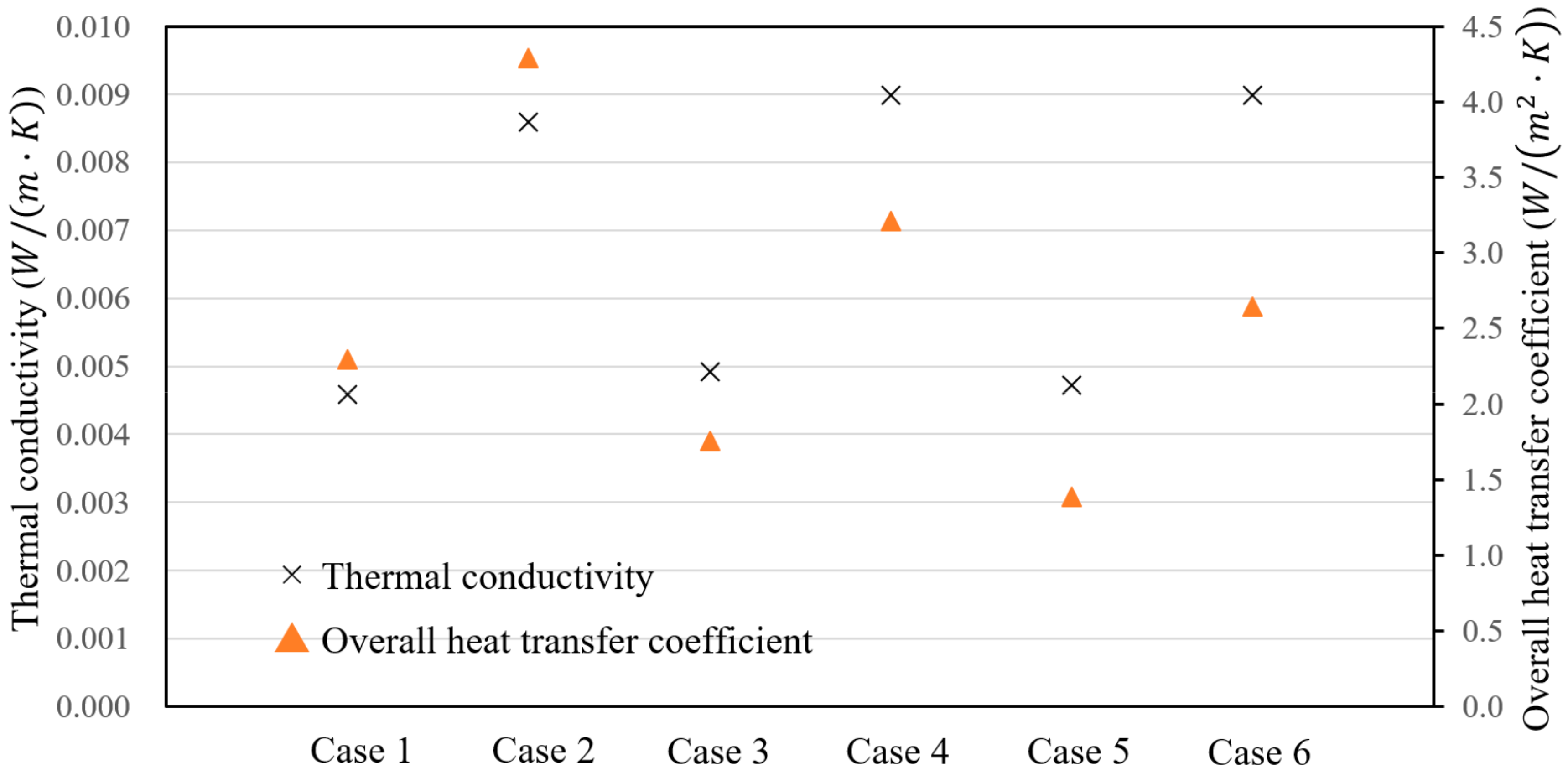
5.2. Results and Discussion

A comparison results from the case studies is provided in Figure 16. The calculation result of thermal conductivity in Cases 2, 4, and 6 were higher than those for Cases 1, 3, and 5 due to the higher thermal emissivity. Case 1 and Case 2, due to the higher conduction caused by the high area ratio, and a dense frame, are not suitable in terms of transparency. Case 5 and Case 6 reduce the frame area; however, perfectly maintaining a vacuum layer was difficult. Case 3 appears to be the most appropriate design in terms of structural safety, insulation performance, and transparency. The low emissivity is only applied to one side to improve the insulation performance while maintain affordability. The small width of the frame is also possible if required.
Figure 16 indicates that Case 3 and Case 5 should be suitable designs as the lower heat transfer coefficient would contribute to retrofitting the windows of existing buildings. However, the thickness of the vacuum layer is only 1 mm; a wider frame web span cannot sufficiently achieve a vacuum layer due to the excessive compression of the gas barrier envelope. To summarize, Case 3 is the most appropriate for producing a vacuum layer to achieve good insulation performance, and to reduce the material area in the vacuum space to resist degradation.

6. Conclusions

We have proposed a frame-structure, thin, and translucent VIP with a low industrial manufacturing cost that is easy to apply. A structural calculation model was used to evaluate whether the frame could structurally maintain an evacuated space. The results indicated that the evacuated layer could be maintained under the design value of the span was 10 mm and width of frame was 1 mm. Heat transfer models were used to predict the insulation performance of the VIPs by analyzing the heat transfer in the frame element. The thermal conductivities of the VIPs were calculated by varying the calculation conditions of the different design conditions. The insulation performance was evaluated for future applications because the “U” value was less than 2.0 W/(m·K). The calculation results were in agreement with the experimental results. Furthermore, to obtain better insulation performance, using trusses may strengthen the frame structure, and expanding the frame web may reduce the heat conduction.

Acknowledgments

This study was financially supported by the Grants-in-Aid for Scientific Research of the JSPS (Research representative: Takao Katsura, Subject number: 15H05538). Hokkaido Electric Power Co., Inc., Mitsubishi Chemical Corporation, TEIJIN FRONTIER CO., LTD., ULVAC, Inc., and Miyoshi Vacuum Packing for their assistance in the VIP test production.

Author Contributions

Zhang Yang and Takao Katsura proposed the prediction model and conceived the experiments; Makoto Nakamura and Masahiro Aihara assist performed the experiments; Zhang Yang and Takao Katsura analyzed the data; Zhang Yang wrote the paper.

Conflicts of Interest

The authors declare no conflict of interest.

References

  1. Butler, D. Architecture: Architects of a low-energy future. Nature 2008, 452, 520–523. [Google Scholar] [CrossRef] [PubMed]
  2. Saari, A.; Kalamees, T.; Jokisalo, J.; Michelsson, R.; Alanne, K.; Kurnitski, J. Financial viability of energy-efficiency measures in a new detached house design in Finland. Appl. Energy 2012, 92, 76–83. [Google Scholar] [CrossRef]
  3. Lim, T.; Seok, J.; Kim, D.D. A Comparative Study of Energy Performance of Fumed Silica Vacuum Insulation Panels in an Apartment Building. Energies 2017, 10, 2000. [Google Scholar] [CrossRef]
  4. Capozzoli, A.; Fantucci, S.; Favoino, F.; Perino, M. Vacuum Insulation Panels: Analysis of the Thermal Performance of Both Single Panel and Multilayer Boards. Energies 2015, 8, 2528–2547. [Google Scholar] [CrossRef]
  5. Park, S.; Choi, B.-H.; Lim, J.-H.; Song, S.-Y. Evaluation of Mechanically and Adhesively Fixed External Insulation Systems Using Vacuum Insulation Panels for High-Rise Apartment Buildings. Energies 2014, 7, 5764–5786. [Google Scholar] [CrossRef]
  6. Collins, R.E.; Turner, G.M.; Fisher-Cripps, A.C. Vacuum Glazing—A New Component for Insulating Windows. Build. Environ. 1995, 30, 459–492. [Google Scholar] [CrossRef]
  7. Fisher-Cripps, A.C.; Collins, R.E.; Turner, G.M.; Bezzel, E. Stress and Fracture Probability in Evacuated Glazing. Build. Environ. 1995, 30, 41–59. [Google Scholar] [CrossRef]
  8. Garrison, J.D.; Collins, R.E. Manufacture and cost of Vacuum Glazing. Sol. Energy 1995, 55, 151–161. [Google Scholar] [CrossRef]
  9. Turner, G.M.; Collins, R.E. Measurement of Heat flow through Vacuum Glazing at elevated Temperature. Int. J. Heat Mass Transf. 1997, 40, 1437–1446. [Google Scholar] [CrossRef]
  10. Lenzen, M.; Collins, R.E. Long-term Field Tests of Vacuum Glazing. Sol. Energy 1997, 61, 11–15. [Google Scholar] [CrossRef]
  11. Collins, R.E.; Simko, T.M. Current Status of the Science and Technology of Vacuum Glazing. Sol. Energy 1998, 62, 189–213. [Google Scholar] [CrossRef]
  12. Simko, T.M.; Fisher-Cripps, A.C.; Collins, R.E. Temperature-induced in Vacuum Glazing Modelling and Experimental Validation. Sol. Energy 1998, 63, 1–21. [Google Scholar] [CrossRef]
  13. Nippon Sheet Glass Co. Available online: http://www.nsg-spacia.co.jp (accessed on 18 May 2005).
  14. Griffiths, P.W.; Di Leo, M.; Cartwright, P.; Eames, P.C.; Yianoulis, P.; Leftheriotis, G.; Norton, B. Fabrication of evacuated glazing at low temperature. Sol. Energy 1998, 63, 243–249. [Google Scholar] [CrossRef]
  15. Wittwer, V. Private Communication; Fraunhofer Institute for Solar Energy Systems: Freiburg, Germany, 2005. [Google Scholar]
  16. Baechli, E. Thermally Insulating Construction and/or Lighting Element. Eur. Pat. No. 0247098B1, 25 March 1992. [Google Scholar]
  17. Baechli, E. Gastight Edge Seal. Eur. Pat. No. 0434802B1, 23 March 1994. [Google Scholar]
  18. Sager-Hintermann, K.; Baechli, E. Method and Equipment for Making Heat-Insulating Construction and/or Lighting Elements. Eur. Pat. No. 1221526, 10 July 2002. [Google Scholar]
  19. Yang, Z.; Katsura, T.; Aihara, M.; Nakamura, M.; Nagano, K. Development of Numerical Heat Transfer and the Structural Model to Design Slim and Translucent Vacuum Layer Type Insulation Panels to Retrofitting Insulation in Existing Buildings. Energies 2017, 10, 2108. [Google Scholar] [CrossRef]
  20. Collins, R.E.; Davis, C.A.; Dey, C.J.; Robinson, S.J.; Tang, J.Z.; Turner, G.M. Measurement of local heat flow in flat evacuated glazing. Int. J. Heat Mass Transf. 1993, 36, 2553–2563. [Google Scholar] [CrossRef]
  21. Timoshenko, S.; Woinowsky-Krieger, S. Theory of Plate and Shell; McGraw-Hill Book Company: Columbus, OH, USA, 1959; pp. 106–108. [Google Scholar]
  22. Young, W.C.; Budynas, R.G. Roark’s Formulas for Stress and Strain, 7th ed.; McGraw-Hill Professional: New York, NY, USA, 2001; pp. 508–509. [Google Scholar]
  23. Gan, G. Thermal transmittance of multiple glazing: Computational fluid dynamics prediction. Appl. Therm. Eng. 2001, 21, 1583–1592. [Google Scholar] [CrossRef]
  24. Springer, G.S. Heat Transfer in Rare Field Gases. Adv. Heat Transf. 1971, 7, 163–218. [Google Scholar]
  25. Jousten, K.; Jitschin, W.; Sharipov, F.; Pumps, P.D.; Dirscherl, J.; Lachenmann, R.; Jünemann, A.; Friedrichsen, I.; Lippelt, E.; Kossek, B.; et al. Handbook of Vacuum Technology, 1st ed.; Jousten, K., Ed.; Wiley: Weinheim, Germany, 2008; pp. 51–81. [Google Scholar]
  26. Eckert, E.R.G.; Drake, R.M. Heat and Mass Transfer, 2nd Revised ed.; McGraw-Hill Inc.: Columbus, OH, USA, 1959. [Google Scholar]
Figure 1. Conceptual diagram of the application of vacuum insulation panels (VIP) to buildings.
Energies 11 00298 g001
Figure 2. Element mechanical analysis for a frame-structure VIP: (left) the layout of the frame structure; (right) the schematic.
Energies 11 00298 g002
Figure 3. Schematic diagram of the structural model.
Energies 11 00298 g003
Figure 4. The maximum deflection of the frame with different spans.
Energies 11 00298 g004
Figure 5. Comparison of deflections under different conditions.
Energies 11 00298 g005
Figure 6. Three-dimensional meshing stage in finite element model.
Energies 11 00298 g006
Figure 7. Distribution of deflection on frame (3-dimensional).
Energies 11 00298 g007
Figure 8. Schematic of heat transfer through a frame element.
Energies 11 00298 g008
Figure 9. Trial production of the VIP specimens.
Energies 11 00298 g009
Figure 10. 3-D printer specifications.
Energies 11 00298 g010
Figure 11. Structures of the gas barrier film.
Energies 11 00298 g011
Figure 12. Industrial manufacture cost of transparent evacuated insulation products.
Energies 11 00298 g012
Figure 13. Schematic of the guarded hot plate apparatus.
Energies 11 00298 g013
Figure 14. Concept diagram of the VIP specimen and model for the case study.
Energies 11 00298 g014
Figure 15. Comparison of the simulation and experimental results.
Energies 11 00298 g015
Figure 16. Comparison of the calculated results for the case studies.
Energies 11 00298 g016
Table 1. Guarded hot plate (GHP) experimental results.
Pressure (Pa)Experimental Thermal Conductivity
λm (mW/(m·K))
Experimental Thermal Resistance
Rm ((m2·K)/W)
Thermal Resistance of Gaps
Rva ((m2·K)/W)
Thermal Resistance of VIP (Optimized)
RVIP ((m2·K)/W)
Thermal Conductivity of VIP (Optimized)
λVIP (mW/(m·K))
0.12.72.100.211.274.2
13.41.570.170.886.2
Table 2. Calculation conditions.
ConditionsLv (m)P (Pa)Frame Width (mm)Span (mm)ε1ε2Thickness (mm)
Case 11.0 × 10–30.10.550.30.92
Case 210.550.90.92
Case 30.10.9100.30.92.8
Case 410.9100.30.92.8
Case 50.11.2150.90.93.4
Case 611.2150.30.93.4

