A Novel Thermal Module with 3-D Configuration Pulsating Heat Pipe for High-Flux Applications


Abstract
1. Introduction
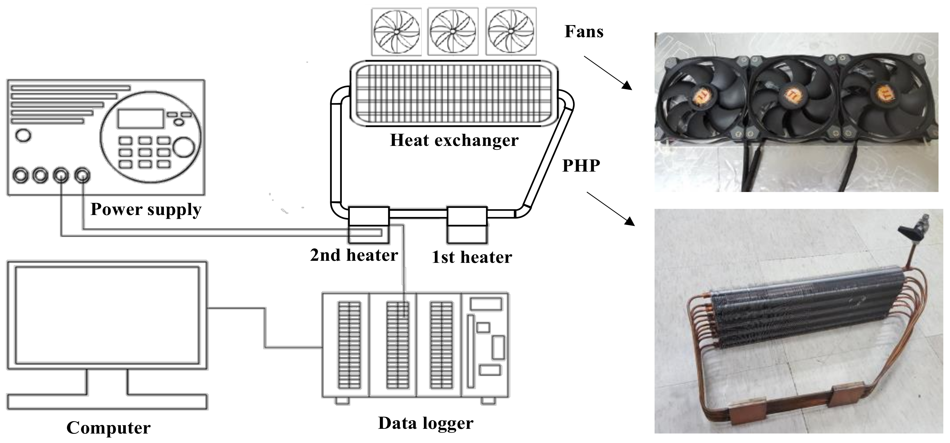
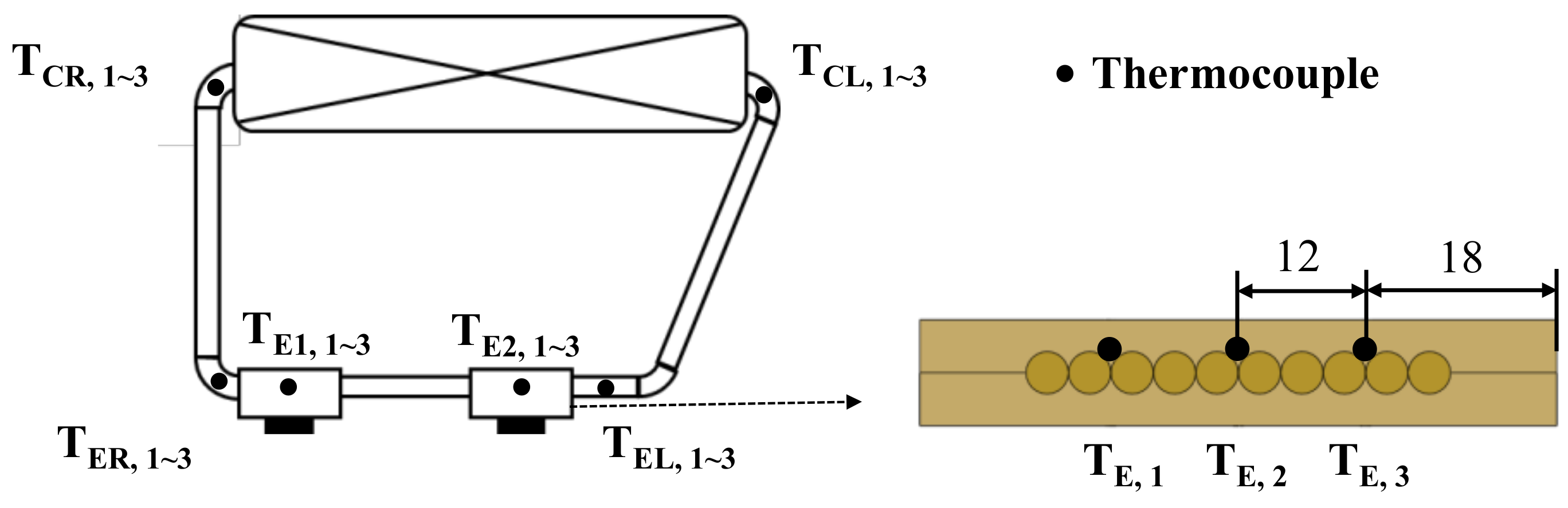
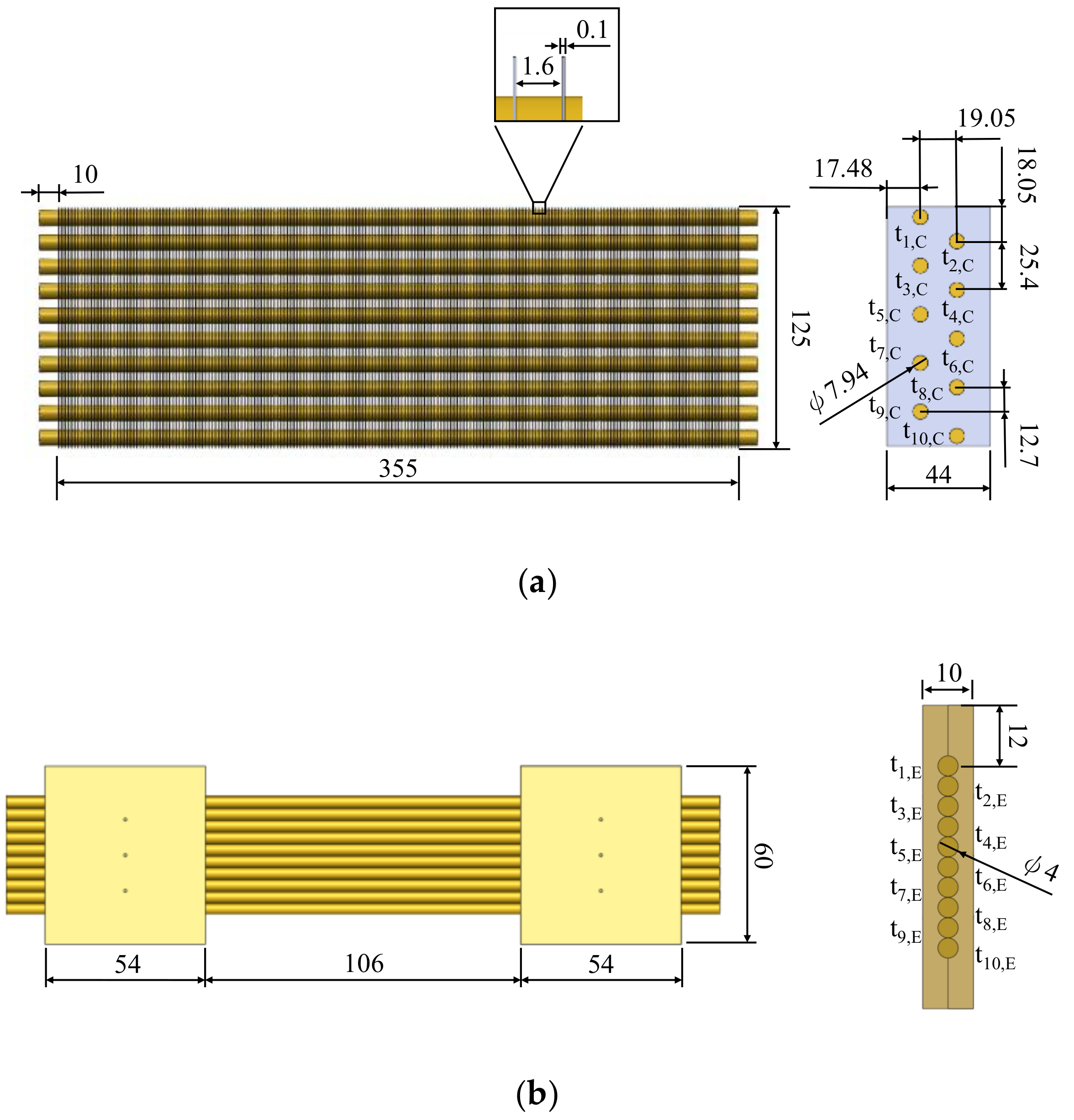
2. Experimental Apparatus
- Face area: 355 (W) × 125 (H) mm2.
- Transverse tube and longitudinal tube pitch: 25.4 mm (Pt) and 19.05 mm (Pl), respectively.
- Fin pitch and fin thickness: 1.6 mm, and 0.1 mm, respectively.
- The number of tube rows: 2, with 5 rows in each tube row.
- Nominal outer tube diameter and inner diameter: 7.94 mm and 7.5 mm, respectively.
3. Results and Discussion
4. Conclusions
Author Contributions
Funding
Acknowledgments
Conflicts of Interest
Nomenclature
| A | area, (m2) |
| cp | specific heat of water, (J/kg·K) |
| D | diameter, (m) |
| H | height, (m) |
| P | pressure, (Pa) |
| Pl | longitudinal pitch, (m) |
| Pt | transverse pitch, (m) |
| R | thermal resistance, (K/W) |
| T | temperature, (K) |
| W | width, (m) |
| Subscript | |
| amb | ambient |
| avg | average |
| BC | bend tube at condenser |
| BE | bend tube at evaporator |
| CL | left side of condenser |
| CR | right side of condenser |
| C | condenser |
| E | evaporator |
| EL | left side of evaporator |
| ER | right side of evaporator |
| SC | straight tube near condenser |
| SE | straight tube near evaporator |
References
- Chan, C.; Siqueiros, E.; Ling-Chin, J.; Royapoor, M.; Roskilly, A. Heat utilisation technologies: A critical review of heat pipes. Renew. Sustain. Energy Rev. 2015, 50, 615–627. [Google Scholar] [CrossRef]
- Chen, X.; Ye, H.; Fan, X.; Ren, T.; Zhang, G. A review of small heat pipes for electronics. Appl. Therm. Eng. 2016, 96, 1–17. [Google Scholar] [CrossRef]
- Faghri, A. Heat pipes: review, opportunities and challenges. Front. Heat Pipes (FHP) 2014, 5. [Google Scholar] [CrossRef]
- Nazari, M.A.; Ahmadi, M.H.; Ghasempour, R.; Shafii, M.B.; Mahian, O.; Kalogirou, S.; Wongwises, S. A review on pulsating heat pipes: from solar to cryogenic applications. Appl. Energy 2018, 222, 475–484. [Google Scholar] [CrossRef]
- Goshayeshi, H.; Goodarzi, M.; Dahari, M. Effect of magnetic field on the heat transfer rate of kerosene/Fe2O3 nanofluid in a copper oscillating heat pipe. Exp. Therm. Fluid Sci. 2015, 68, 663–668. [Google Scholar] [CrossRef]
- Chien, K.H.; Lin, Y.T.; Chen, Y.R.; Yang, K.S.; Wang, C.C. A novel design of pulsating heat pipe with fewer turns applicable to all orientations. Int. J. Heat Mass Transf. 2012, 55, 5722–5728. [Google Scholar] [CrossRef]
- Yang, K.-S.; Cheng, Y.-C.; Jeng, M.-S.; Chien, K.-H.; Shyu, J.-C. An Experimental Investigation of Micro Pulsating Heat Pipes. Micromachines 2014, 5, 385–395. [Google Scholar] [CrossRef]
- Yang, K.-S.; Cheng, Y.-C.; Liu, M.-C.; Shyu, J.-C. Micro pulsating heat pipes with alternate microchannel widths. Appl. Therm. Eng. 2015, 83, 131–138. [Google Scholar] [CrossRef]
- Tseng, C.-Y.; Yang, K.-S.; Chien, K.-H.; Jeng, M.-S.; Wang, C.-C. Investigation of the performance of pulsating heat pipe subject to uniform/alternating tube diameters. Exp. Therm. Fluid Sci. 2014, 54, 85–92. [Google Scholar] [CrossRef]
- Tseng, C.-Y.; Yang, K.-S.; Chien, K.-H.; Wu, S.-K.; Wang, C.-C. A novel double pipe pulsating heat pipe design to tackle inverted heat source arrangement. Appl. Therm. Eng. 2016, 106, 697–701. [Google Scholar] [CrossRef]
- Sun, C.-H.; Tseng, C.-Y.; Yang, K.-S.; Wu, S.-K.; Wang, C.-C. Investigation of the evacuation pressure on the performance of pulsating heat pipe. Int. Commun. Heat Mass 2017, 85, 23–28. [Google Scholar] [CrossRef]
- Khandekar, S.; Dollinger, N.; Groll, M. Understanding operational regimes of closed loop pulsating heat pipes: an experimental study. Appl. Therm. Eng. 2003, 23, 707–719. [Google Scholar] [CrossRef]
- Xu, D.; Li, L.; Liu, H. Experimental investigation on the thermal performance of helium based cryogenic pulsating heat pipe. Exp. Therm. Fluid Sci. 2016, 70, 61–68. [Google Scholar] [CrossRef]
- Moffat, R.J. Describing the uncertainties in experimental results. Exp. Therm. Fluid Sci. 1988, 1, 3–17. [Google Scholar] [CrossRef]
- Hathaway, A.; Wilson, C.; Ma, H. Experimental investigation of uneven-turn water and acetone oscillating heat pipes. J. Thermophys. Heat Transf. 2012, 26, 115–122. [Google Scholar] [CrossRef]
- Mohammadi, M.; Taslimifar, M.; Saidi, M.H.; Shafii, M.B.; Afshin, H.; Hannani, S.K. Ferrofluidic open loop pulsating heat pipes: efficient candidates for thermal management of electronics. Exp. Heat Transf. 2014, 27, 296–312. [Google Scholar] [CrossRef]
- Hu, Y.; Liu, T.; Li, X.; Wang, S. Heat transfer enhancement of micro oscillating heat pipes with self-rewetting fluid. Int. J. Heat Mass Tranf. 2014, 70, 496–503. [Google Scholar] [CrossRef]
- Mohammadi, M.; Taslimifar, M.; Haghayegh, S.; Hannani, S.K.; Shafii, M.B.; Saidi, M.H.; Afshin, H. Open-loop pulsating heat pipes charged with magnetic nanofluids: powerful candidates for future electronic coolers. Nanoscale Microscale Therm. Eng. 2014, 18, 18–38. [Google Scholar] [CrossRef]
- Wilson, C.; Borgmeyer, B.; Winholtz, R.; Ma, H.; Jacobson, D.; Hussey, D. Thermal and visual observation of water and acetone oscillating heat pipes. J. Heat Transf. 2011, 133, 061502. [Google Scholar] [CrossRef]
- Ji, Y.; Ma, H.; Chen, H.-H. Volume fraction effect on heat transfer performance of an oscillating heat pipe. J. Thermophys. Heat Transf. 2012, 27, 111–115. [Google Scholar] [CrossRef]
- Riehl, R.R.; dos Santos, N. Water-copper nanofluid application in an open loop pulsating heat pipe. Appl. Therm. Eng. 2012, 42, 6–10. [Google Scholar] [CrossRef]
- Jahani, K.; Mohammadi, M.; Shafii, M.B.; Shiee, Z. Promising technology for electronic cooling: Nanofluidic micro pulsating heat pipes. J. Electron. Packag. 2013, 135, 021005. [Google Scholar] [CrossRef]
- Mohammadi, M.; Mohammadi, M.; Shafii, M. Experimental investigation of a pulsating heat pipe using ferrofluid (magnetic nanofluid). J. Heat Transf. 2012, 134, 014504. [Google Scholar] [CrossRef]
- Yoon, I.; Wilson, C.; Borgmeyer, B.; Winholtz, R.; Ma, H.; Jacobson, D.; Hussey, D. Neutron phase volumetry and temperature observations in an oscillating heat pipe. Int. J. Therm. Sci. 2012, 60, 52–60. [Google Scholar] [CrossRef]
- Karthikeyan, V.; Khandekar, S.; Pillai, B.; Sharma, P.K. Infrared thermography of a pulsating heat pipe: Flow regimes and multiple steady states. Appl. Therm. Eng. 2014, 62, 470–480. [Google Scholar] [CrossRef]
- Iwata, N.; Ogawa, H.; Miyazaki, Y. Temperature-controllable oscillating heat pipe. J. Thermophys. Heat Transf. 2011, 25, 386–392. [Google Scholar] [CrossRef]
- Ji, Y.; Ma, H.; Su, F.; Wang, G. Particle size effect on heat transfer performance in an oscillating heat pipe. Exp. Therm. Fluid Sci. 2011, 35, 724–727. [Google Scholar] [CrossRef]
- Cui, X.; Zhu, Y.; Li, Z.; Shun, S. Combination study of operation characteristics and heat transfer mechanism for pulsating heat pipe. Appl. Therm. Eng. 2014, 65, 394–402. [Google Scholar] [CrossRef]
- Liu, X.; Chen, Y.; Shi, M. Dynamic performance analysis on start-up of closed-loop pulsating heat pipes (CLPHPs). Int. J. Therm. Sci. 2013, 65, 224–233. [Google Scholar] [CrossRef]
- Lin, Z.; Wang, S.; Chen, J.; Huo, J.; Hu, Y.; Zhang, W. Experimental study on effective range of miniature oscillating heat pipes. Appl. Therm. Eng. 2011, 31, 880–886. [Google Scholar] [CrossRef]
- Mameli, M.; Araneo, L.; Filippeschi, S.; Marelli, L.; Testa, R.; Marengo, M. Thermal response of a closed loop pulsating heat pipe under a varying gravity force. Int. J. Therm. Sci. 2014, 80, 11–22. [Google Scholar] [CrossRef]
- Zhao, N.; Zhao, D.; Ma, H. Experimental investigation of magnetic field effect on the magnetic nanofluid oscillating heat pipe. J. Therm. Sci. Eng. Appl. 2013, 5, 011005. [Google Scholar] [CrossRef]
- Patel, V.M.; Mehta, H.B. Influence of working fluids on startup mechanism and thermal performance of a closed loop pulsating heat pipe. Appl. Therm. Eng. 2017, 110, 1568–1577. [Google Scholar] [CrossRef]
- Kim, B.; Li, L.; Kim, J.; Kim, D. A study on thermal performance of parallel connected pulsating heat pipe. Appl. Therm. Eng. 2017, 126, 1063–1068. [Google Scholar] [CrossRef]
- Ma, H.; Wilson, C.; Yu, Q.; Park, K.; Choi, U.; Tirumala, M. An experimental investigation of heat transport capability in a nanofluid oscillating heat pipe. J. Heat Transf. 2006, 128, 1213–1216. [Google Scholar] [CrossRef]
- Gamit, H.; More, V.; Mukund, B.; Mehta, H. Experimental investigations on pulsating heat pipe. Energy Procedia 2015, 75, 3186–3191. [Google Scholar] [CrossRef]
- Pastukhov, V.; Maydanik, Y.F. Development of a pulsating heat pipe with a directional circulation of a working fluid. Appl. Therm. Eng. 2016, 109, 155–161. [Google Scholar] [CrossRef]


| References | Working Fluid | Filling Ratio | Surface Area (cm2) | Maximum Heat Flux (W/cm2) |
|---|---|---|---|---|
| Tseng et al. [9] | distilled water, methanol, HFE-7100 | 57.6–62.4% | 161 | 0.87 |
| Hathaway et al. [15] | water, acetone | 62.5–62.7% | 51.28 | 7.80 |
| Mohammadi et al. [16] | ferrofluid, water | 20–80% | 70 | 6.86 |
| Hu et al. [17] | self-rewetting | 50% | 18.4 | 6.52 |
| Mohammadi et al. [18] | nanofluid, water | 20–80% | 196 | 0.71 |
| Wilson et al. [19] | water, acetone | 45–51% | 60.45 | 4.96 |
| Ji et al. [20] | nanofluid | 50% | 62 | 4.03 |
| Riehl and Nadjara [21]. | water, nanofluid | 50% | 70 | 0.71 |
| Jahani et al. [22] | nanofluid | 20–80% | 16.2 | 1.73 |
| Mohammadi et al. [23] | water, ferrofluid | 40–70% | 82 | 1.04 |
| Yoon et al. [24] | water | 51% | 58.9 | 5.09 |
| Karthikeyan et al. [25] | water | 60% | 132 | 3.79 |
| Iwata et al. [26] | R134a | 70 | 1.00 | |
| Ji et al. [27] | water, nanofluid | 50% | 62 | 3.23 |
| Cui et al. [28] | water, methanol, acetone | 0–100% | 144 | 0.69 |
| Liu et al. [29] | ethanol, methanol, water | 0~100% | 174 | 1.72 |
| Lin et al. [30] | water | 50% | 18.4 | 7.61 |
| Mameli et al. [31] | FC-72 | 50% | 8.53 | 11.72 |
| Zhao et al. [32] | nanofluid | 50% | 58.9 | 4.24 |
| Patel and Mehta [33] | water, ethanol, methanol, acetone | 50% | 110 | 1.18 |
| Kim et al. [34] | ethanol, water | 50% | 79.2 | 0.63 |
| Ma et al. [35] | nanofluid | 50% | 180.6 | 1.86 |
| Gamit et al. [36] | water | 40–60% | 136 | 0.37 |
| Pastukhov and Maydanik [37] | R152a | 40% | 300 | 1.53 |
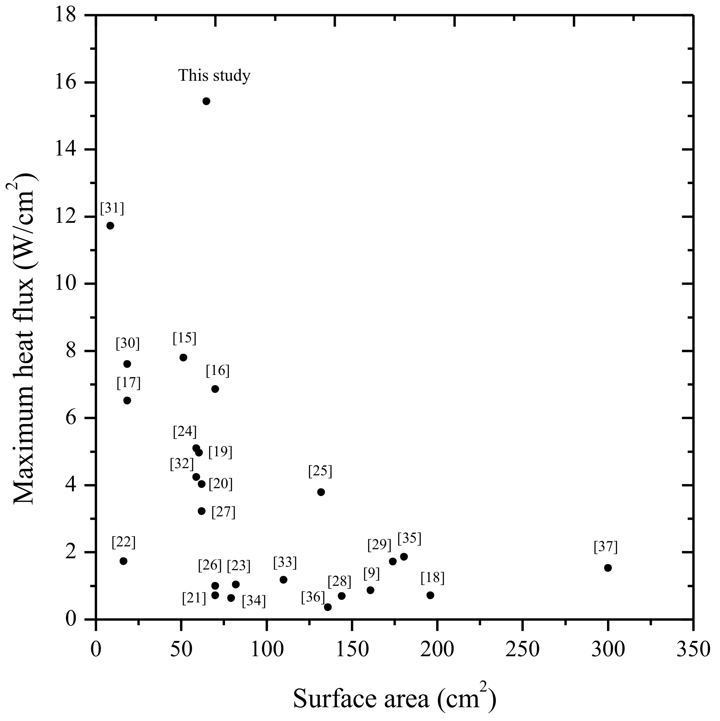
| This study | methanol | 60% | 64.8 | 15.43 |
© 2018 by the authors. Licensee MDPI, Basel, Switzerland. This article is an open access article distributed under the terms and conditions of the Creative Commons Attribution (CC BY) license (http://creativecommons.org/licenses/by/4.0/).
Share and Cite
Tseng, C.-Y.; Wu, H.-M.; Wong, S.-C.; Yang, K.-S.; Wang, C.-C. A Novel Thermal Module with 3-D Configuration Pulsating Heat Pipe for High-Flux Applications. Energies 2018, 11, 3425. https://doi.org/10.3390/en11123425
Tseng C-Y, Wu H-M, Wong S-C, Yang K-S, Wang C-C. A Novel Thermal Module with 3-D Configuration Pulsating Heat Pipe for High-Flux Applications. Energies. 2018; 11(12):3425. https://doi.org/10.3390/en11123425
Chicago/Turabian StyleTseng, Chih-Yung, Ho-Meng Wu, Shwin-Chung Wong, Kai-Shing Yang, and Chi-Chuan Wang. 2018. "A Novel Thermal Module with 3-D Configuration Pulsating Heat Pipe for High-Flux Applications" Energies 11, no. 12: 3425. https://doi.org/10.3390/en11123425
APA StyleTseng, C.-Y., Wu, H.-M., Wong, S.-C., Yang, K.-S., & Wang, C.-C. (2018). A Novel Thermal Module with 3-D Configuration Pulsating Heat Pipe for High-Flux Applications. Energies, 11(12), 3425. https://doi.org/10.3390/en11123425