Research on Commutation and Coordination Control Strategy of Excitation Power Supply Based on Bidirectional Reduced Matrix Converter for Ion Accelerator

Abstract
:1. Introduction
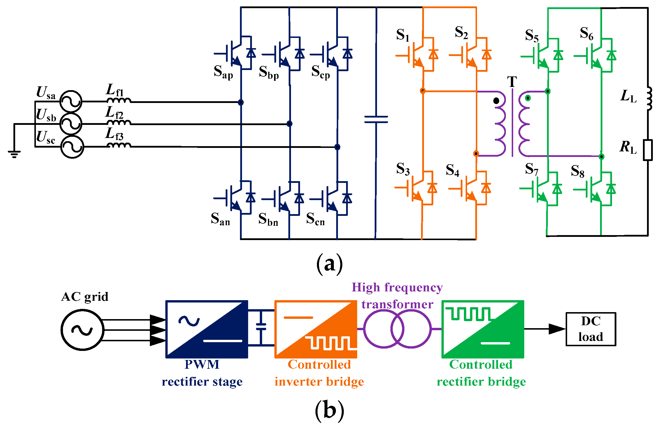
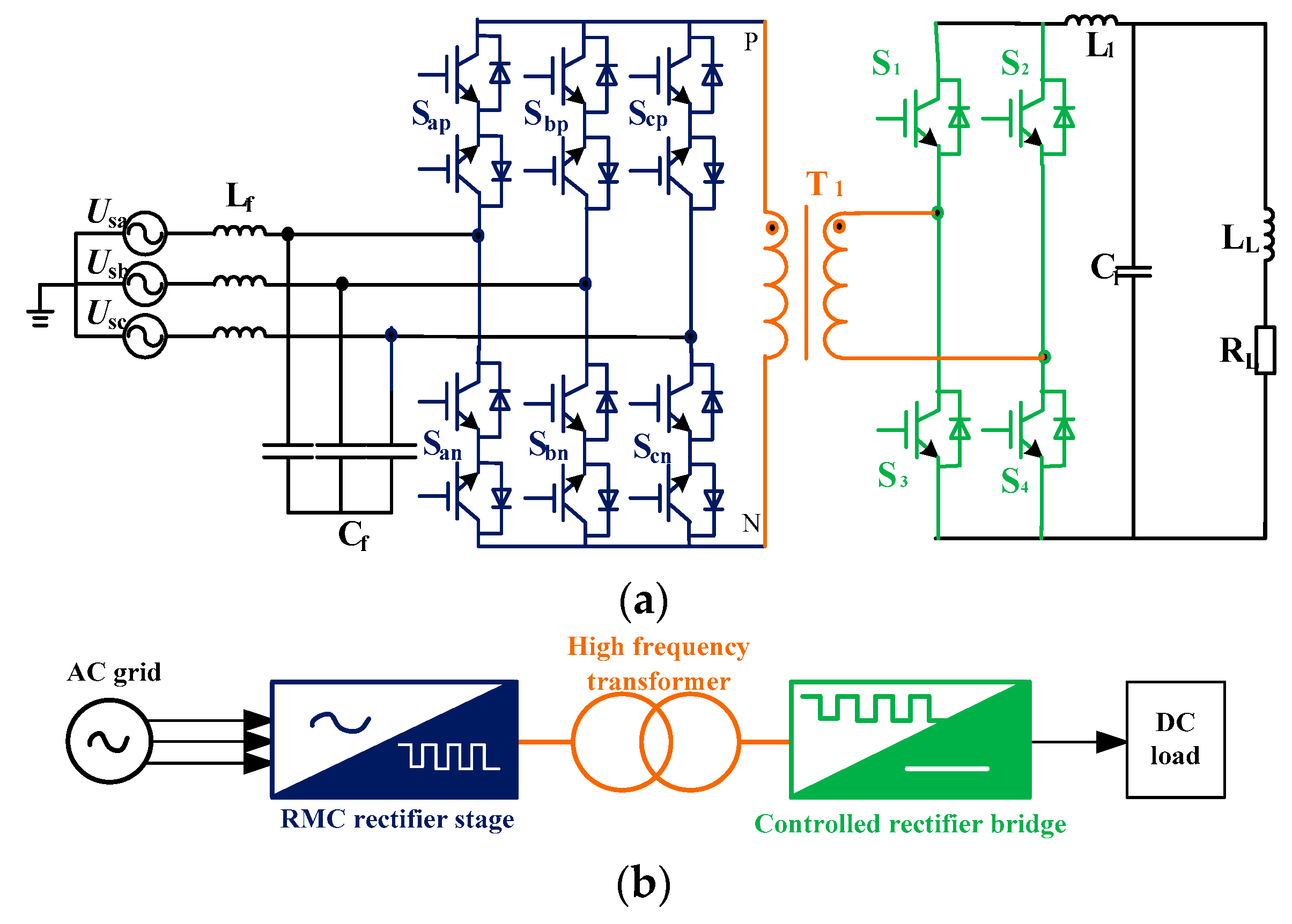
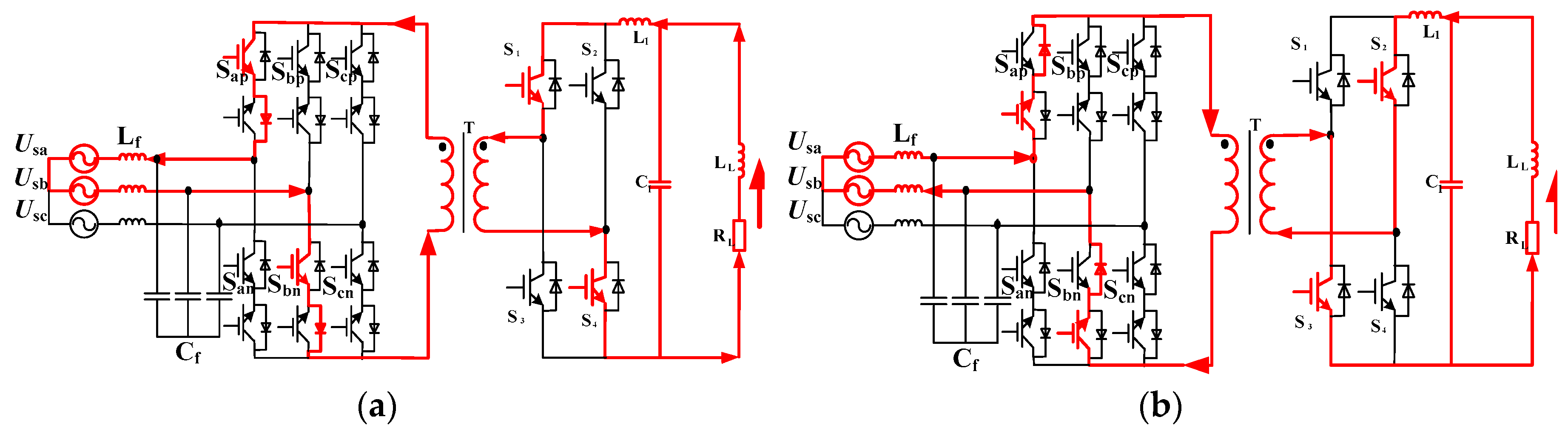
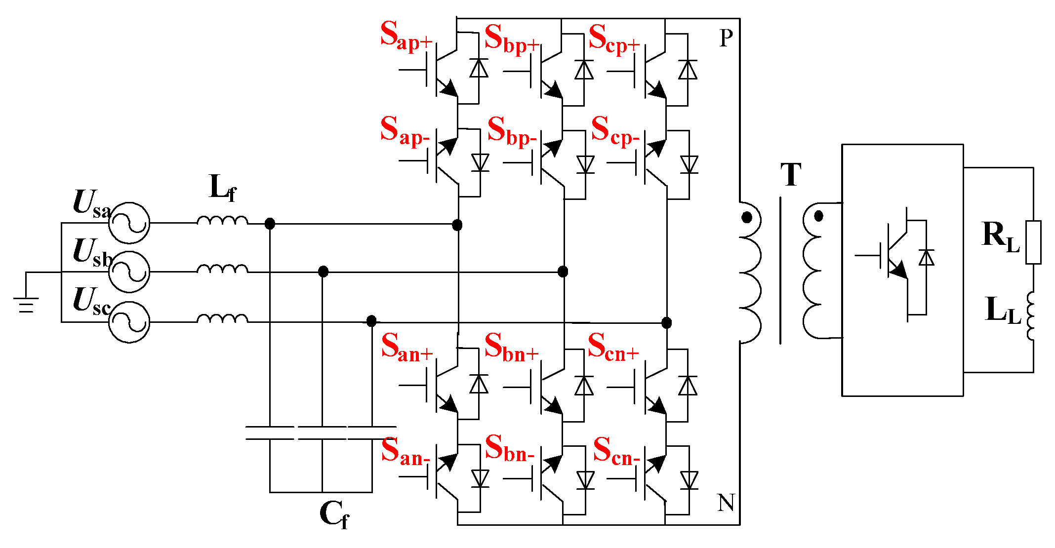
2. Topology of BRMC
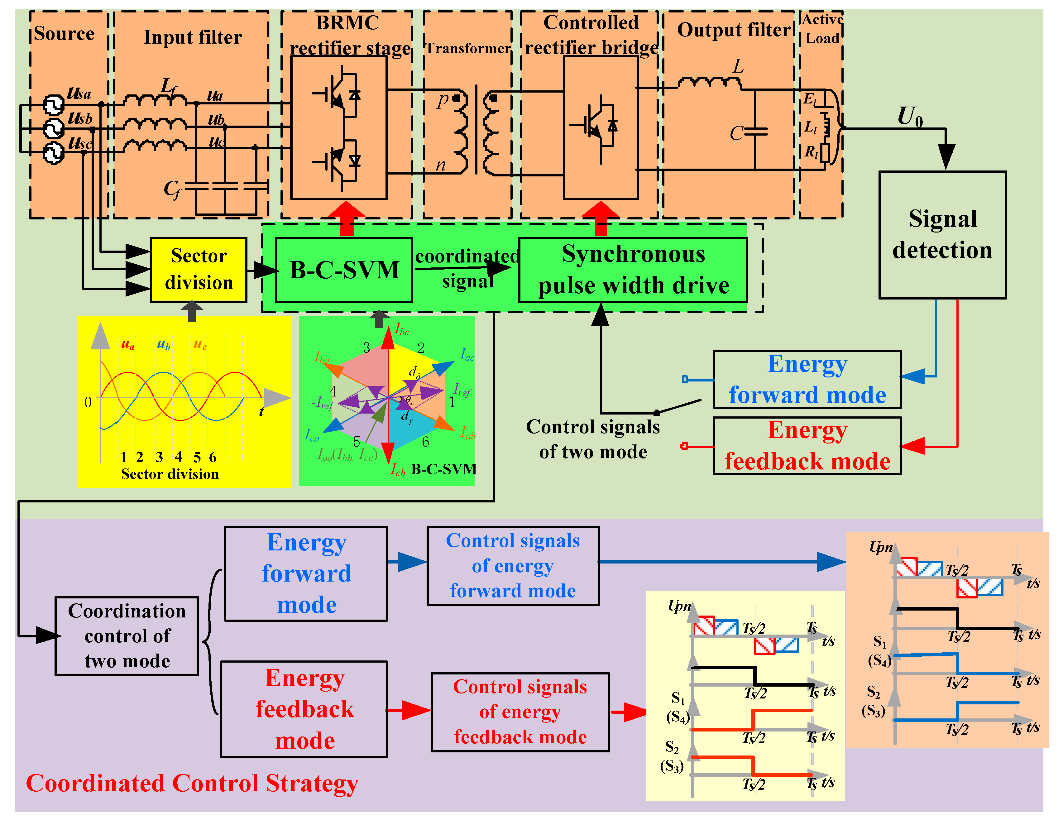
3. Coordinated Control Strategy for BRMC
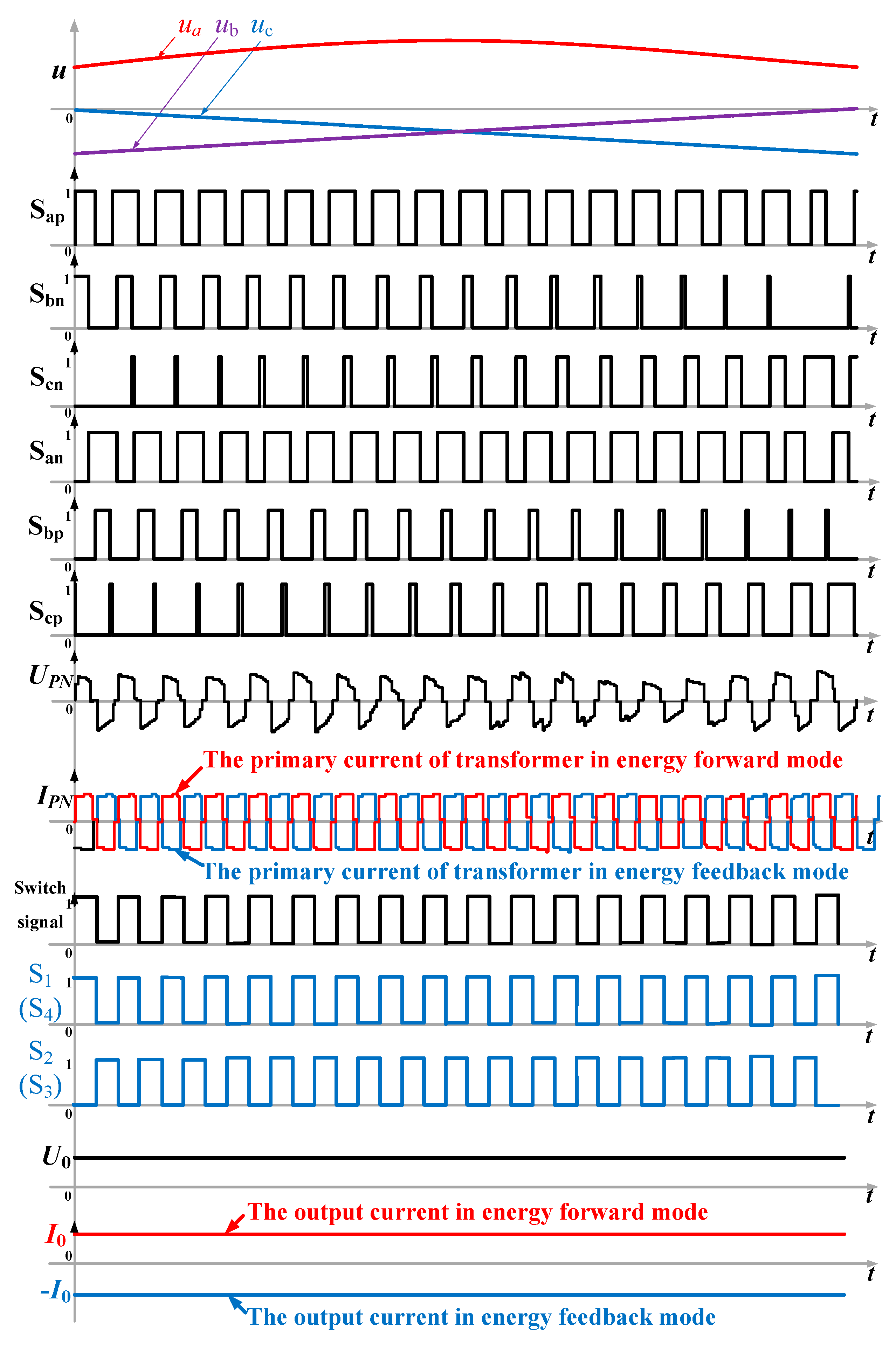
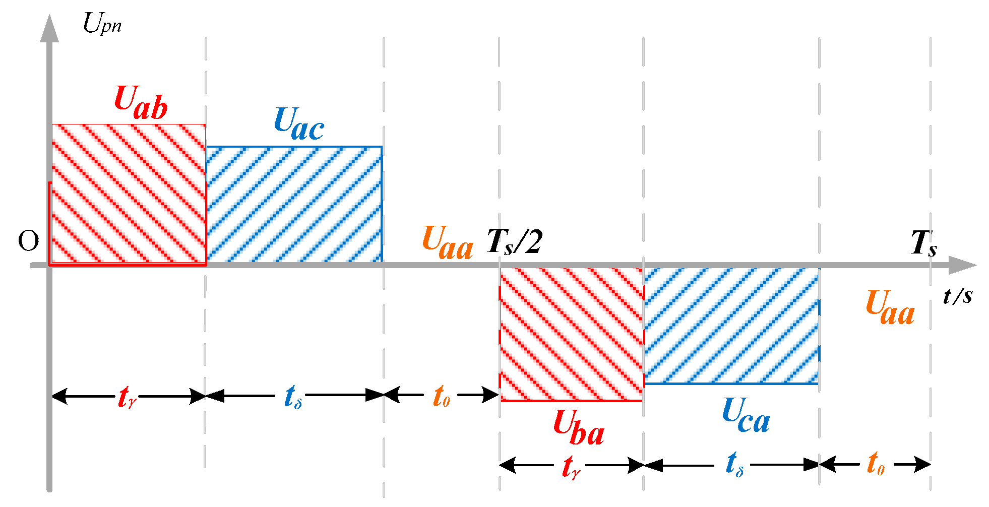
3.1. B-C-SVM for the BRMC Rectifier Stage
3.2. CoordinationStrategy of Controlled Rectifier Bridge
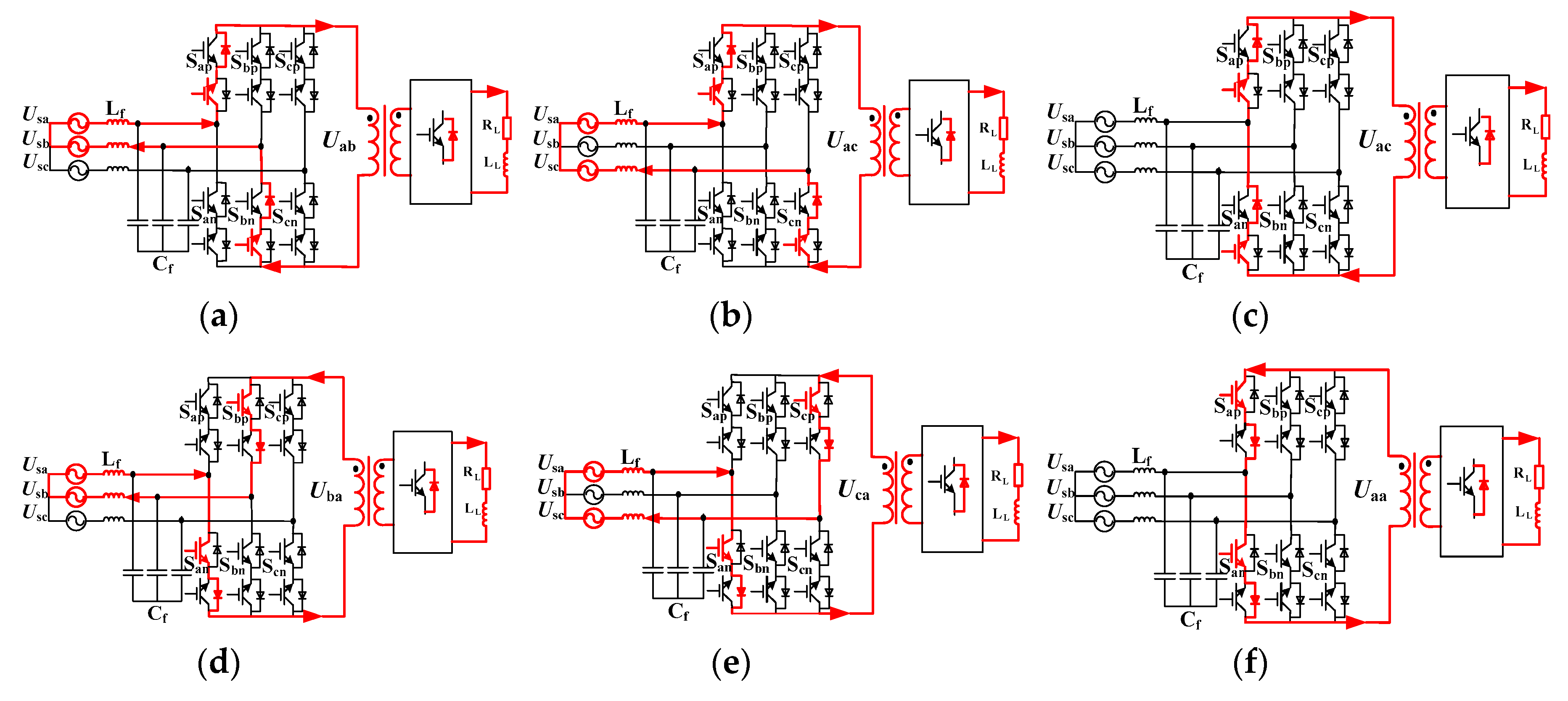
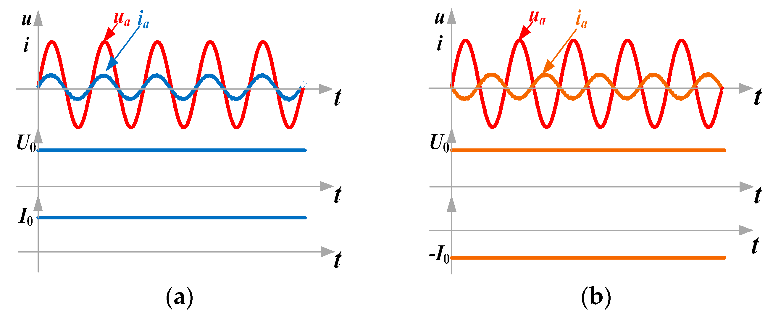
3.2.1. Energy Forward Mode
3.2.2. Energy Feedback Mode
3.2.3. Comparison between the Proposed Method and the Other Methods
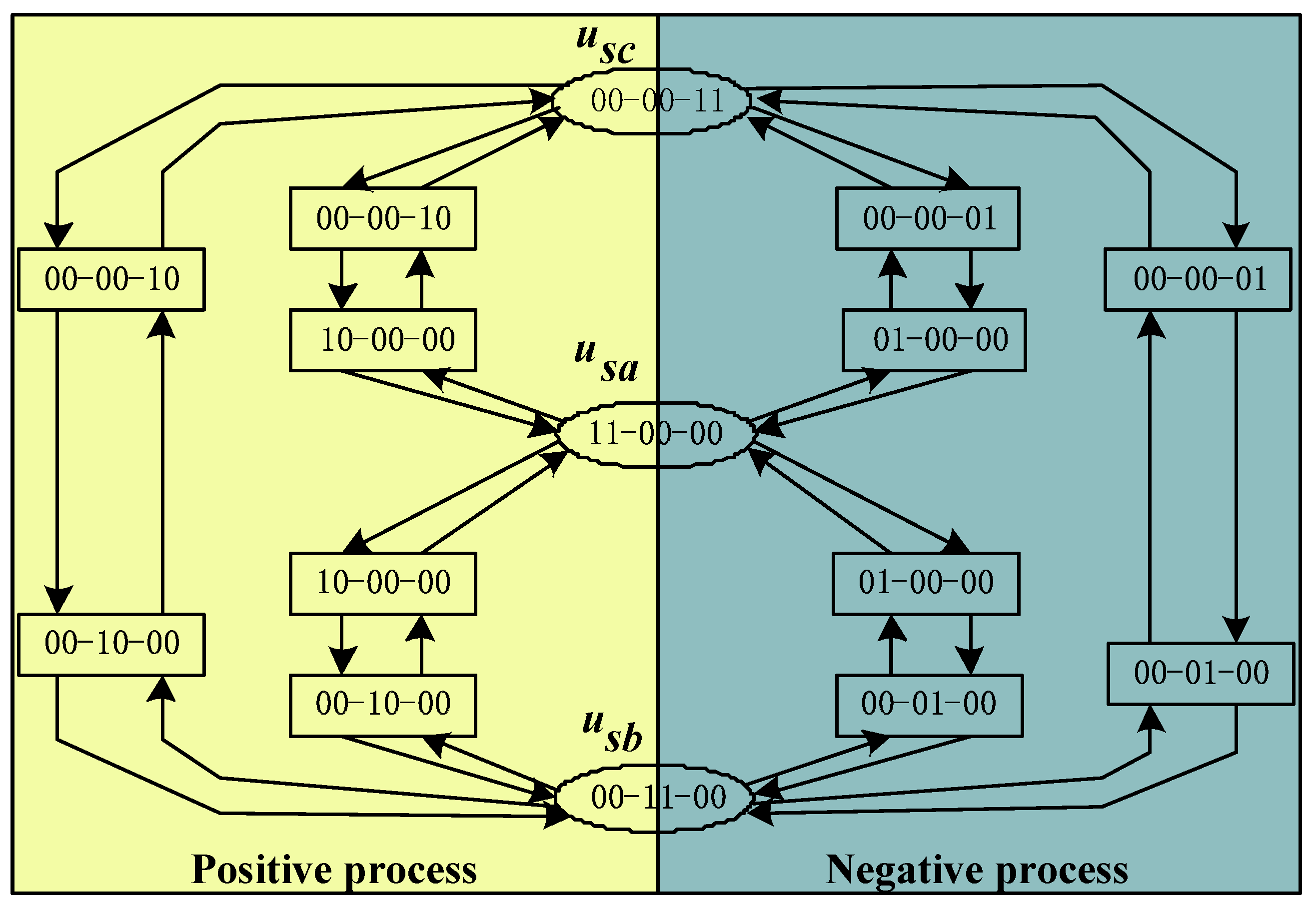
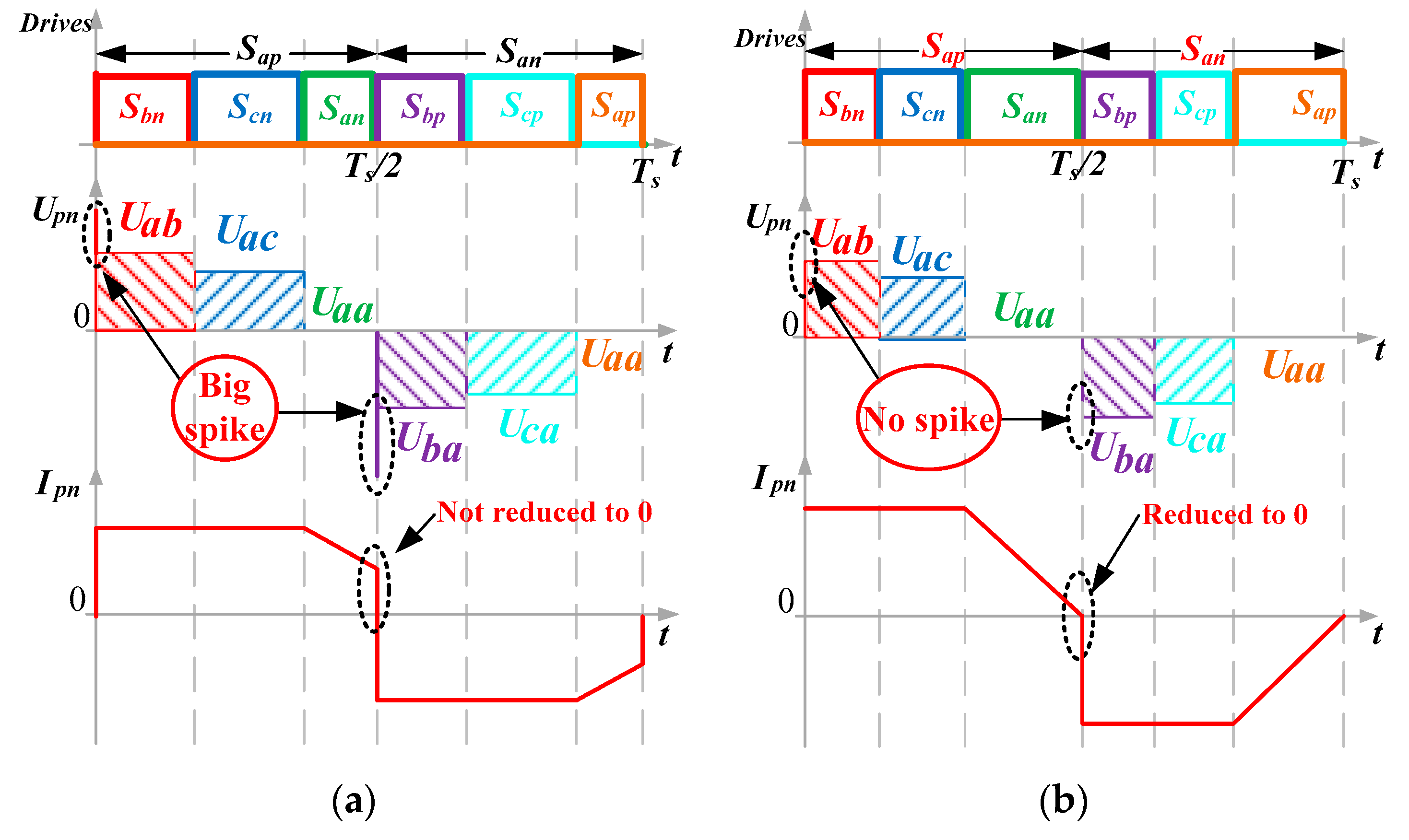
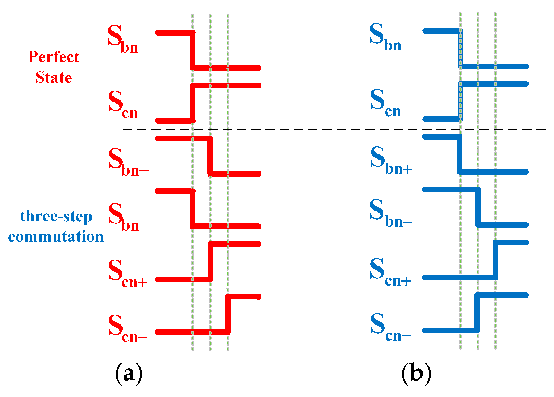
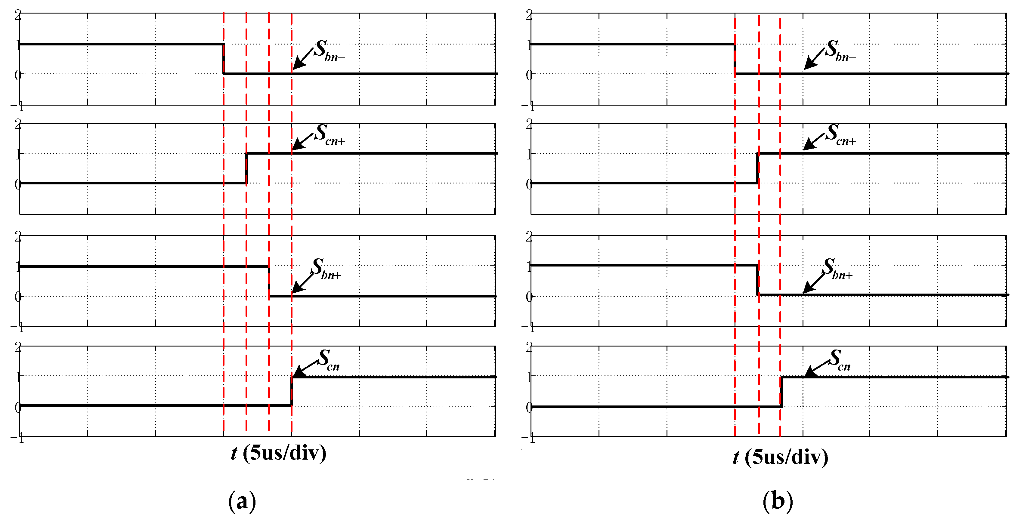
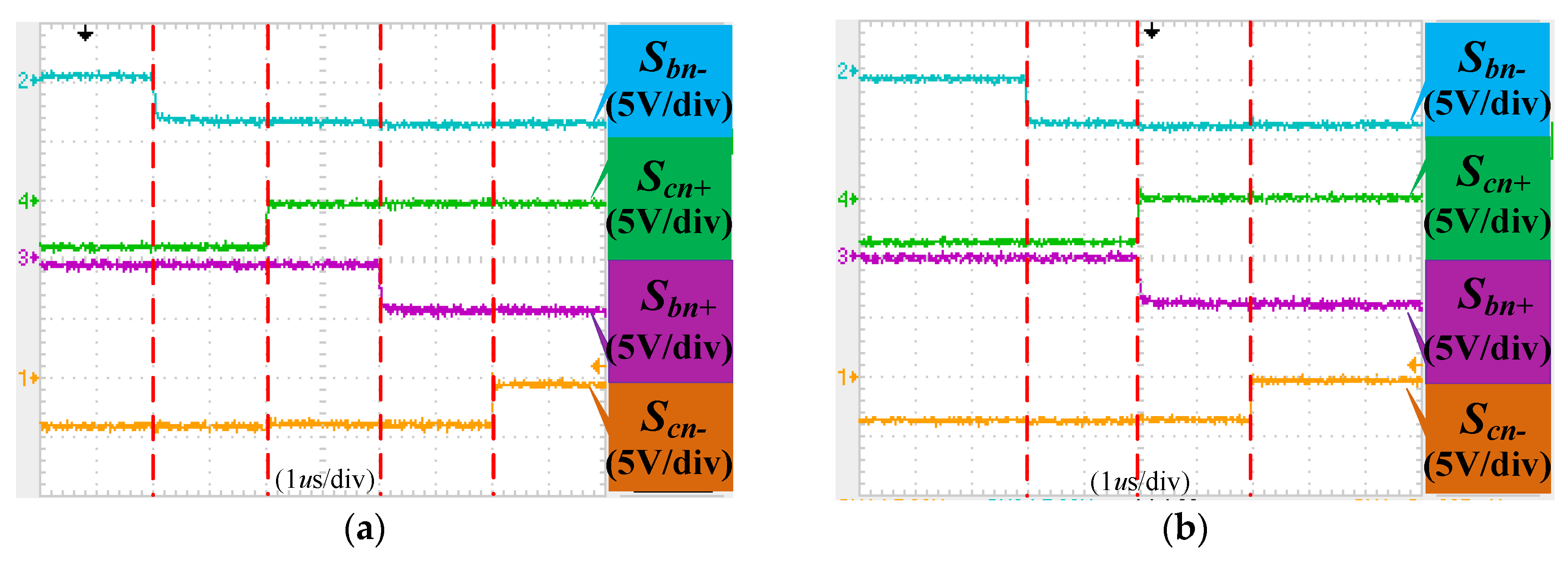
4. Hybrid Commutation Strategy of BRMC
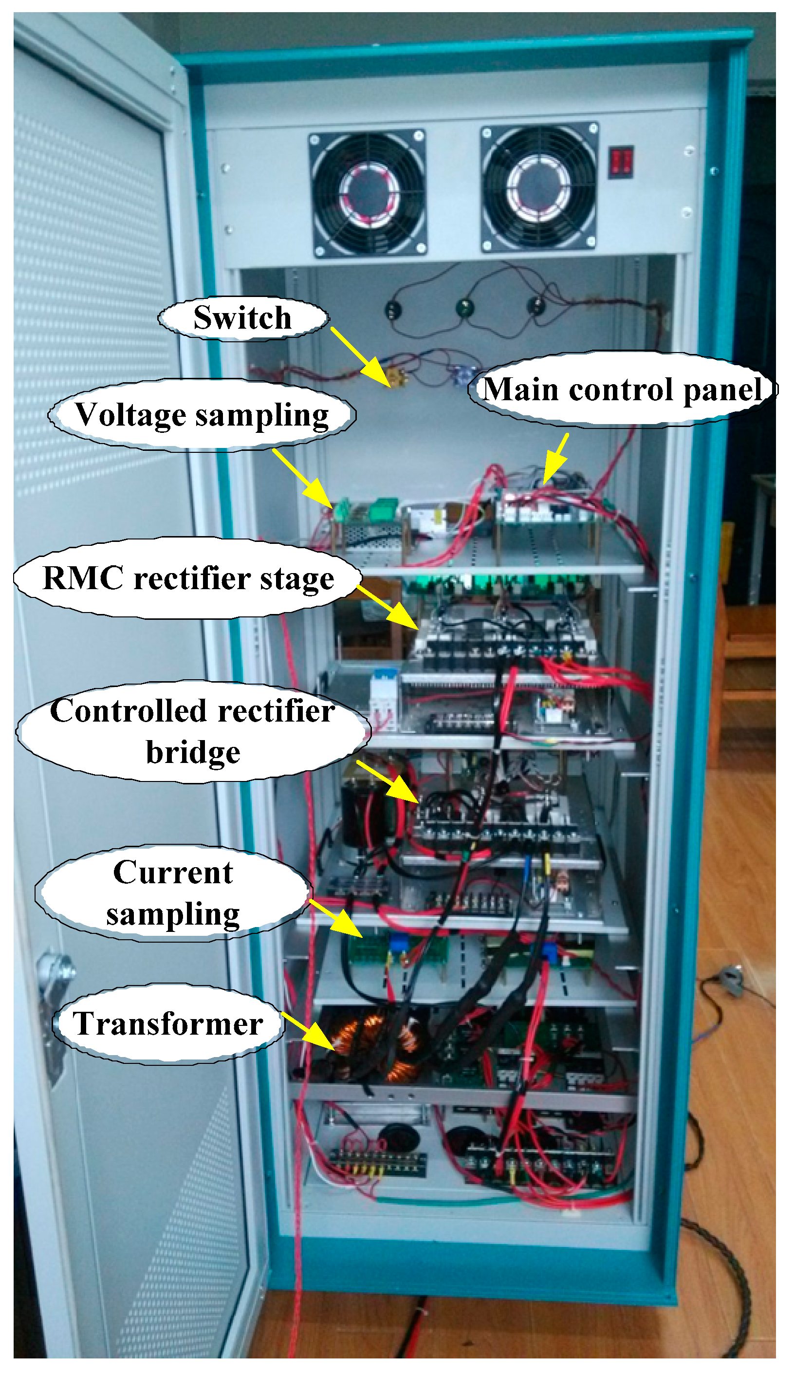
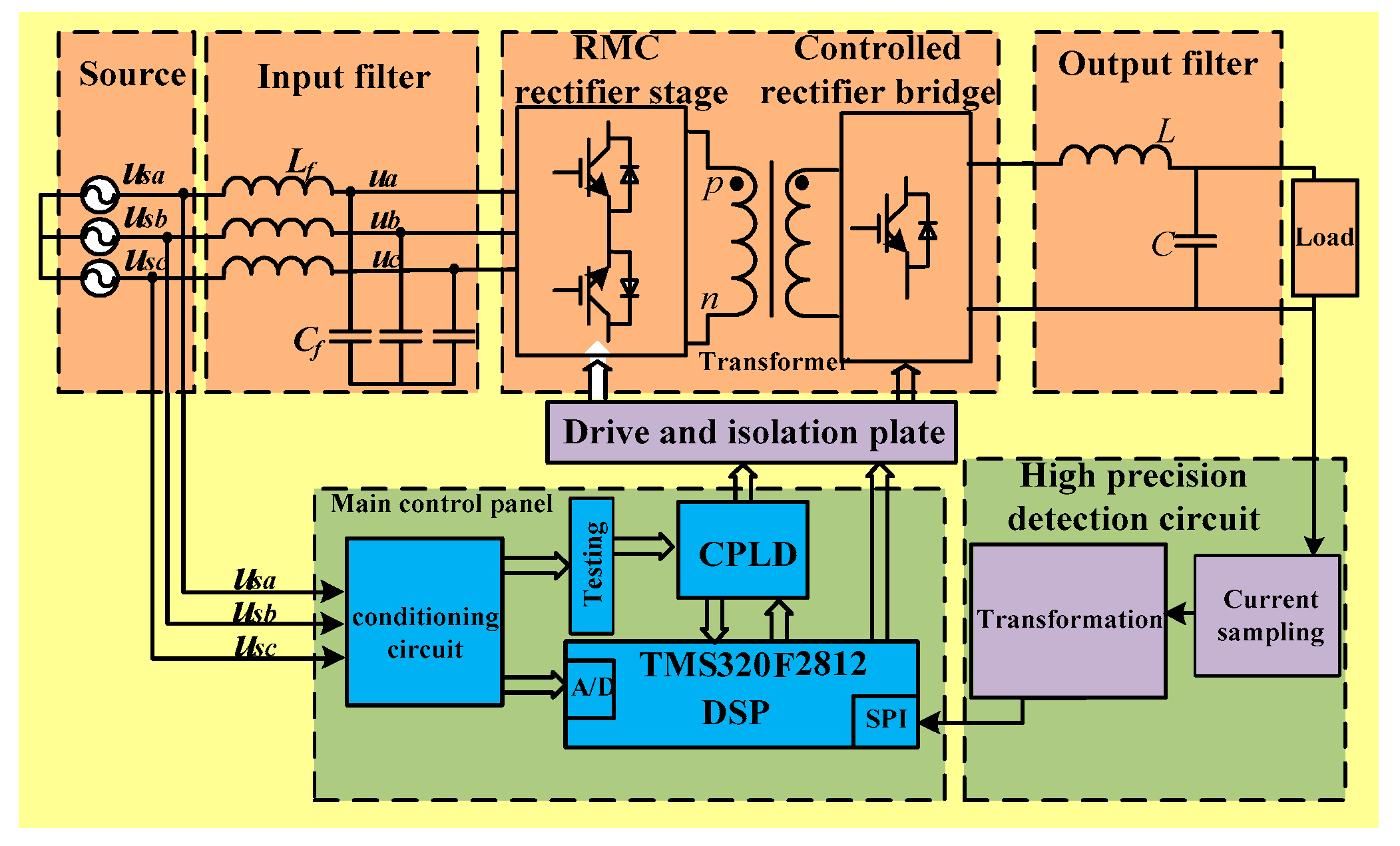
5. Implementation and Prototype of BRMC System
6. Simulation and Experimental Verification
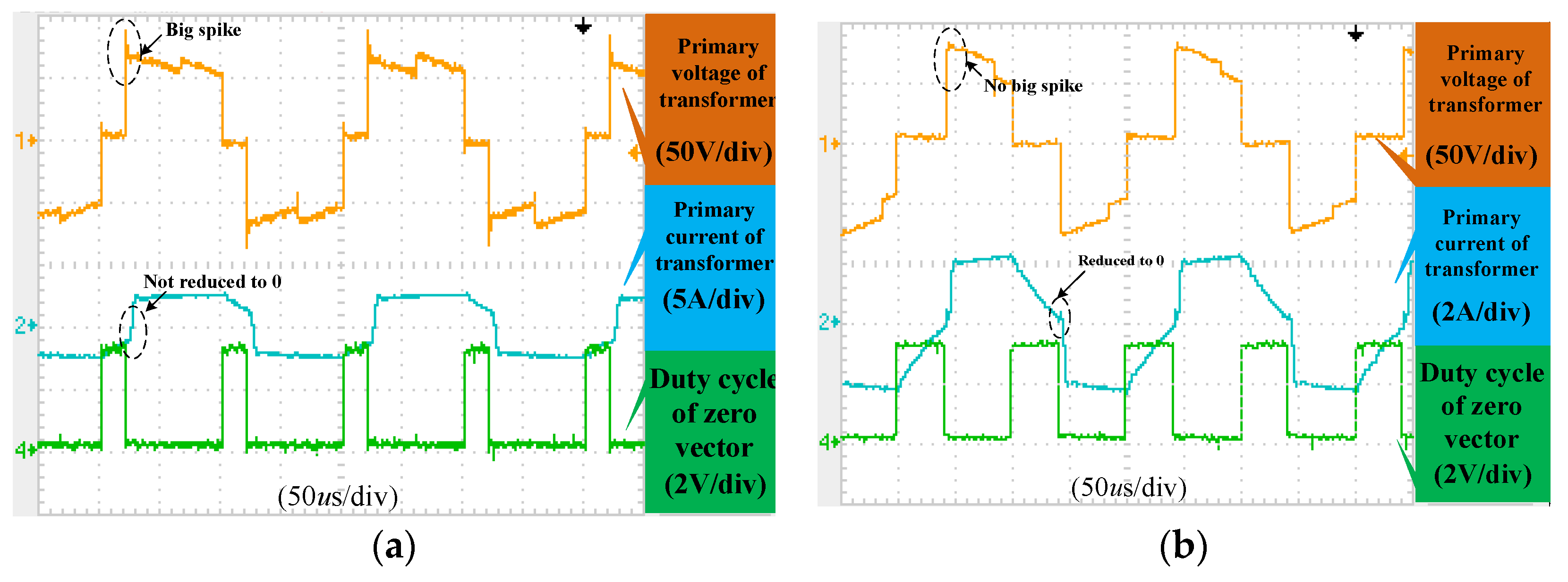
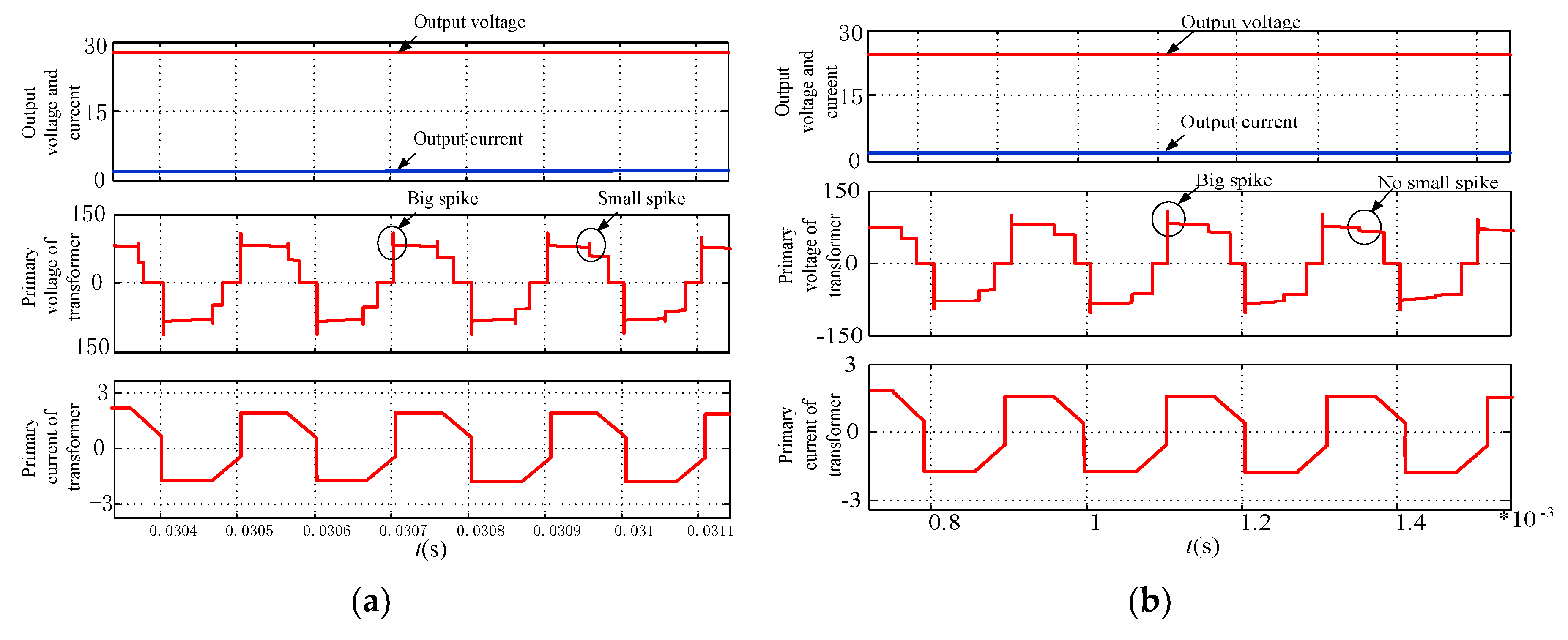
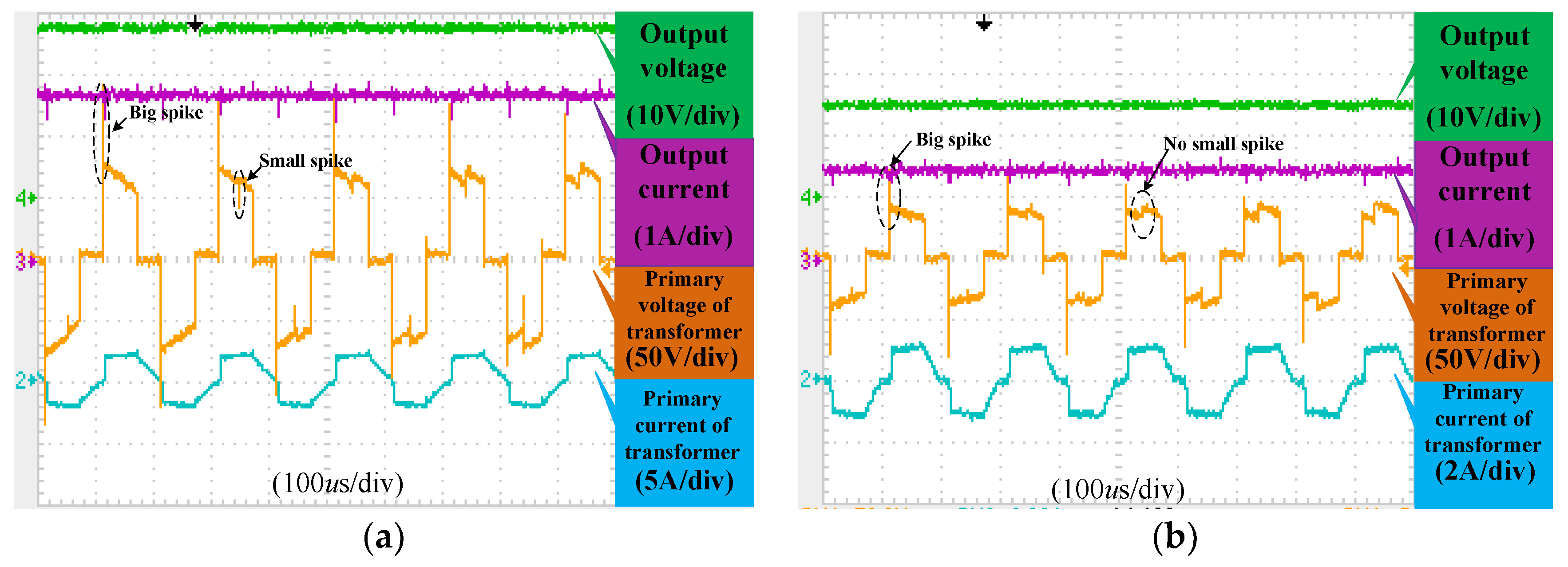
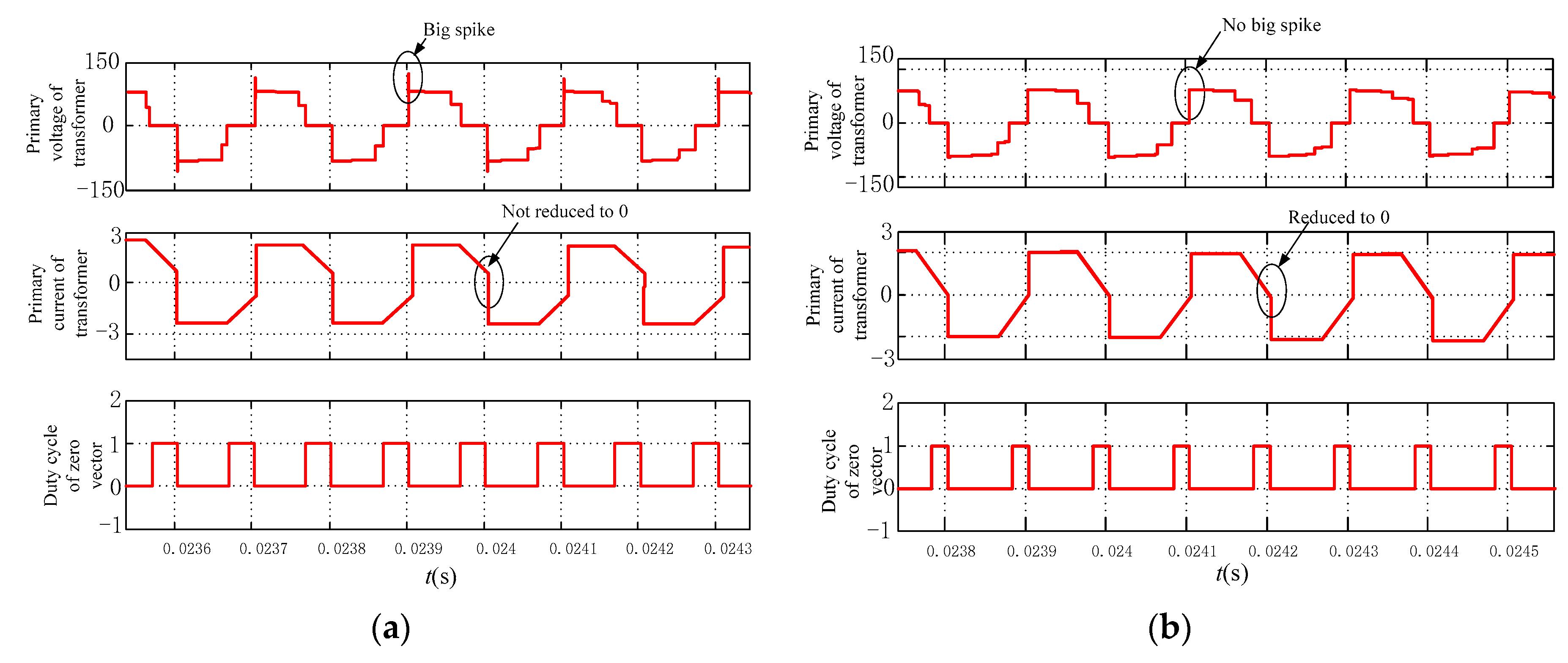
6.1. Validation of the New Commutation Strategy
6.2. Validation of Bidirectional Energy Flow
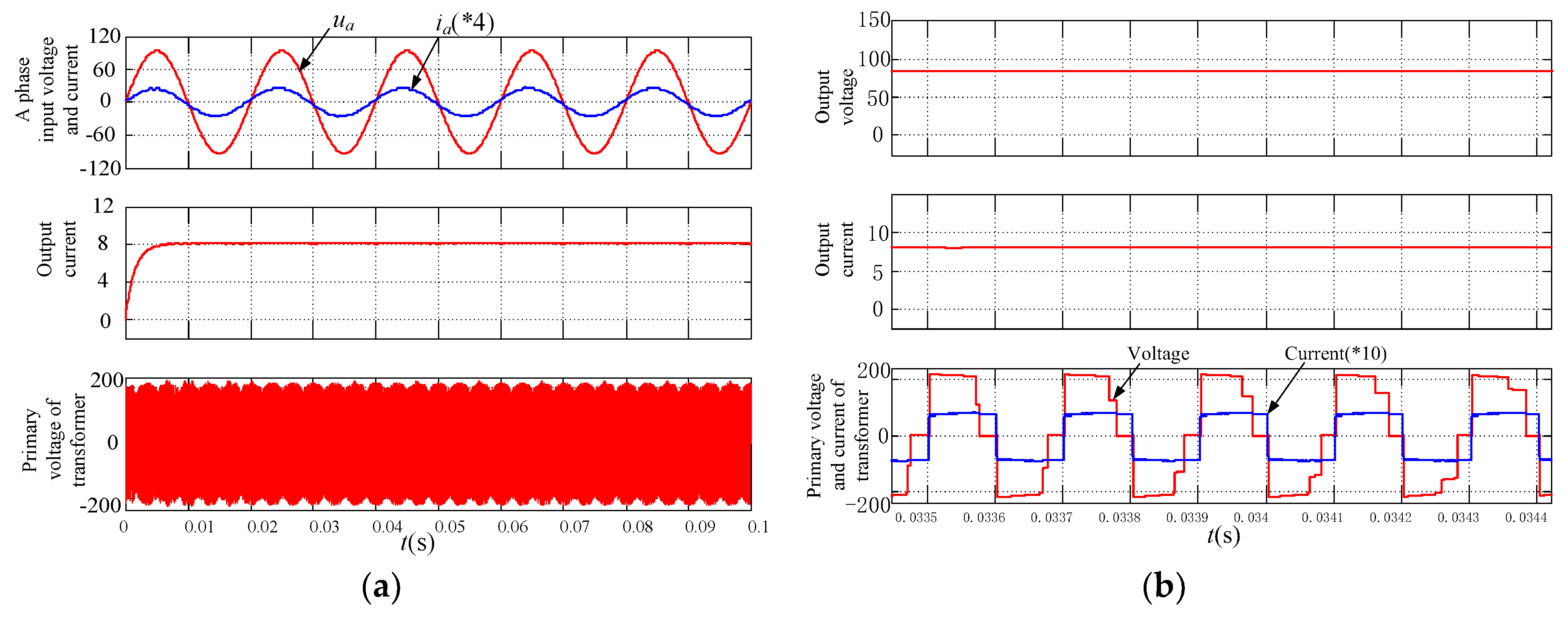
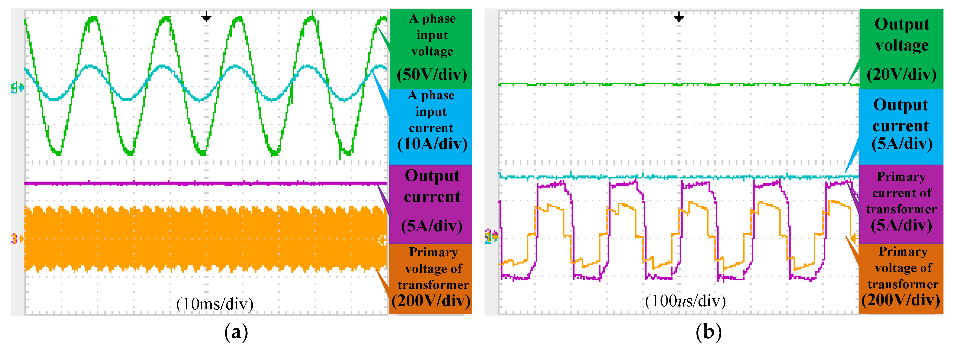
6.2.1. Energy Forward Mode
6.2.2. Energy Feedback Mode
6.3. Dynamic Experiment
7. Conclusions
Author Contributions
Funding
Conflicts of Interest
References
- Furukawa, T.; Shirai, T.; Inaniwa, T.; Sato, S.; Takeshita, E.; Mizushima, K.; Hara, Y.; Noda, K.; Kakutani, N.; Kanai, Y.; et al. Development of Fast Scanning Magnets and Their Power Supply for Particle Therapy. IEEE Trans. Appl. Supercond. 2013, 24, 1–4. [Google Scholar] [CrossRef]
- Hays, S.; Pfeffer, H.; Claypool, B. Design Considerations of a Power Supply System for Fast Cycling Superconducting Accelerator Magnets of 2 Tesla B-Field Generated by a Conductor of 100kA Current. IEEE Trans. Appl.Supercond. 2008, 18, 1411–1414. [Google Scholar] [CrossRef]
- Zhang, G.; Dai, S.; Song, N.; Zhu, Z.; Zhang, J.; Guo, W.; Zhang, D.; Zhang, Z.; Xiao, L.; Lin, L. The Construction Progress of a High-Tc Superconducting Power Substation in China. IEEE Trans. Appl.Supercond. 2011, 21, 2824–2827. [Google Scholar] [CrossRef]
- Kumar, A.; Kumar Sadhu, P.; Kumar Mohanta, D.; Bharata Reddy, M. An Effective Switching Algorithm for Single Phase Matrix Converter in Induction Heating Applications. Electronics 2018, 7, 149. [Google Scholar] [CrossRef]
- Chen, Y.; Zhang, N.; Wang, K. A Series Resonant Filament Power Supply with Variable Structure and Oscillation-Free Switching Strategy for High-Voltage Accelerator Application. IEEE Trans. Power Electron. 2017, 32, 8229–8236. [Google Scholar] [CrossRef]
- Zhang, M.; Zhang, X.L.; Xia, L.L. Modeling and Analysis of Inverter-Type High Voltage Power Supply for NBI Accelerator Grid. IEEE Trans. Plasma. Sci. 2016, 44, 1716–1721. [Google Scholar] [CrossRef]
- Garcés, A.; Molinas, M. Reduced Matrix Converter Operated as Current Source for Off-Shore Wind Farms. In Proceedings of the 14th International Power Electronics and Motion Control Conference, Ohrid, Macedonia, 6–8 September 2010. [Google Scholar]
- Wang, C.; Liao, D.; Cai, H. Design and Research of DC Feedback Type of DC Electronic Load. Electr. Meas. Instrum. 2017, 54, 23–29. (In Chinese) [Google Scholar]
- Singh, A.K.; Jeyasankar, E.; Das, P.; Panda, S.K. A Single-Stage Matrix-Based Isolated Three-Phase AC–DC Converter with Novel Current Commutation. IEEE Trans. Transp. Electrif. 2017, 3, 814–830. [Google Scholar] [CrossRef]
- Wang, Y.; Ding, J.; Shi, L.; Gao, D. Devolopment of Power Supply for HIRFL-CSR Dipole Magnet. Atomic Energy Sci. Technol. 2015, 44, 90–92. (In Chinese) [Google Scholar]
- Burany, N. Safe Control of Four-quadrant Switches. In Proceedings of the IEEE Conference on the Industry Applications Society Annual Meeting, San Diego, CA, USA, 1–5 October 1989; pp. 1190–1194. [Google Scholar]
- Mahlein, J.; Igney, J.; Weigold, J. Matrix Converter Commutation Strategies with and without Explicit Input Voltage Sign Measurement. IEEE Trans. Ind. Electron. 2002, 49, 407–414. [Google Scholar] [CrossRef]
- Sayed, M.A.; Iqbal, A. Pluse Width Modulation Technique for A Three-to-Five Phase Matrix Converter with Reduced Commutations. IET Power Electron. 2015, 9, 466–475. [Google Scholar] [CrossRef]
- Hamouda, M.; Blanchette, H.F.; Al-Haddad, K. Indirect Matrix Converter’ Enhanced Commutation Method. IEEE Trans. Ind. Electron. 2015, 62, 671–679. [Google Scholar] [CrossRef]
- Singh, A.K.; Deshpande, P.P.; Panda, S.K. A Single-Stage Isolated Bidirectional Matrix Based AC-DC Converter for Energy Storage. In Proceedings of the IECON 2017-43rd Annual Conference of the IEEE Industrial Electronics Society, Beijing, China, 29 October–1 November 2017; pp. 2744–2749. [Google Scholar]
- Shi, T.; Wu, L.; Yan, Y.; Xia, C. Harmonic Spectrum of Output Voltage for Space Vector Pulse Width Modulated Ultra Sparse Matrix Converter. Energies 2018, 11, 390. [Google Scholar] [CrossRef]
- Guo, Z.; Zheng, C.; Zhao, L.; Qi, X. Control strategy study of Bi-directional energy storage converter. In Proceedings of the 12th IEEE Conference on Industrial Electronics and Applications (ICIEA), Siem Reap, Cambodia, 18–20 June 2017; pp. 567–571. [Google Scholar] [CrossRef]
- Kan, Z.; Li, P.; Yuan, R.; Zhang, C. Interleaved three-level bi-directional DC-DC converter and power flow control. In Proceedings of the 3rd International Conference on Intelligent Green Building and Smart Grid (IGBSG), Yi-Lan, Taiwan, 22–25 April2018; pp. 1–4. [Google Scholar] [CrossRef]
- Varajao, D.; Araujo, R.E.; Miranda, L.M. Modulation Strategy for a Single-Stage Bidirectional and Isolated AC-DC Matrix Converter for Energy Storage System. IEEE Trans. Ind. Electron. 2018, 65, 3458–3468. [Google Scholar] [CrossRef]
- Wheeler, P.W.; Clare, J.C.; Empringharn, L.; Bland, M.; Apap, M. Gate drive level intelligence and current sensing for matrix converter current commutation. IEEE Trans. Ind. Electron. 2002, 49, 382–389. [Google Scholar] [CrossRef]
- Guo, Y.; Guo, Y.; Deng, W.; Zhu, J.; Blaabjerg, F. An improved 4-step commutation method application for matrix converter. In Proceedings of the 17th International Conference on Electrical Machines and Systems (ICEMS), Hangzhou, China, 22–25 October 2014; pp. 3590–3593. [Google Scholar] [CrossRef]


| Comparison Index | PRB-DAB | BRMC |
|---|---|---|
| High-frequency transformer | Yes | Yes |
| Power density | Normal | High |
| Converter stage | 3 | 2 |
| Efficiency | Normal | High |
| Lifetime | Normal | Long |
| Sectors | dx | dy | d0 |
|---|---|---|---|
| 1 | |||
| 2 | |||
| 3 | |||
| 4 | |||
| 5 | |||
| 6 |
| Sector | Normally Opened Switch | Sequential Switch | UPN | Switches of Controlled Rectifier Bridge | |
|---|---|---|---|---|---|
| 1 | Energy forward | Sap | Sbn, Scn, San | uab, uac, uaa | S1, S4 |
| Energy feedback | San | Sbp, Scp, Sap | uba, uca, uaa | S2, S3 | |
| 2 | Energy forward | Scn | Sap, Sbp, Scp | uac, ubc, ucc | S1, S4 |
| Energy feedback | Scp | San, Sbn, Scn | uca, ucb, ucc | S2, S3 | |
| 3 | Energy forward | Sbp | Scn, San, Sbn | ubc, uba, ubb | S1, S4 |
| Energy feedback | Sbn | Scp, Sap, Sbp | ucb, uab, ubb | S2, S3 | |
| 4 | Energy forward | San | Sbp, Scp, Sap | uba, uca, uaa | S1, S4 |
| Energy feedback | Sap | Sbn, Scn, San | uab, uac, uaa | S2, S3 | |
| 5 | Energy forward | Scp | San, Sbn, Scn | uca, ucb, ucc | S1, S4 |
| Energy feedback | Scn | Sap, Sbp, Scp | uac, ubc, ucc | S2, S3 | |
| 6 | Energy forward | Sbn | Scp, Sap, Sbp | ucb, uab, ubb | S1, S4 |
| Energy feedback | Sbp | Scn, San, Sbn | ubc, uba, ubb | S2, S3 | |
| Parameters | Values |
|---|---|
| Input Voltage | 100 V/50 Hz |
| Input filter | 1.41 mH, 6 uF |
| Output filter | 10 mH, 450 uF |
| Switching frequency | 5 kHz |
| Load | 10 Ω, 10 mH |
© 2018 by the authors. Licensee MDPI, Basel, Switzerland. This article is an open access article distributed under the terms and conditions of the Creative Commons Attribution (CC BY) license (http://creativecommons.org/licenses/by/4.0/).
Share and Cite
Song, W.; Liu, J.; Sun, X.; Wu, F.; Gao, D.; Wang, Y. Research on Commutation and Coordination Control Strategy of Excitation Power Supply Based on Bidirectional Reduced Matrix Converter for Ion Accelerator. Energies 2018, 11, 3396. https://doi.org/10.3390/en11123396
Song W, Liu J, Sun X, Wu F, Gao D, Wang Y. Research on Commutation and Coordination Control Strategy of Excitation Power Supply Based on Bidirectional Reduced Matrix Converter for Ion Accelerator. Energies. 2018; 11(12):3396. https://doi.org/10.3390/en11123396
Chicago/Turabian StyleSong, Weizhang, Jiang Liu, Xiangdong Sun, Fenjun Wu, Daqing Gao, and Youyun Wang. 2018. "Research on Commutation and Coordination Control Strategy of Excitation Power Supply Based on Bidirectional Reduced Matrix Converter for Ion Accelerator" Energies 11, no. 12: 3396. https://doi.org/10.3390/en11123396
APA StyleSong, W., Liu, J., Sun, X., Wu, F., Gao, D., & Wang, Y. (2018). Research on Commutation and Coordination Control Strategy of Excitation Power Supply Based on Bidirectional Reduced Matrix Converter for Ion Accelerator. Energies, 11(12), 3396. https://doi.org/10.3390/en11123396