1. Introduction
Predictive control has strict conjunction with the rendering of a proper mathematical model that will be used to determine a successor step of our control algorithm. Subsequently, the modeling paradigm must become the core issue in projecting the predictive control algorithm of the cyber-physical and the physical processes in general. Even though the process is purely natural, meaning it is a naturally continuous system, influenced by the control algorithm, it will undoubtedly evolve into the Hybrid System (HS). That is why this study points out the results from the aspects of HS controls in the field of Switched Affine Systems (SAS). Nowadays, the majority of power electronics uses a kind of Pulse Energy Conversion or Converters (PEC) in rendering the power sources or control signals. Consequently, these systems are in the group of SAS.
In this study, an alternative approach to modeling a DC-DC boost converter has been provided, and our SAS example is taken into consideration as a good representative of the aforementioned field. A renaissance of the HS theory occurred in 1990s. Simultaneously, the emerging of heuristic control principles happened: neural networks and fuzzy control. The findings of those two mostly separately developed fields will be integrated into the new approaches of the model-based predictive control of SAS. It is necessary to highlight that from the corner of the HS theory, the PEC is analytically definable and well posed [
1]. From the aspects of applicability, we promote the transformation of HS to the purely continuous, although this principle is found to be incomplete by the HS theory [
1]. This is mainly disproven by the inapplicability of the particular HS approaches to fast physical processes. Therein, the assumption that each particular physical process can be presented by Discrete Hybrid Automata (DHA) does not hold. In referring to the qualitative mathematical theory [
2], and the need in DHA to synchronize all of the dynamic events, one faces the problem of multiple dynamics that cannot be unified simply. In previous work [
3,
4], the modeling was put into the focus and given possible solutions from the physical aspects of the system. First, in [
3], the main problem is transferred to the idea of infinity horizon principle. It is comparable with the Model Predictive Control (MPC) infinite horizon, but it should not be mistaken for it. Second, in [
4], the problem is grasped with an idea of two dynamics and unified into one by fuzzy logic (FL).
Some previous academic work have provided remarkable results in applying the advanced control algorithms for the relatively simple example of SAS: a DC-DC boost converter [
5,
6,
7,
8,
9,
10,
11,
12,
13]. As a result, this article underlines the complexity of the controls of the DC-DC boost converter. This complexity has to be known in order to form a more solid basis for understanding the necessity for the advanced control algorithm. The assigned objectives in the control of DC-DC boost converters are the main complexity issue. Consequently, in this study, the standard objectives have been provided, as well as additionally extended with the objective of the applicability issue. The objectives are:
Robustness to the wide system’s parameter changes [PCR]
Short response period and similar to all different operating points [SR]
Optimality related to constraints [OPT]
Stability [S]
Minimization of the nonlinear phenomena for the selected robustness [NFM]
Applicability to the systems with fast refresh rate. [A]
The above-mentioned has to determine the reason for finding a new and advanced approach that can integrate all of the objectives, even though established and notable approaches already exist [
5,
7,
11]. Those methodologies are successful in newer releases [
14,
15], but are still a continuation in a way similarly improving the main and present issues, the processing complexity, and the system discontinuity. The originators of the modeling principles in their releases [
5,
6,
16] direct the modeling to the direction of identification, because of the compelling interest in minimizing the processing complexity. We see that there is still a possibility to improve the well-articulated problems of system discontinuity and processing complexity by reducing the prediction horizon [
17], which is the fundamental stability pillar of the MPC in general. Also, generally for the HS, it is essential to bear in mind that distributing or decoupling the modeling complexity into the several and less complex HS models might be the solution, i.e., current, voltage and feedback; however, then the synchronization of those models to the one and overall DHA should not be endangered [
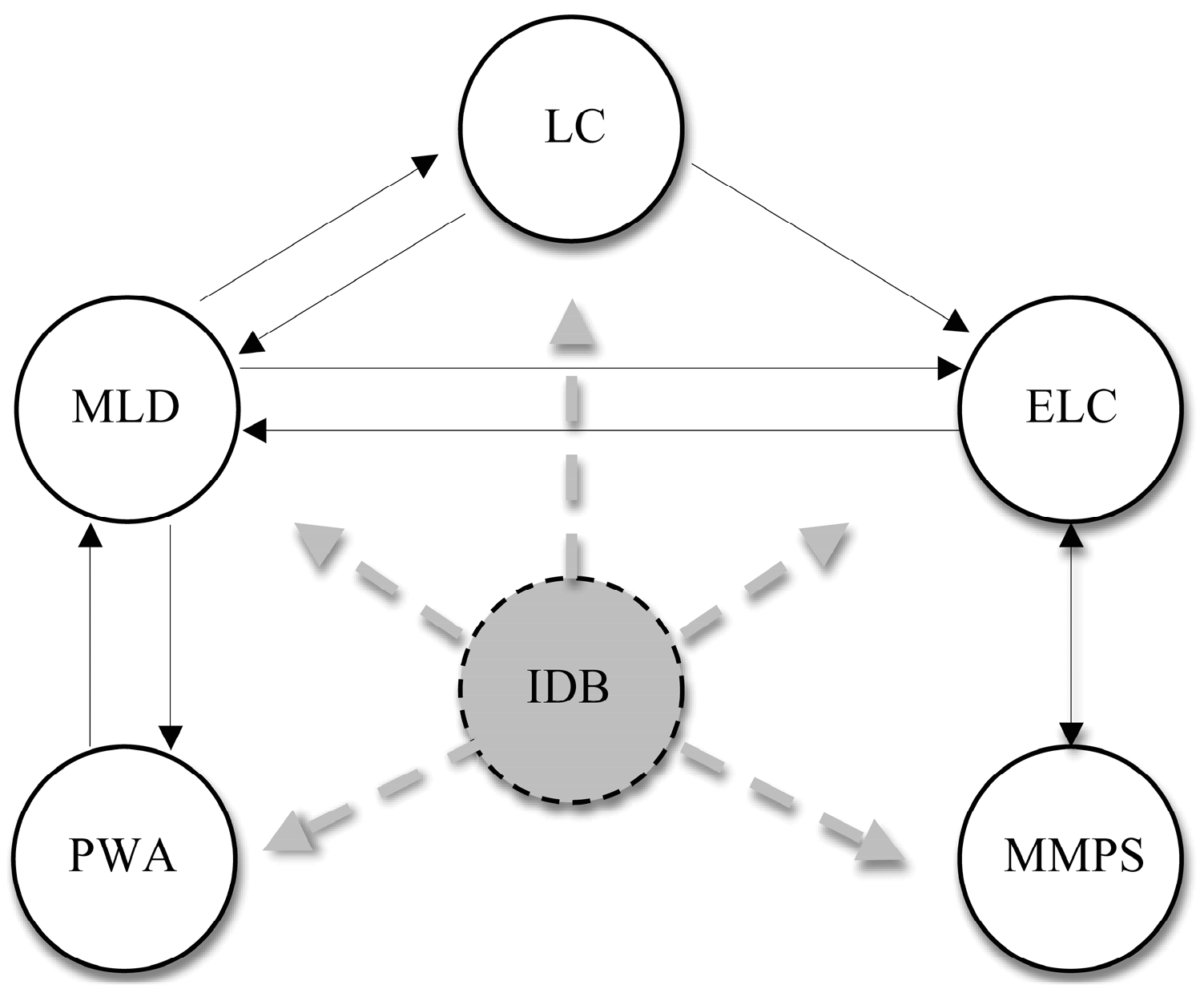
1]. Considering that the main fundament of this study is the presentation of Identification-Based (IDB) modeling and a comparison of those modeling-based control algorithms,
Figure 1 presents it in a broader view. In contrast to typical and basic model representatives in HS [
1], i.e., Piece Wise Affine (PWA) models, Linear Complementarity (LC) models, Extended Linear Complementarity models (ELC), Mixed Logical Dynamical (MLD), and Max-Min-Plus-Scaling (MMPS), the Identification-Based (IDB) modeling represents a new group of models rendered by different identification approaches and algorithms that partly identify the uncertainties in HS models or completely, as in the example of this study. Additionally, and to achieve the selected objectives, the new approach will contain the model-based predictive control strategy reformulated to accommodate the above-mentioned nonlinear system’s dynamics problem. As a continuation of previous work [
3,
4], this study will concentrate more on the comparison of controllers that are rendered by the novel methodologies in seeking more advanced control solutions. Additionally, the subsequent discussion has to contribute to a better understanding of the novelty in the predictive controls that can be widely exploited. Originally, the main goal was to provide a more compact and applicable solution for the DC-DC boost converter that can be integrated into different, more complex, and practical problems. The main complexity is here grasped in the system’s model structure and performed offline. The lifted modeling accuracy that is gained by the identification of a constructed process on the site can help in distinguishing and diagnosing other process problems, as discussed in [
18]. In contrast, it can block the nonlinearities produced by the semiconductors realistically, and not be injected by the trivial nonlinear switching functions, but still be compact in forming the overall model for the more complex examples in [
19,
20]. It will be all based on assumptions that the system states are measurable and the switching period
is fixed. Subsequently,
Section 2 provides a discussion of the distinctive problems in the modeling of SAS that contributes to the complexity and places the novel solution into the methodology frames that are of crucial importance for the understanding of latter compared controllers.
Section 3 presents the successfully applied methods and comparison of the achieved results, and
Section 4 contains the short conclusion.
2. Novel Modeling Paradigm and Predictive Control of a DC-DC Boost Converter, Minimization of Online Processing
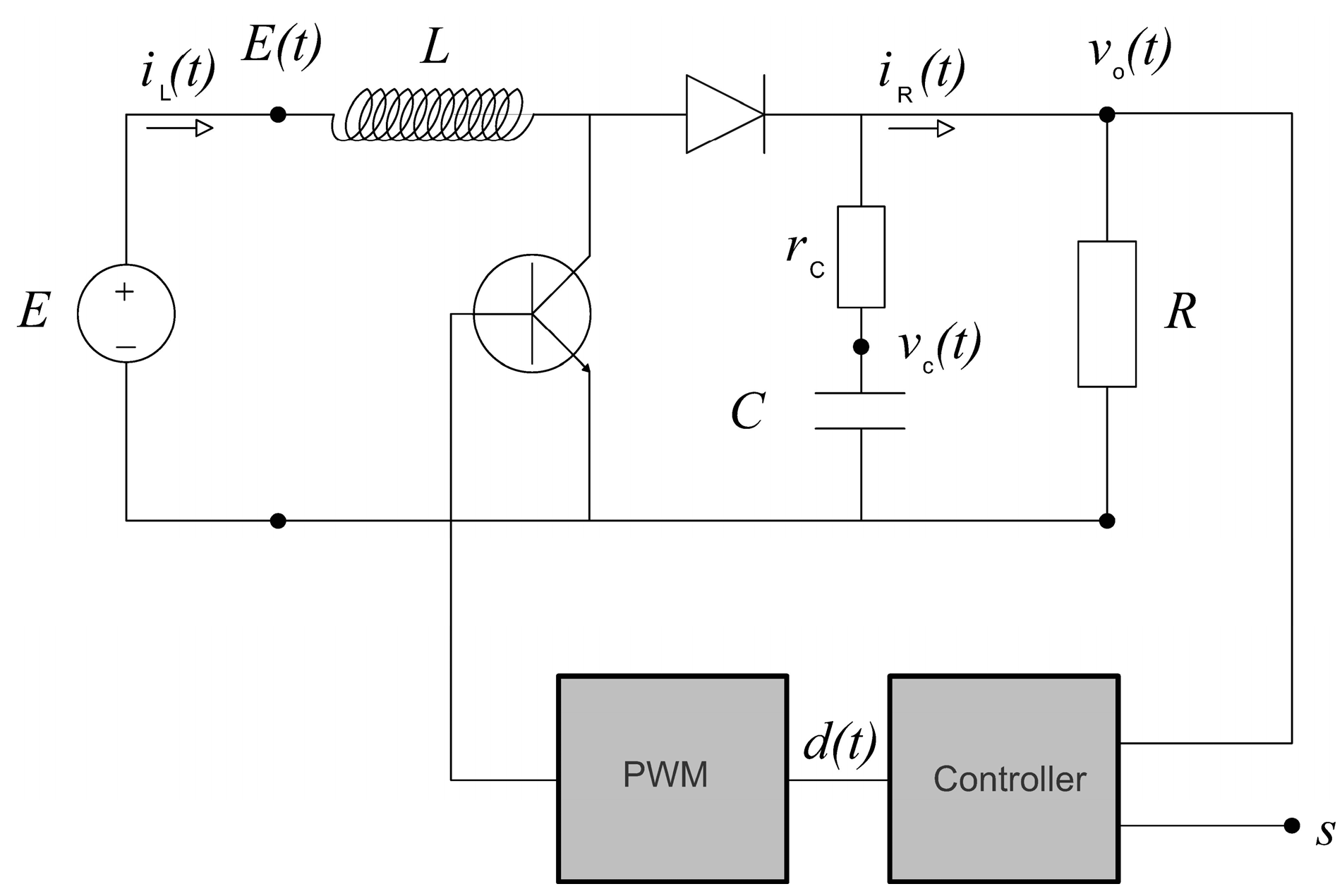
Predictive control must be the main strategy in achieving the robustness and optimality of the final control algorithm of a DC-DC boost converter. Optimality in the controls of the DC-DC boost converter must be seen through the system’s constraints. The main constraints are the voltage source
, the inductor current
and duty cycle
. In
Figure 2, a principal electronic circuit of a DC-DC boost converter is presented, and assigning the mentioned circuit constraints additionally including the converter’s voltage set point
, the output voltage
, the load current
and the capacitor’s voltage
.
To predict a successor control signal of a new control algorithm, a process model has to be known, as well as measured or observed antecedent data. In our case the process model is a mathematical model of the system presented in
Figure 2. Mostly, and as already mentioned, in the broader literature of DC-DC boost converters, several different models are known. Based on the authors’ opinions and knowledge about this particular system, the following distinctive and established methodologies are available:
Small and large signal modeling [
12,
13]
Poincaré mapping in discontinuous conduction mode (DCM) [
7]
HS based modeling; Mixed Logical Dynamical and Linear Complementarity [
11,
21,
22].
Those modeling principles address most of the modeling problems of a DC-DC boost converter, but from the control theory point of view and applicability, there is room for improvement. It is unlikely that the answer or a predefined block that precisely models our natural process could be found in the modern computer toolboxes. Looking from the simulation side and finally from the control side, different natural processes can be similar. Furthermore, the modeling formalisms are prone to upgrades. A good example is HS formalisms and their development [
1]. In the high refresh-rate systems, and before developing the control algorithm, the awareness about proven anomalies that can produce a significant impact on our control algorithm must be present. In the example of a DC-DC boost converter, we highlight the three most distinctive ones:
Anomalies caused by the system nature [
1,
2]
Anomalies caused by the modeling formalisms [
23,
24]
Anomalies caused by the control algorithm itself [
2,
7].
A DC-DC boost converter is a cyber-physical process, which by its nature has a controllable switching process that automatically groups it in SAS as a subgroup of HS. If the switching event would be a time-wise insignificantly short in comparison with the discretization, or if the switching event is just occasionally appearing, then the importance might be minimized or simply distinguished by one bit of information. Otherwise, the significance of that event has to be reconsidered. The pulse width modulation (PWM) of our example is exactly the core issue in the control of a DC-DC boost converter, and subsequently, it has to be viewed through the mentioned existence of the possible anomalies.
The switching event over the semiconductors is burdened with the sticking and grazing effects over the switching manifolds [
2]. For the selected physical system, these anomalies are considered natural.
In an application in which we use the HS formalisms, we must be aware of the typical anomalies as “Live lock” and “Zeno” effect [
1,
2,
23,
24].
Conclusively, when the control algorithm is in operation, the awareness of the nonlinearity phenomena recognized in bifurcations and chaos come into focus and must be treated by the control algorithm itself.
An elevation of the grade of modeling accuracy, in order to avoid previously mentioned anomalies, raises the complexity of the model and consequently the control algorithm, but it is of great importance in the stability of predictive control. Additionally, at the same time, it minimizes the nonlinearity phenomena. The mentioned complex view on modeling and the contemporary minimization of the limited time of processing bring this discussion to an alternative solution that integrates and conciliates two from the first sight disputable extremes. In our previous work [
3,
4], as the answer on demanding tasks, the fuzzy logic-based control algorithms successfully provide the possible solution for expressed complexity, and these will be compared here, including the two additional MPC controllers that are not yet presented, but are based on the same modeling principle. The fuzzy logic is not used traditionally [
9,
10,
25] in a way to formulate the nonlinear gain interpolation, but differently to approximate the complex system model and answer positively to all of the objectives that have been collected together. The modeling benefits that are basically derived from the fuzzy system identification are threefold.
First, apart from the HS structure, in this way the system can be interpreted as a purely continuous system; in the worst-case scenario, it maintains the same grade of accuracy as the HS modeling approach.
Second, it provides the final model that is a more compact solution and minimizes the online processing burden of the control algorithm.
Third, in practical solutions, and because it is based on identification, this modeling principle provides the physical characteristics of the electronic circuits in real operation, which overcomes all possible theoretical miscalculations at once.
To understand the novelty of subsequently compared control algorithms, and to frame the modeling methodologies to the unique approach in studies of a DC-DC boost converter, we highlight the main idea. The most distinct characteristic of the new control algorithms is found in the non-analytical but heuristically-based modeling of a DC-DC boost converter. The source models are Takagi-Sugeno (T-S) fuzzy models derived from the mathematically transferred and normed space of measured system states [
3,
4]. Thus, naturally, the process of measuring, or in the simulation environment the numerical integration, transfers the originally and analytically two-dimensional state space problem of the DC-DC boost converter states
in the six-dimensional
normed vector space
. The newly formed and augmented pseudo-Banach space is derived from the Lebesgue 2 norming of the process variables
, which is expressed by
In the above-developed space, the new methodologies perform a different grey box fuzzy identification process to derive the final fuzzy model of a DC-DC boost converter.
The physical process constraints due to the electrical components that were used in the electric circuit presented in
Figure 2 will be the main experimental foundation in forming the Fuzzy Universes of Discourses
and
, of regression vectors and the scaled duty cycle for each particular identification process subsequently explained. In Expression (2), the universes are formed from the excited DHA simulation model of a DC-DC boost converter to provide the necessary robustness, including the discontinuous conduction mode (DCM) and the continuous conduction mode (CCM) of a DC-DC boost converter:
2.1. Fuzzy Model Structure of the Two Degrees of Freedom Controller, the Prediction and Processing Minimization
Baždarić et al. in [
3] demonstrated the FL identification powerful tool in reconstructing all of the system’s possible steady states. It is done in the wide range of operating points that are defined by altering different process parameters in combinations and providing the expected real and extreme system conditions.
In the five-dimensional normed space (excluding the time)
, the modeling provides a fuzzy model, which is expressed by Equation (3):
that relates the system states and process parameters. In Equation (3), the
is the member (real number) of the fuzzy model parameter matrix
in the
row and the first column, while the
denotes specially
c-clustering defined membership function from the
number of clusters [
3]. Four measured variables of the regression vector
will give information about the process parameters’ change. Instantly and from the previous offline identification process, the fuzzy model relates a linear contribution of inputs, as the T-S consequence functions (3), to the infinity horizon steady duty cycle
.
The model in Equation (3) is a basis for the predictive control of a DC-DC boost converter. As a derived model, Equation (3) is not a dynamic system model, it is used in [
3] in the feed-forward line of the optimized PI controller. The resulting control law is
where
denotes the output from the PI controller. The control signal
is a scaled duty cycle
for the used PWM. The
in Equation (4) is the infinity horizon prediction of the steady-state inductor current
, corresponding to the load current
and the model based reconstructed efficiency ratio.
The control law will guarantee as fast as possible response of a DC-DC boost converter in finding the steady state for a new possible operating point, mostly limited only by the maximum inductor current. As the new predicted steady state is just an approximation with the projected maximum process/model error, the optimized PI controller will be in function to compensate the steady state error. Here, the optimized PI controller’s main function is to regulate the process operation near the operating point, where this type of linear controller was found to be the most effective. The posed control solution agrees with all the previously mentioned objectives and forms the Two Degrees of Freedom controller. Thus, the controller predicts the new steady duty cycle instantly and based on the measured process parameters. The fuzzy model
is an explicit model as the solution of Equation (3) and does not need calculation of the inverse matrix to fulfill the controller’s prediction. It is a Fuzzy Model-Based predictive control that can be compared with the MPC in a sense of infinity horizon prediction [
3]. This feature drastically minimizes the controller’s processing time.
2.2. Fuzzy Model Structure of the Fuzzy Model Predictive Control (FMPC) Controllers and their Processing Minimization
Furthermore, Baždarić et al. in [
4] demonstrated the FL identification powerful tool in reconstructing the system’s dynamic model. In the similarly developed normed space
as the one in [
3], but now 6-dimensional, including the time, the FL identification and modeling will provide the alternative to the analytically derived model of a DC-DC converter. Slightly different than in Equations (2) and (3), the derived fuzzy model will be constructed from the aspects that
is the output and
du is an input with the corresponding universes. Moved from the HS theory, but also from the traditional “averaged switched model”, this fuzzy model renders all benefits of the alternative modeling as mentioned earlier.
As stated in [
4], the fuzzy model
is expressed by
In the Equations (5) the
denotes a first-grade and
a second-grade regression vector. Furthermore,
denotes the parameter matrix of the 1st-grade identification, and
(
p-number of fuzzy rules) is the vector of normalized degrees of fulfillment [
4]. The mentioned vector is the compact expression of the T-S Fuzzy System that consists of Gaussian membership function in the process of fuzzification, the product as the conjunction function in the premise and the center-average defuzzification. The new type of Fuzzy Model that is now expressing the DC-DC boost converter is a T-S fuzzy nonlinear interpolation of
p-linear models identified in the first-grade of identification and further forming the T-S consequence functions. The novelty is that the linear models in the different operating points are not analytically driven, and those are devised by the Least-Squares (LS) identification process in the wider neighborhood of the operating point. Furthermore, this type of approach minimizes the number of rules in the fuzzy rule base and additionally smoothes the nonlinear interpolation [
4]. Equation (6) presents the final state space expression of the DC-DC boost converter, where the matrixes
,
,
are the LS identified matrixes in the neighborhood of the
i-th operating point and
is the unit step function that is used to integrate the identification process error.
As the typical and compared MPC controllers have the time variable inner models
, the state space form evolves in a more compact form, as provided in Model (7):
Herein,
denotes the compact vector of the fuzzy model coefficients at the time
. Those coefficients are profiling our novel FMPC algorithms in the controls of a DC-DC boost converter. As
Section 3 compared FMPCs that, after the modeling part, are built typically (reference model, preceding horizon principle and filtering) [
26,
27], the control laws will be omitted. Here, we present the cost functions
and the suppression factor
that have been used to form the compared MPC algorithms:
Fuzzy Dynamic Matrix Control (FDMC)
Fuzzy Generalized Predictive Control (FGPC)
Fuzzy Predictive Functional Control (FPFC)
During the control horizon
, the FDMC cost function (8) minimizes the error between the model-based prediction
and first-order reference model
, which is additionally weighted by the state weighting factor
. The control signal
(8) is suppressed by the suppression factor
. In Equation (9), we see the augmented model state vector
which contains the filtered output from the second order filter
[
22] and no state weighing factor. The FPFC cost function in Equation (10) is different and additionally minimizes the computation burden, as it calculates for
a number of coincidence points
during the control horizon and minimizes the vector of the control signals for those points
[
4,
21,
22]. It is important to add that the suppression factor
, when comparing FMPCs, is the inner model-based adaptive and time variable factor
λ(
k) =
aSUPP ⋅
ym(
k + 1) ⋅
u(
k)
−1, where
aSUPP denotes the tuning coefficient [
4].
To demonstrate a minimization of the online processing done in [
4] by the state space dimension reduction, the model state space matrixes that are presented in the MLD model in [
28] are provided:
The state-space equations in Model (11) present the final solution in the MLD approach, which consists of the characteristic state space matrixes
A,
B,
C,
D, where the
A,
B are derived from the intermediate matrixes
Adi,
Bdi as the result of discretization processes during the
time. Thus, in Model (11), the state vector
consists of the inductor current and output voltage, the input is provided by
as the five-dimensional vector of logic variables, and
is the MLD seven-dimensional auxiliary variables’ vector. The matrixes
form the set of selected inequalities as the subject to the optimization [
28].
It is obvious that in the examples in which we use the Model Predictive Control (MPC), a dimension of the state space model matrixes ( in Model (11) and in Model (7)) has the extreme impact on the online processing time. Thus, in comparison with the simplifies the final model predictive state matrix. For the n horizon prediction, the model predictive state matrix is , if the and are the number of rows and columns, respectively, of the original model state matrix.
3. Simulation Results of the Novel Control Methods and Their Comparison
Although in this study a Discrete Hybrid Automata (DHA) and the equivalent model of a DC-DC boost converter are considered to be the online processing time complex, it is a recommended basis for forming the simulation model of the MATLAB/SIMULINK platform [
29]. For the novel control methods, it is a source in exploring the identification methodologies and later application to the physical processes. Thus, the developed methods will be simulated and applied to the DHA-developed simulation model. A minimum discretization or the sampling time in modeling the PWM, and switching events of the semiconductors, is set to 1
while a DC-DC boost converter model sampling time
is 333
. The simulation process was not done in real time; we left enough time to process the DHA simulation model itself together with the developed control algorithms. To provide a meaningful comparison, we use the test parameters or system events that are applied in [
3]. The selection of the operating points and the process parameter change have to prove the robustness of the control algorithms driven from the minimum borders of a DCM to the maximum borders of the CCM of a DC-DC boost converter. In this comparison, we will also present the MPC-developed methods that were not found to be sufficiently compact, and their processing time was short enough to be applied in the physical experiment of [
4]. Subsequently, the Fuzzy Generalized Predictive Control (FGPC) algorithm, the Fuzzy Dynamic Matrix Control (FDMC), the Fuzzy Predictive Functional Control (FPFC), the optimized PI control, and finally the Two Degrees of Freedom (TDOF) control will be tested for the same combination of the system parameters’ change, and their dynamics and steady states will be subsequently compared.
The simulation block diagrams of discussing control algorithms can be found in [
3,
4]. The FMPC methods are based on the same internal model (7) as described in
Section 2.2 and [
4]. Furthermore, a TDOF control methodology is described in
Section 2.1 and [
3], and an optimized PI controller as the reference to all of the comparisons is described in both articles. The latter control solution is intentionally chosen to simplify any of the following comparisons, as its construction is based purely on the standard toolbox of the used simulation platform [
29] and optimized by the Integral of the Time Weighted Absolute Error (ITAE) criterion.
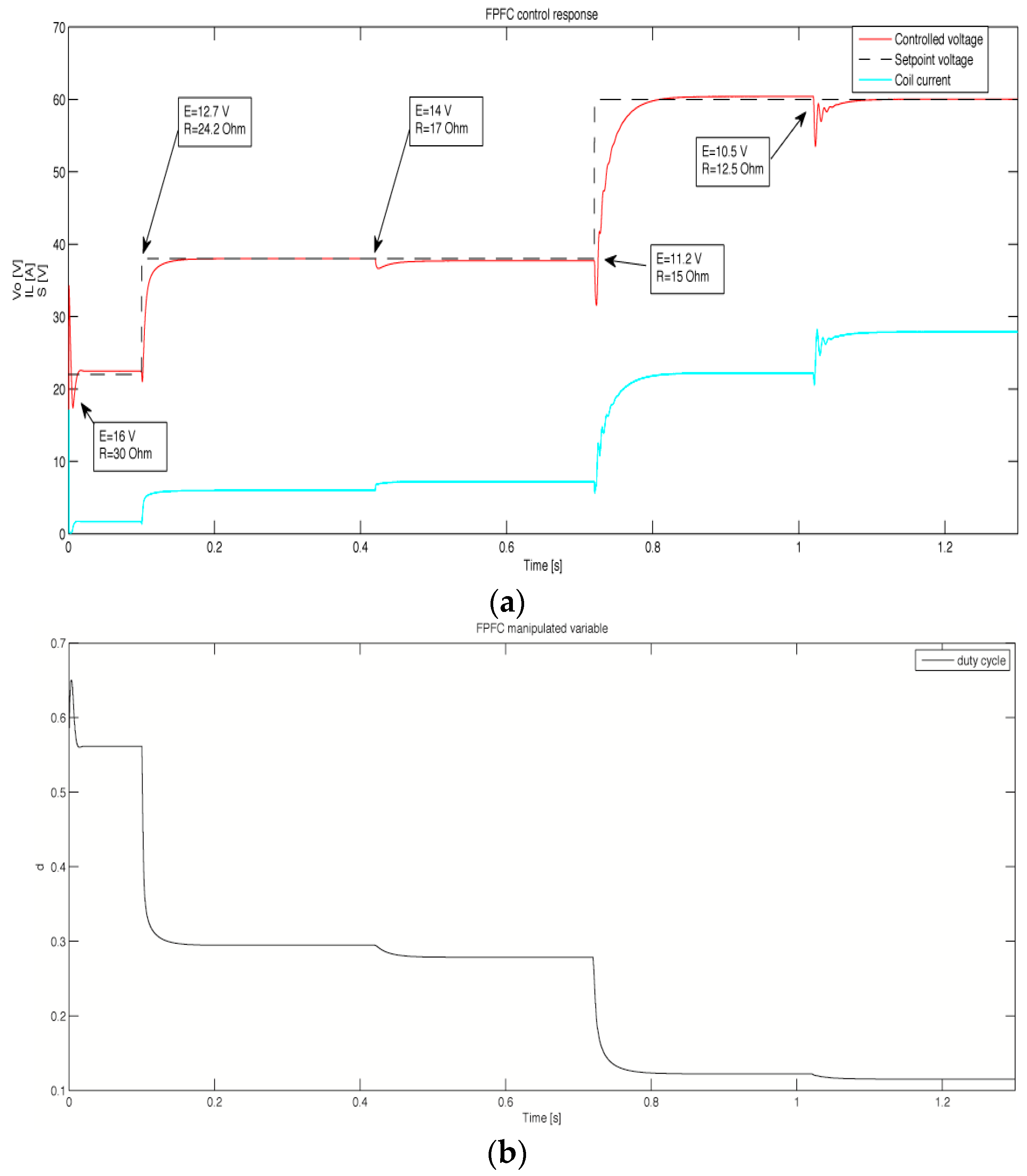
In
Figure 3a, the response of the most favored predictive control solution FPFC is presented. It comes from the online processing time span and aggressiveness in the transition time. The online processing time is again proportionally related to the number of the prediction points, but in the nature of this MPC method, it is the reduction of coinciding points by the implementation of basis functions [
26]. Furthermore, in the figure, there is the curve of the inductor current function that demonstrates a controller’s controlled manner of the most critical constraint of the DC-DC boost converter. Separately from
Figure 3a,
Figure 3b presents the manipulated or controlling parameter that is a duty cycle of a DC-DC boost converter.
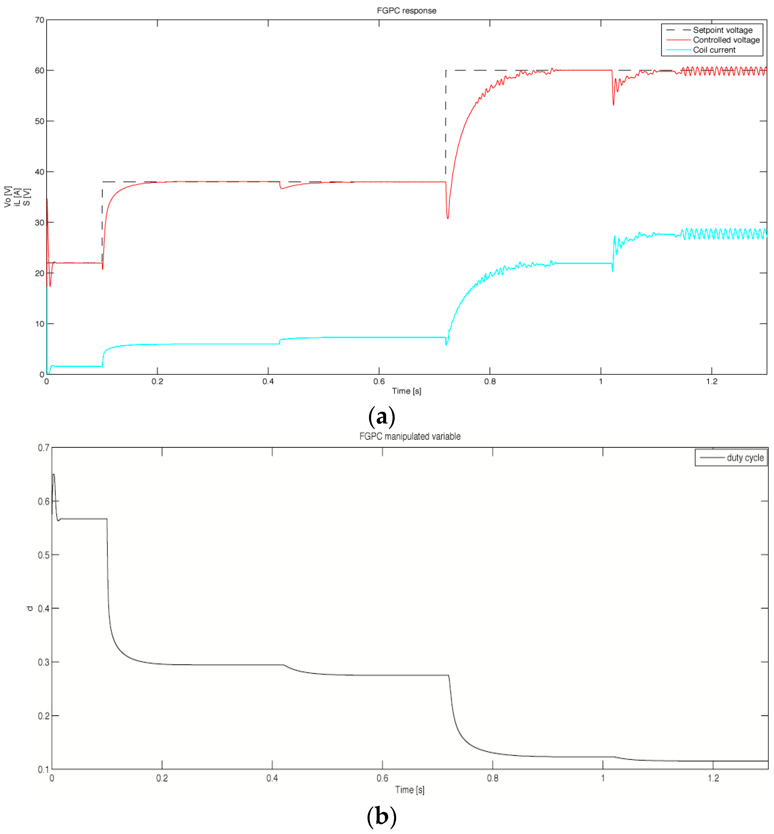
In the sequel, the result of the simulation process for the FGPC, FDMC, the optimized PI, and the TDOF method is presented in
Figure 4,
Figure 5,
Figure 6 and
Figure 7 respectively.
In
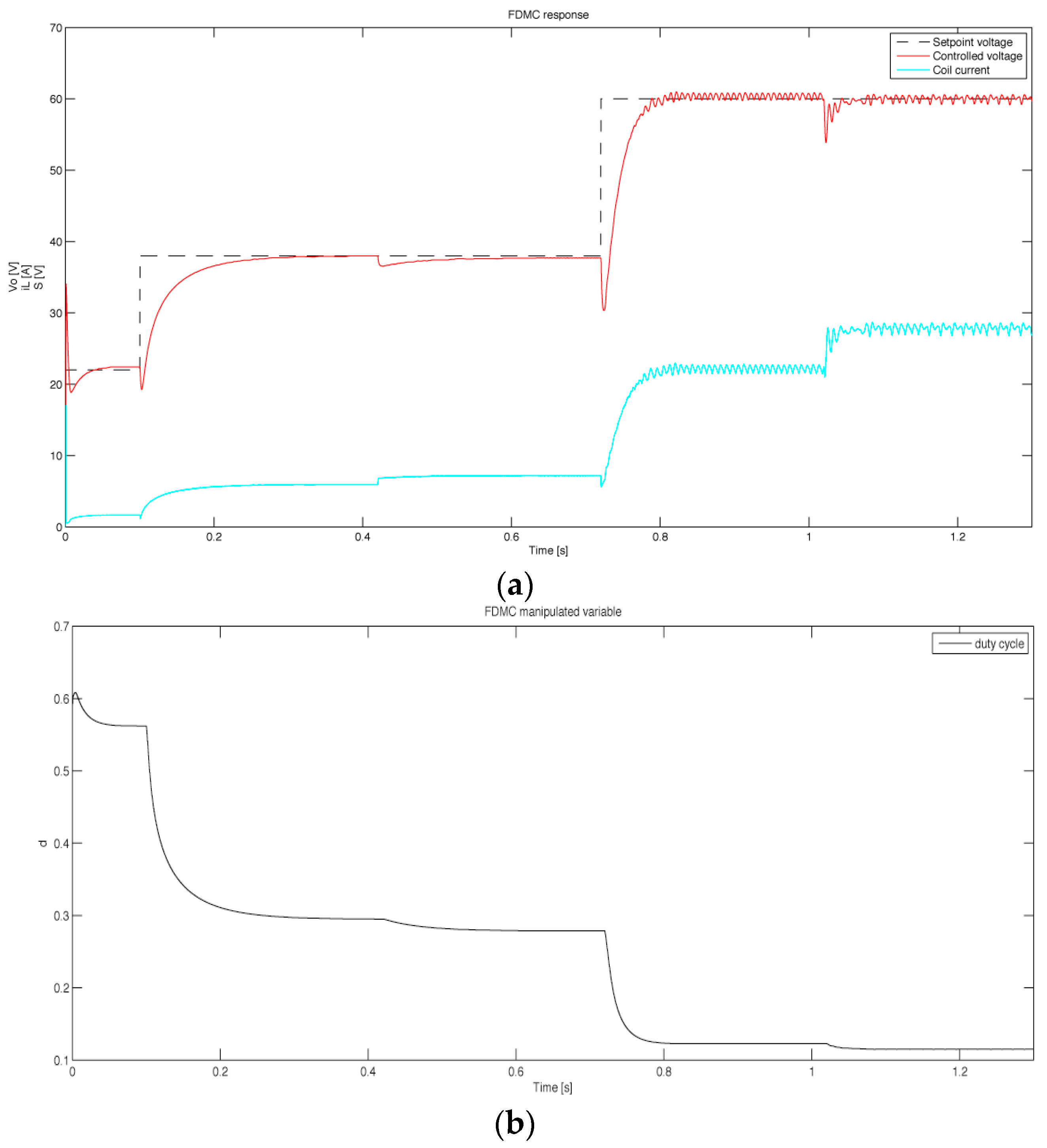
Figure 4, the FGPC responses are significantly slower and have a slightly worse mean square relative error (MSRE) in comparison with the FPFC. We see that even the second-order filter integrated into the prediction model and filtering the model output did not significantly improve the steady state stability, but it reduces the aggressiveness in the response. The small, steady-state chattering in the last two changes of system parameters assign the border of the controller’s robustness. It is well-suppressed by the adaptive controller’s control signal suppression factor. Similarly, the FDMC simulation in
Figure 6 presents the slightly faster response in the transitions and a worse MSRE, but in
Section 2, it is explained that it has less of a processing time burden due to the absence of the model output filter.
From the results, the similarities related to the aggressiveness in the transitions and the accuracy in the steady-state of the applied FMPC methods are noticeable. The best performance is experienced with the FPFC in
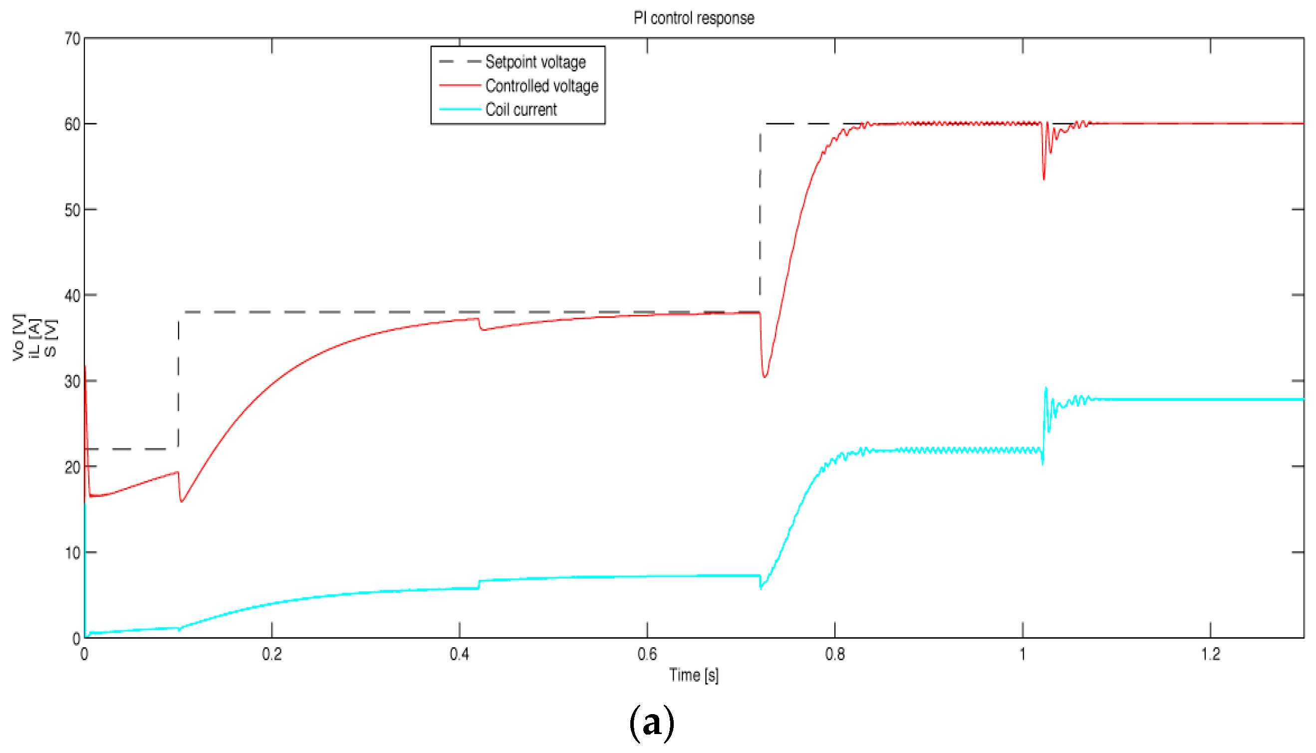
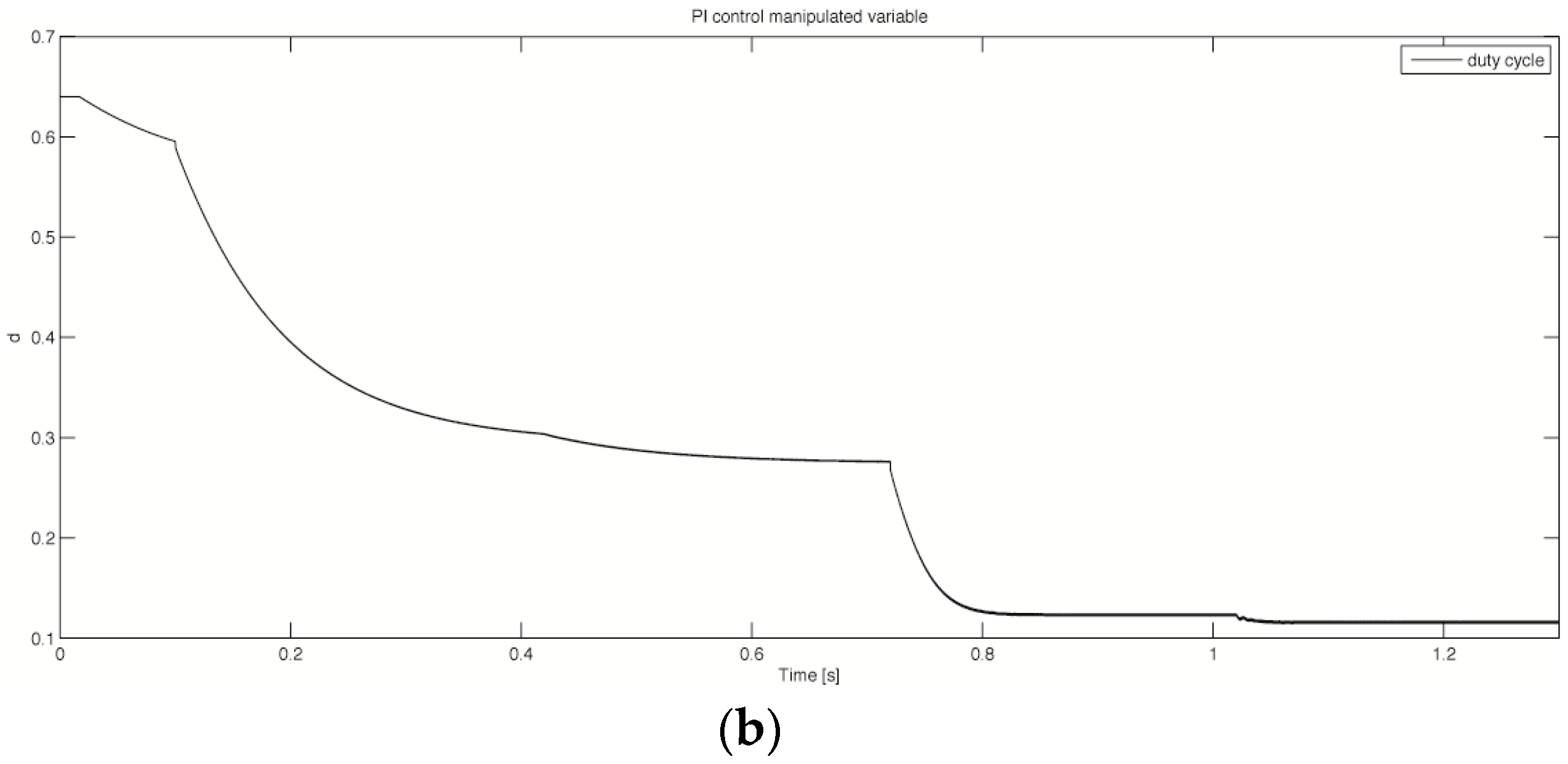
Figure 3, and other methods can be compared to that reference. Closer to the performance of the FPFC is the FDMC. The FGPC has been found to be a bit coarser in the steady state, but on some occasions, such as a system start, it is faster in the response. As expected, the optimized PI controller in
Figure 6 is slower in transitions, especially for the operating points far from the center of the performed optimization for the time periods in which the lower system gains have been experienced.
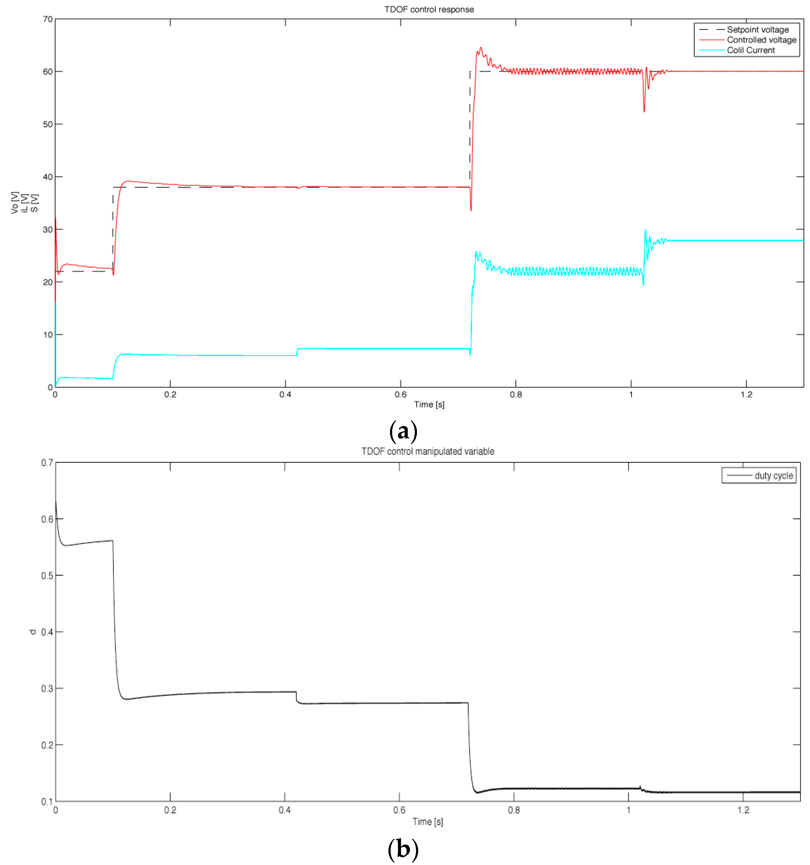
Different from the aforementioned, the TDOF methodology that is presented in
Figure 7 performs as the fastest in transitions, but during that particular time, the control algorithm cannot attenuate the gradient of change, and on some occasions, it violates the reference point. This scenario is initiated by the error of the identified steady state, which is filtered out by the receding horizon strategy in other FMPCs. In contrast, the TDOF algorithm will certainly demand significantly less processor time of execution. From that point of view, the optimized PI controller will use the shortest time of execution, but it is not the robust solution, and in some occasions, it cannot reach the reference value before another is selected (see
Figure 6).
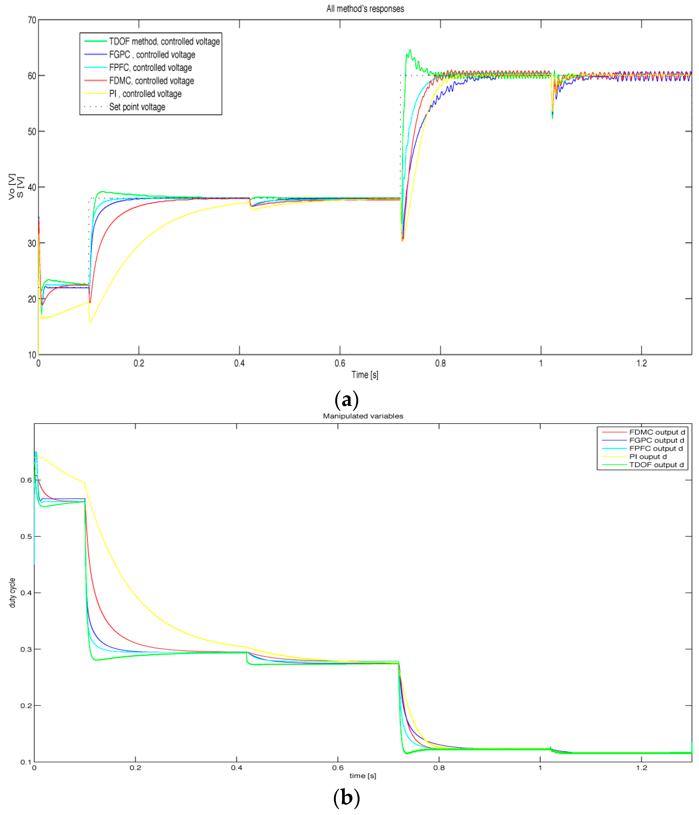
Figure 8 presents all methods together and additionally simplifies the comparison.
The overall comparison is quantified by the time of response and the MSRE that can be seen in
Table 1.
The above successful results led to the selection of the FPFC method as the most favored and comprehensive solution to be applied in the experimental test of the real DC-DC boost converter.
Table 2 presents the controller’s scores related to the assigned objectives in
Section 1.
Referring [
4], our experimental results prove the assigned objectives mentioned in the Introduction and in
Section 2 for the FPFC as the controller with the highest score.
4. Conclusions
The primary objective of this article was the new control methodology in the direction of implementing the most recently developed strategies for systems that are physically small, but complex in their behavior. That task required the fundamental decomposition of the problem and the learning of the most basic system’s behavior. Differently from here, most of the known methods performed on this particular problem employ the analytical methodology in forming the model-based solution [
5]. In this study, the model is identified with fuzzy logic. Additionally to widely known objectives, the developed modeling allows the forming of control solutions that conciliate the method’s complexity with applicability to the physical processes.
The novel controllers presented are developed with the intention of reducing the online processing complexity. This intention guides the development of two different control methodologies. Both of the control methodologies utilize model-based predictive control. In the case of TDOF control, the problem was decomposed in a way to compensate for the main drawback of the numerically optimized linear controller, which is recognized for its robustness for a wider range of the process parameters’ change.
The transition period in TDOF methodology is fast, but it sometimes overshoots the reference point, depending on the positivity of the system/model error at that operating point. To synthesize the solution that is considered to be a dynamic model-based prediction, and to rectify the overshoots, a fuzzy model-based MPC solution is derived. In this study, it is shown that for the reasonable longer processing time, the FMPC successfully follows the aggressiveness of the TDOF controller and the contemporary reference model. Furthermore, the modern predictive control methodology here presented has suboptimal control over the complete transition period and the smooth, steady state of the system. Therefore, in general, the presented FMPCs provide the MPC methodologies that apply to the fast response systems.
Further research will go in the direction of implementing these methodologies into the more complex SAS, as well as continuing to implement the qualitative mathematical theory in designing and exploring the new control methodologies.


