Article

An Analytical Subdomain Model of Torque Dense Halbach Array Motors

1
Department of Mechanical Engineering, University of Houston, Houston, TX 77004, USA
2
Technology Development, NOV Corporate Engineering, Houston, TX 77036, USA
*
Author to whom correspondence should be addressed.
Energies 2018, 11(12), 3254; https://doi.org/10.3390/en11123254
Submission received: 30 October 2018 / Revised: 19 November 2018 / Accepted: 20 November 2018 / Published: 22 November 2018
(This article belongs to the Special Issue Energy Efficiency in Electric Devices, Machines and Drives)

Abstract

:
A two-dimensional mathematical model estimating the torque of a Halbach Array surface permanent magnet (SPM) motor with a non-overlapping winding layout is developed. The magnetic field domain for the two-dimensional (2-D) motor model is divided into five regions: slots, slot openings, air gap, rotor magnets and rotor back iron. Applying the separation of variable method, an expression of magnetic vector potential distribution can be represented as Fourier series. By considering the interface and boundary conditions connecting the proposed regions, the Fourier series constants are determined. The proposed model offers a computationally efficient approach to analyze SPM motor designs including those having a Halbach Array. Since the tooth-tip and slots parameters are included in the model, the electromagnetic performance of an SPM motor, described using the cogging torque, back-EMF and electromagnetic torque, can be calculated as function of the slots and tooth-tips effects. The proposed analytical predictions are compared with results obtained from finite-element analysis. Finally, a performance comparison between a conventional and Halbach Array SPM motor is performed.

1. Introduction

Permanent magnet (PM) motors have been deployed on machine electromechanical machinery for decades, owing to their reliable performance, electrical stability and durability [1]. These motors have been the industry gold standard, finding their way into both rotary and linear applications. PM machines are largely classified into three categories based on the placement of permanent magnets, namely the: (i) inset PM machine, (ii) internal PM machine and (iii) surface PM machine. To improve the electromagnetic torque density, investigations have focused on improving permanent magnet performance within the rotor. Recently, motor designs have moved from samaraium cobalt (SmCo) to neodymium iron boron (NdFeB). While NdFeB has higher remanence, achieving torque enhancements, such embodiments suffer from less coercivity and are prone to demagnetization. As a result, motor designs have created intricate ways to remove heat from this class of machines whereby NdFeB is applicable. Different laminate materials have also been investigated with the use of water-cooling and different magnet arrangements to improve performance. All these advancements are valuable and have improved the torque density of rotating machines. Presented in this manuscript is the application of these integrated principles to discover new magnet arrangements based on the Halbach Array.
The Halbach Array was originally discovered in the 1970s and replicated by Hans Halbach in the mid-1980s. This new magnetic array arrangement oriented the magnet poles such that the flux is magnified in a specific direction while limiting the flux in the opposite direction. Despite concentrating the magnetic flux is a desired direction; a Halbach Array may not necessarily improvement torque density. In fact, it is possible to create an adverse effect on torque density. For that reason and the associated manufacturing costs, Halbach Arrays have not found a niche in electric motor applications.
Halbach Array magnetization was proposed in many applications [2] and has become increasingly popular [1] with various topologies and applications: radial [3] and axial-field [4], slotted and slotless [5,6,7,8], tubular and planar for rotary [9,10] or linear [11] machines. Halbach Array configurations exhibit several attractive features including a sinusoidal field distribution in air gap that results in a minimal cogging torque and a more sinusoidal back EMF waveform [12]. Thus, using Halbach Array SPM eliminates the conventional design techniques such as skewing of the stator/rotor [13], optimization of the magnet pole-arc [14] and distributed stator windings [15]. The Halbach Array magnets configuration generates a steady magnetic field in the active region which yields many benefits including: (i) compact form with high torque density up to 30%, (ii) less weight due to less rotor back iron volume and (iii) lower rotor inertia [16]. Adopting a Halbach Array does not always assure torque improvement in motors. To improve torque performance, the magnetization pattern of the PMs in the array must be cautiously designed. Furthermore, the theoretical electro-magnetic modeling is very advantageous to improve the control applications [17,18]. Torque-dense motor design optimization requires a computationally efficient mathematical model parameterized by design parameters including geometric, electric and magnetic motor properties. Many studies have been dedicated to the analytical calculation of the electromagnetic devices and Halbach Array machines [19].
Liu et. al proposed a method to divide and establish nonlinear adaptive lumped equivalent magnetic circuit (LPMC) that included the slot effect [20]. Using Kirchhoff’s Laws, the model predicts the electromagnetic performance through an iterative process. The accuracy of these predictions were found to be lower than that of the subdomain analytical solutions [21]. In addition, transfer relations, such as Melcher’s method, analytically predict the electromagnetic characteristics of a tubular linear actuator with Halbach Array [22]. Their work derives the generalized vector potentials due to permanent magnets and single-phase winding current using transfer relations. However, the influences of stator slot and tooth tips effects were neglected. Shen et al. applied the subdomain method for Halbach Array slotless machine [3]. The motor performance is derived through a scalar potential calculation over three regions: rotor back iron, permanent magnets and air gap. The major limitation of this approach is that the model does not account for the slot and tooth-tips effects for different winding layouts.
A 2-D model for SPM machines was developed in for conventional permanent magnets magnetizations [23]. A subdomain model incorporating the influence of slot and tooth-tips was developed to predict the armature reaction field for conventional SPM [24]. This particular model is valid for Halbach Array magnetization. Broadening the class of Halbach Array magnetic parameterization, a slotless motor model was developed having different pole-arc [25,26]. This feature is employed in the developed model by introducing the so-called magnet ratio parameter that improved the electromagnetic performance over an equal pole-arc machine (conventional SPM).
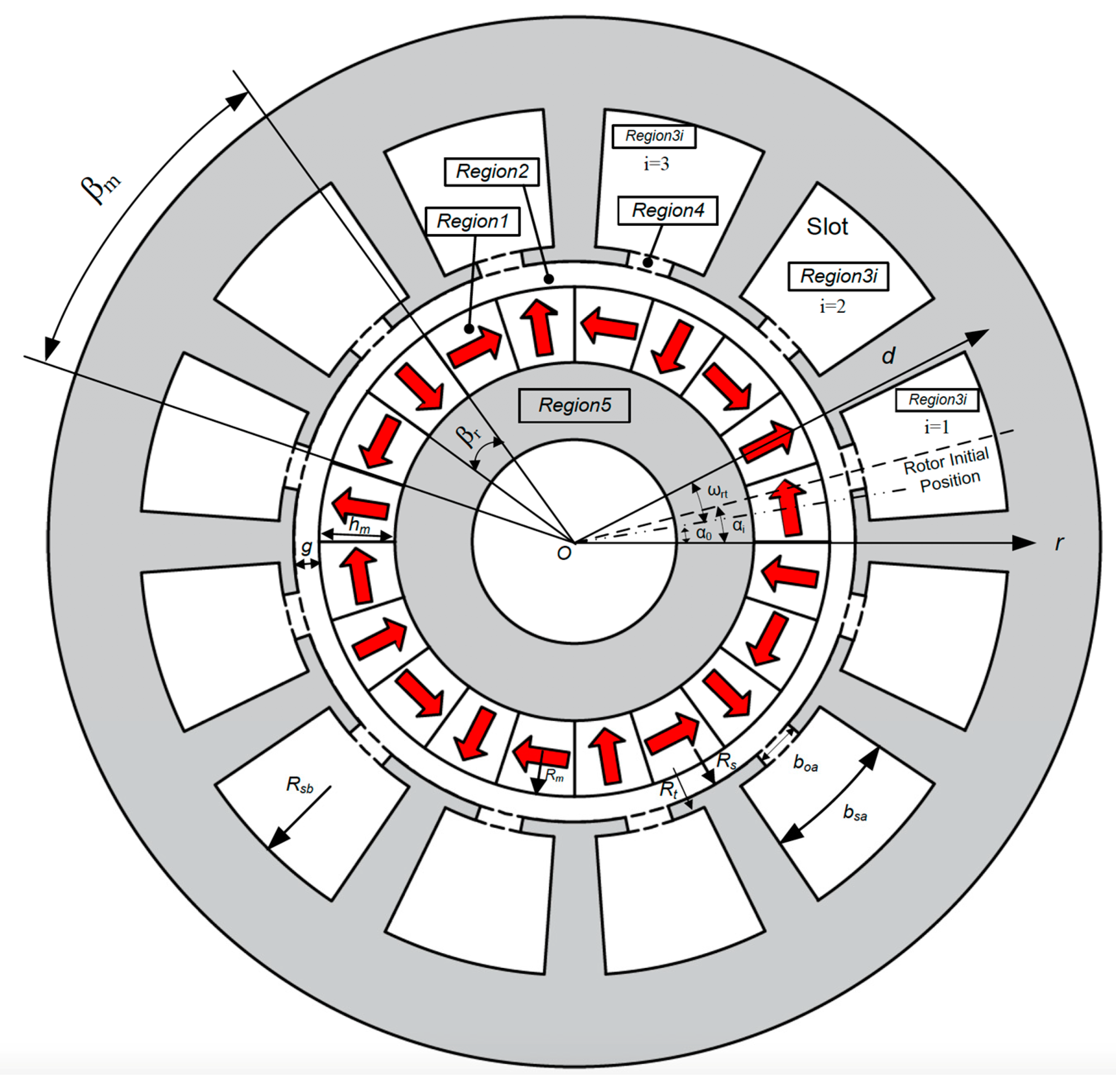
The contribution of this paper is the development of a subdomain motor model for a slotted Halbach Array SPM motor incorporating both slot and tooth-tip effects. Torque maximization is accomplished by optimizing Halbach Array magnets configuration through the introduction of the magnet ratio. The objective is to predict the electromagnetic characteristics quantified by cogging torque, back-EMF and electromagnetic torque. The motor embodiment is divided into five physical regions; rotor back iron, magnets region, air-gap, tooth opening and slot region. Maxwell Equations are developed for each subdomain vector potential from which the flux density is derived. The governing equations for vector potential distribution are solved using the Fourier method. This solution provides the vector potential in each subdomain expressed as a Fourier series that is a function of unknown constants. The boundary conditions are emphasized at this stage, the vector potential and magnetic field should be continuous at the interface between two subdomains. A resultant linear system of analytical independent equations relating all the unknown constants is formulated. Then, the permanent magnet flux linkage is computed as an integral of the normal flux density along the stator bore. The coil is considered as either a punctual source of current [27,28] or a current sheet over the slot opening [29] where the slotting effect is approximated. The flux linkage is calculated by an integral of vector potential over the slot area. The flux passing through the conductors is accounted for using this method. Finally, having the flux linkage, the back-EMF and electromagnetic torque will be derived.
The remaining of the paper is organized as follows. In Section 2, the analytical field modeling and derivation with the subdomain method is developed. In Section 3, the electromagnetic performance, including back-EMF waveforms, electromagnetic torque and cogging torque are compared with the FE results, and the impact of magnet ratio on torque improvement is analyzed. Thermal analysis is carried out in Section 4 and conclusions are provided in Section 5.

2. Methods and Mathematical Modeling

For the purposes of model development, consider the schematic view of a 10-pole/12-slot PM machine Figure 1. The motor has a two-segmented Halbach Array with non-overlapping windings. The 2-D mathematical model developed in this section is based on the following assumptions: (1) infinite permeable iron materials, (2) negligible end effect, (3) linear demagnetization characteristic and full magnetization in the direction of magnetization, (4) non-conductive stator/rotor laminations, and (5) the gaps between magnets have the same constant relative permeability as magnets [23].

2.1. Vector Potential Distribution

The magnetic flux density can be expressed as [19]:
B = μ 0 ( μ r H + M ) .
and μr (H/m) is the relative permeability, μ0 (H/m) is the permeability of vacuum, M (A/m) is the magnetization, and H [A/m] is the magnetic field intensity. The vector potential can be expressed using the magnetic field as:
B = 2 A .
Substituting B from (1) into (2) gives:
2 A = μ 0 μ r × H μ 0 × M = μ 0 μ r J μ 0 × M
where J (A/m2) is the current density. Provided the eddy current does not influence the field distribution, the vector potential equation in the magnets becomes:
2 A = μ 0 × M .
The 2-D field vector potential has only one component along the z-axis that must satisfy the following equations based on (4):
1)
Magnet Region:
2 A z 1 r 2 + 1 r A z 1 r + 1 r 2 2 A z 1 2 α 2 = μ 0 × M = μ 0 r ( M α M r α )
2)
Slot Region:
2 A z 3 r 2 + 1 r A z 3 r + 1 r 2 2 A z 3 2 α 2 = μ 0 J
3)
Air-Gap, Slot Opening and Rotor Back Iron Regions:
2 A z 2 , 4 , 5 r 2 + 1 r A z 2 , 4 , 5 r + 1 r 2 2 A z 2 , 4 , 5 2 α 2 = 0
where r is the radial position and α is the circumferential position where the d-axis shown in Figure 1 is the origin and anti-clockwise is the forward direction. The radial and circumferential components M r Figure 2 and M α Figure 3 are:
M r = k = 1 , 3 , 5 , M r k cos ( k p α )
and:
M α = k = 1 , 3 , 5 , M α k sin ( k p α ) .
All the series expansions in this paper are infinite but there will be an introduction of finite harmonic orders in Section 3 for the sake of calculations and matrices inversions. Using the Halbach Array representation, the Fourier series coefficients are defined as:
M r k = 2 B r μ 0 R m p sin ( R m p k π 2 ) R m p k π 2
and:
M α k = 2 B r μ 0 R m p cos ( R m p k π 2 ) R m p k π 2
where Br is residual flux density of magnet and R m p is the magnet ratio defined as the ratio of the pole arc β r to pole pitch of a single pole β m (Figure 4):
R m p = β r β m
The current density, J, can be expressed as:
J = J i 0 + n J i n cos [ E n ( α + b s a 2 α i ) ] ,
J i 0 = d ( J i 1 + J i 2 ) b s a ,
J i n = 2 n π ( J i 1 + J i 2 cos ( n π ) ) sin ( n π d / b s a )
and:
E n = n π b s a .
where b s a 2 α α i + b s a 2 , and α i and b s a are the slot position and the slot width angle respectively. Thus, Equation (5) becomes:
2 A z 1 r 2 + 1 r A z 1 r + 1 r 2 2 A z 1 2 α 2 = μ 0 r ( k [ ( M α c k k M r s k ) cos ( k α ) + ( M α s k + k M r c k ) sin ( k α ) ] ) .
The general solution for Equation (17) is:
A z 1 = k [ A 1 ( r R m ) k + B 1 ( r R r ) k + μ 0 r k 2 1 ( M α c k k M r s k ) ] cos ( k α ) + k [ C 1 ( r R m ) k + D 1 ( r R r ) k + μ 0 r k 2 1 ( M α s k + k M r c k ) ] sin ( k α )
where A1, B1, C1 and D1 are coefficients will be determined later and Rr and Rm are the radii of rotor back iron and magnet surfaces respectively.
The general solution for (7), the vector field in the air-gap, is:
A z 2 = k [ A 2 ( r R s ) k + B 2 ( r R m ) k ] cos ( k α ) + k [ C 2 ( r R s ) k + D 2 ( r R m ) k ] sin ( k α )
where A2, B2, C2 and D2 are coefficients to be determined and Rs is the radius of inner stator surface. For non-overlapping windings, the general solution of (6), the vector field in the ith slot, can be derived by incorporating the boundary condition along the slot bottom on the surface of infinite permeable lamination when the circumferential component flux density is zero, namely:
A z 3 i = A 0 + n A n cos [ E n ( α + b s a 2 α i ) ]
where:
A 0 = μ 0 J i 0 4 ( 2 R s b 2 ln ( r ) r 2 ) + Q 3 i ,
A n = D 3 i [ G 3 ( r R s b ) E n + ( r R t ) E n ] + μ 0 J i n E n 2 4 [ r 2 2 R s b 2 E n ( r R s b ) E n ]
And:
G 3 = ( R t R s b ) E n
Q3i and D3i are coefficients to be derived using regions interactions. In the ith slot opening, the vector field is derived by considering the boundary condition on both sides of the slot opening:
A z 4 i = D ln ( r ) + Q 4 i + m [ C 4 i ( r R t ) F m + D 4 i ( r R s ) F m ] cos ( F m ( α + b o a 2 α i ) )
where D, Q4i, C4i and D4i are unknown coefficients to be determined, boa is the slot opening width and Fm is defined as follows:
F m = m π b o a .
The general solution for the vector field in the rotor back iron is:
A z 5 = k [ A 5 ( r R r ) k + B 5 ( r R 0 ) k ] cos ( k α ) + k [ C 5 ( r R r ) k + D 5 ( r R 0 ) k ] sin ( k α )
where A5, B5, C5 and D5 are coefficients to be determined later, R0 is the radius of inner rotor back iron surface.
The unknown coefficients in the expressions of vector potentials (18)–(26) are determined by applying the continuations of normal flux density and circumferential vector potential between subdomains. The details derivations are presented in the following section.

2.2. Boundary Conditions

The radial and circumferential components of flux density is calculated from the vector potential distribution as:
B r = 1 r A z α   and   B α = A z r .
In the magnet region, the magnetic flux density is:
B = μ 0 μ r H + μ 0 M .
while it is expressed in the rotor back iron, air gap, slot and slot opening as:
B = μ 0 H .

2.2.1. Interface Between Air and Rotor Back Iron

Applying (29) to calculate the circumferential magnetic field intensity H5α in rotor back iron, the boundary condition on the surface requires:
H 5 α | r = R 0 = 1 μ 0 μ r B 5 α | r = R 0 = 0 .
Based on (26) and (27), B 5 α expression is calculated and then applied in (30) which leads to the following equations:
{ B 5 = G 5 A 5 D 5 = G 5 C 5
where:
G 5 = ( R 0 R r ) k .

2.2.2. Interface Between Rotor Back Iron and Halbach Permanent Magnets

The first boundary condition in this surface requires that the circumferential magnetic field intensity is continuous between the rotor back iron and Halbach Array permanent magnets giving:
H 5 α | r = R r = H 1 α | r = R r .
Referring to (28) H1α is calculated as:
H 1 α = 1 μ r ( B 1 α μ 0 M α )
substituting (34) into (33) gives the expressions:
{ A 1 G 1 B 1 + A 5 ( G 5 2 1 ) = μ 0 R r k 2 1 ( M r s k k M α c k ) C 1 G 1 D 1 + C 5 ( G 5 2 1 ) = μ 0 R r k 2 1 ( M r c k + k M α s k ) .
The second boundary condition is that the normal flux density is continuous between rotor back iron and Halbach Array permanent magnets. B5r is derived from Equations (27) and (29) while B1r is calculated from Equations (27) and (28):
B 5 r | r = R r = B 1 r | r = R r
leading to:
{ A 1 G 1 + B 1 A 5 ( G 5 2 + 1 ) = μ 0 R r k 2 1 ( k M r s k M α c k ) C 1 G 1 + D 1 C 5 ( G 5 2 + 1 ) = μ 0 R r k 2 1 ( k M r c k + M α s k ) .

2.2.3. Interface Between Air Gap and Halbach Permanent Magnets

Firstly, the circumferential magnetic field intensity is continuous between the air gap and the Halbach Array permanent magnets:
H 1 α | r = R m = H 2 α | r = R m .
Referring to (29), H is calculated as:
H 2 α = B 2 α μ 0 .
Substituting (39) into (38) and given H1α from (34), we conclude:
{ A 1 + B 1 G 1 + μ r A 2 G 2 μ r B 2 = μ 0 R m k 2 1 ( k M α c k M r s k ) C 1 + D 1 G 1 + μ r C 2 G 2 μ r B 2 = μ 0 R m k 2 1 ( M r c k + k M α s k ) .
Secondly, the normal flux density is continuous between the air gap and the Halbach Array permanent magnets:
B 2 r | r = R m = B 1 r | r = R m
from which the following expressions can be derived:
{ A 1 + B 1 G 1 B 2 A 2 G 2 = μ 0 R m k 2 1 ( k M r s k M α c k ) C 1 + D 1 G 1 D 2 2 C 2 G 2 = μ 0 R m k 2 1 ( k M r c k + M α s k ) .

2.2.4. Interface Between Air Gap and Slot Opening

Based on (24) and (27), the circumferential component flux density within the slot opening:
B 4 i α = D r m F m R s [ C 4 i ( R s R t ) ( r R t ) F m 1 D 4 i ( r R s ) F m 1 ] cos ( F m ( α + b o a 2 α i ) ) .
Since the stator core material is infinitely permeable which make the circumferential component flux density B along the stator bore outside the slot opening equal to zero. Along the stator bore, the circumferential component flux density is expressed as [23]:
B s α = k [ C s cos ( k α ) + D s sin ( k α ) ]
where:
C s = i m ( F m R s ( C 4 i G 4 D 4 i ) ) η i + i ( D R s ) η i 0 ,
D s = i m ( F m R s ( C 4 i G 4 D 4 i ) ) ξ i + i ( D R s ) ξ i 0 ,
η i ( m , k ) = k π ( F m 2 k 2 ) [ cos ( m π ) sin ( k α i + k b o a / 2 ) sin ( k α i k b o a / 2 ) ] ,
ξ i ( m , k ) = k π ( F m 2 k 2 ) [ cos ( m π ) cos ( k α i + k b o a / 2 ) cos ( k α i k b o a / 2 ) ] ,
η i 0 ( k ) = 2 sin ( k b o a / 2 ) cos ( k α i ) k π
and:
ξ i 0 ( k ) = 2 sin ( k b o a / 2 ) sin ( k α i ) k π .
The first boundary condition demands that the circumferential flux density is continuous between the air gap and the slot opening giving:
B 2 α | r = R s = B s α | r = R s .
Having B from (44) and calculating B from (19) and (27), condition (51) leads to:
{ R s C s = k A 2 + k G 2 B 2 R s D s = k C 2 + k G 2 D 2 .
The vector potential distribution within air gap along the stator bore is given as
A s = A z 2 | r = R s = k [ ( A 2 + B 2 G 2 ) cos ( k α ) + ( C 2 + D 2 G 2 ) sin ( k α ) ] .
The vector potential distribution over the slot opening along the stator bore is
A s = ( k ( ( A 2 + B 2 G 2 ) σ i 0 + ( C 2 + D 2 G 2 ) τ i 0 ) ) + m [ ( k ( ( A 2 + B 2 G 2 ) σ i + ( C 2 + D 2 G 2 ) τ i ) ) cos ( F m ( α + b o a / 2 α i ) ) ]
where
σ i 0 = ( π b o a ) η i 0 ( k ) ,
τ i 0 = ( π b o a ) ξ i 0 ( k ) ,
σ i = ( 2 π b o a ) η i ( m , k ) ,
and
τ i = ( 2 π b o a ) ξ i ( m , k ) .
The vector potential distribution within slot opening along the stator bore is
A z 4 i | r = R s = D ln ( R s ) + Q 4 i + m [ C 4 i G 4 + D 4 i ] cos ( F m ( α + b o a 2 α i ) )
where
G 4 = ( R s R t ) F m .
The second boundary condition involves the continuation vector potential for ( α i b s a 2 α α i + b s a 2 ) is
A z 4 i | r = R s = A s
thus
Q 4 i = k [ ( A 2 + B 2 G 2 ) σ i 0 + ( C 2 + D 2 G 2 ) τ i 0 ] D ln ( R s )
and
D 4 i + C 4 i G 4 = k [ ( A 2 + B 2 G 2 ) σ i + ( C 2 + D 2 G 2 ) τ i ] .

2.2.5. Interface Between Slot Opening and the Slot

Along the interface between the slot and the slot opening, the circumferential component of the flux density is derived from (24) and (27) [1]
B 4 i α | r = R t = B 4 i α 0 + m B 4 i α m cos ( F m ( α + b o a / 2 α i ) )
where
B 4 i α 0 = D R t
and
B 4 i α m = F m R t ( C 4 i D 4 i G 4 )
The circumferential flux density in the slot along the outer radius of the slot opening is null since the stator core material is infinitely permeable. This component along Rt is expressed into Fourier series over ( α i b s a 2 α α i + b s a 2 ) as
B 4 i α | r = R t = B 0 + n B n cos ( E n ( α + b s a / 2 α i ) )
where
B 0 = B 4 i α 0 φ e x ,
B n = B 4 i α 0 φ 0 + m B 4 i α m φ ,
φ e x = b o a b s a ,
φ 0 ( n ) = 4 n π cos ( n π / 2 ) sin ( E n b o a / 2 )
and
φ ( m , n ) = 2 b s a E n F m 2 E n 2 [ cos ( m π ) sin ( E n b s a + b o a 2 ) sin ( E n b s a b o a 2 ) ] .
The circumferential flux density in the slot opening along the interface between the slot opening and the slot is
B 3 i α | r = R t = B 3 i α 0 + n B 3 i α n cos ( E n ( α + b s a / 2 α i ) )
where for non-overlapping winding
B 3 i α 0 = μ 0 J i 0 ( R s b 2 R t 2 ) 2 R t
and
B 3 i α n = E n D 3 i ( G 3 2 1 ) R t 2 μ 0 J i n R t ( E n 2 4 ) ( R t 2 R s b 2 G 3 ) .
Applying the continuity of the circumferential component of flux density gives
B 3 i α 0 = B 4 i α 0 φ a
and
B 3 i α n = B 3 i α n φ 0 + m B 4 i α m φ .
From (65), (71), (74) and (76)
D = μ 0 J i 0 ( R s b 2 R t 2 ) 2 ( b s a b o a ) .
The vector potential distribution in the slot along the radius Rt is
A t = A z 3 i | r = R t = A 3 i 0 + n A 3 i n cos [ E n ( α + b s a 2 α i ) ]
where for non-overlapping winding
A 3 i 0 = μ 0 J i 0 ( 2 R s b 2 ln ( R t ) R t 2 ) 4 + Q 3 i
and
A 3 i n = D 3 i ( G 3 2 + 1 ) + μ 0 J i n ( E n 2 4 ) ( R t 2 2 R s b 2 G 3 E n ) .
The same vector potential is expressed over ( α i b s a 2 α α i + b s a 2 )
A t = A 3 t 0 + m A 3 t n cos [ F m ( α + b o a 2 α i ) ]
where
A 3 t 0 = n A 3 i n κ 0 + μ 0 4 J i 0 ( 2 R s b 2 ln ( R t ) R t 2 ) + Q 3 i ,
A 3 t m = n A 3 i n κ ,
κ 0 = ( b s a b o a ) φ 0 ( n )
and
κ = ( b s a b o a ) φ ( m , n ) .
From the vector potential within the slot opening
A z 4 i | r = R t = D ln ( R t ) + Q 4 i + m ( C 4 i + D 4 i G 4 ) cos ( F m ( α + b o a 2 α i ) ) .
Applying the continuity of the vector potential along the interface between the slot opening and the slot
A t = A z 4 i | r = R t .
The following equations can now be developed
Q 3 i = Q 4 i + D ln ( R t ) μ 0 J i 0 4 ( 2 R s b 2 ln ( R t ) R t 2 ) n A 3 i n κ 0
and
C 4 i + D 4 i G 4 = n A 3 i n κ .

2.3. Back EMF and Torque Calculations

From the field solutions generated in the previous subsection, relevant electromagnetic characteristics, such as the flux linkage and the back EMF, are obtained based on the subdomain models. Also developed are expressions for the electromagnetic torque and cogging torque.

2.3.1. Flux Linkage

Flux linkage occurs when a magnetic field interacts with a material such as a magnetic field travels through a coil of wire. The flux linkage from one coil side of an arbitrary winding is calculated from the magnetic vector potential in the general equation for flux linkage. The calculation can be simplified by means of the Stokes integral theorem:
ψ i 1 = L N c A s S B d s = L N c A s S × A d s = L N c A s C A d s = L N c A s α i b s a / 2 α i b s a / 2 + d R t R s b A z 3 i r d r d α
where L is the stack length of the motor, As is the area of one coil side and Nc is the number of turns per coil.
Based on Az3i in (20) and (91):
ψ i 1 = L N c A s [ Q 0 d + n Q n E n sin ( E n d ) ]
where:
Q 0 = R t R s b A 0 r d r
and:
Q n = R t R s b A n r d r .
Following the same approach, the flux linkage in the other coil side of the same slot is:
ψ i 2 = L N c A s [ Q 0 d n Q n E n sin ( n π E n d ) ] .
The summation of the flux linkages associated with all the coil sides of the corresponding phase results in the total flux linkage of each phase. This calculation includes a connection matrix Sw that represents the winding distribution in the slot:
[ ψ a ψ b ψ c ] = S w ψ c .
Presented is an estimation method for the flux linkage. These results will be used to estimate the phase back-EMF for the Halbach motor.

2.3.2. Back EMF

Based on Lenz’s law, the induced EMF always counters the source of its creation. Here, the source of back-EMF is the rotation of armature. The torque produces rotation of armature. Torque is due to armature current and armature current is created by the supply voltage. Therefore, the ultimate cause of production of the back EMF is the supply voltage. The three-phase back-EMF vector is calculated by the derivative of flux linkage calculated in (96) with respect to time when the motor is in open circuit:
[ E a E b E c ] = ω [ d ψ a d t d ψ b d t d ψ c d t ] .

2.3.3. Electromagnetic and Cogging Torques

The electromagnetic torque is calculated as:
T e m = ( E a I a + E b I b + E c I c ) ω .
Concerning the cogging torque, many methods have been used such as the lateral force [30], complex permeance [31,32] and energy [33,34]. In PM machines, calculating and minimizing the cogging torque is classically evaluated using either the virtual work or Maxwell stress tensor methods. In this development, the Maxwell stress tensor is proposed providing accurate prediction of the air-gap field by way of the subdomain method accounting for tooth-tips. The derivation is based on the open circuit field:
T c = ( L R s 2 μ 0 ) 0 2 π B 2 r B 2 α d α .

3. Results and Model Validation

Validation of the proposed electromagnetic analytical model depends on the modeling accuracy to predict motor torque with slot and tooth tip effects. The proposed validation is based on finite element analysis (FEA) simulations, no experimental results are presented. A Halbach Array machine shown in Figure 1 and a conventional one having both a three-phase 12-slot/10-pole embodiment are adopted to validate the analytical subdomain model developed in this manuscript. In the present validation, the simulation on the conventional and the Halbach Array SPM motors is performed by the help of the commercial FEA software MotorSolve v6.01 (Infolytica Corporation, Montréal, QC, Canada). The motor design parameters applied in the present study are provided in Table 1.
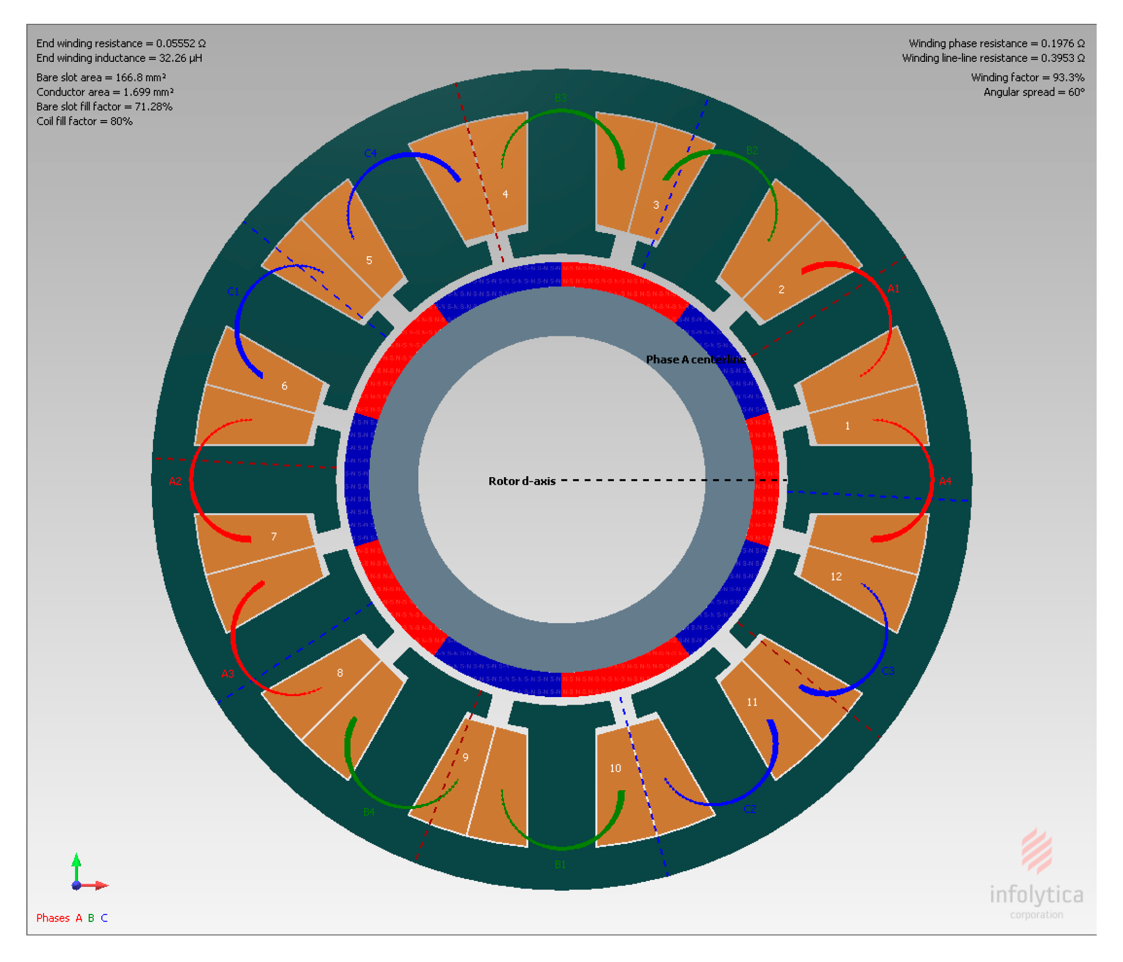
The non-overlapped winding layout is shown in Figure 5. The use of this configuration in SPM motors to meet the optimal flux weakening condition is supported. Therefore, machines made with concentrated windings have shorter end coils, which reduce the total copper ohmic losses, the length and the weight of the machine. In addition, this configuration is chosen to maximize the winding factor of 93.3% with a coil span equal to unity [32]. The results for the Fourier series expansion are computed with a finite number of harmonics for k, m, and n. Generally, the limited number of harmonics is considered in the analytical model to generate suitable results, while the mesh in the FE model must be adjusted before achieving acceptable results. The computation time of the analytical field solutions is dependent from the harmonic numbers (k, m, n), for (100, 50, 50), by way of example, the average calculation time is 14.3 s (with 2.3 GHz CPU) on the MatLab platform. For the Halbach Array magnets configuration, when the magnet ratio 
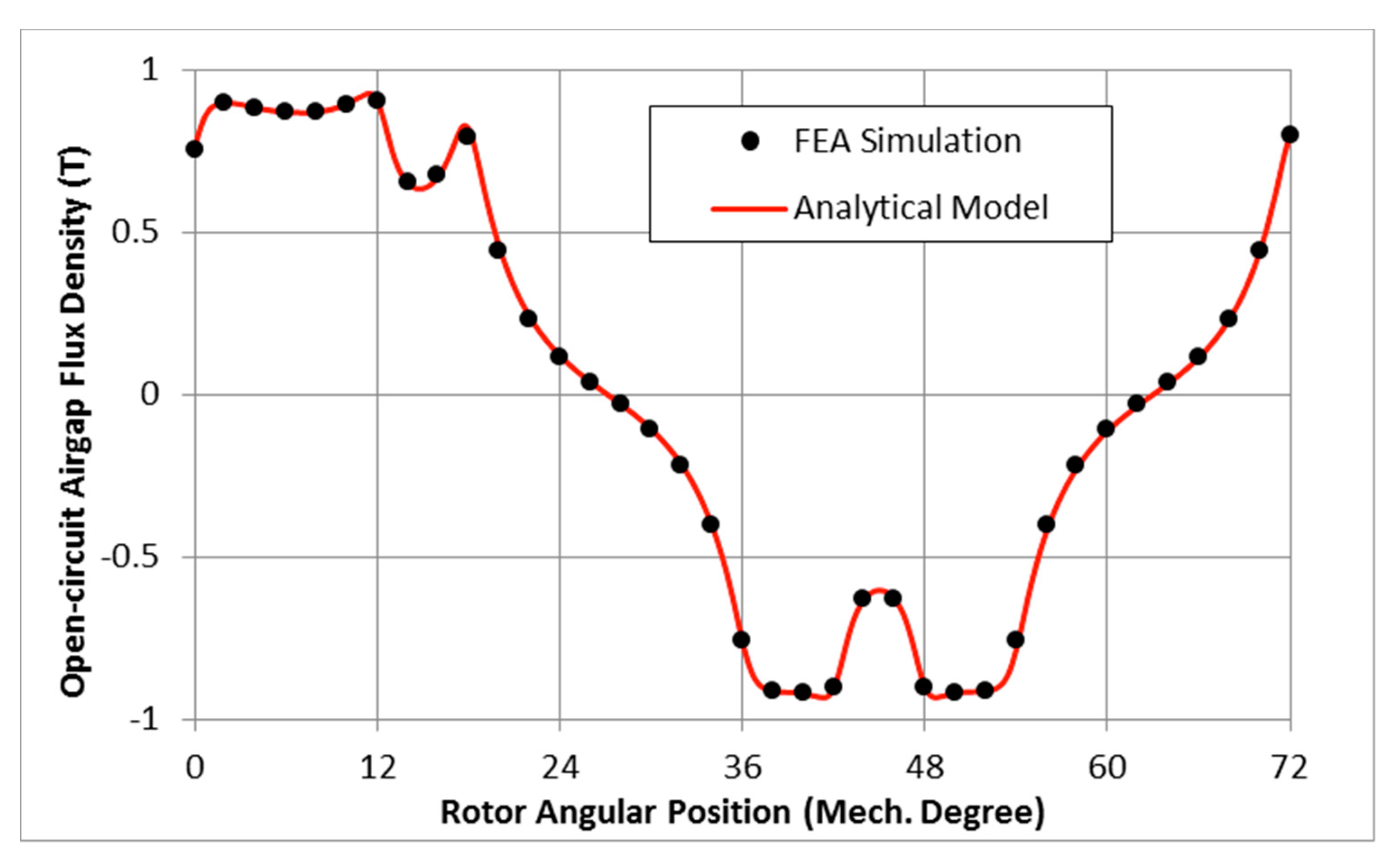
Rmp, equal to 0.5, the predicted 2-D analytical radial flux density and MotorSolve simulation in the centerline of air gap position are presented in Figure 6. The resulting air gap flux density waveform distributions are distorted at the slot-openings showing that the analytical subdomain model is able to capture the slot-openings and tooth tips effects. The proposed model predicts the flux density within the considered five subdomains. MotorSolve only provides the flux density prediction for only the air-gap. The validation of flux density would promote further analysis in the demagnetization withstand ability for different magnet ratio cases and inductance prediction.
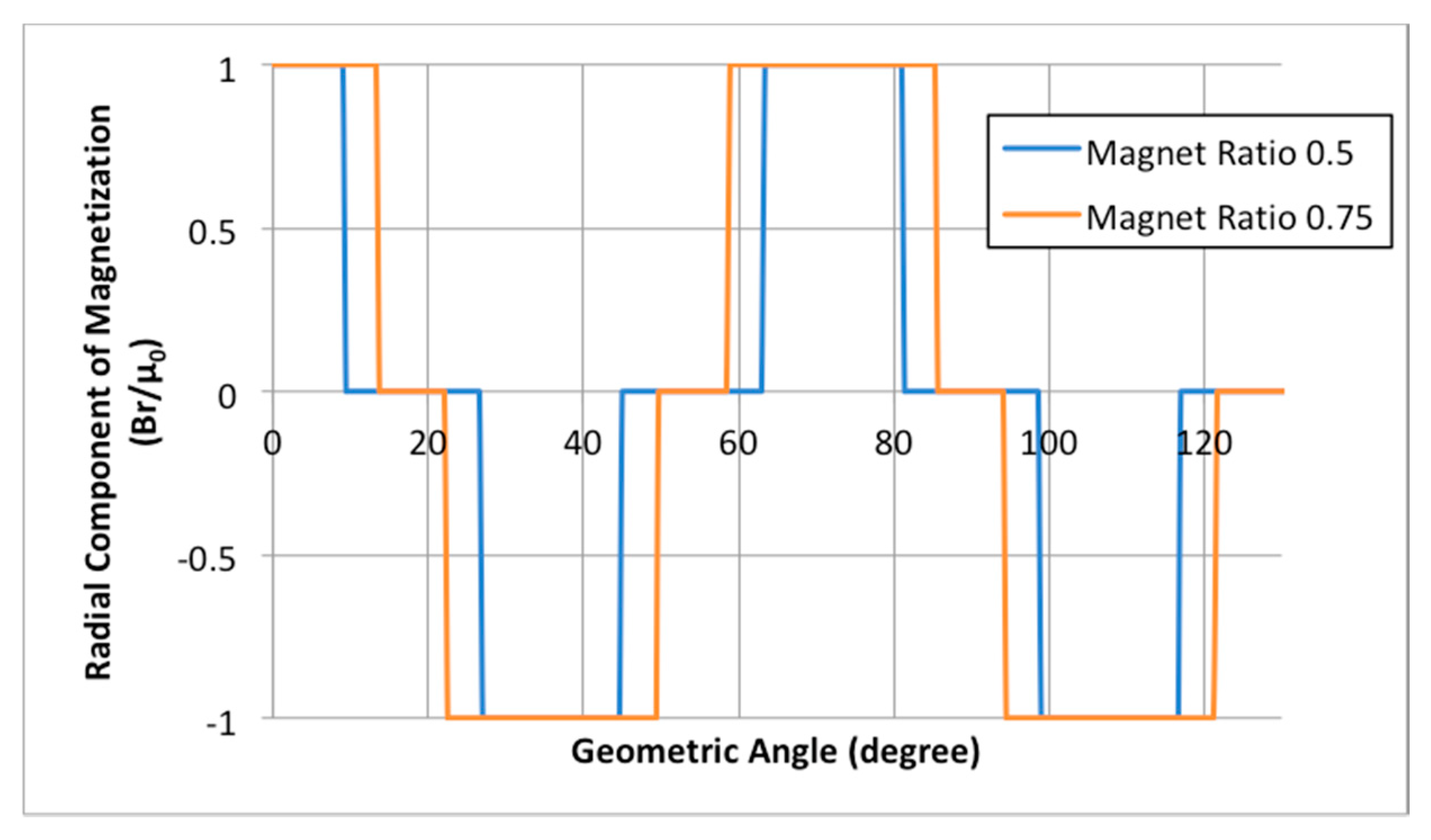
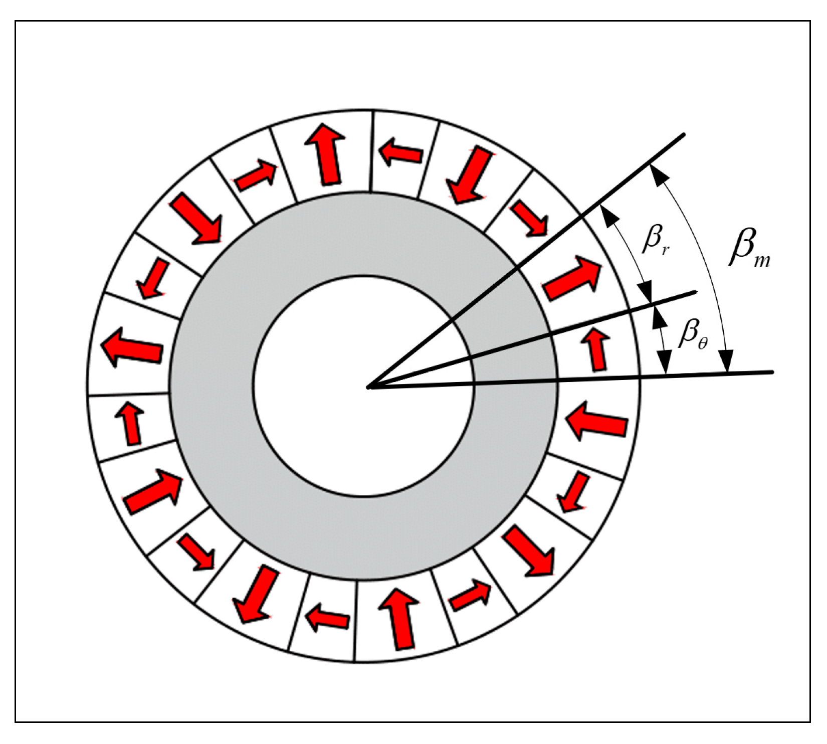
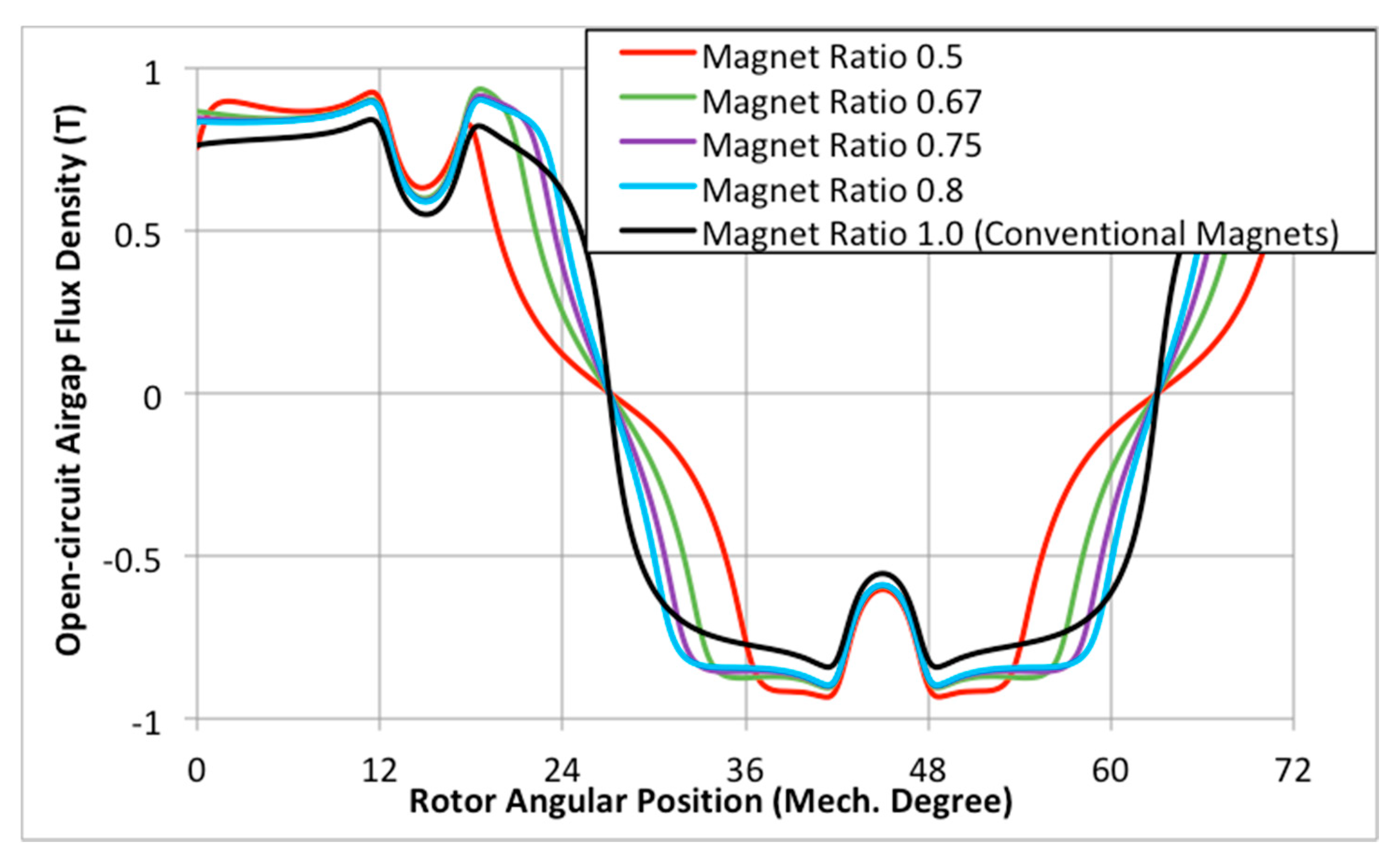
By varying the magnet ratio, the proposed model can predict a variety of magnetization patterns as shown in Figure 7. It should be noted that the conventional SPM magnet has a magnet ratio Rmp equal to unity, while the magnet ratio should be 0.5 for the model shown in Figure 1, when the side and the central magnet segments have the same size. The highest flux density peak value (FDPV) is given by lowest Halbach Array magnet ratio, which is approximately 10% higher than the conventional magnetization. By increasing the magnet ratio, the FDPV decreases and the shape of the flux becomes wider within each pole range. This is because the central magnet with radial magnetization becomes wider as the magnet ratio increases. The air gap flux density waveform reaches its widest and lowest peak amplitude in the magnet ratio of unity.
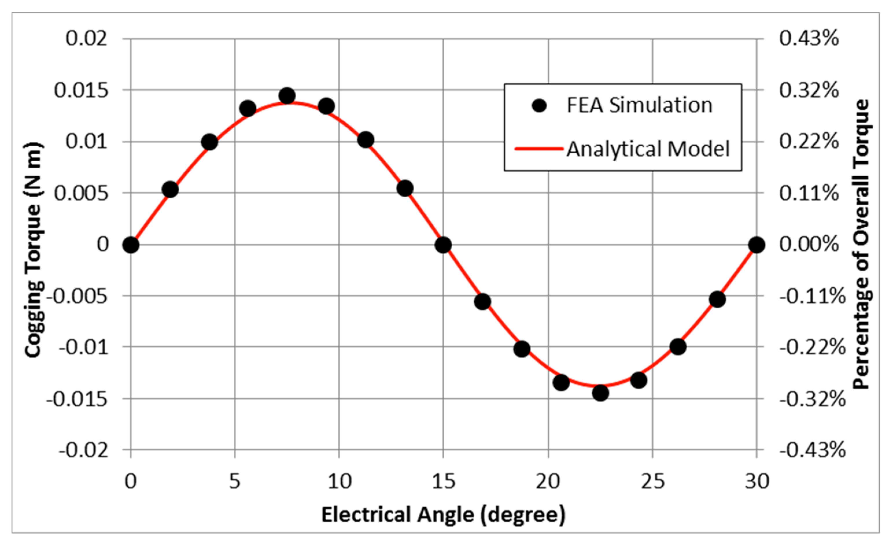
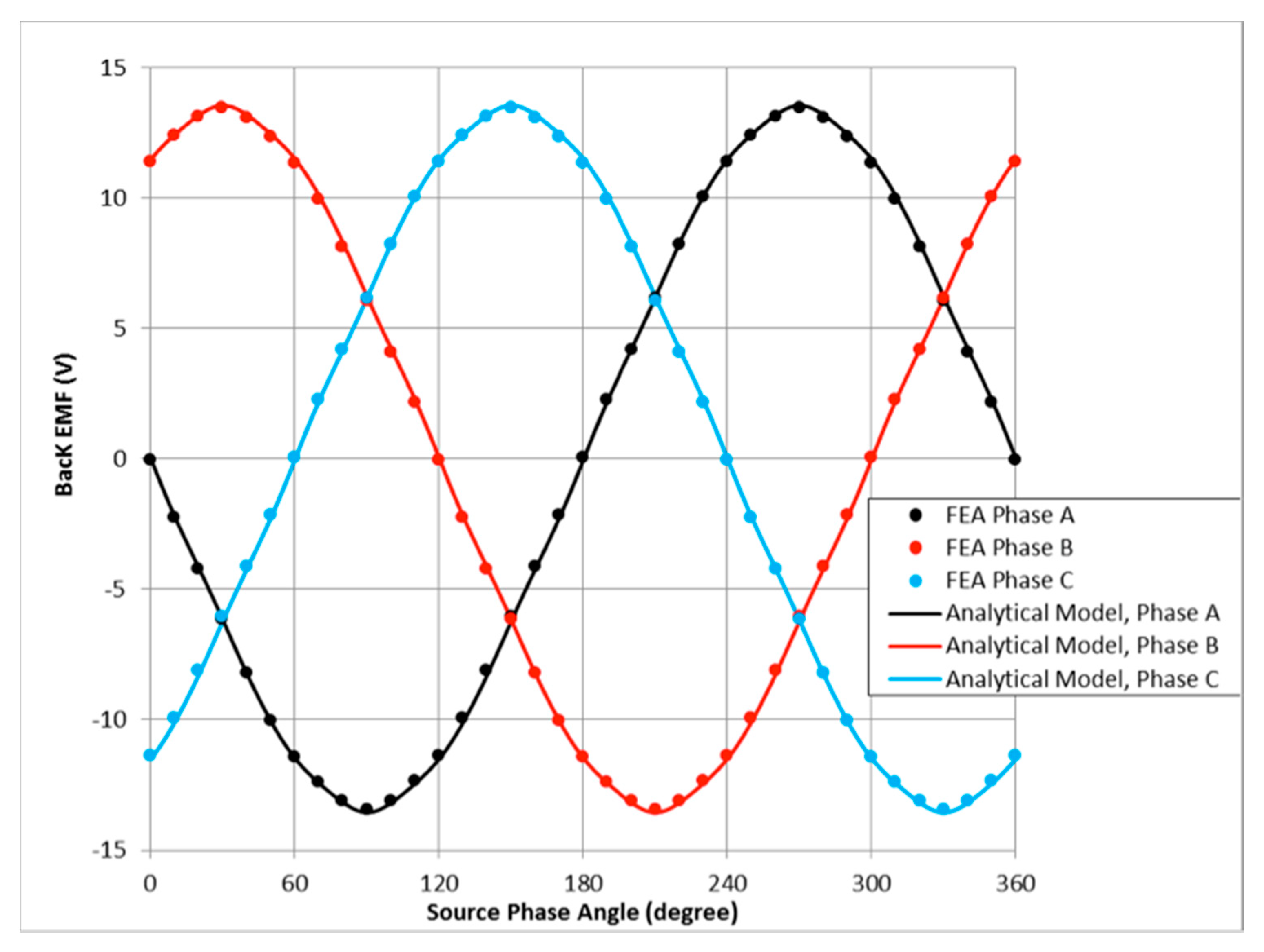
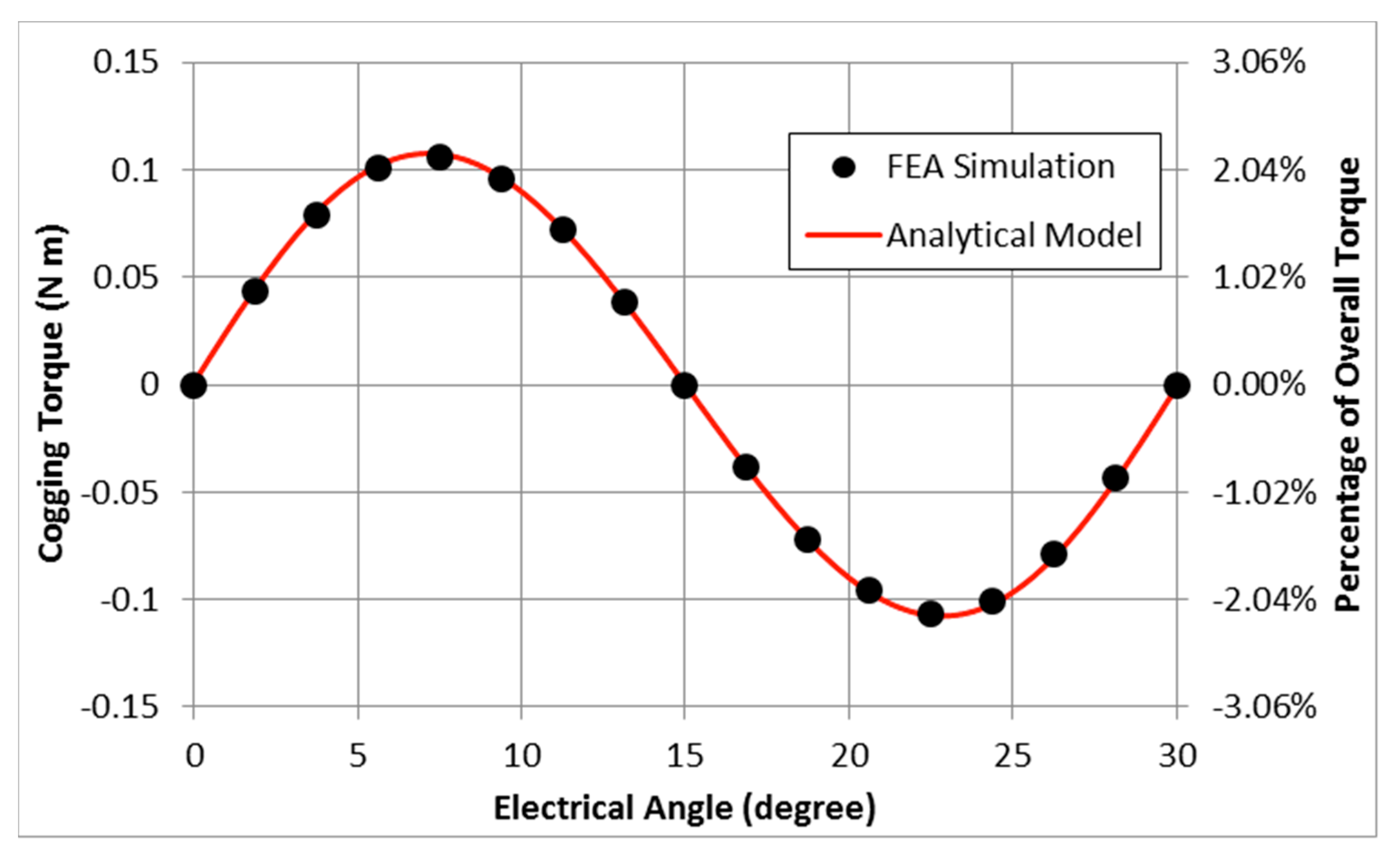
The stator windings are excited with sinusoidal currents with a peak value of 10A. Shown in Figure 8, Figure 9 and Figure 10 are the comparisons between the analytically calculated and FEA simulated waveforms of electromagnetic torque, cogging torque and back-EMF, respectively.
The analytical results provide good agreements with those obtained from FEA simulation. Shown in Figure 11 are the flux lines with different magnet ratio values. The flux lines are densely low in the passive region (rotor back iron) for the magnet ratio 0.5. When increasing the magnet ratio, the FDPV increases to the value of conventional magnet pattern.
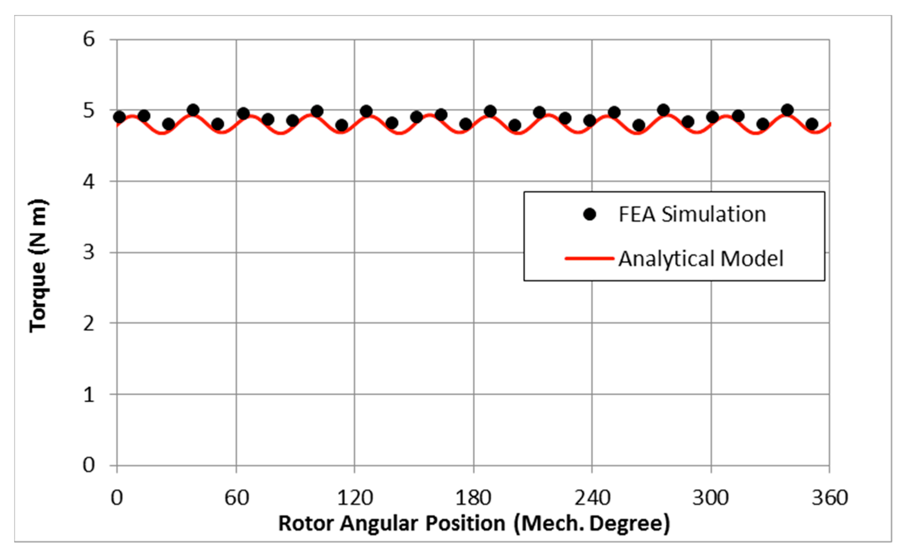
For comparison purposes, the electromagnetic performance for the conventional (non-Halbach) motor design with the same parameters in Table 1 is shown in Figure 12, Figure 13 and Figure 14. All results for the analytical calculations are in agreement with FEA simulations.
The back-EMF for Halbach Array motor is more sinusoidal than conventional surface-mounted permanent magnet motor. As a result, the Halbach Array machine, as shown in Figure 9 (Rmp = 0.5), provides much lower cogging torque (with a peak magnitude of 0.015 Nm) comparing to conventional motor in Figure 13 (with a peak magnitude of 0.11 Nm).
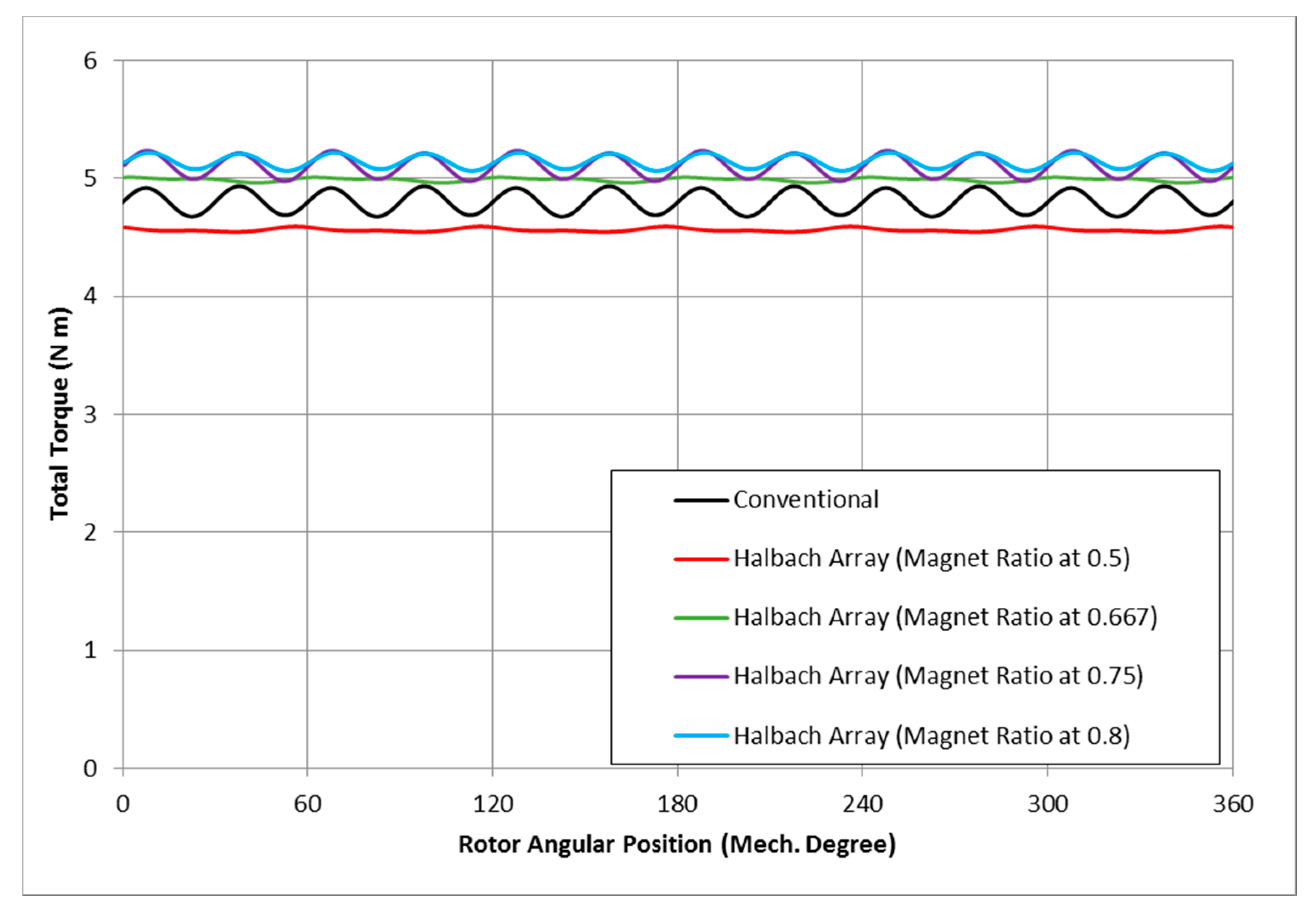
Comparison motor torques among the different machine designs is presented in Figure 15. Among the magnet ratios of 0.5, 0.667, 0.75, 0.8 and 1, the design for 0.8 provides the highest torque, which is approximately 10% higher than the conventional design (Rmp = 1) in this particular configuration while it has reached 25% for other cases. Also note that the design with a magnet ratio of 0.5 actually generates 4.5% less torque comparing to the convention magnet configuration. These results demonstrate that the maximization process of electromagnetic torque is nonlinear with respect to the magnet ratio. Only with an appropriate and optimal magnet ratio can the Halbach Array design provide a higher torque compared to the conventional SPM motor given the same size and supply constraints. From such calculations, it suggests that the PM motor output torque is related to the integration of the half cycle of flux linkage for each coil; and the optimal magnet ratio to maximize the torque requires the maximum integration of this flux linkage for each coil, under the same input conditions [3]:
π 2 3 π 2 ψ c o i l d θ R m p = 0 .

4. Thermal Analysis

In addition to the electromagnetic modeling, a thermal analysis of the reported 10-pole SPM motor is performed using FEA simulation. Such an analysis is to provide illuminated evaluations for the heat generation and its transfer within the motor embodiment during operation. As a result, the temperature distribution within the motor assembly can be predicted. Overheat spots on copper windings or thermal-sensitive electric components are regarded as constraints to the motor embodiment and will be examined. Unless sufficient heat could be removed from the motor assembly, or limited current magnitude would be allowed for necessary cooling to suffice, over-heat or melting would happen in the motor material and cause malfunction of operation, or even bring about safety issues.
In the present study, the thermal analysis and evaluation are performed under the requirements that the maximum temperature within the motor assembly be lower than 180 °C (any spots with a temperature higher than 180 °C will be considered as motor overheat). There are two main sources for the heat generation while a PM motor machine operates, which are often referred as the copper loss and the iron loss. Copper losses are generally the heat losses generated within the copper winding conductor because of its carried electric current, which are proportional to the winding resistance and the square of the current magnitude. Generally, lower current values or winding resistance (e.g., shorter total length or fewer numbers of turns in stator) will reduce the heat caused by the copper loss. Also, the limitation of the total motor weight would require less use of copper in windings, which could minimize its cross-sectional area, increase the conductor resistance and therefore increase heating.
For the iron loss, two mechanisms occur, namely eddy current loss and hysteresis loss. The eddy current loss is produced by relative movement between conductors (stator iron core) and magnetic flux lines. The hysteresis loss is due to reversal of magnetization of stator iron core whenever it is subjected to changing magnetic forces. The iron loss depends on variables such as the thickness of the laminations in the stator, the magnitude of the flux density, the stator iron material resistivity, and most importantly, the frequency at which the motor operates. To use a laminated stator and decrease the thickness of the laminations with electrical insulation from each other could reduce the iron loss.
The modeling of the iron loss power Piron per unit volume of the stator material in this study was performed as:
P i r o n = k e B p 2 f 2 + k e x B p 1.5 f 1.5 + k h B p 2 f
where ke, kex and kh are the coefficients of classical eddy current loss, excess eddy current loss and hysteresis loss, respectively. The variable Bp is the peak flux density in the three-dimensional (3-D) stator domain and f is the motor supply frequency. The coefficients here for iron losses are related to the given stator material properties from manufacturers, and the integration of the iron heat loss within the entire stator body is calculated in FE model using above equation performed in the stator teeth and yoke (back iron) domains.
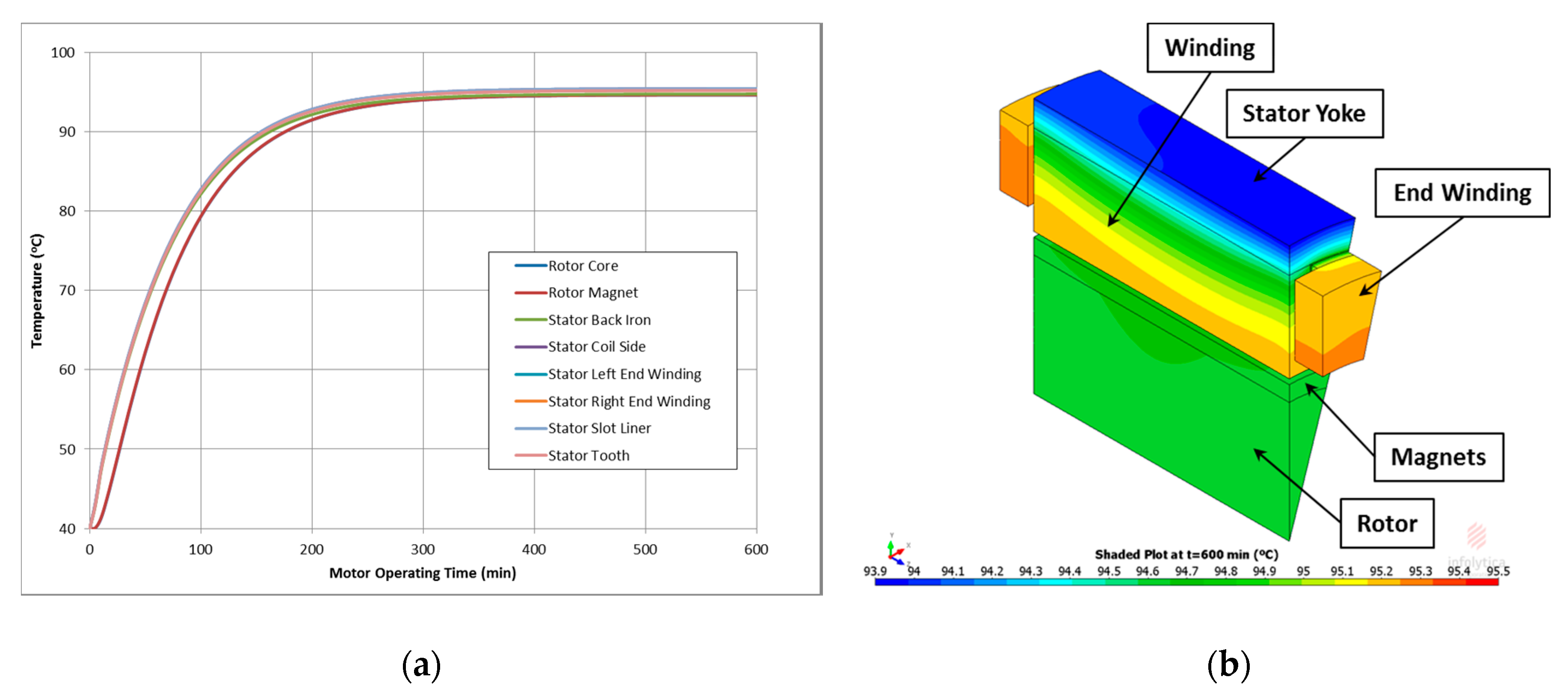
In the present study, Hiperco 50A alloy is used as the motor core material and the stator slot encapsulation material (CW 2710/HW 2711, Huntsman, Woodlands, TX, USA) is used for slot potting and thermal conduction enhancement. Further studies regarding different motor materials can be performed. The temperature distribution of the present SPM motor (10p/12s) is modeled to examine whether overheat occurs with present conditions. Shown in Figure 16a is the time-based temperature variation for different motor components, under the operating conditions mentioned in Table 1; Figure 16b shows the axisymmetric temperature distribution in the 3-D motor model, provided by MotorSolve FEA simulation. The ambient temperature for this case study is set to be 40 °C. All three heat transfer mechanisms, conduction (within the motor solid assembly), convection (on motor external surface) and radiation (on motor external surface) are considered. In this case shown in Figure 16, no overheat is observed under the present operating condition. Taking into account the end winding heat effect, the maximum temperature would occur within the copper windings and their ends, where the copper heat loss is generated and has the longest distance (length of thermal transfer path) to the low-temperature ambient.
Although the configuration of Halbach Array magnet and its advantages are reported previously, the torque dense capability of a Halbach Array motor is not widely realized. In the present study, Halbach Array SPM motors are verified to be able to produce higher torque than a conventional SPM with the same magnet volume and at the same rotor speed, provided the optimal Halbach Array magnet ratio, Rmp, is applied. It is also noted that compared to induction motor (IM) machines, the permanent magnet (PM) motors, including SPM and IPM (interior permanent magnet) machines, are able to achieve greater torque/current density, also with higher efficiency and reliability in low speed operation [35].
On the other hand, the general torque production also implies that in these motor categories, lower supply current may be required to retain the same torque performance using the Halbach Array SPM motor compared to others including the standard IM motors. As a result, lower supply current will present lower copper heat loss. Therefore, for industrial applications such as subsea electrical submersible pumps (ESP) or progressive cavity pumps (PCP), which require of driving motors with high torque density at a relative lower speed [36], the Halbach Array SPM motor is a good choice for its ability of high torque dense performance, with lower heat loss and higher efficiency. Such high-torque, low-speed motors could also eliminate the necessity of using a gear-reduction unit to reduce the high rotational speed driven by an IM machine, and reduce its mechanical loss and possible failures.

5. Conclusions

Developed in this paper is a subdomain model accounting for tooth-tip and slot effects for surface mounted permanent magnet (SPM) Halbach Array motor. The proposed analytical model can accurately predict the electromagnetic flux field distributions in motor applications of conventional and Halbach Array SPM machines. Based on the resultant magnetic field, the electromagnetic performances of the motor, such as the cogging torque, back-EMF, and electromagnetic torque are accurately calculated. The FEA analysis validates the predictions of the proposed analytical model. At this stage, a 2-D model is developed. For future work, there are certain difficulties to perform simulations in 3-D basis; hence an experimental setup is needed to validate the model.
Due to the feature of Halbach Array magnet configuration, the magnetic flux field is augmented on one side (outward of rotor), while cancelled on the other side (inward of rotor). In the present study, much less flux saturation is observed in rotor back iron with Halbach Array configuration compared to the conventional ones. Thus in Halbach Array design, more magnets could be installed in the rotor to achieve higher torque, with lower risk to cause flux saturation within the rotor back iron; on the other hand, less back iron material is needed in the Halbach Array designed rotor.
Also, we conclude that the Halbach Array magnet ratio would be one of the most important design parameters in Halbach Array SPM motors, because it influences on the flux density in both peak value and waveform which will therefore stimulate the resultant torque. With the appropriate magnet ratio in the motor embodiment, the Halbach Array motor is capable to produce higher torque than the conventional SPM motor for the same volume of magnets. Furthermore, potentially lower supply current requirement of the Halbach Array SPM motor would reduce the heat loss and increase the motor operating efficiency. For the industry applications (such as PCP motor) with direct-drive motors operating at low rotor-speed, it suggests that with magnet ratio optimization, the Halbach Array SPM motor is capable to exceed other machines (IM, IPM, or conventional SPM) in both torque performance and efficiency. In the low speed operation, the Halbach Array SPM motor could be able to provide 10-25% more overall torque, with the same motor size and the same input current.

Author Contributions

Methodology, M.M. and J.L.; software, Y.T. and T.W.; validation, M.M., Y.T.; thermal analysis, Y.T.; resources, M.A.F. and J.P.; writing-original draft preparation, M.M., Y.T. and T.W.; writing—review and editing, M.A.F. and J.P.; supervision, M.A.F. and J.P.

Funding

This research received no external funding.

Conflicts of Interest

The authors declare no conflict of interest.

References

  1. Zhu, Z.Q.; Howe, D. Halbach permanent magnet machines and applications: A review. IEE Proc. Electr. Power Appl. 2001, 148, 299–308. [Google Scholar] [CrossRef]
  2. Ng, K.; Zhu, Z.; Howe, D. Open-circuit field distribution in a brushless motor with diametrically magnetised PM rotor, accounting for slotting and eddy current effects. IEEE Trans. Magn. 1996, 32, 5070–5072. [Google Scholar] [CrossRef]
  3. Shen, Y.; Liu, G.Y.; Xia, Z.P.; Zhu, Z.Q. Determination of maximum electromagnetic torque in PM brushless machines having two-segment Halbach array. IEEE Trans. Ind. Electr. 2014, 61, 718–729. [Google Scholar] [CrossRef]
  4. Wang, H.; Ye, Y.; Wang, Q.; Dai, Y.; Yu, Y.; Weng, P. Analysis for ring arranged axial field Halbach permanent magnets. IEEE Trans. Appl. Supercond. 2006, 16, 1562–1565. [Google Scholar] [CrossRef]
  5. Looser, A.; Baumgartner, T.; Kolar, J.W.; Zwyssig, C. Analysis and measurement of three-dimensional torque and forces for slotless permanent-magnet motors. IEEE Trans. Ind. Appl. 2012, 48, 1258–1266. [Google Scholar] [CrossRef]
  6. Jang, S.-M.; Jeong, S.-S.; Ryu, D.-W.; Choi, S.-K. Design and analysis of high speed slotless PM machine with Halbach array. IEEE Trans. Magn. 2001, 37, 2827–2830. [Google Scholar] [CrossRef]
  7. Wu, L.; Zhu, Z.Q.; Staton, D.; Popescu, M.; Hawkins, D. An improved subdomain model for predicting magnetic field of surface-mounted permanent magnet machines accounting for tooth-tips. IEEE Trans. Magn. 2011, 47, 1693–1704. [Google Scholar] [CrossRef]
  8. Zhu, Z. Recent development of Halbach permanent magnet machines and applications. In Proceedings of the Power Conversion Conference-Nagoya, Nagoya, Japan, 2–5 April 2007. [Google Scholar]
  9. Zhu, Z.; Xia, Z.; Howe, D. Comparison of Halbach magnetized brushless machines based on discrete magnet segments or a single ring magnet. IEEE Trans. Magn. 2002, 38, 2997–2999. [Google Scholar] [CrossRef] [Green Version]
  10. Dwari, S.; Parsa, L. Design of halbach-array-based permanent-magnet motors with high acceleration. IEEE Trans. Ind. Electron. 2011, 58, 3768–3775. [Google Scholar] [CrossRef]
  11. Wang, J.; Howe, D.; Lin, Z. Design optimization of short-stroke single-phase tubular permanent-magnet motor for refrigeration applications. IEEE Trans. Ind. Electron. 2010, 57, 327–334. [Google Scholar] [CrossRef]
  12. Halbach, K. Design of permanent multipole magnets with oriented rare earth cobalt material. Nuclear Instrum. Methods 1980, 169, 1–10. [Google Scholar] [CrossRef]
  13. Dhulipati, H.; Mukundan, S.; Lakshmi Varaha Iyer, K.; Kar, N.C. Skewing of stator windings for reduction of spatial harmonics in concentrated wound PMSM. In Proceedings of the 2017 IEEE 30th Canadian Conference on Electrical and Computer Engineering (CCECE), Windsor, ON, Canada, 30 April–3 May 2017. [Google Scholar]
  14. Hwang, C.; Cheng, S.; Li, P. Design optimization for cogging torque minimization and efficiency maximization of an SPM motor. In Proceedings of the 2007 IEEE International Electric Machines & Drives Conference, Antalya, Turkey, 3–5 May 2007. [Google Scholar]
  15. Islam, J.; Svechkarenko, D.; Chin, R.; Szucs, A.; Mantere, J.; Sakki, R. Cogging torque and vibration analysis of a direct-driven PM wind generator with concentrated and distributed windings. In Proceedings of the 2012 15th International Conference on Electrical Machines and Systems (ICEMS), Sapporo, Japan, 21–24 October 2012. [Google Scholar]
  16. Lee, J.; Nomura, T.; Dede, E.M. Topology optimization of Halbach magnet arrays using isoparametric projection. J. Magn. Magn. Mate. 2017, 432, 140–153. [Google Scholar] [CrossRef]
  17. Braune, S.; Liu, S.; Mercorelli, P. Design and control of an electromagnetic valve actuator. In Proceedings of the 2006 IEEE Conference on Computer Aided Control System Design, 2006 IEEE International Conference on Control Applications and 2006 IEEE International Symposium on Intelligent Control, Munich, Germany, 4–6 October 2006. [Google Scholar]
  18. Mercorelli, P.; Lehmann, K.; Liu, S. Robust flatness based control of an electromagnetic linear actuator using adaptive PID controller. In Proceedings of the 42nd IEEE International Conference on Decision and Control, Maui, HI, USA, 9–12 December 2003. [Google Scholar]
  19. Furlani, E.P. Permanent Magnet and Electromechanical Devices: Materials, Dnalysis, and Applications, 1st ed.; Academic Press: New York, NY, USA, 2001; ISBN 978-0-12-269951-1. [Google Scholar]
  20. Liu, G.; Shao, M.; Zhao, W.; Ji, J.; Chen, Q.; Feng, Q. Modeling and analysis of halbach magnetized permanent-magnets machine by using lumped parameter magnetic circuit method. Prog. Electromagn. Res. M 2015, 41, 177–188. [Google Scholar] [CrossRef]
  21. Jin, P.; Yuan, Y.; Lin, H.; Fang, S.; Ho, S.L. General analytical method for magnetic field analysis of Halbach magnet arrays based on magnetic scalar potential. J. Magn. 2013, 18, 95–104. [Google Scholar] [CrossRef]
  22. Jang, S.-M.; Choi, J.-Y. Analytical prediction for electromagnetic characteristics of tubular linear actuator with Halbach array using transfer relations. J. Electr. Eng. Technol. 2007, 2, 221–230. [Google Scholar] [CrossRef]
  23. Wu, L.J.; Zhu, Z.Q.; Staton, D.; Popescu, M.; Hawkins, D. Analytical prediction of electromagnetic performance of surface-mounted PM machines based on subdomain model accounting for tooth-tips. IET Electr. Power Appl. 2011, 5, 597–609. [Google Scholar] [CrossRef]
  24. Wu, L.J.; Zhu, Z.Q.; Staton, D.; Popescu, M.; Hawkins, D. Subdomain model for predicting armature reaction field of surface-mounted permanent-magnet machines accounting for tooth-tips. IEEE Trans. Magn. 2011, 47, 812–822. [Google Scholar] [CrossRef]
  25. Markovic, M.; Perriard, Y. Optimization design of a segmented Halbach permanent-magnet motor using an analytical model. IEEE Trans. Magn. 2009, 45, 2955–2960. [Google Scholar] [CrossRef]
  26. Mellor, P.H.; Wrobel, R. Optimization of a multipolar permanent-magnet rotor comprising two arc segments per pole. IEEE Trans. Ind. Appl. 2007, 43, 942–951. [Google Scholar] [CrossRef]
  27. Kumar, P.; Bauer, P. Improved analytical model of a permanent-magnet brushless DC motor. IEEE Trans. Magn. 2008, 44, 2299–2309. [Google Scholar] [CrossRef]
  28. Boughrara, K.; Zarko, D.; Ibtiouen, R.; Touhami, O.; Rezzoug, A. Magnetic field analysis of inset and surface-mounted permanent-magnet synchronous motors using Schwarz–Christoffel transformation. IEEE Trans. Magn. 2009, 45, 3166–3178. [Google Scholar] [CrossRef]
  29. Wu, L.; Zhu, Z.Q.; Staton, D.; Popescu, M.; Hawkins, D. Combined complex permeance and sub-domain model for analytical predicting electromagnetic performance of surface-mounted PM machines. In Proceedings of the 5th IET International Conference on Power Electronics, Machines and Drives, Brighton, UK, 19–21 April 2010. [Google Scholar]
  30. Zhu, Z.; Howe, D. Analytical prediction of the cogging torque in radial-field permanent magnet brushless motors. IEEE Trans. Magn. 1992, 28, 1371–1374. [Google Scholar] [CrossRef]
  31. Zarko, D.; Ban, D.; Lipo, T.A. Analytical calculation of magnetic field distribution in the slotted air gap of a surface permanent-magnet motor using complex relative air-gap permeance. IEEE Trans. Magn. 2006, 42, 1828–1837. [Google Scholar] [CrossRef]
  32. Zarko, D.; Ban, D.; Lipo, T.A. Analytical solution for cogging torque in surface permanent-magnet motors using conformal mapping. IEEE Trans. Magn. 2008, 44, 52–65. [Google Scholar] [CrossRef]
  33. Zhu, L.; Jiang, S.Z.; Zhu, Z.Q.; Chan, C.C. Analytical methods for minimizing cogging torque in permanent-magnet machines. IEEE Trans. Magn. 2009, 45, 2023–2031. [Google Scholar] [CrossRef]
  34. De La Ree, J.; Boules, N. Torque production in permanent-magnet synchronous motors. IEEE Trans. Ind. Appl. 1989, 25, 107–112. [Google Scholar] [CrossRef]
  35. Pellegrino, G.; Vagati, A.; Boazzo, B.; Guglielmi, P. Comparison of induction and PM synchronous motor drives for EV application including design examples. IEEE Trans. Ind. Appl. 2012, 48, 2322–2332. [Google Scholar] [CrossRef]
  36. Cui, J.; Zhang, X.J.; Zhang, X.; Zhang, P. Electric Submersible Progressing Cavity Pump Driven by Low-Speed Permanent Magnet Synchronous Motor. In Proceedings of the SPE Middle East Artificial Lift Conference and Exhibition, Manama, Kingdom of Bahrain, 30 November–1 December 2016. [Google Scholar]
Figure 1. Symbols and Regions of Subdomain Model with Tooth-tips.
Energies 11 03254 g001
Figure 2. Radial Component of Magnetization for Two Magnet Ratios (0.5 and 0.75).
Energies 11 03254 g002
Figure 3. Circumferential Component of Magnetization for Two Magnet Ratios (0.5 and 0.75).
Energies 11 03254 g003
Figure 4. Halbach Array Magnet Ring.
Energies 11 03254 g004
Figure 5. Non-Overlapping Winding Layout in MotorSolve.
Energies 11 03254 g005
Figure 6. Comparison of FEA and Analytically Predicted Air-gap Flux Density, Rmp = 0.5.
Energies 11 03254 g006
Figure 7. Comparison of Analytically Predicted Air-gap Flux Density with Different Magnet Ratio Values.
Energies 11 03254 g007
Figure 8. Analytical and MotorSolve FEA Predictions of Electromagnetic in the 12 s/10 p Halbach Machine with Rmp = 0.5 (average deviation: 1.8%).
Energies 11 03254 g008
Figure 9. Analytical and MotorSolve Predictions of Cogging Torque in the 12 s/10 p Halbach Machine with Rmp = 0.5.
Energies 11 03254 g009
Figure 10. Analytical and MotorSolve Predictions of Back EMF in the 12 s/10 p Halbach Machine with Rmp = 0.5.
Energies 11 03254 g010
Figure 11. Magnetic Field Distributions across the Motor Area: (a) Rmp = 0.5; (b) Rmp = 0.7; (c) Rmp = 1.
Energies 11 03254 g011
Figure 12. Analytical and MotorSolve FEA Predictions of Electromagnetic in the 12 s/10 p Conventional Machine (average deviation: 1.6%).
Energies 11 03254 g012
Figure 13. Analytical and MotorSolve Predictions of Cogging Torque in the 12 s/10 p Conventional Machine.
Energies 11 03254 g013
Figure 14. Analytical and MotorSolve Predictions of Back EMF in the 12 s/10 p Conventional Machine.
Energies 11 03254 g014
Figure 15. Comparison of Analytically Predicted Torque with Different Magnet Ratio Values.
Energies 11 03254 g015
Figure 16. Motor Thermal Analysis Results: (a) Time-based Temperature Profiles for Various Motor Components; (b) Temperature Contours for 3D Thermal Modeling at 600 min.
Energies 11 03254 g016
Table 1. Main Motor Parameters.
ParameterValue
Slot Number, Ns12
Pole Number, p10
Stator Outer Diameter, Ds100 mm
Magnet Remanence, Br1.12 T
Relative Permeability, μ1.05
Air gap Length, g1 mm
Magnet Thickness, hm3 mm
Active Length, L50 mm
Winding Turns / Coil, Nc35
Magnet MagnetizationRadial
Stator Inner Diameter55 mm
Tooth Tips Edge3 mm
Slot-opening Angle5.5°
Winding Slot Angle14.5°
Stator Yoke Height5 mm
Rotor Outer Diameter53 mm
Peak Rated Current10 A
Motor Speed400 RPM

