Microbial Fuel Cell with Ni–Co Cathode Powered with Yeast Wastewater


Abstract
1. Introduction
2. Materials and Methods
3. Results
4. Discussion
5. Conclusions
Author Contributions
Funding
Acknowledgments
Conflicts of Interest
Nomenclature
| AF | agricultural fields |
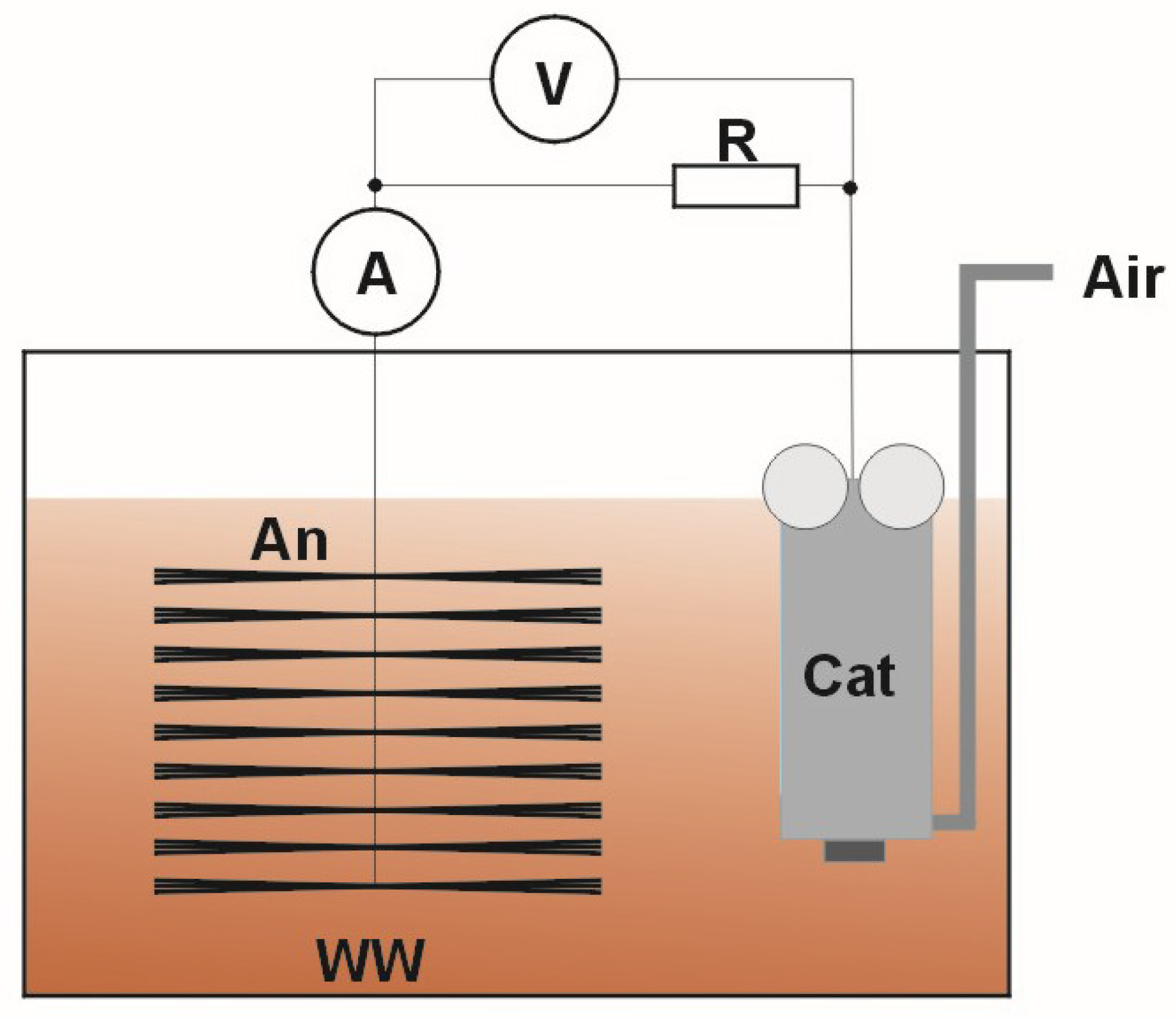
| An | anode |
| Cat | cathode |
| COD | chemical oxygen demand |
| DWW | domestic wastewater |
| HIPS | high impact polystyrene |
| IWW | industrial wastewater |
| MFC | microbial fuel cell |
| PEM | proton exchange membrane |
| PWW | process wastewater |
| WW | wastewater |
| WWTP | wastewater treatment plant |
References
- Gallouj, F.; Weber, K.M.; Stare, M.; Rubalcaba, L. The futures of the service economy in Europe: A foresight analysis. Tech. Forecast. Soc. Chang. 2015, 94, 80–96. [Google Scholar] [CrossRef]
- Menrad, K. Market and marketing of functional food in Europe. J. Food Eng. 2003, 56, 181–188. [Google Scholar] [CrossRef]
- Arvanitoyannis, I.S. Waste Management for the Food Industry; Elsevier: Amsterdam, The Netherlands, 2010. [Google Scholar]
- Cecconet, D.; Molognoni, D.; Callegari, A.; Capodaglio, A.G. Agro-food industry wastewater treatment with microbial fuel cells: Energetic recovery issues. Int. J. Hydrog. Energy 2018, 43, 500–511. [Google Scholar] [CrossRef]
- Barbera, M.; Gurnari, G. Wastewater Treatment and Reuse in the Food Industry; Springer: Cham, Switzerland, 2018. [Google Scholar]
- Logan, B. Microbial Fuel Cells; Wiley: Hoboken, NJ, USA, 2008. [Google Scholar]
- Ravindran, R.; Jaiswal, A.K. Exploitation of food industry waste for high-value products. Trends Biotechnol. 2016, 34, 58–69. [Google Scholar] [CrossRef] [PubMed]
- Cusick, R.D.; Kim, Y.; Logan, B.E. Energy capture from thermolytic solutions in microbial reverse-electrodialysis cells. Science 2012, 335, 1474–1477. [Google Scholar] [CrossRef] [PubMed]
- Utilization of By-Products and Treatment of Waste in the Food Industry; Oreopoulou, V., Russ, W., Eds.; Springer: New York, NY, USA, 2007. [Google Scholar]
- Russ, W.; Meyer-Pittroff, R. Utilizing waste products from the food production and processing industries. Critical Rev. Food Sci. Nutr. 2010, 44, 57–62. [Google Scholar] [CrossRef] [PubMed]
- Muszyńska, B.; Mirosław Malec, M.; Sułkowska-Ziaja, K. Medicinal and cosmetological properties of Saccharomyces Cerevisiae. Postępy Fitoterapii 2013, 1, 54–62. [Google Scholar]
- Paruch, A.M.; Pulikowski, K.; Bawiec, A.; Pawęska, K. Assessment of Groundwater Quality in Areas Irrigated with Food Industry Wastewater: A Case of Wastewater Utilisation from Sugar and Yeast Factories. Envir. Process. 2017, 4, 799–812. [Google Scholar] [CrossRef]
- Begea, M.; Berkesy, C.; Berkesy, L.; Cîrîc, A.; Bărbulescu, I.D. Study of the recovery in agriculture of the waste resulted from baker’s yeast industry. Adv. Agric. Botanics 2017, 9, 136–145. [Google Scholar]
- Davis, J.B.; Yarbrough, H.F., Jr. Preliminary experiments on a microbial fuel cell. Science 1962, 137, 615–616. [Google Scholar] [CrossRef] [PubMed]
- Franks, A.E.; Nevin, K.P. Microbial fuel cells, a current review. Energies 2010, 3, 899–919. [Google Scholar] [CrossRef]
- Min, B.; Logan, B.E. Continuous electricity generation from domestic wastewater and organic substrates in a at plate microbial fuel cell. Environ. Sci. Technol. 2004, 38, 5809–5814. [Google Scholar] [CrossRef] [PubMed]
- Min, B.; Cheng, S.; Logan, B.E. Electricity generation using membrane and salt bridge microbial fuel cells. Water Res. 2005, 39, 1675–1686. [Google Scholar] [CrossRef] [PubMed]
- Wang, X.; Feng, Y.J.; Lee, H. Electricity production from beer brewery wastewater using single chamber microbial fuel cell. Water Sci. Technol. 2008, 57, 1117–1121. [Google Scholar] [CrossRef] [PubMed]
- Rabaey, K.; Verstraete, W. Microbial fuel cells: Novel biotechnology for energy generation. Trend. Biotechnol. 2005, 23, 291–298. [Google Scholar] [CrossRef] [PubMed]
- Logan, B.E.; Hamelers, B.; Rozendal, R.; Schroder, U.; Keller, J.; Verstraete, W.; Rabaey, K. Microbial Fuel Cells: Methodology and Technology. Environ. Sci. Technol. 2006, 40, 5181–5192. [Google Scholar] [CrossRef] [PubMed]
- Bond, D.R.; Lovley, D.R. Electricity production by Geobacter sulfurreducens attached to electrodes. Appl. Envir. Microbiol. 2003, 69, 1548–1555. [Google Scholar] [CrossRef]
- Chaudhuri, S.K.; Lovley, D.R. Electricity generation by direct oxidation of glucose in mediatorless microbial fuel cells. Nat. Biotechnol. 2003, 21, 1229–1232. [Google Scholar] [CrossRef] [PubMed]
- Kim, H.J.; Park, H.S.; Hyun, M.S.; Chang, I.S.; Kim, M.; Kim, B.H. A Mediator-Less Microbial Fuel Cell Using a Metal Reducing Bacterium, Shewanella Putrefaciens. Enzym. Microb. Technol. 2002, 30, 145–152. [Google Scholar] [CrossRef]
- Park, H.S.; Kim, B.H.; Kim, H.S.; Kim, H.J.; Kim, G.T.; Kim, M.; Chang, I.S.; Park, Y.K.; Chang, H.I. A novel electrochemically active and Fe(III)-reducing bacterium phylogenetically related to Clostridium butyricum isolated from a microbial fuel cell. Anaerobe 2001, 7, 297–306. [Google Scholar] [CrossRef]
- Pham, C.A.; Jung, S.J.; Phung, N.T.; Lee, J.; Chang, I.S.; Kim, B.H.; Yi, H.; Chun, J. A novel electrochemically active and Fe(III)-reducing bacterium phylogenetically related to Aeromonas hydrophila, isolated from a microbial fuel cell. FEMS Microbiol. Lett. 2003, 223, 129–134. [Google Scholar] [CrossRef]
- Bond, D.R.; Lovley, D.R. Evidence for involvement of an electron shuttle in electricity generation by Geothrix fermentans. Appl. Environ. Microbiol. 2005, 71, 2186–2189. [Google Scholar] [CrossRef] [PubMed]
- Reguera, G.; McCarthy, K.D.; Mehta, T.; Nicoll, J.S.; Tuominen, M.T.; Lovley, D.R. Extracellular electron transfer via microbial nanowires. Nature 2005, 435, 1098–1101. [Google Scholar] [CrossRef] [PubMed]
- Reguera, G.; Nevin, K.P.; Nicoll, J.S.; Covalla, S.F.; Woodard, T.L.; Lovley, D.R. Biofilm and nanowire production leads to incre- ased current in Geobacter sulfurreducens fuel cells. Appl. Environ. Microbiol. 2006, 72, 7345–7348. [Google Scholar] [CrossRef] [PubMed]
- Patil, S.A.; Surakasi, V.P.; Koul, S.; Ijmulwar, S.; Vivek, A.; Shouche, Y.S.; Kapadnis, B.P. Electricity generation using chocolate industry wastewater and its treatment in activated sludge based microbial fuel cell and analysis of developed microbial community in the anode chamber. Bioresour. Technol. 2009, 100, 5132–5139. [Google Scholar] [CrossRef] [PubMed]
- Zhang, X.; Cheng, S.; Huang, X.; Logan, B.E. Improved performance of single-chamber microbial fuel cells through control of membrane deformation. Biosens. Bioelectron. 2010, 25, 1825–1828. [Google Scholar] [CrossRef] [PubMed]
- Aelterman, P.; Freguia, S.; Keller, J.; Verstraete, W.; Rabaey, K. The anode potential regulates bacterial activity in microbial fuel cells. Appl. Microbiol. Biotechnol. 2008, 78, 409–418. [Google Scholar] [CrossRef] [PubMed]
- Juang, D.F.; Lee, C.H.; Hsueh, S.C.; Chou, H.Y. Power generation capabilities of microbial fuel cells with di erent oxygen supplies in the cathodic chamber. Appl. Biochem. Biotechnol. 2012, 167, 714–731. [Google Scholar] [CrossRef] [PubMed]
- Angenent, L.T.; Karima, K.; Al-Dahhan, M.H.; Wrenn, B.A.; Domíguez-Espinosa, R. The wastewater from yeast factory was used in measurements. Production of bioenergy and biochemicals from industrial and agricultural wastewater. Trend. Biotechnol. 2004, 22, 477–485. [Google Scholar] [CrossRef] [PubMed]
- Verstraete, W.; Morgan-Sagastume, F.; Aiyuk, S.; Rabaey, K.; Waweru, M.; Lissens, G. Anaerobic digestion as a core technology in sustainable management of organic matter. Water Sci. Technol. 2005, 52, 59–66. [Google Scholar] [CrossRef] [PubMed]
- Tsai, H.Y.; Wu, C.C.; Lee, C.Y.; Shih, E.P. Microbial fuel cell performance of multiwall carbon nanotubes on carbon cloth as electrodes. J. Power Source 2009, 194, 199–205. [Google Scholar] [CrossRef]
- Dumas, C.; Mollica, A.; Féron, D.; Basséguy, R.; Etcheverry, L.; Bergel, A. Marine microbial fuel cell: Use of stainless steel electrodes as anode and cathode materials. Electrochim. Acta 2006, 53, 468–473. [Google Scholar] [CrossRef]
- Martin, E.; Tartakovsky, B.; Savadogo, O. Cathode materials evaluation in microbial fuel cells: A comparison of carbon, Mn2O3, Fe2O3 and platinum materials. Electrochim. Acta 2011, 58, 58–66. [Google Scholar] [CrossRef]
- Włodarczyk, B.; Włodarczyk, P.P. Microbial fuel cell with Cu-B cathode powering with wastewater from yeast production. J. Ecol. Eng. 2017, 18, 224–230. [Google Scholar] [CrossRef]
- Włodarczyk, B.; Włodarczyk, P.P. Use of Ni-Co alloy as cathode catalyst in single chamber microbial fuel cell. Ecol. Eng. 2017, 18, 210–216. [Google Scholar] [CrossRef]
- Włodarczyk, P.P.; Włodarczyk, B. Possibility of Using Ni-Co Alloy as Catalyst for Oxygen Electrode of Fuel Cell. Chin. Bus. Rev. 2015, 14, 159–167. [Google Scholar] [CrossRef]
- Włodarczyk, P.P.; Włodarczyk, B. Ni-Co alloy as catalyst for fuel electrode of hydrazine fuel cell. China-USA Bus. Rev. 2015, 14, 269–279. [Google Scholar] [CrossRef]
- Huggins, T.; Fallgren, P.H.; Jin, S.; Ren, Z.J. Energy and performance comparison of microbial fuel cell and conventional aeration treating of wastewater. J. Microb. Biochem. Technol. 2013, S6-002. [Google Scholar] [CrossRef]
- Włodarczyk, B.; Włodarczyk, P.P.; Kalinichenko, A. Single chamber microbial fuel cell with Ni-Co cathode. In Proceedings of the International Conference Energy, Environment and Material Systems (EEMS 2017), Polanica Zdrój, Poland, 13–15 September 2017. [Google Scholar]


| Parameter | Value |
|---|---|
| COD [mg⋅L−1] | 3266 |
| pH | 6.5 ± 0.1 |
| Component | Volume [g⋅L−1] | pH | Temperature [K] | Current Density [A⋅dm−2] | Co Concentration [%] |
|---|---|---|---|---|---|
| NiSO4·7H2O CoSO4·7H2O H3BO3 | 260 14 15 | 3.0 | 293 | 1.6 | 15 |
| NiSO4·7H2O CoSO4·7H2O H3BO3 NaCl | 200 20 30 15 | 5.5 | 293 | 1.0 | 25 |
| NiSO4·7H2O CoSO4·7H2O | 195 35 | 2.0 | 293 | 3.0 | 50 |
| NiSO4·7H2O CoSO4·7H2O H3BO3 NaCl | 140 120 30 15 | 4.0 | 323 | 1.0 | 75 |
© 2018 by the authors. Licensee MDPI, Basel, Switzerland. This article is an open access article distributed under the terms and conditions of the Creative Commons Attribution (CC BY) license (http://creativecommons.org/licenses/by/4.0/).
Share and Cite
Włodarczyk, P.P.; Włodarczyk, B. Microbial Fuel Cell with Ni–Co Cathode Powered with Yeast Wastewater. Energies 2018, 11, 3194. https://doi.org/10.3390/en11113194
Włodarczyk PP, Włodarczyk B. Microbial Fuel Cell with Ni–Co Cathode Powered with Yeast Wastewater. Energies. 2018; 11(11):3194. https://doi.org/10.3390/en11113194
Chicago/Turabian StyleWłodarczyk, Paweł P., and Barbara Włodarczyk. 2018. "Microbial Fuel Cell with Ni–Co Cathode Powered with Yeast Wastewater" Energies 11, no. 11: 3194. https://doi.org/10.3390/en11113194
APA StyleWłodarczyk, P. P., & Włodarczyk, B. (2018). Microbial Fuel Cell with Ni–Co Cathode Powered with Yeast Wastewater. Energies, 11(11), 3194. https://doi.org/10.3390/en11113194