1. Introduction
The electricity demand is forecasted to increase significantly in the near future. In order to meet this projected demand, the rapid deployment of cost-effective and environment-friendly Renewable Energy Sources is evident in different parts of the world. This change, from conventional to Renewable Energy Sources (RES) for electricity generation, has further led to the development of small-scale power generating units called Microgrids with the aim of shifting partially certain loads from interconnected power system to a new concept of the distributed generation system.
A Microgrid (MG) is basically a cluster of loads supplied by micro-sources such as wind turbines, micro-turbines, solar Photovoltaic (PV) and fuel cells operating as a sole controllable system which is capable of delivering both heat and power to the specified area [
1,
2]. The interconnection of MGs can be controlled and adjusted to enable them to work in both grid-connected and islanded modes of operation respectively [
3]. In the grid-connected mode, the MG deliver power to the utility grid during peak load hours of the day, or alternatively, it may import the power from the grid to meet the specified load connected to MG. During this mode of operation, the major control concern is to regulate the active and reactive power flow among Distributed Generators (DG) connected within the MG and between MG and the main grid. Furthermore, for the grid-connected mode of MG operation with the main grid, the system’s voltage and frequency are controlled by the giant power system, and hence it is not a control objective for MG controls. However, in the islanding mode, besides maintaining the power balance, controlling the voltage and frequency of the MG system is also very crucial [
4]. This is so because the MG systems with high penetrations of DGs may experience severe voltage and frequency oscillations during DG insertion or load change. Moreover, the MG control system must also ensure that there are no large circulating reactive currents from the micro sources. A small error in voltage and frequency set points could cause the circulating currents which may exceed the ratings of the micro-sources [
5].
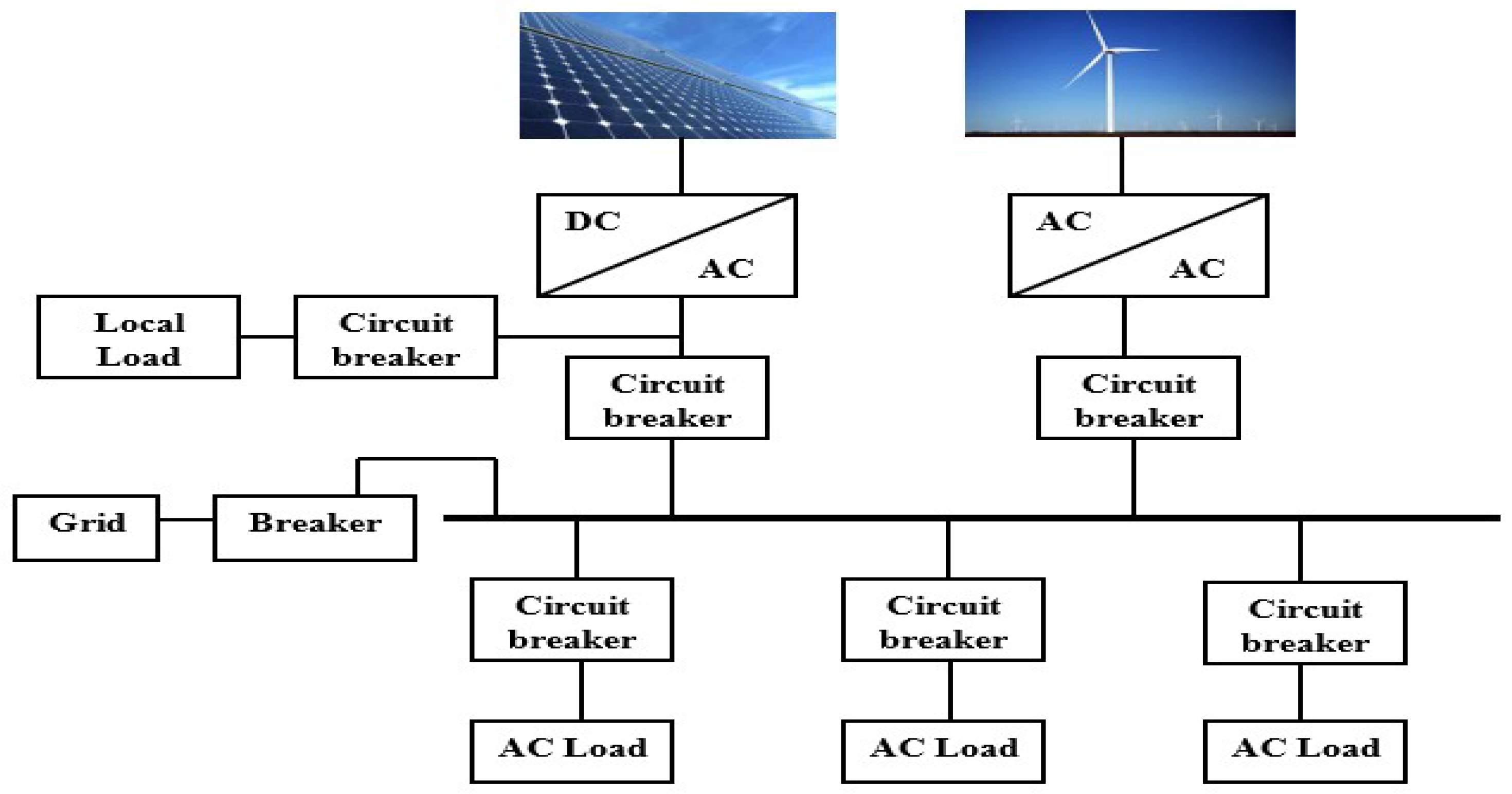
Figure 1 shows a general configuration of MG where it comprises two DGs; each one is connected to the Point of Common Coupling (PCC) through a power electronic interface. This interfacing is generally carried out using a non-linear power electronic device such as a Pulse Width Modulation (PWM) based Voltage Source Inverter (VSI) or the converter which is used to interconnect DGs within MG or with the utility grid [
6]. The major problem associated with these devices is that they produce a non-linearity between voltage and current due to the generation of high switching frequency pulses which distorts the power quality [
7], and hence MG faces severe challenges pertaining to the power quality, specifically when integrating an excessive number of DGs [
8,
9].
In order to satisfy the power quality standards and to ensure the smooth operation of the MG system, a robust control strategy is essentially required for both the grid-connected and islanded modes of its operation. It is pertinent to mention that lack of inertia and uncertainty in the selection of optimal Proportional Integral (PI) controller gains causes large variations in power, voltage, and the frequency level in the islanded mode as compared to the grid-connected mode of MG operation. Hence, this study is undertaken to address these concerns and enhance the performance of MG in the islanded mode of operation.
The study proposes a Grasshopper Optimization Algorithm (GOA) based controller to optimize the PI controller parameters to obtain the optimum dynamic response of an islanded MG. The GOA is one of the latest optimization algorithms introduced in the reference [
10] and is a more evolved algorithm than Genetic Algorithm (GA) and Particle Swarm Optimization (PSO) for solving the optimization problems [
10]. GOA has been applied and compared with conventional methods in solving many engineering problems like optimal distribution system reconfiguration and distributed generation placement [
11], optimal allocation of compensators [
12], and for load forecasting [
13]. This study employs GOA for solving the problem of determining the optimal PI parameters for regulating voltage and frequency of an islanded MG under the DG insertion and load change conditions. In addition, the droop control is incorporated in the control architecture as a power-sharing controller along with the voltage and current control loops. In order to validate the effectiveness of the proposed method, the performance of the GOA based Voltage-Frequency (v-f) controller is compared with that of the PSO and Whales Optimization Algorithm (WOA) based controllers for the same operating conditions.
Section 2 of this paper explains the related research work carried out in the mentioned area of research.
Section 3 provides the mathematical modeling of a three-phase grid-connected VSI model along with its control architecture. In
Section 4, the optimization and Fitness Function (FF) formulation has been undertaken.
Section 5 provides the detailed elaboration of GOA. In
Section 6, the results and analysis of the simulation are provided which duly validate the objectives of this research work, and finally,
Section 7 summaries the conclusion of this study.
2. Related Work in Literature
In recent studies [
3,
14], the power quality control objectives in islanded MGs were fairly accomplished by using voltage and current control loops to maintain the rated voltage and frequency. The most widely used controller for these control loops in MG control architecture is the PI controller for its simple realization, implementation, and higher reliability [
15]. However, a key shortcoming of the PI controllers is their limited performance as they are purely dependent on the proper tuning of their proportional and integral gain coefficients (
Kp and
Ki) [
16]. These coefficients can be set as static throughout the process or may be made dynamic using soft computational techniques. When using static gains in the PI regulator used for a voltage control loop, these gains are calculated using the adaptive or “trial and error” methods [
17,
18,
19] or the alternatively Ziegler-Nichols (Z-N) method [
20,
21,
22]. The key weaknesses related to these techniques, however, include the time-consumed towards performing the control actions, as such, they may result in a delay while entering an unstable region of operation [
23]. Therefore, the proper tuning of PI gains is very crucial and challenging in order to ensure an enhanced power quality and improved system performance during DG insertion and load changes [
24].
Most recently, with the advancement in the field of Artificial Intelligence (AI), the dynamic response of the MG system has been optimized using AI techniques, especially metaheuristic algorithms. The implementation of these AI-based controllers in the MG system ensured smooth integration and disconnection of DGs in the existing power system, a better transient voltage and frequency response during load changes, enhanced power quality for the end user and improved transient stability of the MG power system. In addition, these intelligent search techniques offer a better solution than conventional mathematical approaches for solving an optimization problem [
25]. Several studies have explored different AI techniques such as Fuzzy Logic (FL) [
26], the Genetic Algorithm (GA) [
25,
27], and PSO [
3,
28] by averting lengthy and inefficient traditional PI tuning methods for MG voltage and frequency control. The optimal values of PI parameters selected by the AI-based optimization algorithms have resulted in a better dynamic response of studied islanded MG systems as compared to the traditional tuning methods. However; these AI algorithms (FL, GA, and PSO) also suffer from a few major drawbacks. For example, the GA alone provides local solution convergence instead of a global solution and has been known for the difficulty of running with sets of the dynamic data turns it into an outdated method of optimization in modern MG controls [
29]. On the other hand, PSO suffers from low convergence rate in the iterative process, trapping into local minimum in high-dimensional space [
30] and uncertainty in its parameter selection [
31]. It performs reasonably well in the early iterations but finds snags in attaining an optimal solution in a few benchmark functions [
32].
Authors in reference [
3] developed a PSO based controller for regulating voltage and frequency of an islanded MG. The developed controller managed to optimize the system’s dynamic response in terms of regulating voltage within specified limits (±5% of the rated value), however, the frequency response violated the limit (±1% of the rated value) before getting stabilized. Furthermore, the PSO based controller was designed for an islanded MG by authors in Reference [
33]. The controller was able to regulate the frequency well within the specified limits despite the large source and load variations. However, the voltage profile of the studied MG system was not considered in the mentioned research work. Furthermore, it took more than 60 iterations to reach the optimized value of the fitness function, hence, it suffers from the slow convergence rate. Recently, the controllers for an islanded MG were developed by authors in References [
25,
14] using hybrid Big-Bang Big-Crunch (BB-BC) and Pareto based BB-BC algorithms respectively. The developed control architectures have managed to keep the voltage and frequency well within the standard limits. However, after the DG insertion and load change, the frequency level was settled to a new value (59.7 Hz) after a decline of 0.5% from its rated value (60 Hz) in both case studies. Most recently in Reference [
34], the Whales Optimization Algorithm (WOA) was utilized for the regulation of voltage and frequency separately by using two different cost functions in an autonomous MG. In the referred study [
34], the voltage and current were converted from three-phase (
abc) axis to direct-quadrature (
d-q) axis reference frame before the control loops using Park’s transformation. As such, the frequency (or its integral Ɵ) is included inside the conversion. However, it may be noted that the control of voltage and frequency are tied to one another [
25]. It is, therefore, not practical to separately optimize these two inter-related parameters. In order to address this limitation, the control architecture in this research work is designed with more simplicity and clarity employing GOA for the effective control of desired parameters.
3. MG Modelling along with the Proposed Control Strategy
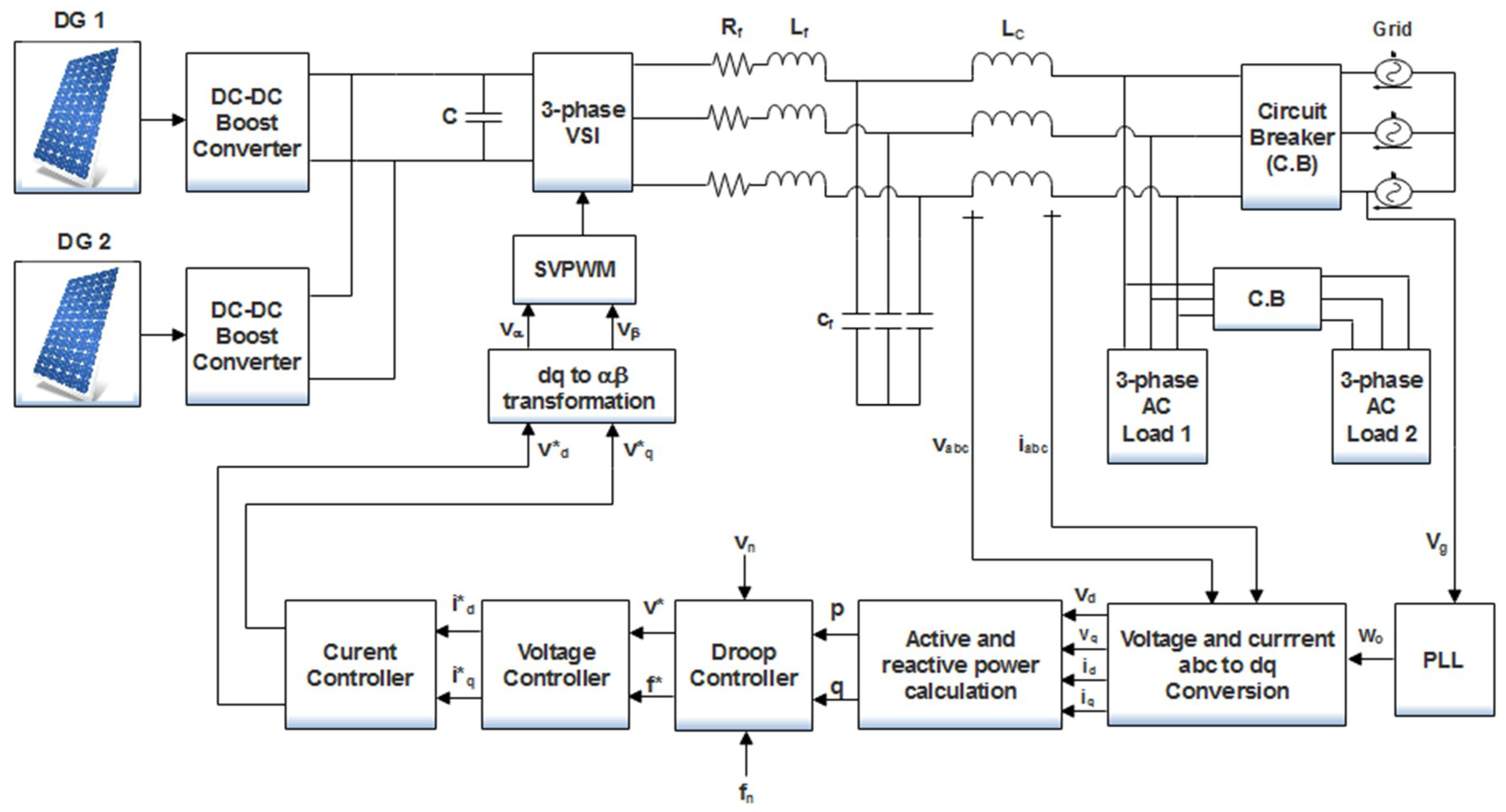
A detailed block diagram of the islanded MG system along with the proposed voltage and frequency control scheme is shown in
Figure 2. The power circuit comprises of two Solar PV panels, a DC-DC boost converter, three-phase VSI, a Resistive-Inductive-Capacitive (RLC) filter, a coupling inductor (L
c), and a three-phase load. To enhance the voltage profile and to extract the maximum power from the solar PV panels, a DC-DC boost converter is employed at the output terminals of the solar PV panels which incorporates the Maximum Power Point Tracking (MPPT) by employing the well-known Perturb and Observe (P & O) algorithm. The RLC filter is used to mitigate the harmonic and high-frequency contents and to maintain the pure sinusoidal voltage waveform across the load. A coupling inductor is placed in series with the RLC filter to minimize the coupling between the active and reactive power and operates as a harmonics damper. The grid is isolated from the MG and load through a three-phase circuit breaker. In order to make the output voltage in phase with the grid voltage (sinusoidal), the Phase Locked Loop (PLL) is used. The active and reactive powers provided by the DGs are calculated from the measured voltage and current values. Droop controller is used to generate the reference voltage and frequency signal for the voltage controller whose function is to generate the reference current signals for the current controller. Finally, the controlled pulses are generated for the 3-phase Voltage Source Inverter (VSI) using Space Vector Pulse Width Modulation (SVPWM) to supply the active and reactive power to the load at the rated voltage and frequency.
In
Figure 2 ,
and
,
refer to the output voltages and currents in the
d-q reference frame, respectively; C is dc side capacitance;
,
, and
are the per-phase resistance, capacitance, and inductance of the output filter, respectively;
and
refer to the three-phase MG voltage and current, respectively;
is the angular frequency of the grid output voltage;
stands for grid voltage; p and q represents the active and reactive power, respectively;
and
are the nominal voltage and frequency, respectively;
and
are the reference voltage and frequency values after the droop control, respectively;
,
and
,
are the reference currents and voltages in d and q axis, respectively;
and
are the equivalent voltage signals in the αβ reference frame.
The dynamics of the power circuit of the studied MG system has been modeled mathematically using Park’s transformation in state space equations as given in Equations (1) and (2) [
25];
where
,
and
,
represent the output voltages and currents after the filter, respectively.
3.1. Proposed Controller for Voltage and Frequency Control
In order to operate the MG in the islanding mode, the circuit breaker is kept open throughout the course of its operation. The function of the control circuit is to generate the controlled pulses for the VSI in order to produce a pure sinusoidal voltage waveform to transfer the generated power from the DG to load with high power quality. In order to enhance the dynamic response of the MG system, the proportional gain (
Kp) and integral gains (
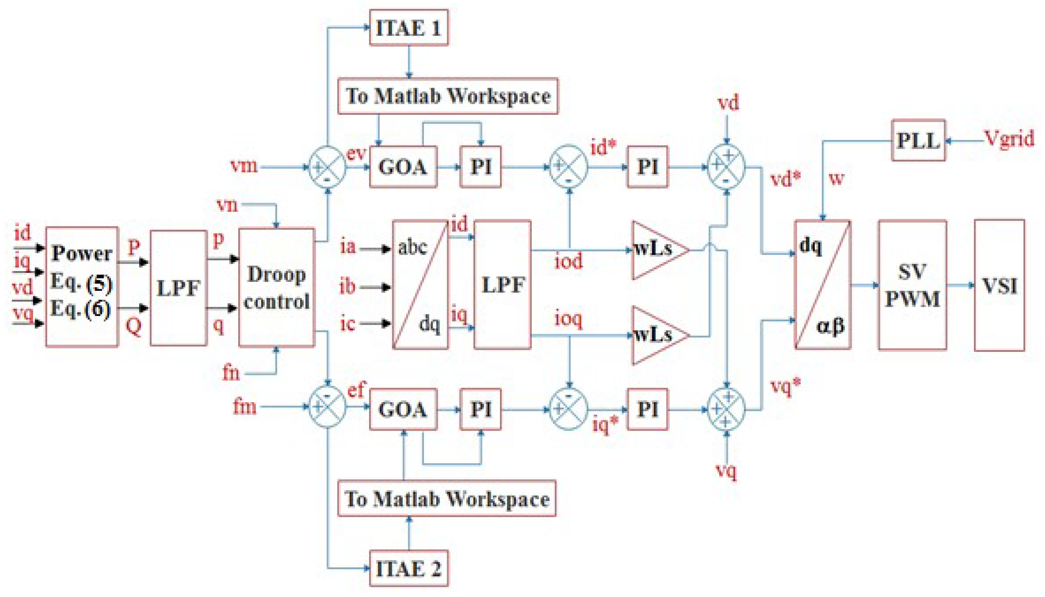
Ki) of the two PI controllers are optimized by using GOA. A detailed diagram of the proposed control strategy is shown in
Figure 3. Each part of the controller is described in detail in the subsequent sub-sections.
In
Figure 3, the
and
represent the measured voltage and frequency, respectively;
and
represent the voltage and frequency error respectively;
and
represent the nominal voltage and nominal frequency, respectively. LPF stands for the Low Pass Filter while ITAE stands for Integral Time Absolute Error.
Initially, the voltage and the current signals of the DG and the grid are measured and converted to the
d-q frame of reference using Park’s transformation by employing Equations (3) and (4);
where
,
,
and
are the per-phase voltages and currents, respectively. The active power (
P) and reactive power (
Q) supplied by DGs to the load in the
d-q reference frame is calculated by using Equations (5) and (6) respectively [
25].
A low pass filter is used in order to obtain the fundamental components of the active and reactive power and to reduce the impact of the current and power control loops on each other. The fundamental component of the active power (
p) and reactive power (
q) after the low pass filter are represented as given in Equations (7) and (8), respectively.
where
is the filter cut-off frequency and
is the Laplace transform operator.
3.2. Droop Control
The droop characteristics are used to generate the reference voltage and frequency for the islanded MG system based on the current load conditions in order to maintain its voltage and frequency profile. It may be noted that the reference values for the voltage and frequency can be kept constant (220 V, 50 Hz) without using droop control, as done so in Reference [
3]. However, the major disadvantage of this method is that the transient response of the system would be slower and hence takes a greater time to settle to steady state reference values after a load change or DG insertion in MG. As the load increases or decreases, a sharp decrement or increment in the voltage occurs due to an additional voltage drop in the load, filter impedance, and the coupling inductor. Similarly, the frequency of the voltage waveform may also be affected during the transition period due to the mismatch between the power generated and the power consumed. In the case of the conventional power system, the Automatic-Voltage Regulator and the turbine governor system are responsible for maintaining the voltage and frequency, respectively. However, these control schemes are not feasible for the solar PV system, and hence the droop can be effectively employed to maintain the voltage and frequency of the system during a sudden load change. The governing equations of the droop controller to find the reference angular frequency (
) and a reference voltage (
) are depicted in Equations (9) and (10) respectively;
where
represents the nominal angular frequency while
and
are the static droop coefficients for voltage and frequency, respectively. The values of the droop coefficients (
and
) can be calculated by using Equations (11) and (12);
where
and
are the maximum and minimum values of the angular frequency during load change,
and
are the maximum active and reactive power values connected to system and
and
are the maximum and minimum value of the voltage in
d-axis, respectively. It is evident from
Figure 3, the two outputs of the droop controller, which are actually the set points of the voltage and frequency, are subtracted from their measured values to get the voltage and frequency error, respectively. After taking the absolute value of these errors, they are multiplied by time and are converted into ITAE. Further, both voltage and frequency ITAE functions are sent to the MATLAB workspace where they are added together to form the FF to be minimized by GOA.
3.3. Voltage and Frequency Controller
The reference voltage and frequency generated by the droop controller are fed to the voltage controller to create the reference currents in the
reference frame. The aim of this controller is to achieve the desired values of voltage and frequency by eradicating the error caused by the DG insertion or load changes. This controller uses two PI controllers whose gains are optimized by an intelligent metaheuristic technique called GOA. Mathematically, the dynamics of this controller can be expressed by Equations (13) and (14);
This controller generates the reference current signals ( and ) for the current controller. As per the voltage control loop Equations (13) and (14), the output reference currents (, ) can be regulated by minimizing the voltage error signal (). Consequently, by regulating the output reference currents of the voltage control loop will result in the optimized active and reactive power flow from the DG inverter.
3.4. Current Controller
The current controller employs the conventional PI controllers to track the PWM output current at set points
and
. In order to improve the stability of the PI-based current controller, the decoupling operation has been adopted through current feed-forward compensation. This is achieved by considering inverter reference currents (
,
) instead of output measured currents (
,
) as done in Reference [
35]. Further, as per the control configuration is shown in
Figure 3, the output voltage signal equations from the current control loop can be expressed as in Equations (15) and (16),
Since GOA based PI tuning is utilized to minimize the error is in the voltage controller, there is no need to optimize the parameters for the current controller and hence, two PI controllers with fixed gains are employed to minimize the current error. The output of the current controller is fed to the Space Vector Pulse Width Modulation (SVPWM) block after conversion from the d-q to the αβ frame of the reference. The controlled pulses from the SVPWM block are used to fire VSI in order to inject a controlled amount of power to the load with high power quality.
4. Optimization and Fitness Function Formulation
Due to the continuous load changes and DGs insertion or removal, the operating point of the system varies continuously. Using static parameters for controllers will not result in an optimal operation in that case. Hence, the proper tuning of PID gains is necessary to ensure enhanced the power quality and an improved system performance during the disturbance and load changes. In order to overcome the above-mentioned problem, in this study, the gains of the PI controllers used in the voltage control loop are optimized using one of the most recently introduced metaheuristic algorithms called GOA. This is accomplished by minimizing the FF by using the mentioned algorithm. The most widely used function for the minimization of control objectives in literature is ITAE. This is because ITAE allows for the smoother implementation and provides better results as compared to its competitors like Integral Absolute Error (IAE), Integral Square Error (ISE), and Integral Time Squared Error (ITSE) [
36,
37]. The ITSE and ISE are aggressive criterions and produces unrealistic evaluation due to squaring of the error produces. The IAE is also an inadequate option as compared to the ITAE which represents a more realistic error index owing to the time multiplying error function. Hence, ITAE is taken as the FF for both the voltage and frequency response optimization in this study. Mathematically, ITAE is defined by Equation (17):
where
t is the time and
e(
t) is the error which is the difference between the reference value and the controlled variable. The FF for this case study is taken as the simple arithmetic sum of the voltage and frequency error integrating functions (ITAE 1 and ITAE 2), as given in Equation (18);
The minimized value of the above-mentioned FF ensures the optimal selection of PI gains which ensures the optimal dynamic performance of the studied islanded MG system. The model for the islanded MG is developed in the MATLAB/SIMULINK software (version 2017a, MathWorks, MA, USA), while the GOA coding has been undertaken in the MATLAB command window. The ITAE value for both the PI controllers is measured and provided to the MATLAB workspace where it is minimized by the GOA and the optimal values of the PI parameters are assigned to the controllers in MATLAB/SIMULINK model. As such, the proposed controller provides the optimal dynamic response throughout the complete operation of the studied MG system.
5. Grasshopper Optimization Algorithm
The GOA is proposed by Shahrzad et al. in 2017 [
10]. Grasshoppers are insects which damage crop, impact agriculture production and hence are termed as a pest.
Figure 4 shows the life cycle of a grasshopper. The life cycle of a grasshopper passes through three main stages, namely; egg, nymph, and adult. One of the unique aspects of the grasshopper swarm is that they can form swarm in both nymph-hood and adulthood [
38]. The small steps and slow movement is one of the major characteristics of the swarm in the larval phase while rapid and abrupt movement is the main feature of the swarm in adulthood.
Another important characteristic of grasshopper swarms is seeking a food source. Basically, almost all nature-inspired algorithms go through exploration and exploitation process during their searching process. During exploration, the searching candidates are made to change their positions abruptly while during exploitation, they are encouraged to move locally. Grasshoppers perform these two functions naturally during nymph and adulthood which makes it a perfect choice for modeling its behavior into an optimization algorithm. The authors in Reference [
10] have analyzed this behavior of the grasshopper closely and have successfully developed a new nature-inspired algorithm named as the “Grasshopper Optimization Algorithm.” They have modeled the swarming behavior of the grasshoppers mathematically as depicted in Equation (19) [
39].
where
Xi represents the
i-th grasshopper’s position,
defines the force of social interaction of
i-th grasshoppers,
represents the gravity force on the
i-th grasshopper, and
Ai is the wind advection. As all the metaheuristic techniques are based on the random distribution of the search agents in the search space, the randomness is introduced by the authors in Reference [
39] and have modified the Equation (19) in the form as presented in Equation (20);
where
r1,
r2, and
r3 are random numbers in [0,1].
where
represents the distance between the
i-th and the
j-th grasshopper and is calculated as
;
and
is the position of the
i-th and
j-th grasshopper,
N is the total number of grasshoppers,
is a unit vector from the
i-th grasshopper to the
j-th grasshopper and
s is a function to define the strength of social forces which can be calculated by using Equation (22).
where
f is the strength of attraction and
represents the attractive length scale.
The
component in Equation (19) is calculated as;
where
g represents the gravitational constant and
denotes a unit vector, pointing towards the earth’s center. The component
in Equation (19) can be calculated as;
where
is the drift constant and
denotes the unit vector in the wind direction.
By substituting the value of
,
and
in Equation (19), a new equation is given as;
A more evolved version of the above equation is presented as follows;
where
is the upper bound and
is the lower bound in the
D-th dimension, and
k represents the value of particles for the current iteration,
k + 1 represents the values of particles for the next iteration and
is the value of the
D-th dimension in the target (the best solution found so far). In order to balance the exploitation versus exploration properties, the coefficient
c needs to be decreased in proportion to the number of iterations. This improves the exploitation, as with the increasing number of iterations, the coefficient
c reduces the comfort zone proportionally and is calculated as follows;
where
is the maximum value,
is the minimum value, k indicates the current iteration, and
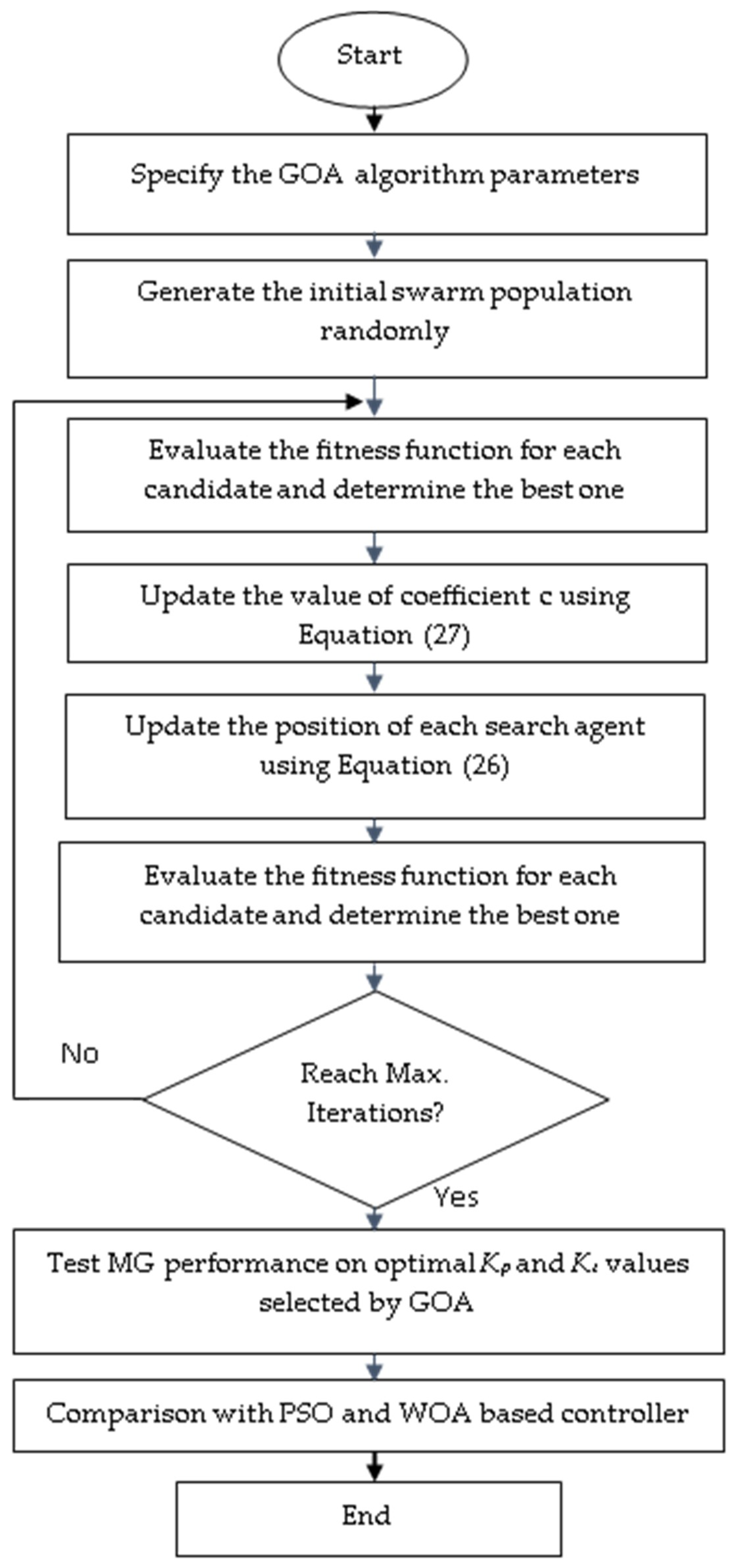
is the maximum number of iterations. A detailed flowchart of the GOA implementation in this study proposed MG controller is shown in
Figure 5.
At the start of the simulation, like all optimization techniques, GOA used to place some random particles in the search space whose boundaries are specified by the user. These particles are further moved in the search space according to the governing equations of the algorithm to optimize (minimize) the formulated cost function. In order to benchmark the performance of the GOA, a series of tests were undertaken by its developers [
10]. They compared the performance of the GOA with other well-known optimization techniques like GA, DE, and PSO, and concluded that the GOA balances the exploitation and exploration process better than its counterparts. Furthermore, the GOA algorithm has also recently been applied towards addressing important engineering problems like optimal distribution system reconfiguration and distributed generation placement [
11], the optimal allocation of compensators [
12], load forecasting [
13] and sizing of multiple distributed generation and battery swapping stations [
40]. These studies have validated the effectiveness of the GOA in solving optimization problems better than the conventional optimization techniques.
6. Results and Analysis
The GOA has been employed in this study for selecting the optimal values of PI controllers in an islanded MG system by minimizing the given objective function. The results were also subsequently compared with WOA- and PSO-based controllers for the same operating conditions. The modeling of the three-phase grid-connected VSI system along with the proposed controller has been undertaken in the MATLAB/Simulink version 2017a environment while the GOA, WOA, and PSO codes were implemented using the MATLAB editor for the minimization of the selected objective function. In order to undertake a fair comparison, the number of particles and iterations are set to be 50 for each of the GOA, WOA, and PSO algorithms. The search spaces of the optimized parameters Kpv, Kiv, Kpf, and Kif were then selected by the “trial and error” method in the range of 0 to 50. Two solar PV modules have been used; each with a power rating of 50 kW. The sampling frequency considered in the simulations has been 500 kHz which is equivalent to a sampling time of 2 × 10⁻⁶ s.
The model parameters include; Ls = 6 mH, f = 50 Hz, filter capacitance C = 3000 µF, and the input capacitor of the dc side is set to 15 mF. Each DG unit with a rating of 50 kW has been used. Furthermore, the current control parameters were set to Kp = 12.656 and Ki = 0.00215. For the SVPWM-based current controller, the switching and sampling frequency was fixed at 10 kHz and 500 kHz, respectively. The performance of the proposed controller has been examined and compared with PSO and WOA for the following two cases.
6.1. Voltage and Frequency Regulation during DG Insertion and Load Change
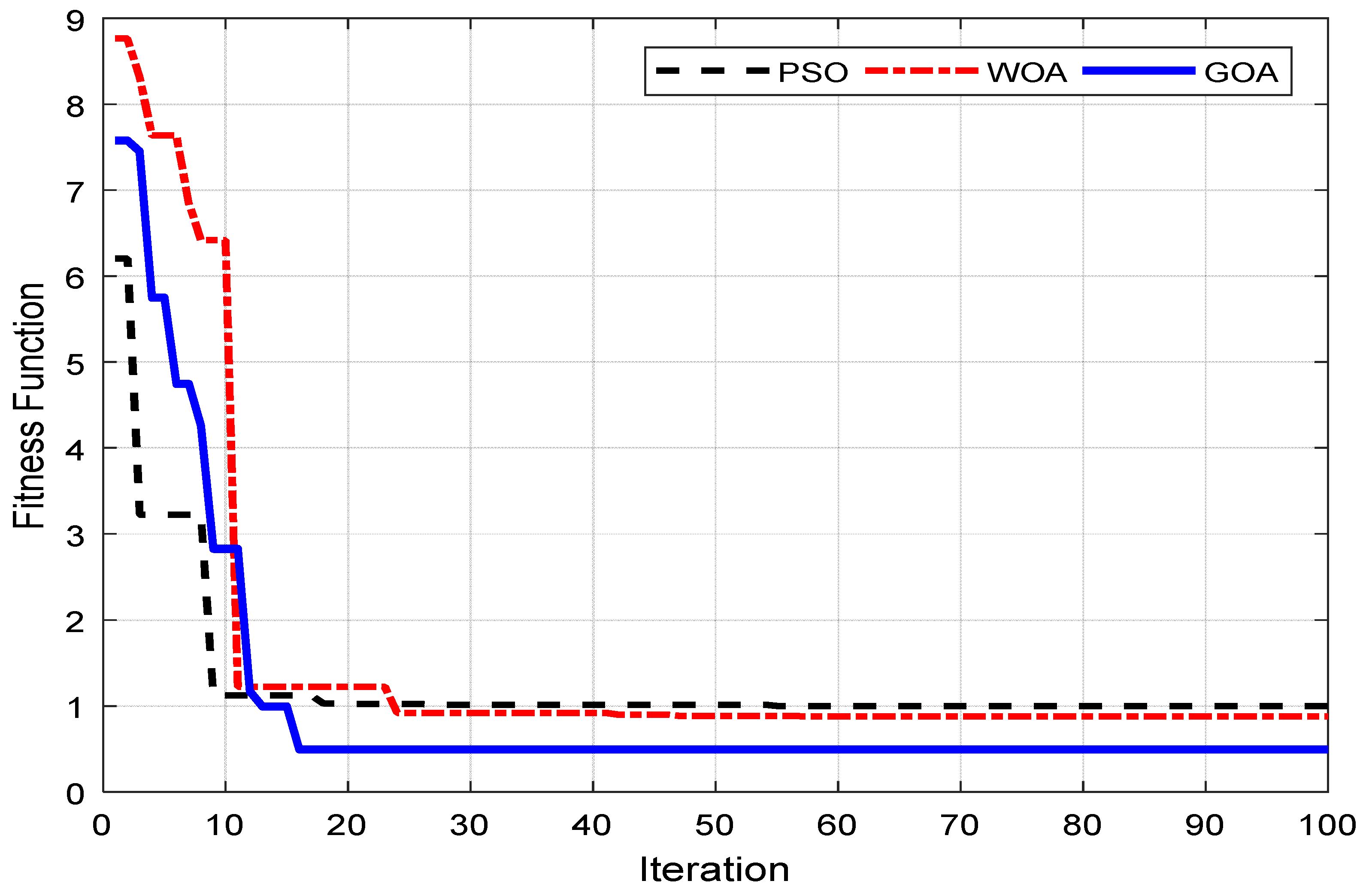
In order to minimize the voltage and frequency dips and to attain the nominal voltage and frequency of the studied MG system, both during and after the DG insertion and load increment, the proposed GOA-based controller was required to select the optimal gain values of the two PI controllers. This has been achieved by minimizing the FF using the intelligence of three different metaheuristic techniques (PSO, WOA, and GOA). Since the studied optimization methods are based on random number generations and basically stochastic in nature, the model was run 20 times to obtain the statistical data from results. The key objective has been to minimize the FF, and thus its minimum value has been taken as the best value. The convergence behavior of the three studied techniques (PSO, WOA, and GOA) under the same operating condition is shown in
Figure 6.
The two most important parameters of comparison from
Figure 6 are the final convergence value and the convergence rate. As such, the smaller the final obtained value of FF, the greater the performance of the controller. On the other hand, the greater the convergence rate, the greater the efficiency of the optimization technique towards attaining the optimal values of the controlled parameters. In offline optimization, the quality of the solution is more important compared to the rate of convergence. It is evident from
Figure 6 that WOA offers a better optimal solution than PSO; however, it has a slower convergence than that of PSO. In the meantime, it is found that the GOA based controller attains a faster and better optimal solution than both the WOA and PSO based controllers.
Table 1 provides the final optimized value and the number of iterations for which the minimized value of the FF has been obtained.
As the simulation is run; the optimization algorithm starts searching for the best combination of the control parameters which minimize the stated objective function and hence provide an optimal dynamic response of the system during MG insertion and load changes. This searching process halts once the minimized value of the objective function is obtained or the given iteration number has been reached. The searching process also halts once the optimization algorithm has run for 100 iterations. The final values of the four optimized parameters i.e., two gains of voltage PI controller (
Kpv and
Kiv) and two gains of the frequency PI controller (
Kpf and
Kif) under this study for each of the PSO, WOA, and GOA controllers are given in
Table 2.
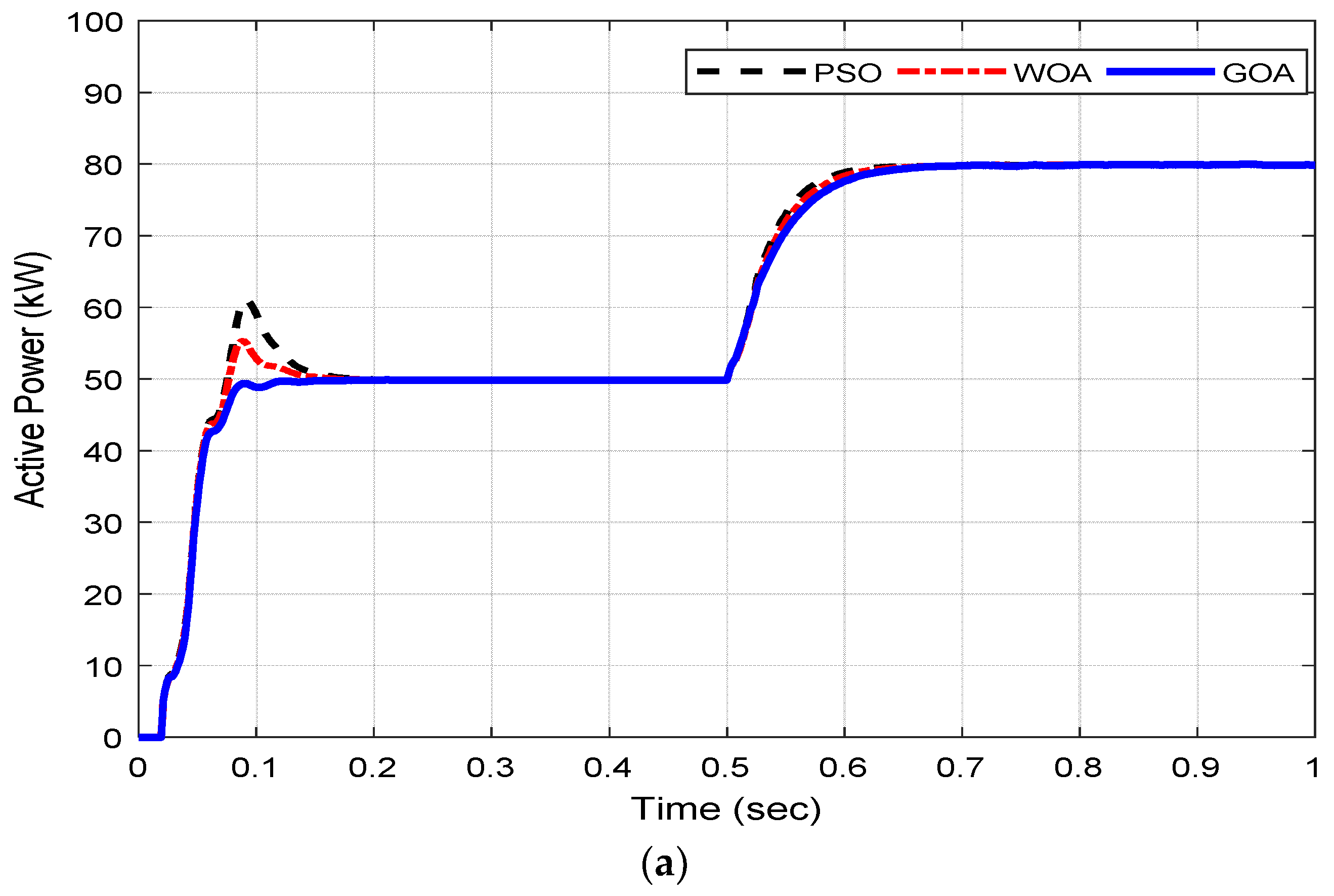
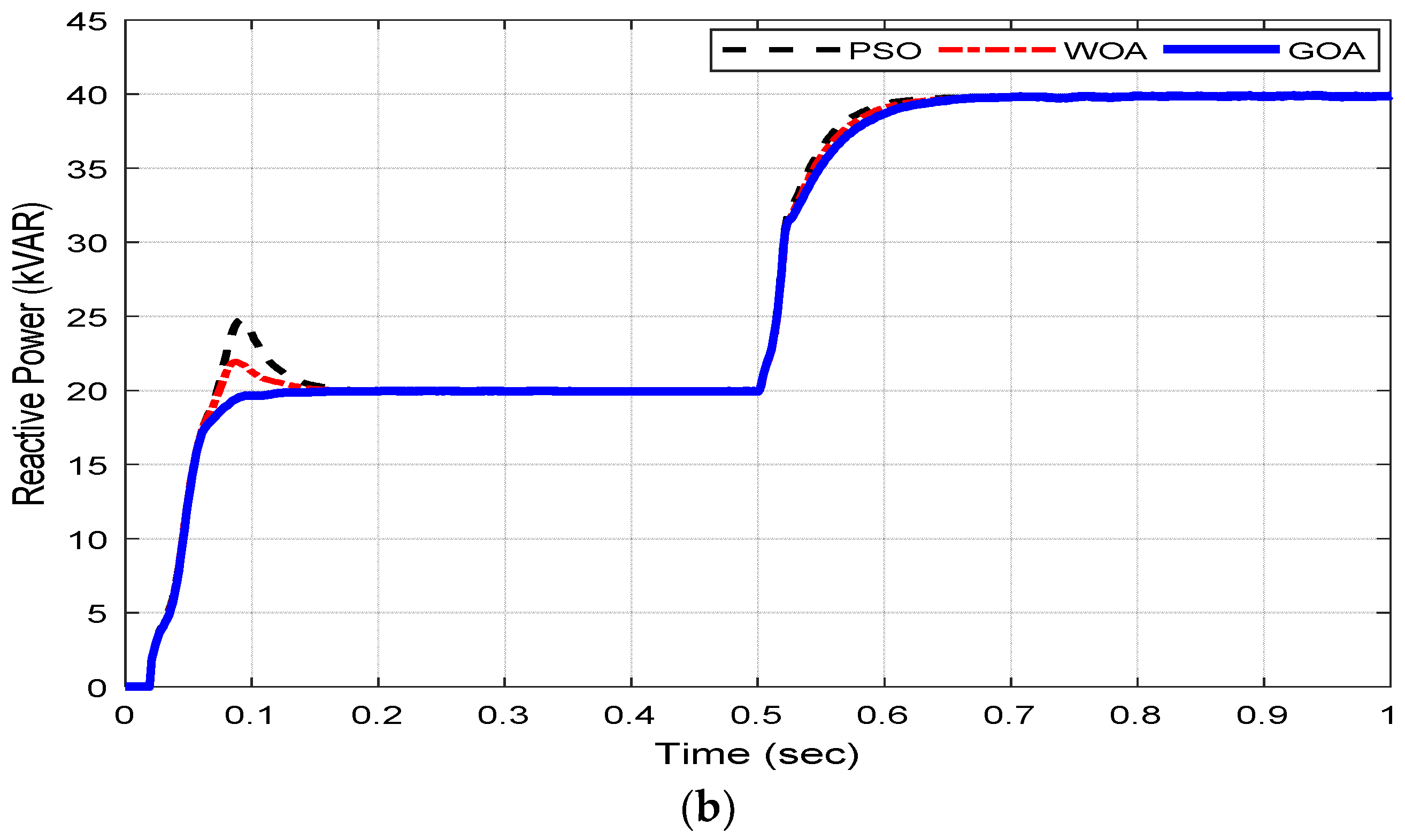
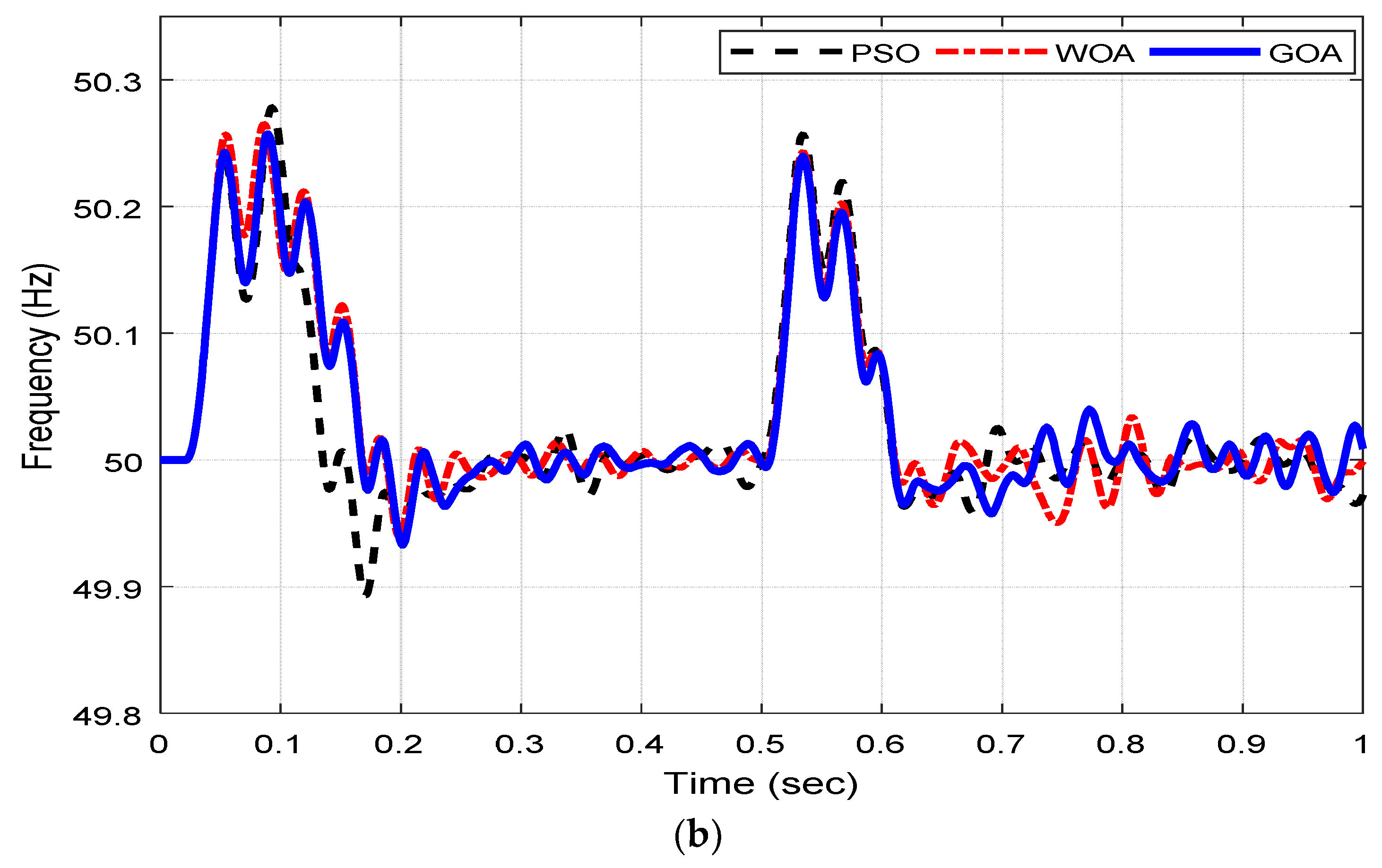
Further, the performance evaluation of the proposed control scheme was undertaken when the DGs were connected to supply a load of 50 kW (20 kVAR) at the start of the simulation. The DG unit adopts the v-f power control mode, based on the proposed control algorithm, in order to mitigate the voltage drop and avoid a severe deviation of the frequency caused by a sudden DG insertion. Subsequently, an additional load of 20 kW (20 kVAR) is inserted into the system at 0.5 s.
Figure 7 shows the comparison of active and reactive power variation between three different controllers under same operating conditions.
It is noted that as soon as an additional load of 20 kW, 20 kVAR is inserted into the system at 0.5 s, the voltage falls instantly due to the additional voltage drop across the load resistance and filter components. At this, the controller acts to restore the nominal voltage and frequency of the system immediately. It does so by sending the present value of the cost function from the SIMULINK model to the MATLAB workspace continuously after each 2 × 10
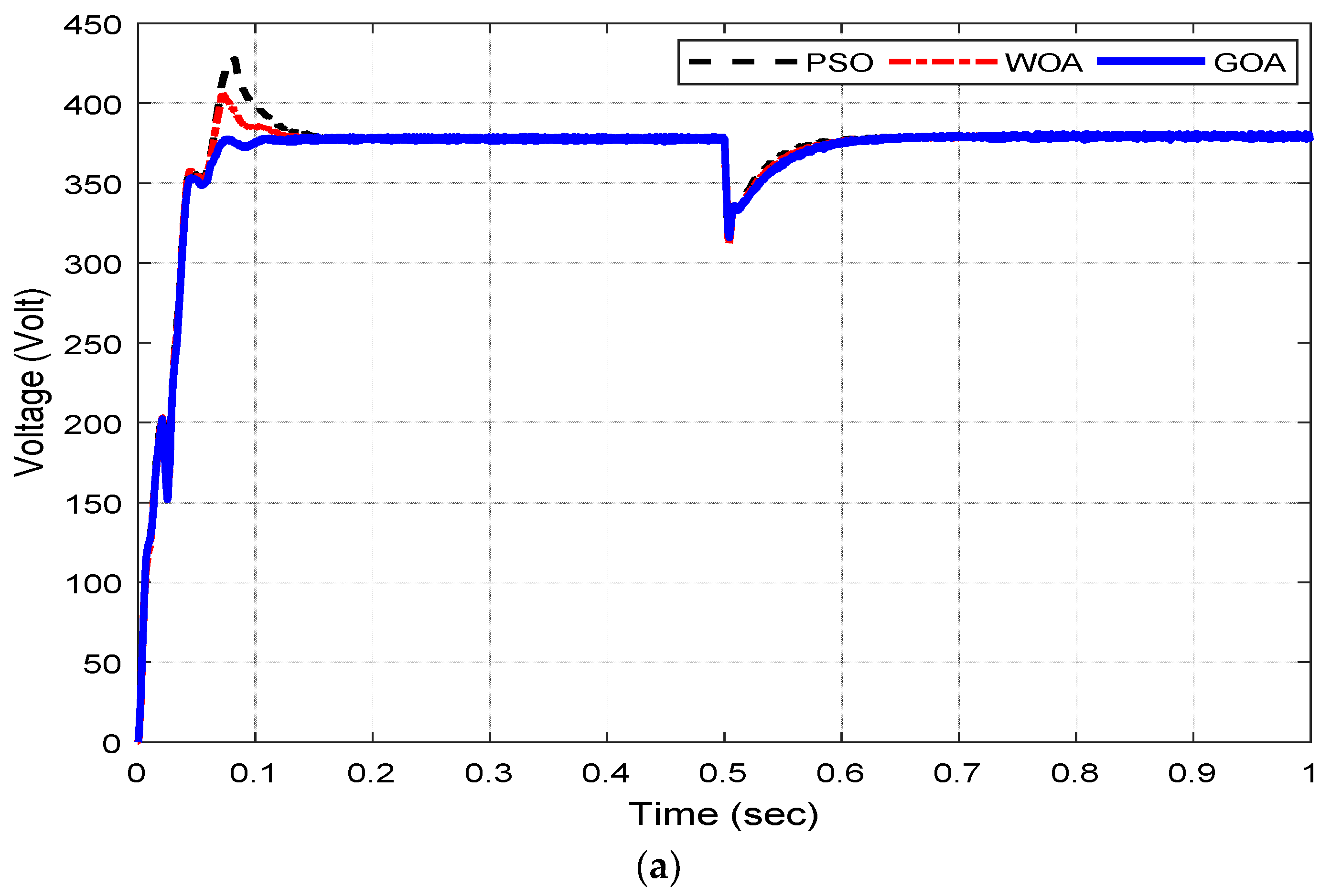
−6 s (sampling time), and the GOA optimizes the cost function according to the new values. The corresponding response of the MG system in maintaining the nominal voltage and frequency is shown in
Figure 8a,b.
It is evident that the GOA based controller offers better dynamic response and attains the nominal voltage (375 V) and frequency (50 Hz) in the minimum settling time and overshoot as compared to the PSO and WOA based controllers during initiation and load change condition. In addition, the obtained results are better than those of previous research work in the mentioned area of research. Unlike the previous studies, such as References [
3,
34], our proposed control strategy has managed to keep the frequency value within its ±1% tolerance limits as seen in
Figure 8b. Moreover, unlike the voltage control in Reference [
34] where an over-voltage of 20% has been observed during steady state condition (from 0.5 s to 0.7 s of the simulation), the proposed control strategy is able to reach and maintain its rated voltage within 0.07 s. The voltage and frequency control of an islanded MG using the hybrid Big-Bang Big-Crunch (BB-BC) and the Pareto based BB-BC algorithm has been studied in References [
14,
25] respectively. The developed control architectures have managed to keep the voltage and frequency well within the standard limits. However, after the DG insertion and load change, the frequency level was settled to a new value (59.7 Hz) after a decline of 0.5% from its rated value (60 Hz) in both case studies, which is not the case in this research work. Furthermore, in this research work, the higher active and reactive power levels (80 kW and 40 kVAR) are considered more than that of the previous research work. This implies that the proposed control strategy in this research work is more efficient, faster, and holds good for a high power penetration of DGs. Thus, the comparative analyses evidently acclaim the efficient and faster performance of the proposed control strategy. The percentage overshoot and settling time for each case is given in tabular form in
Table 3 as follows.
It may be noted that it is quite difficult, if not impossible, to attain such real-time online optimization, under different operating conditions, in practical applications due to a lengthy searching process, unpredictable load switching and simulation time. Therefore, in this study, the optimized parameters are selected using PSO, WOA, and GOA for the operating conditions, e.g., MG insertion and load changes throughout the simulation run. The key advantage of this method includes the smooth adaption of optimized parameters and more importantly, the obtained parameters hold good for all operating conditions. As the optimization algorithm code is run from the MATLAB editor, the applied algorithm starts searching for the optimal PI parameters by minimizing the cost function.
6.2. Dynamic and Steady-State Response
One of the major parameters which need to be taken care off during the islanded mode of operation is the sinusoidality of the inverter’s output voltage and current. This is because, unlike the grid-connected mode, in the islanded mode of operation, the grid remains disconnected from the MG and hence the control scheme is responsible for maintaining the power quality and harmonics free voltage and current waveforms.
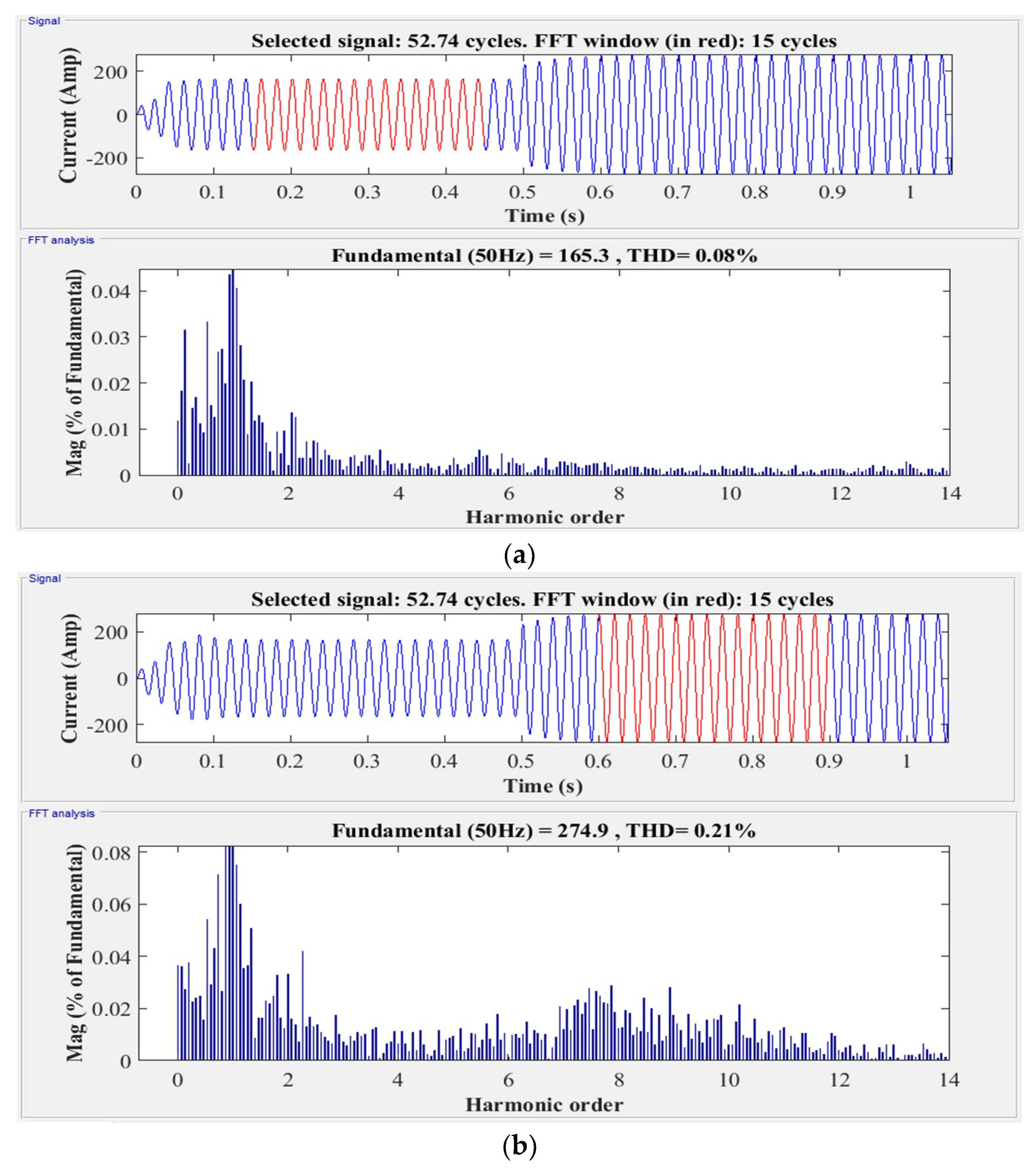
The optimal selection of the PI controller parameters ensures the pure sinusoidal waveform and hence minimum Total Harmonic Distortion (THD).
Figure 9 shows the Fast Fourier Transform (FFT) analysis of the output current waveform for the proposed controller after the DG insertion and load change. The FFT analysis of the output current waveforms shows that the GOA based controller provides an almost negligible THD which shows its effectiveness in regulating the voltage and frequency of the studied islanded MG system along with a high power quality. This is a very important characteristic of a controller especially when the MG is operated in the islanded mode of operation. This is because, in the absence of the main grid, it is completely the function of the MG controller to ensure the sinusoidal voltage and current waveforms with a high power quality.
Table 4 shows the comparison of the proposed controller with the PSO and WOA based controllers on basis of the output current waveform THD level for 15 cycles with a fundamental frequency of 50 Hz.
As per the IEEE standard 1547–2003 [
41] the allowable percentage (%) THD in the electric power supply must be less than the 5%. As it is seen from the
Table 4 that after the DG insertion, the %THD attained by the PSO, WOA, and GOA based controllers are 0.18%, 0.15%, and 0.08% respectively which are well within the set limit, thus validating the effectiveness of the proposed MG control architecture. However, by comparing these values with the standard limit of 5%, it is realized that the GOA based controller has produced a 2% and 1.4% more reduction in the %THD than those produced by the PSO and WOA based controllers, respectively. In the same way, after the load change, the %THD attained by the GOA based controller is 0.21% which is a 3.2% and 1% higher decrement than those produced by the PSO and WOA based controllers respectively. Hence, the GOA based controller provides a better optimal response with the least THD as compared to the PSO and WOA based controllers. In addition, the power quality obtained in this research work is much better than that of Reference [
34] as the %THD in output current waveform obtained in this work is 0.08%, which is less than 0.20% as observed in Reference [
34]. It is, therefore, established that the proposed controller with the GOA based parameter selection provides better dynamic response and power quality as compared to its counterpart AI based controllers under the same operating conditions.


