Article

Development of a Multi-Architecture and Multi-Application Hybrid Vehicle Design and Management Tool

1
DRIVE EA 1859, Univ. Bourgogne Franche Comté, F58027 Nevers, France
2
Femto-ST, UMR 6174, CNRS, Univ. Bourgogne Franche-Comte, F90010 Belfort, France
*
Author to whom correspondence should be addressed.
Energies 2018, 11(11), 3185; https://doi.org/10.3390/en11113185
Submission received: 8 October 2018 / Revised: 4 November 2018 / Accepted: 13 November 2018 / Published: 16 November 2018

Abstract

:
Hybrid electric vehicles (HEVs) are very promising sustainable mobility solutions. Series, parallel and series-parallel (SP) seem to be three most promising architectures among the multitude of hybrid architectures, and it is possible to find them in a multi-applications such as the motorcycles, family-cars, hybrid city busses and sport cars. It is import to have a well configured model in order to develop the different control strategies (CsTs) for each application. Therefore, a multi-architecture/multi-application (MAMA) approach capable of identifying the most energy efficient hybrid architecture considering both the dimensions of key components: electric motor (EM), battery, internal combustion engine (ICE) and the optimal control is presented. Basis of the model is the energetic macroscopic representation (EMR), which has been combined with object oriented programming (OOP) in order to enhance its modularity and reuse capabilities. The obtained results show, that different hybrid architectures are most adapted for different applications. Moreover, the robustness of the results using real time control algorithms are studied, showing that CsT matters. The obtained results contribute to simplify and harmonize the design of hybrid solutions for multiple applications.

1. Introduction

Humanity is using huge quantities of energy in order to maintain its lifestyle. This energy demand is increasing every year and the majority of energy comes from nonrenewable resources [1]. International Energy Agency (IEA) [2] shows that a considerable amount of 35% this energy is used for transportation and that Passenger Cars count for 21% of the total energy consumption. Two major problems are linked to the extensive use of nonrenewable energy sources: firstly, the use of nonrenewable resources creates combustion gases that change the composition of the atmosphere and contribute to the greenhouse gas effect. Those gases are called greenhouse gases [3]. Secondly, the resources of petrol, natural gas and coal are limited and most reliable sources forecast the remaining resources to last no longer than 50 years for both petrol and natural gas and 150 years for coal (ignoring all increases in consumptions) [4]. For those reasons, nonrenewable energy resources have to be replaced in the following years in all sectors of energy use.
Even though extensive efforts try to implement electric and hydrogen based cars [5], it can be seen that a simple replacement of energy sources is not an easy task to manage. If electricity is used to power a car, the question of energy supply has to be solved. This includes the question of the availability of electricity charging stations for cars, and the effect of a great number of electric vehicles on the power grid. Especially while the electrical energy grid itself is struggling to use more and more renewable resources. Moreover, electric vehicles have in general a limited driving range and drivers might suffer from range anxiety [6]. Hydrogen fueled vehicles have greater driving range, but there is only a small number of hydrogen fueling stations available now [7]. Moreover, as the most abundant source in the universe, hydrogen is not available on earth being its pure form and it is therefore an energy vector and has to be created from other sources namely using the electrolysis of water from renewable resources. However, for the moment the majority of hydrogen available on the market is created by natural gas or chemical industry [8].
Hence, the transition towards more adapted personal cars will most probably be stepwise. One important step will be the increase of energy efficiency and another step will be the step-by-step transition towards electric mobility. Both activities are combined in hybrid vehicles. There are at least two energy sources to compose a hybrid electric vehicle (HEV), and one or more of them provide energy in the form of electricity [9]. There exist multiple degrees of hybridization and hybridization architectures, which are presented in more detail in Section 3. However, it is interesting to see that hybridization is foreseen in multiple different applications ranging from hybrid motorbikes, via all kinds of hybrid cars from city commuters to sport utility vehicle (SUVs) up to hybrid busses and trucks. A huge effort is also done in order to hybridize construction vehicles [10].
For this reason, a modelling approach, which can be parameterized for different vehicle applications and different hybrid architectures, is needed. Moreover, this model has to be able to provide the best dimensioning between the different components of the propulsion chain. On top of this, the model has to integrate also the control of the different components inside the propulsion chain. For this reason, the development of a multi-architecture/multi-application (MAMA) system, able to identify the most energy-efficient hybrid architecture, is presented.
The energetic macroscopic representation (EMR) was identified as one of the most promising approaches for this task due to three main reasons: firstly, EMR is highly modular, secondly, an EMR model can be parameterized very easily and thirdly EMR allows to derive the control of a complex system by inversion based control (IBC).
Then, the object oriented programming (OOP) was decided to apply on EMR in order to reinforce the idea of modularity and parameterization whilst keeping the aspect of IBC. OOP based EMR also offers the possibility to share the knowledge more easily as different parts of the model are integrated in object libraries where objects can easily be linked.
The expected outcome of the modelling is twofold: firstly, it is foreseen to do a study including multi-applications such as the motorcycles, family cars, hybrid city buses and the racing cars with different hybrid architectures (multi-architectures) and to determine for every application which architecture and which dimensioning of traction chain components is the most energy efficient. Based on this, conclusions will be drawn which hybrid architecture is the most adapted for which type of vehicle. The second aspect is to take this theoretic most adapted solution and test it on different (realistic) driving cycles and using applicable (real time) control strategies (CsTs). Goal of this part is to analyze if the theoretic solution is also applicable in real life and if the results are robust even if driving conditions change with regard to the test case.
Section 2 will present different CsTs, and EMR will be introduced in Section 3. Section 4 and Section 5 introduce EMR modeling method and OOP programming approach. Section 6 presents the simulation process and the results of the work before conclusions and perspectives are presented in Section 7.

2. Hybrid Architecture & Energy Management

2.1. Hybrid Architecture

The HEV is a combination of traditional cars and electric cars. It uses both fuel energy and electric energy to drive the vehicle. From the perspective of power flow, these two power devices can be connected in several ways. The optimum energy distribution between EM and ICE as well as the recovery braking will significantly improve the power system efficiency.
Series Hybrid: Series HEV is presented by Figure 1a. EM works as the main power source to drive the transmission which is charged by the battery. ICE works as the secondary energy source in order to recharge battery by connecting the generator [11].
Parallel Hybrid: As presented in Figure 1b, for parallel HEV, both ICE and EM could drive the transmission which are mechanically coupled in several possible methods: pure ICE power, pure EM power or hybrid power. Meanwhile, the EM could work as an electric generator which is charged by ICE’s power or recovery braking power.
Series-Parallel (SP) Hybrid: For SP HEV shown in Figure 1c, the HEV powertrain uses two torque-couplers which are mechanically and magnetically connected. Therefore, the structure of SP HEV could have the advantages of both series hybrid and parallel hybrid. SP HEV has pure ICE driving mode that is not available in the series HEV. SP HEV also has an additional EM, which is mainly used as an electric generator compare to parallel HEV. However, the SP-hybird’s powertrain structure is more complex, making it more difficult to control [12].

2.2. Energy Management

CsT of energy management plays a particularly important role in a HEV because it is responsible for the energy distribution control based on the requirements of environment and driver. A study of different HEV CsT is presented by Zhang [13] which consists of the CsTs based on rules and optimization. Chrenko et al. [14] provided a classification work of different CsTs of HEV which is shown in Figure 2.

2.2.1. Deterministic Rule Based Control Strategy

The deterministic rules are designed based on the ICE fuel map, heuristic, human intuition and mathematical models. These rules are implemented by using the lookup table in order to distribute the required power between ICE and EM. The methodology of deterministic rule based (DRB) controller and its implementation on the HEVs is presented in [15,16,17,18,19]. The optimization method to evaluate the components’ size as well as the control parameters for different HEVs that allows to reduce the mean value of fuel consumption of the whole driving cycle, where the controller uses a DRB strategy, is introduced in [20,21,22]. Kongresi et al. [23] presented a HEV hardware-in-the-loop configuration method in order to evaluate the control parameters of DRB CsT.
A. Thermostat (on/off)
In our case, a dynamic-model of the lithium-ion battery model is created by using battery state of charge (SoC) as a parameter, which is used to judge the remaining electric energy inside of the battery [24,25], and can be expressed as:
  S o C = S o C i n i ( i b a t C b a t ) d t  
where S o C i n i represents battery initial SoC, C b a t is capacity in [Ah], and i b a t is current in [A].
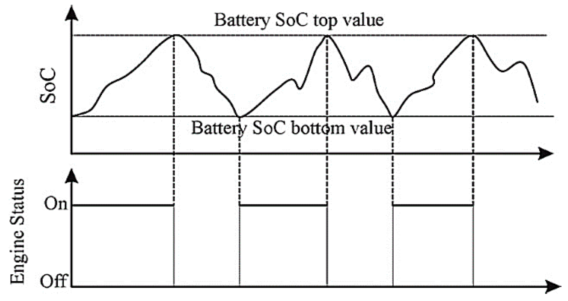
The thermostat CsT is based on the maximum and minimum threshold values of SoC to control the ICE by way of turning it on or turning it off. Therefore, the battery SoC will be maintained within a target range (Figure 3).
However, the thermostat CsT only takes into account the SoC without considering the demand power. Therefore, this strategy is more interesting for the city buses with a pre-planned simple driving cycle.
The thermostat CsT follows these rules:
-
If current SoC value is greater than predefined maximum SoC threshold value, ICE turns off;
-
If current SoC value is smaller than predefined minimum SoC threshold value, ICE turns on.
B. Power follower baseline
Its CsT is based on the HEV’s required power. The ICE is regarded as the principle energy source to drive the HEV and EM is used as the auxiliary energy source in order to assist ICE [27]. The following rules depict the baseline CsT:
-
Only EM works when current velocity of HEV is lower than threshold value;
-
If HEV needed power is greater than the maximum threshold value, the EM will be used to assist ICE;
-
Battery is charged by recovery brake energy;
-
ICE turns off if the HEV needed power is smaller than the threshold value;
-
ICE provides energy to charge the battery when current SoC is smaller than the threshold value.

2.2.2. Fuzzy Logic Rule Based Control Strategy

Fuzzy logic (FL): the predefined rules of CsT are based on the experts’ knowledge, driving experiences and human’s intuition. The precise input values will be first translated to fuzzy variables with the help of input membership function. Then these fuzzy variables will be disturbed by using the predetermined rules. Finally, the fuzzy output variables will be converted in order to defuzzification [28,29,30].

2.2.3. Equivalent Consumption Minimization Strategy Optimization Based Control Strategy

The energy consumed by the HEV (except for the recovery brake energy) needs to be compensated by the amount of fuel in the future driving. Therefore, an equivalence relationship between battery consumed energy and compensated fuel should be built and combined to a unique transient optimal control target.
According to the HEV actual operating state, in each control period to optimize in real time, the distribution ratio between required torque of ICE and EM is defined.
The general equation of transient equivalent consumption minimization strategy (ECMS) of HEV can be expressed as:
  J m i n = t = 0 p e r i o d { m ˙ f I C E · [ T I C E ( t ) , ω I C E ( t ) ] · Δ t + m ˙ f B a t _ e q · [ T E M ( t ) , ω E M ( t ) ] · Δ t }  
where m ˙ f I C E is ICE fuel consumption, m ˙ f B a t _ e q is the equivalent electric consumption, and t is the discrete time index [31,32,33,34,35,36,37].

2.2.4. Dynamic Programming Optimization Based Control Strategy

The dynamic programming (DP) algorithm as a global OB CsT, is regarded as an off-line CsT that needs the knowledge of the whole driving cycle. Therefore the DP CsT cannot be implemented for real-time control. However, its features of high accuracy can be used to act as the highest efficient CsT reference to compare with other real time CsTs.
The DP based HEV CsT needs to know the future driving conditions including vehicle speed, acceleration, stop time and slope of the road. If the future driving cycle is given, based on the time and space, the future driving trajectory can be divided into several interconnecting stages. The vehicle speed, battery SoC and other vehicle condition as the state variables can be defined and then the decision to separate the ICE torque and EM torque is made in order to obtain the best objective function, which is the minimum fuel consumption which can be expressed by:
  J m i n = m i c e + m b a t , e q  
Hence, the trajectory known HEV energy management strategy is a multi-stage chain structure decision-making problem.

3. Modeling Principle and Approach

3.1. Overview of Energetic Macroscopic Representation

The working principle of EMR is based on the action and reaction between each associated element. These elements can be modeled by using several methods which include the mathematical formulas, state models, bond-graphs, transfer functions, Petrinets, etc. [38]. The modification or addition of one EMR model do not affect other models. For example, it is possible to add one more type of battery as the sub-model without modifying other sub-models.
The IBC scheme is one of the advantages of EMR. By using the direct inversion rules of EMR, the IBC can be obtained which results in the control structure by using a maximum operation and measurements numbers.
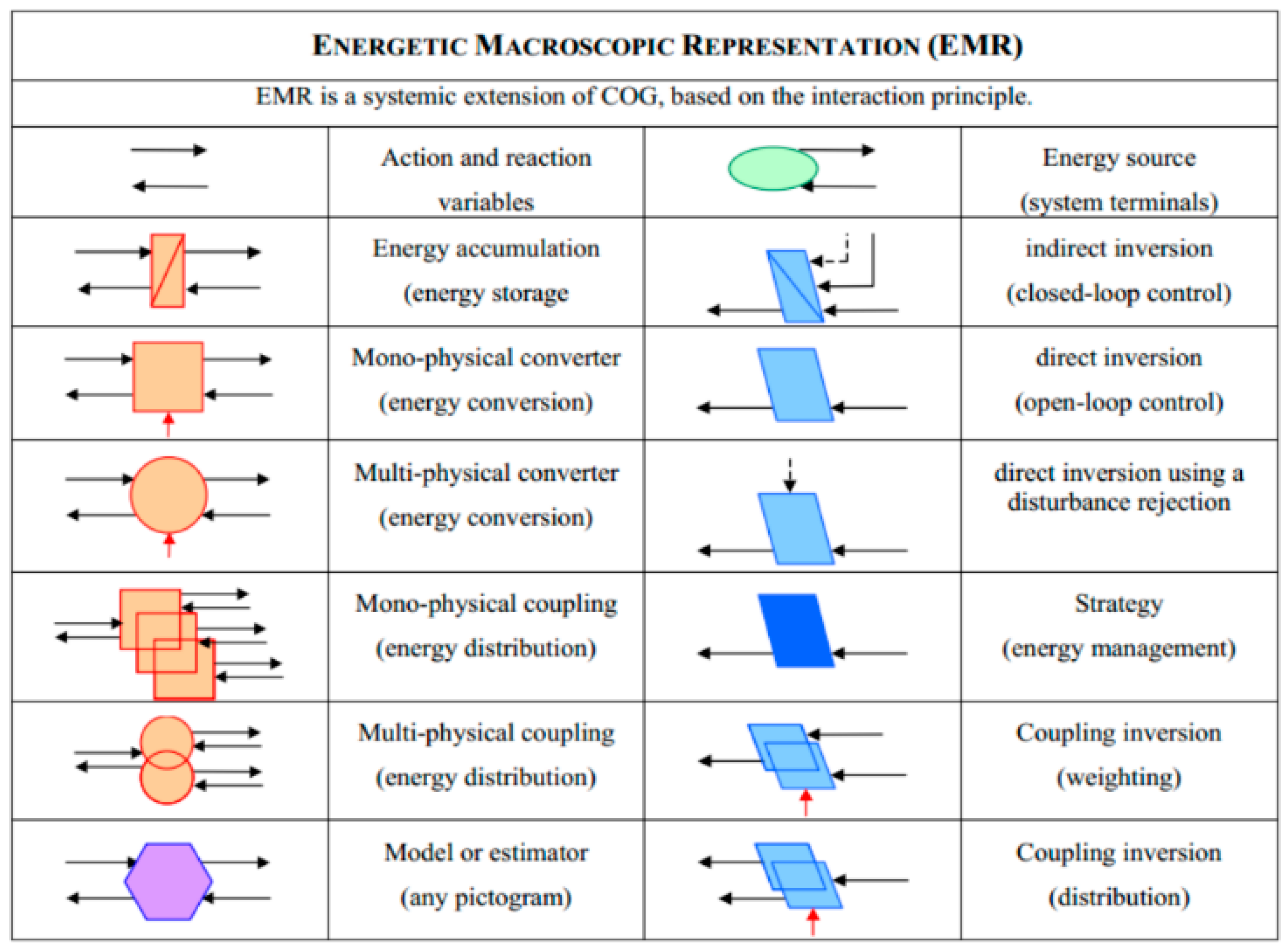
There are our types of blocks to compose the EMR model which represents four kinds of energy conversion forms. In addition, there are three kinds of elements which include energy flow, IBC and energy management. They are presented in Figure 4.

3.2. Multi-Architecture/Multi-Application Modeling Realization Using Energetic Macroscopic Representation

In order to create the MAMA tool of HEV, it is possible to separate the EMR model into two parts: structure for multi-applications and structure for multi-architectures.
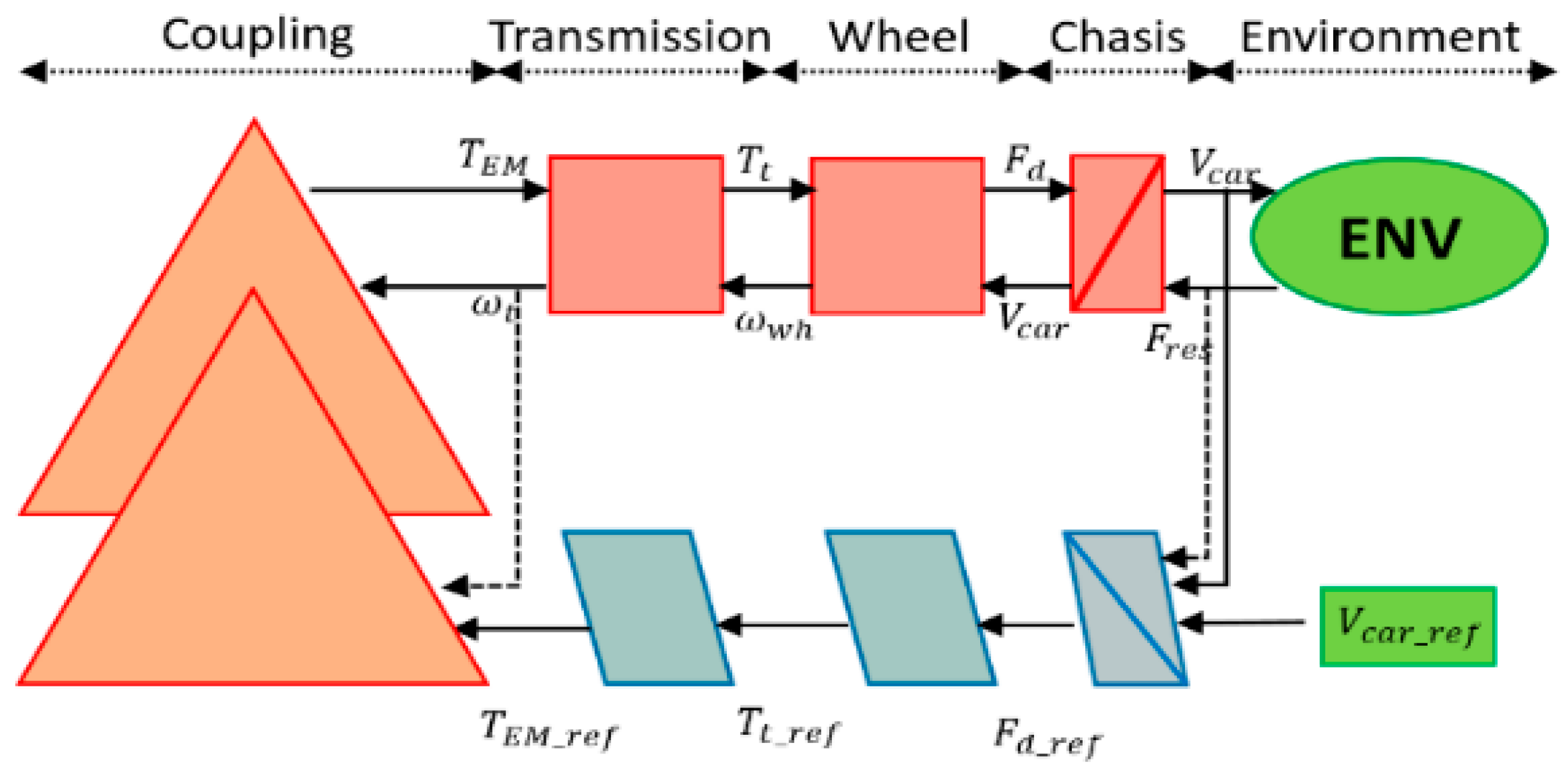
The structure for multi-applications after the torque-coupler is shown by Figure 5 which includes the elements of HEV source: transmission, wheel, chassis and environment source. This part is used to process the driving cycle data and calculate the required torque as well as the rotational speed. The structure of this part could be adapted for different types of vehicles by modifying the vehicles’ parameters such as the vehicles’ weight, wheel radius and rolling resistance coefficient.
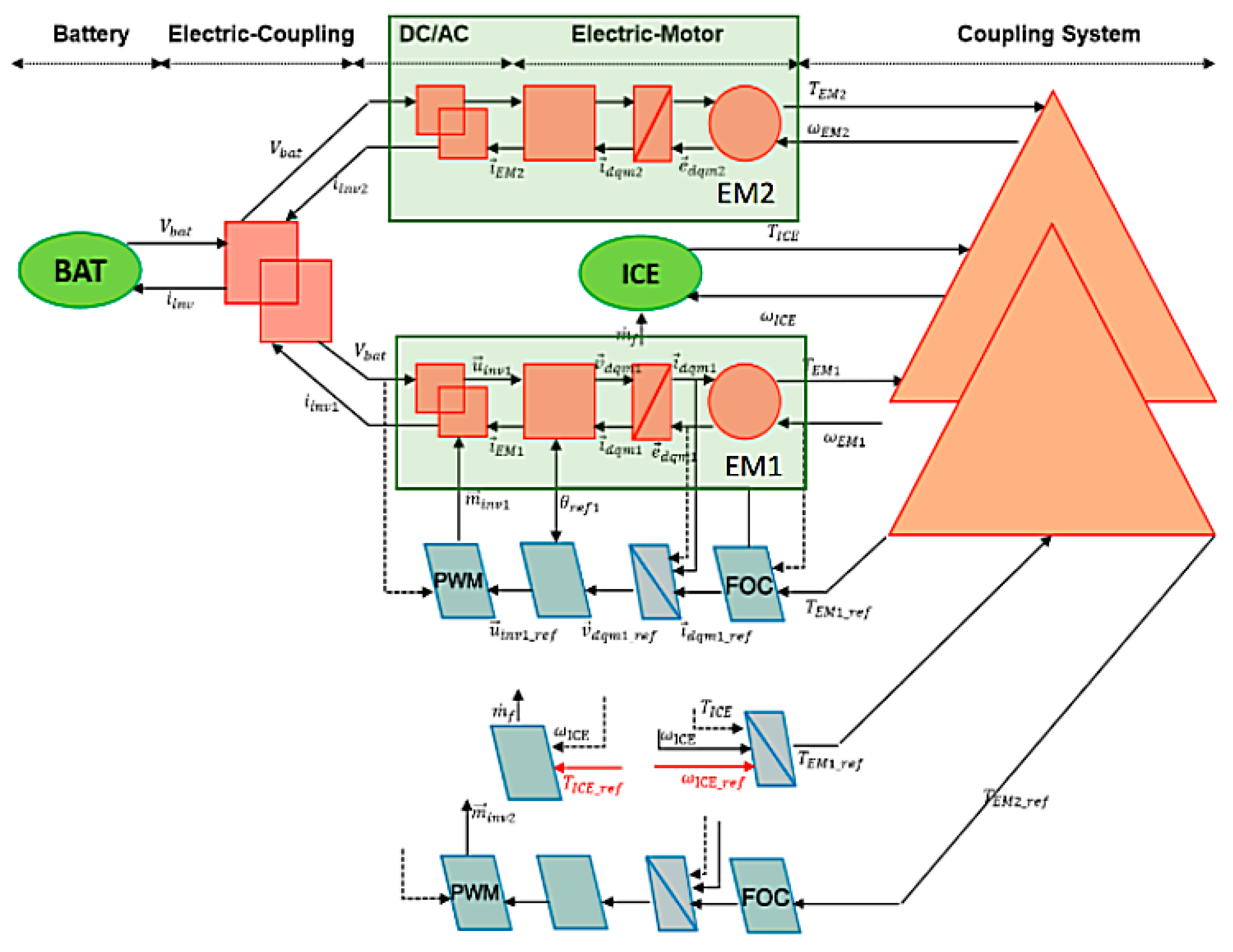
The structure for multi-architectures before the torque-coupler is presented by Figure 6. It consists of three energy sources of HEV (ICE, EM1 and EM2). By changing the ICE fuel map, EM efficiency map and the energy source parameters, this part could be used to represent different HEVs’ powertrains.
The torque-coupler system could be modified to represent three different hybrid architectures. The torque-coupler system can be seen as an interface between energy sources and vehicle sources.

4. Improvement of Modeling Using Object Oriented Programming

4.1. Overview of Object Oriented Programming

In order to improve the modularity and reuse of simulation, EMR is combined with OOP.
OOP is a method that considers the programming as an object which consists of the data, code and methods.
In our study, the modeling of OOP is developed based on the MATLAB 2013a version environment. Classdef is the keyword used to create classes in MATLAB. Properties are used to define the properties of the class, methods define the member functions of the class, and events block define the events of the class. In MATLAB OOP, the handle class is the base-class for all classes.
This section presents the HEV model creating using MATLAB OOP that has several advantages: First, the objective is to break the complex power system of a hybrid vehicle model into some basic parts. Secondly, the methods and the data are bundled into packages which makes modification easier.
Object is a specific element of the real world which includes the data and data operating methods.
Class is the summary of the commonness between specific and similar objects.
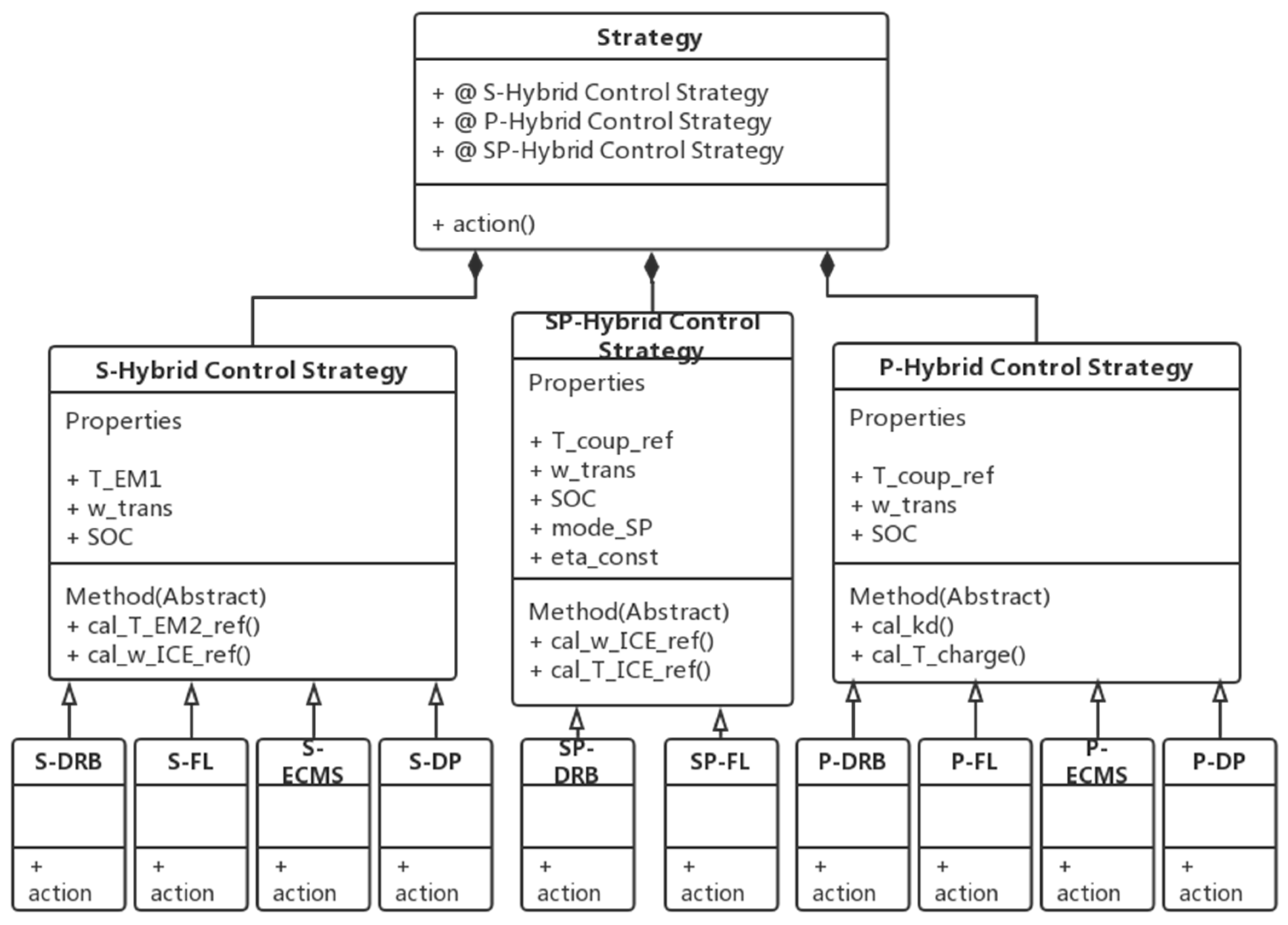
Unified Modeling Language (UML) is the graphs used to represent classes and objects, which is a graphical representation of the OOP. As presents in Figure 7, in the UML diagram, the class is presented by a rectangle which is divided into three parts. These three parts represent respectively the names of the classes, the variables and the methods.
Abstract class is used for the object which could not be instantiated. In the abstract class, the “function... end” form to define a method is not necessary. It only needs to provide the function a declaration form. In Matlab OOP, as soon as there is one method or property in a class, which is set to be “Abstract”, then this class is an Abstract class.
Class Composition means that the complex objects can be decomposed into several simple objects. In this way, in order to create some big and complex object, the process starts with the simulation of some the simple objects. Thereafter, these simple objects are assembled to form a complex object.
For example, as presented in Figure 7, the CsT OOP class consists of three sub-classes including S-hybrid, P-hybrid and SP-hybrid CsT(s). Meanwhile, these three sub-classes are also abstract parent classes, and four different CsT(s): DRB, FL, ECMS and DP are subclasses of them.

4.2. Realization of Object Oriented Programming

The realization of OOP models for all the components of HEV are presented in detail in [27] which include: environment (ENV), power transmission (chassis, transmission, wheel, torque-coupler), power resource (ICE, battery and EM/EG), energy control system.
ENV’s OOP models are used to calculate the environmental resistance to HEV which include the acceleration force, air drag and rolling resistance (Figure 8a). For the power source OOP model, The ICE’s OOP model is based on a fuel map, which helps to calculate the fuel consumption and ICE output torque. Thus in UML of ICE, the fuel map is embedded in OOP model as a constant property (Figure 8b). The OOP model of battery (BAT) use the inverter current as the input to calculate the battery SoC and voltage. UML property constants of the battery includes cell capacity, initial SoC, and battery charge/discharge resistance maps in Figure 8c.
The vehicle class is a base-class that contains three sub-classes which are transmission, wheel and chassis. Vehicle parameters need to be set for the transmission ratio, transmission efficiency (e_GT) and HEV quality related parameter (K_chas) as well as the PID controller parameters (PID_controller), which is shown in Figure 9.
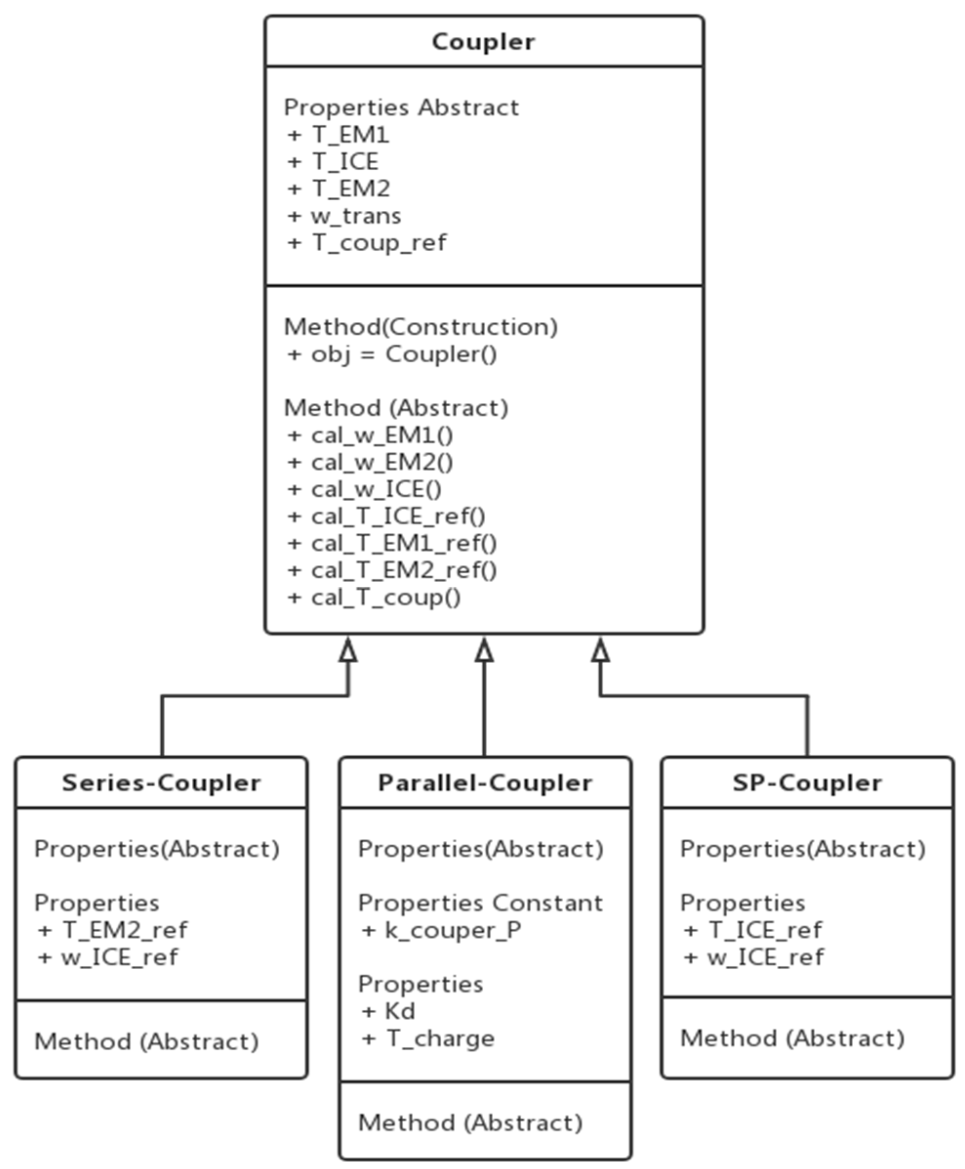
The abstract class of a coupler has three sub-classes which are series-coupler, parallel-coupler and power-split-coupler (Figure 10). These subclasses should have the same methods (functions): rotational speed and torque of EM1, EM2 and ICE. However, for each sub class, different input values will be needed. Apart from the properties abstract, series-coupler needs (T_EM2_ref) and (w_ICE_ref), parallel-coupler needs (kd) and (T_charge), SP-coupler needs (T_ICE_ref) and (w_ICE_ref) as the input values. These input values can be obtained by their CsT classes.
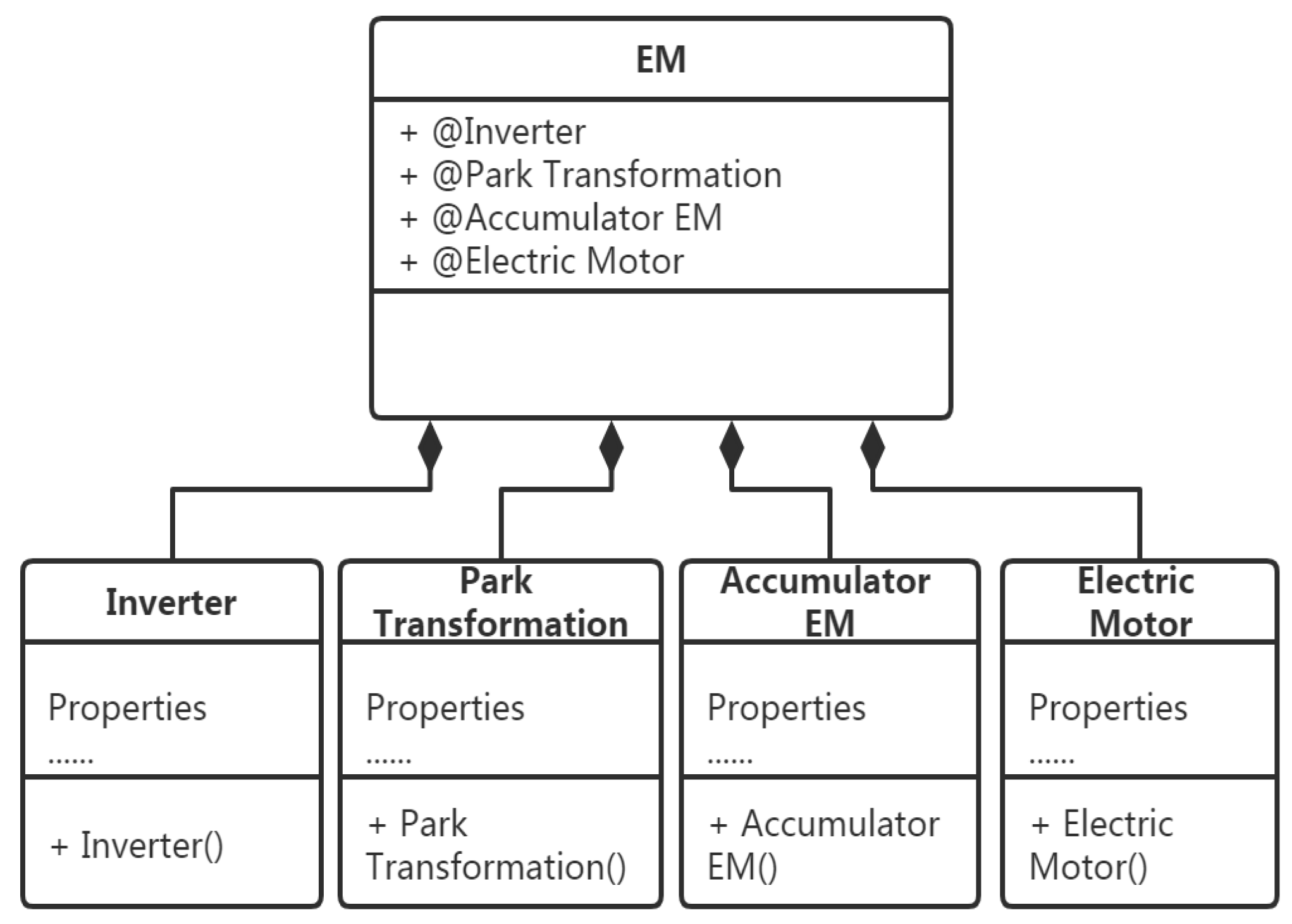
The permanent magnet synchronous machine (PMSM) is used as the EM and electric generator in the HEV model. In order to describe the energy flow go through the PMSM class, it can be divided into 4 subclasses: inverter, park-transmission, accumulator and motor. In base EM class, the constructor is called to create objects for inverter, park-transmission, accumulator and motor.
For different types of motors, different parameters and maps will be used. For the Inverter, the properties constants are rated power and inverter’s efficiency map. The properties constants of motor are EM efficiency map, friction map and poles number that should be set for different types of motors.
In accumulator, as it contains a PiD controller and a transfer function, so their associated control parameters are also embedded in its OOP model (Figure 11).
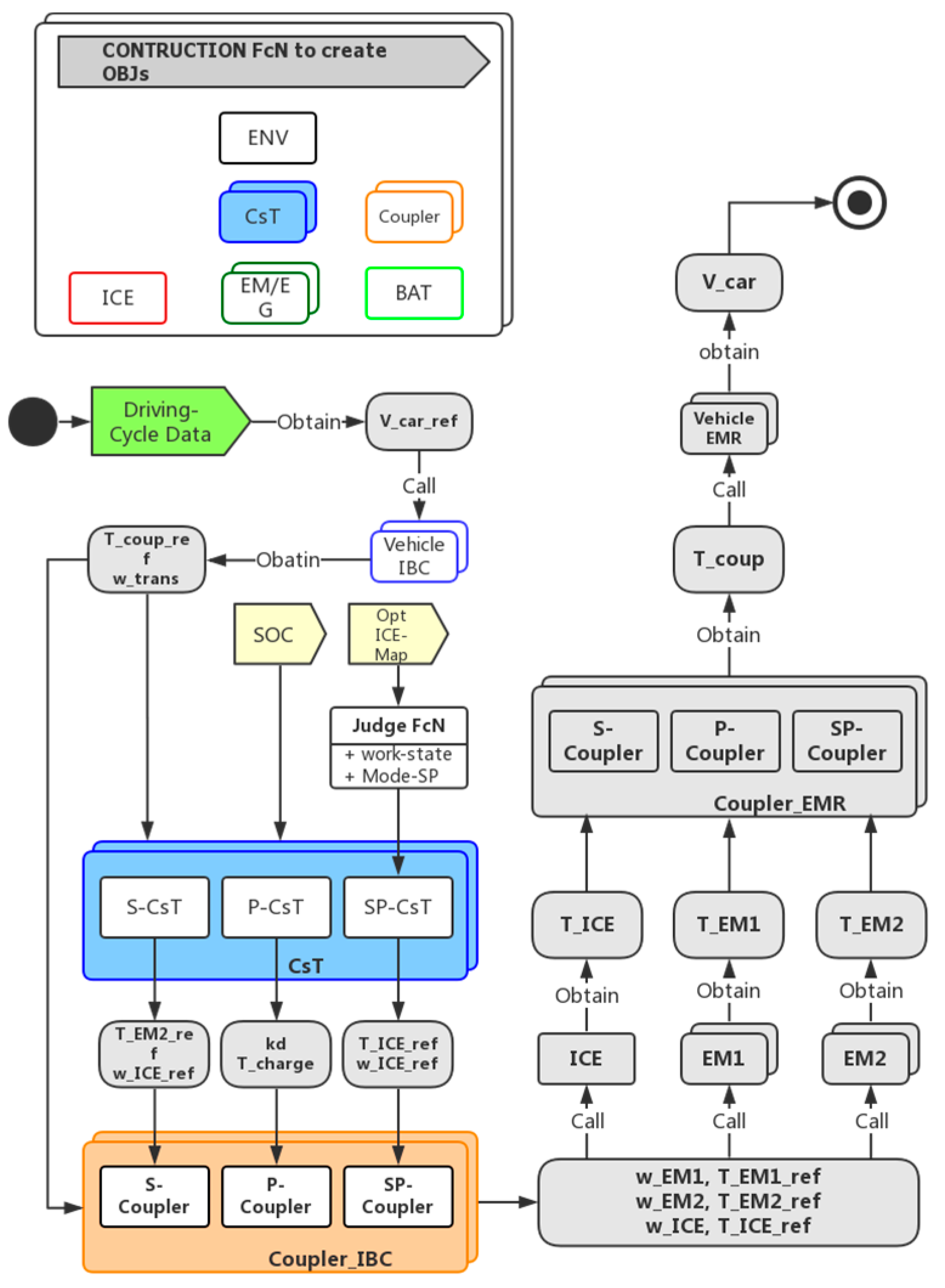
As Figure 12 shown, the main-program starts by the construction function in order to create the objects of HEVs’ elements.
Then three driving cycle data (WLTP, Artemis-Urban and Circuit-Magny-cours) will be loaded into the main-program which is the reference speed values.
After that, the vehicle object class calculates the torque needed by transmission by using these speed values.
Next, different control-signals will transfer from CsT-class to local-controller of coupler-class in order to obtain the ideal input signals for power-sources.
These ideal input signals will enter to power sources’ objects to calculate the actual output values.
Finally, the real current vehicle speed will be calculated by vehicles’ object.

5. Optimization for Power Source Resizing

This section describes the use of particle swarm optimization (PSO) for sizing energy sources in HEV that enables obtaining the optimal sizing required for different types of vehicles and different driving cycles, independently of the chosen energy management strategy.
PSO is an algorithm based on a model to simulate the movement of a group of birds (Figure 13). The principle of PSO is to move the whole population in order to find its best position p k g . The movement of the population as well as its particles are according to velocity formula ( v k i , v k + 1 i ) and position formula ( x k i , x k + 1 i ).
  v k + 1 i = w v k i + c 1 r a n d ( p i x k i ) Δ t + c 2 r a n d ( p k g x k i ) Δ t  
  x k + 1 i = x k i + v k + 1 i Δ t  
where w represents the inertia coefficient, c 1 is the self-confidence coefficient, and c 2 is the swarm-confidence coefficient [26]. In our study, the PSO tool is developed based on the MATLAB 2013a version environment.

5.1. Optimization Process

Figure 14 is the PSO simulation plan flow chart: there are four vehicles’ models to be optimized. Each model has three architectures: S-hybrid, P-hybrid and SP-hybrid. S and P-hybrid include three parameters to be optimized: P_(rated_EM), n_cell and V_d, SP-Hybrid has one more optimization parameter which is the gear ratio.
Theoretically, DP represents the optimal CsT as the reference CsT for PSO simulation. WLTP is a comprehensive driving-cycle that includes the urban, ex-urban and highway driving. It presents a comprehensive view of working conditions for motorcycles and family cars. Noao is a hybrid sports car, Raceway is its target driving cycle, so its PSO simulation are realized using raceway driving-cycle. The BYD-K9 hybrid bus is mainly driven in urban areas, thus the PSO simulation is realized using Artemis-Urban.

5.2. Optimization Results

After 12 PSO simulations, Table 1 presents the optimization results for these four vehicles models.

6. Simulation for Different Control Strategies

6.1. Simulation Process

After the PSO Simulation, the optimal dynamic parameters for each vehicle model can be determined. This section uses these parameters to perform a series of simulations in order to test four real time CsTs (RB, FL, ECMS) for each vehicle (Aprillia, CT6, Noao and K9) together with their three architectures (series, parallel and SP HEV) with regard to fuel consumption and power performance.

6.2. Simulation Results

Table 2 shows the fuel consumption result of three hybrid architectures for the four vehicles models, driving on their most suitable driving-cycles using their best CsTs. Based on the result, we can find that: when the motorcycle Aprilia-RSV4-RF-2017 is running on a comprehensive driving-cycle WLTP, S-Hybrid can achieve the minimum fuel consumption. When the family car (CT6) is driving on the WLTP, the minimum fuel consumption is 5.12 L/100 km, which appears also in an S-hybrid architecture. When Noao is driving on the race-way driving-cycle, the minimum fuel consumption appears in SP-hybrid architecture, which equals to 5.48 L/100 km. For the bus model (BYD-K9) running in Artemis-urban cycle, the best architecture is SP-hybrid with fuel consumption equals to 13.94 L/100 km.
It can thus be concluded that there is not one most adapted vehicle architecture, but different vehicle architectures are adapted for different vehicles running on different driving cycles. From the results, we can find that both vehicles on miscellaneous driving cycle WLTP lead to S-hybrid architectures. The fact that the two other vehicles lead to SP-hybrid architecture might seem surprising at first glance, as they use race and urban driving cycles. However both race and urban driving cycles distinguish themselves by their high dynamic aspect including many acceleration and deceleration phases.
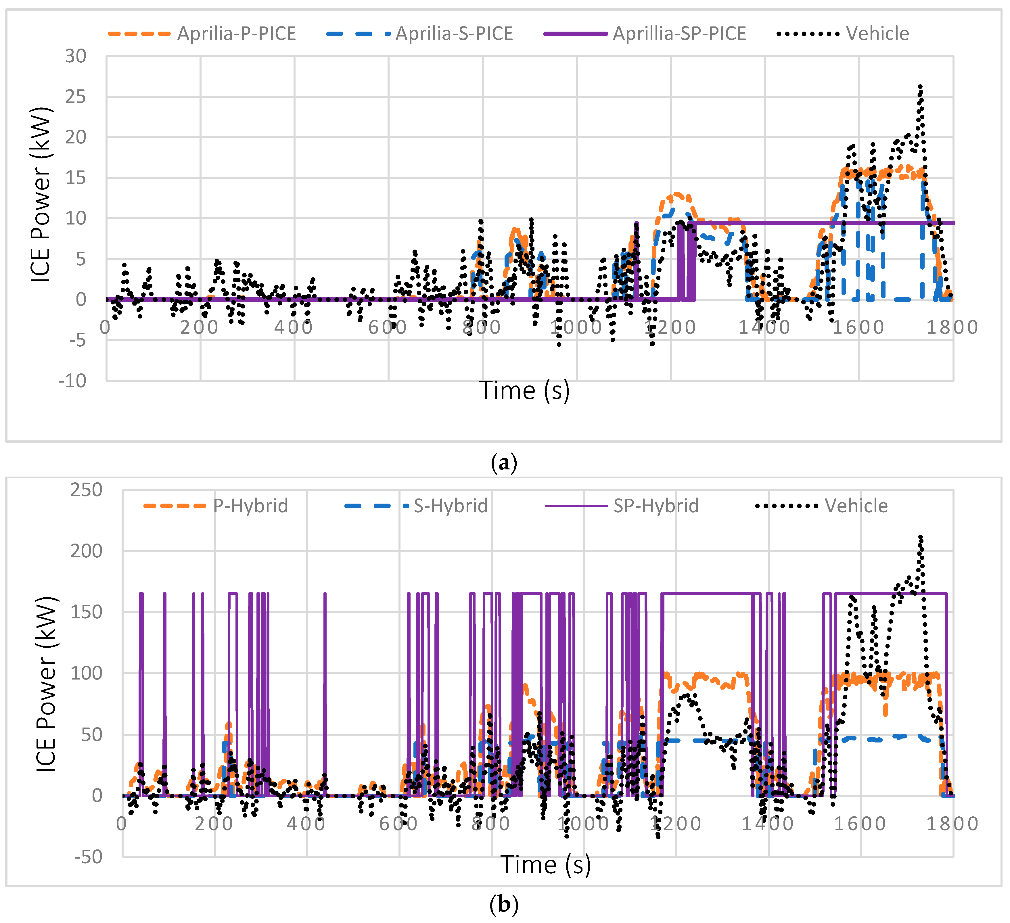
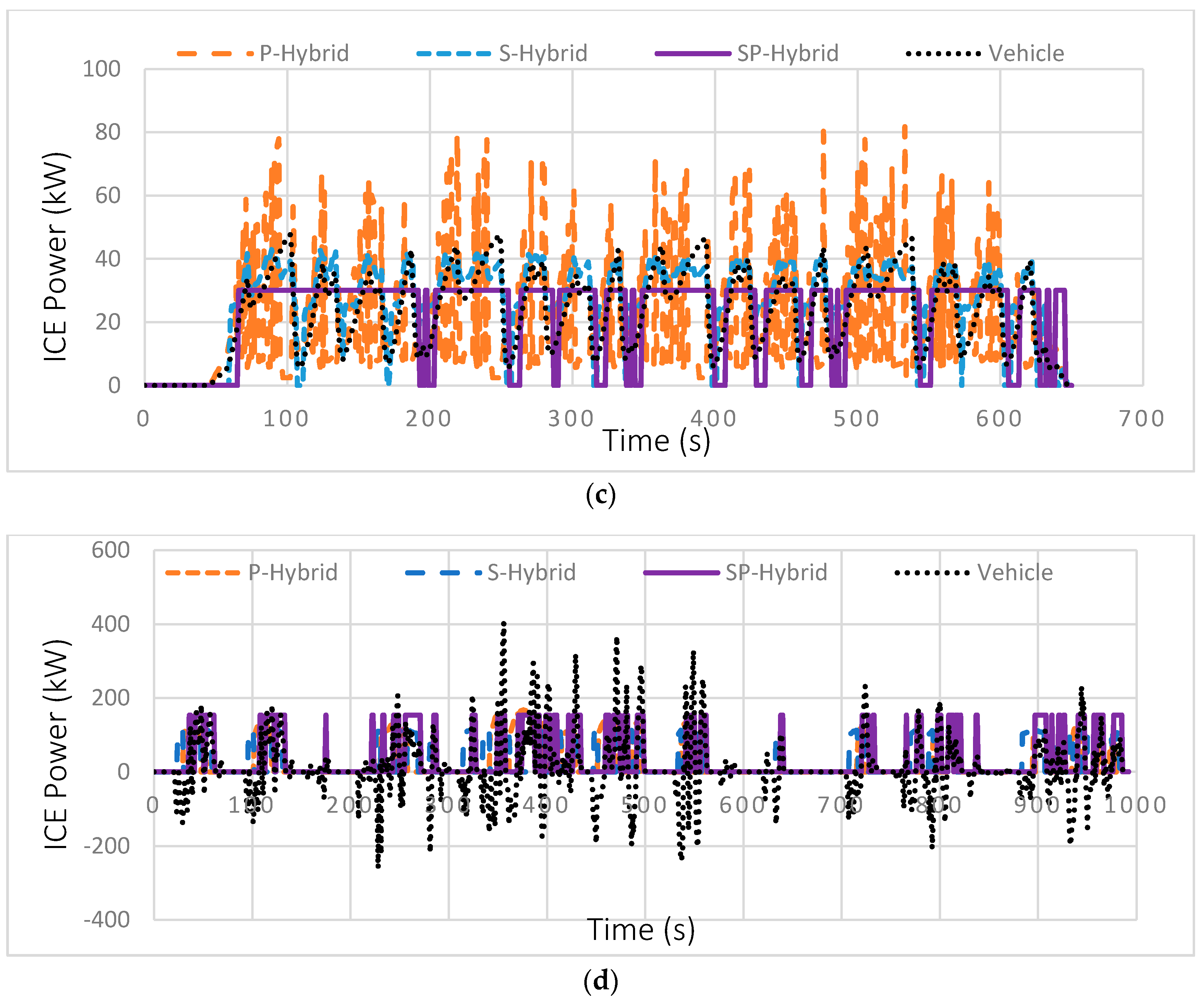
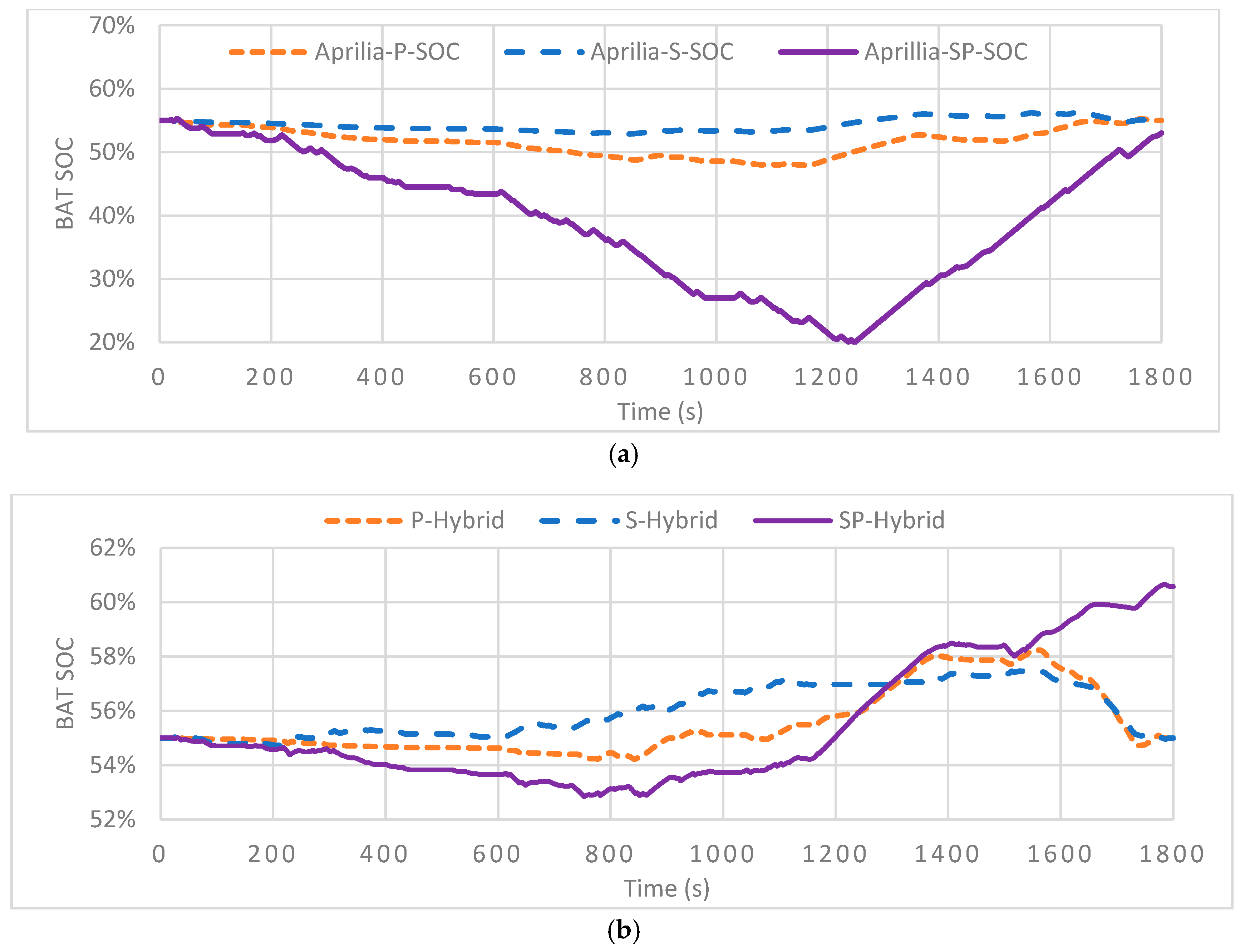
In order to analyze these results in further detail, ICE power distribution and battery SoC curves are presented hereafter in Figure 15 and Figure 16. The ICE power can be expressed:
  P I C E = T I C E _ r e f · ω I C E  
where T I C E _ r e f and ω I C E are the reference torque and rotational speed of ICE which is determined by the global CsT. Moreover, the variation of SoC can be calculated by Equation (1).
(1)
First of all, Aprilia-RSV4-RF-2017, representing a motorcycle driven on a WLTP driving-cycle (Figure 15), ICE power distribution for three architectures (Figure 15a and Figure 16a) show the ICE power distribution and battery SoC variation.
It can be found that for S and P hybrids, the variation of the output power of ICE are proportional to the required power. Meanwhile, ICE output power in the P-hybrid is slightly larger than in the S-hybrid.
The SoC variation of the S and P hybrid is relatively flat; their SoC curves keep fluctuating at a small range of 55%, but the SoC curve of SP-hybrid first drops to 20% and then rises back to 55%. Based on the above analysis, the reason that S-hybrid has the best fuel consumption performance in WLTP is explained by its SoC curve that varies most gently, the battery charging frequency and power are relatively low, thus limiting charging and discharging losses.
(2)
Then, the CT6 representing a family car driven on WLTP driving-cycle: Figure 14b and Figure 15b show the ICE power distribution and battery SoC variation.
We can see from the results that the variation of these figures are basically the same as the Aprillia driving on the WLTP. Because the optimal size of ICE is relatively large in the SP-hybrid architecture of CT6, its optimum output torque and rotation speed are large. Therefore, for SP-hybrid, the battery’s final SoC is also relatively large. Based on the same reasons as Aprillia, S-hybrid had the best fuel performance with CT6 running on WLTP.
(3)
Next, for Noao representing a race car driven on raceway driving-cycle: Figure 14c and Figure 15c show the ICE power distribution and battery SoC variation.
From the figures, we can see that ICE started very frequently in SP-Hybrid, S, and P-hybrid ICE output power varying in direct proportion to vehicle required power. SP-hybrid’s ICE output power remains constant around the best operating point. The SP-hybrid has the lowest peak power, but its power is always maintained at a constant value. S-hybrid has a slightly lower ICE peak power than P-hybrid, and the power curve always fluctuates within a range. P-hybrid has the highest ICE peak power, but it also has the largest fluctuation range. This could explain why the best fuel consumption performance occurs in SP-hybrid architecture.
(4)
Finally, the BYD-K9 bus representing a city bus driven on urban driving-cycle: Figure 15d and Figure 16d show the ICE power distribution and battery SoC variation.
From the figures, it can be seen that for the S and P-hybrids, the overall trend of their SoC curves are same. They first fluctuate within a certain range, then ICE charges the battery and increases the SoC dramatically; finally, the battery discharges to satisfy the power demand that makes SoC drop significantly. However, the overall trend of SP-hybrid’s SoC variation is slowly rising.
We can observe that the output values of the ICE power are greater than those for the other two hybrid architectures, and the ICE does not have repeated fluctuations, always maintaining a constant value.
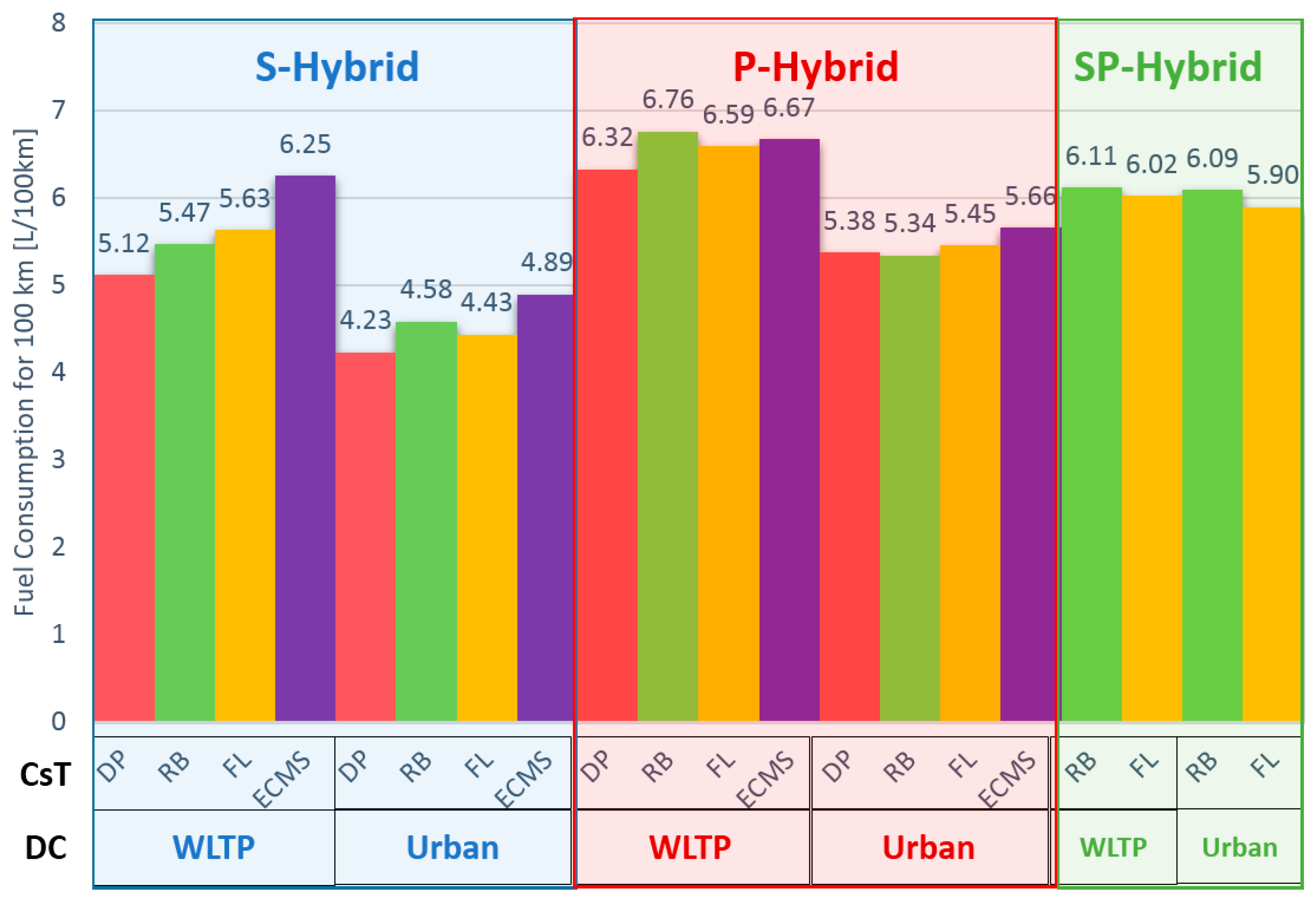
To better study the family car running on comprehensive and urban driving cycles, the three architectures of CT6 running in WLTP and Artemis-Urban driving cycles are studied in more detail, as shown in Figure 17. Using four kinds of strategies for control, and considering DP as the reference strategy, it is possible to study which real time CsT seems to be most adapted.
In conclusion, it can be said that detailed analysis showed that the use of ICE, according to the different CsTs, varies quite significantly. DP is, as expected, the best CsT, followed by RB and FL. They show little difference, which is not surprising, as they are both based on the same set of rules. ECMS, as used in this case, is the least adapted CsT. Moreover the energy split between DP and ECMS differs quite significantly, where DP tends to use the ICE for longer periods and at reduced power levels, while ECMS seems to suggest the opposite. However, in our case, a penalty fuel consumption for ICE start was not integrated, and it would be interesting to analyze its influence on the results.

7. Conclusions & Perspective

The objectives of this work are to create the multi-architecture and multi-application HEV model that can be parameterized for different vehicle applications and different hybrid architectures. This model is useful for optimization of vehicle components sizing, best CsT design, fuel consumption analysis and performance observation.
Thirteen different CsTs for the HEV energy management are presented and a focus on the implementation of four control-strategies has been done. The four strategies applied to HEV energy management control are: DRB, FL, ECMS and DP.
The model is based on the EMR principle using OOP, then the PSO is proposed to locate the best architecture as well as components sizing for given HEV. With the help of PSO’s results, the optimum parameters are used for control-strategy simulations. Four types of HEV (motorcycle, family car, racing car, bus) with three architectures (series-hybrid, parallel-hybrid and SP-hybrid) are simulated in three kinds of driving-cycles (comprehensive, urban, race-way) in order to analyze most adapted architectures, showing that different hybrid architectures seem to be most adapted for different use cases.
MAMA system is instructive for industry that could be useful for optimization of vehicle components sizing, best CsT design, fuel consumption analysis and performance observation, etc. Thus, in the future after applying this approach to different systems, it could be interesting to build a rapid prototyping tools based on this tool.

Author Contributions

S.G. developed the MAMA system as part of his Ph.D work supervised by D.C., A.K. and L.L.M.; all the authors discussed the documents results and contributed to the preparation of the manuscript.

Funding

This research received no external funding.

Acknowledgments

Administrative and technical support given by the laboratory DRIVE.

Conflicts of Interest

The authors declare no conflicts of interest.

References

  1. Enerdata. Global Energy Statistical Yearbook 2017; Enerdata: Grenoble, France, 2017. [Google Scholar]
  2. International Energy Agency (IEA). Key World Energy Statistics; IEA: Paris, France, 2017. [Google Scholar]
  3. Rate, P.E. Fuel Consumption Modeling of Conventional and Advanced Technology Vehicles in the Physical Emission Rate Estimator (PERE) Draft; EPA: Washington, DC, USA, 2005. [Google Scholar]
  4. BP Statistical Review of World Energy; British Petroleun Company: London, UK, 2017.
  5. Kwon, J.; Wang, X.; Ahluwalia, R.K.; Rousseau, A. Impact of Fuel cell System Design Used in Series Fuel Cell HEV on Net Present Value (NPV). In Proceedings of the 2011 IEEE Vehicle Power and Propulsion Conference, Chicago, IL, USA, 6–9 September 2011. [Google Scholar]
  6. Barré, A.; Suard, F.; Gérard, M.; Riu, D. Battery Capacity Estimation and Health Management of an Electric Vehicle Fleet. In Proceedings of the 2014 IEEE Vehicle Power and Propulsion Conference (VPPC), Coimbra, Portugal, 27–30 October 2014. [Google Scholar]
  7. Alexander, D.; Gartner, J. Electric Vehicles in Europe: Gearing Up for A New Phase; McKinsey & Company: New York, NY, USA, 2012. [Google Scholar]
  8. Hodkinson, R.; Fenton, J. Lightweight Electric/Hybrid Vehicle Design, 1st ed.; Hill, J., Ed.; Butterworth Heinemann: Oxford, UK, 2001. [Google Scholar]
  9. Maggetto, J.V.M.G. Electric and Electric Hybrid Vehicle Technology: A Survey. In Proceedings of the IEE Seminar Electric, Hybrid and Fuel Cell Vehicles (Ref. No. 2000/050), Durham, UK, 11 April 2000. [Google Scholar]
  10. Fuhs, A.E. Hybrid Vehicles and the Future of Personal Transportation; CRC Press: Boca Raton, FL, USA, 2009. [Google Scholar]
  11. Naumann, S.; Büchter, H.; Janecki, R.; Karon, G.; Sierpinski, G. Models and Methods for the Evaluation and the Optimal Application of Battery Charging and Switching Technologies for Electric Busses. 2014. Available online: http://www.cactus-emobility.eu/CACTUS_Deliverable_3.1_Methods.pdf (accessed on 16 November 2018).
  12. Zhang, P.; Yan, F.; Du, C. A comprehensive Analysis of Energy Management Strategies for Hybrid Electric Vehicles Based on Bibliometrics. Renew. Sustain. Energy Rev. 2015, 48, 88–104. [Google Scholar] [CrossRef]
  13. Zhang, M. HEV Powertrain Fundamentals. In Proceedings of the 2011 IEEE Vehicle Power and Propulsion Conference, Chicago, IL, USA, 6–9 September 2011. [Google Scholar]
  14. Chrenko, D.; Gan, S.; Gutenkunst, C.; Kriesten, R.; Moyne, L.L.E. Novel Classification of Control Strategies for Hybrid Electric Vehicles. In Proceedings of the 2015 IEEE Vehicle Power and Propulsion Conference (VPPC), Montreal, QC, Canada, 19–22 October 2015. [Google Scholar]
  15. Asus, Z.; Chrenko, D.; Aglzim, E.H.; Kéromnès, A.; Le Moyne, L. Simple Method of Estimating Consumption of Internal Combustion Engine for Hybrid Application. In Proceedings of the 2012 IEEE Transportation Electrification Conference and Expo (ITEC), Dearborn, MI, USA, 18–20 June 2012. [Google Scholar]
  16. Tribioli, L.; Barbieri, M.; Capata, R.; Sciubba, E.; Jannelli, E.; Bella, G. A Real Time Energy Management Strategy for Plug-in Hybrid Electric Vehicles based on Optimal Control Theory. Energy Procedia 2014, 45, 949–958. [Google Scholar] [CrossRef]
  17. Zheng, C.; Shin, C.W.; Seo, H.; Park, Y.; Cha, S.W. Strategies and Evaluation of Fuel Economy in Fuel Cell Hybrid Vehicles. In Proceedings of the 2011 IEEE Vehicle Power and Propulsion Conference, Chicago, IL, USA, 6–9 September 2011. [Google Scholar]
  18. Cipek, M.; Pavković, D.; Petrić, J. A Control-Oriented Simulation Model of A Power-Split Hybrid Electric Vehicle. Appl. Energy 2013, 101, 121–133. [Google Scholar] [CrossRef]
  19. Lajunen, A. Evaluation of The Benefits of Using Dual-Source Energy Storage in Hybrid Electric Vehicles. In Proceedings of the 2010 IEEE Vehicle Power and Propulsion Conference, Lille, France, 1–3 September 2010. [Google Scholar]
  20. Chrenko, D.; Gan, S.; Daud, Z.H.C.; Asus, Z.; Aglzim, E.L.; le Moyne, L. Sizing of ICE and Lithium-Ion Battery for Hybrid Vehicles over Life Cycle with Battery Aging. In Proceedings of the 2013 IEEE Transportation Electrification Conference and Expo (ITEC), Detroit, MI, USA, 16–19 June 2013. [Google Scholar]
  21. Finesso, R.; Spessa, E.; Venditti, M. Layout Design and Energetic Analysis of a Complex Diesel Parallel Hybrid Electric Vehicle. Appl. Energy 2014, 134, 573–588. [Google Scholar] [CrossRef]
  22. Lajunen, A. Development of Energy Management Strategy for Plug-in Hybrid City Bus. In Proceedings of the 2012 IEEE Transportation Electrification Conference and Expo (ITEC), Dearborn, MI, USA, 18–20 June 2012. [Google Scholar]
  23. Hartavi, A.E.; Uygan, I.M.C.; Yildirim, A.M.; Güvenç, L. Development and Use of Hybrid Electric Vehicle Hardware-in-The-Loop Simulator for Power Management Controller Design and Testing. In Proceedings of the 7th Kongresi Otomotiv Teknolojileri, Bursa, Turkey, 26–27 May 2014. [Google Scholar]
  24. Erdinc, I.O.; Vural, B.; Uzunoglu, M. A Dynamic Lithium-Ion Battery Model Considering The Effects of Temperature and Capacity Fading. In Proceedings of the 2009 International Conference on Clean Electrical Power, Capri, Italy, 9–11 June 2009. [Google Scholar]
  25. Chen, M.; Rincon-Mora, G.A. Accurate Electrical Battery Model Capable of Predicting Runtime and IV Performance. IEEE Power Energy Soc. 2006, 21, 504–511. [Google Scholar] [CrossRef]
  26. Amiri, M.; Esfahanian, M.; Hairi-Yazdi, M.R.; Esfahanian, V. Minimization of Power Losses in Hybrid Electric Vehicles in View of the Prolonging of Battery Life. J. Power Sources 2009, 190, 372–379. [Google Scholar] [CrossRef]
  27. Poursamad, A.; Montazeri, M. Design of Genetic-Fuzzy Control Strategy for Parallel Hybrid Electric Vehicles. Control Eng. Pract. 2008, 16, 861–873. [Google Scholar] [CrossRef]
  28. Chaoui, H.; Sicard, P. Fuzzy Logic Based Supervisory Energy Management for Multisource Electric Vehicles. In Proceedings of the 2011 IEEE Vehicle Power and Propulsion Conference, Chicago, IL, USA, 6–9 September 2011. [Google Scholar]
  29. Alipour, H.; Asaei, B.; Farivar, G. Fuzzy Logic Based Power Management Strategy for Plug-in Hybrid Electric Vehicles with Parallel Configuration. In Proceedings of the International Conference on Renewable Energies and Power Quality (ICREPQ’12), Santiago de Compostela, Spain, 28–30 March 2012. [Google Scholar]
  30. Lee, H.D.; Sul, S.K. Fuzzy-Logic-Based Torque Control Strategy for Parallel-Type Hybrid Electric Vehicle. IEEE Trans. Ind. Electron. 1998, 45, 625–632. [Google Scholar]
  31. Musardo, C.; Rizzoni, G.; Guezennec, Y.; Staccia, B. A-ECMS: An Adaptive Algorithm for Hybrid Electric Vehicle Energy Management. Eur. J. Control 2005, 11, 509–524. [Google Scholar] [CrossRef]
  32. Liu, J.; Peng, H. Modeling and Control of a Power-Split Hybrid Vehicle. IEEE Trans. Control Syst. Technol. 2008, 16, 1242–1251. [Google Scholar] [Green Version]
  33. Chasse, A.; Corde, G.; del Mastro, A.; Bois-Préau, D. Online Optimal Control of A Parallel Hybrid with After-Treatment Constraint Integration. In Proceedings of the 2010 IEEE Vehicle Power and Propulsion Conference, Lille, France, 1–3 September 2010. [Google Scholar]
  34. Fröberg, A.; Åslund, J.; Nielsen, L. Optimal Transient Control of Power Generation in Hybrid Construction Equipment. In Proceedings of the Vehicle Power and Propulsion Conference (VPPC), 2011 IEEE, Chicago, IL, USA, 6–9 September 2011; pp. 2–7. [Google Scholar]
  35. Lescot, J.; Sciarretta, A.; Chamaillard, Y.; Charlet, A. On The Integration of Optimal Energy Management and Thermal Management of Hybrid Electric Vehicles. In Proceedings of the 2010 IEEE Vehicle Power and Propulsion Conference, Lille, France, 1–3 September 2010. [Google Scholar]
  36. Alnajjar, M.; Gerling, D. Minimization of Energy Losses in the Traction Drive of HEV using Optimized Adaptive Control. In Proceedings of the 2014 IEEE Vehicle Power and Propulsion Conference (VPPC), Coimbra, Portugal, 27–30 October 2014. [Google Scholar]
  37. Gurkaynak, Y.; Member, S.; Khaligh, A.; Member, S.; Emadi, A. Neural Adaptive Control Strategy for Hybrid Electric Vehicles with Parallel Powertrain. In Proceedings of the 2010 IEEE Vehicle Power and Propulsion Conference, Lille, France, 1–3 September 2010. [Google Scholar]
  38. Lhomme, W.; Bouscayrol, A.; Barrade, P. Simulation of a Series Hybrid Electric Vehicle based on Energetic Macroscopic Representation. In Proceedings of the 2004 IEEE International Symposium on Industrial Electronics, Ajaccio, France, 4–7 May 2004. [Google Scholar]
Figure 1. Three architectures’ configurations of a hybrid electric vehicle (HEV): (a) series hybrid; (b) parallel hybrid; and (c) series-parallel (SP) hybrid.
Energies 11 03185 g001
Figure 2. Classification of control strategies (CsTs). ECMS: equivalent consumption minimization strategy.
Energies 11 03185 g002
Figure 3. Illustration of thermostat CsT [26]. SoC: state of charge.
Energies 11 03185 g003
Figure 4. EMR blocks introduction.
Energies 11 03185 g004
Figure 5. EMR structure for multi-applications.
Energies 11 03185 g005
Figure 6. EMR structure for multi-architectures.
Energies 11 03185 g006
Figure 7. UML of CsT OOP model.
Energies 11 03185 g007
Figure 8. UML of environment, ICE and battery OOP model: (a) UML of ENV; (b) UML of ICE; and (c) UML of BAT.
Energies 11 03185 g008
Figure 9. Unified modeling language (UML) of vehicle OOP model (power transmission).
Energies 11 03185 g009
Figure 10. UML of coupler OOP model (power transmission).
Energies 11 03185 g010
Figure 11. UML of electric motor (EM) OOP model (power source).
Energies 11 03185 g011
Figure 12. Main program flow chart for HEV OOP model (for series, parallel and SP).
Energies 11 03185 g012
Figure 13. Particle swarm optimization (PSO) equations of particle speed and position.
Energies 11 03185 g013
Figure 14. PSO optimization plan flow chart.
Energies 11 03185 g014
Figure 15. ICE power distribution for three architectures: (a) Aprillia in WLTP driving-cycle; (b) CT6 in WLTP driving-cycle; (c) Noao in Race way driving-cycle; and (d) K9 in Artemis Urban driving-cycle.
Energies 11 03185 g015aEnergies 11 03185 g015b
Figure 16. Battery SoC variation for three hybrid architectures: (a) Aprillia in WLTP driving-cycle; (b) CT6 in WLTP driving-cycle; (c) Noao in Race way driving-cycle; and (d) K9 in Artemis Urban driving-cycle.
Energies 11 03185 g016aEnergies 11 03185 g016b
Figure 17. Family car CsT analysis results.
Energies 11 03185 g017
Table 1. Classification of CsTs.
Basic-VehicleHybridPrated-EM (kW)n-CellVd (cc)Gear-Ratio
Aprilia-RSV4-RF-2017S1102427787.2
P174291380
SP196201220
CT6-2017S71137144014.88
P1151561500
SP712302550
NoaoS76144120010.8
P1212111200
SP2781201660
BYD K9S77969296021.65
P1008133500
SP166.59421780
Table 2. Results of fuel consumption for 100 km.
VehicleDriving-CycleArchitectureCsTmf (L/100 km)
Aprilia-RSV4-RF-2017WLTPSDP1.81
PDP3.43
SPRB2.22
CT6-2017WLTPSDP5.12
PDP6.32
SPRB6.11
NOAORACE-WAYSDP7.03
PDP7.20
SPRB5.48
BYD K9ARTEMIS-URBANSDP22.00
PDP15.28
SPRB13.94