Article

Numerical Investigation of an OxyfuelNon-Premixed CombustionUsing a Hybrid Eulerian Stochastic Field/Flamelet Progress Variable Approach: Effects of H2/CO2 Enrichment and Reynolds Number

1
Institute of Energy and Power Plant Technology, Technical University of Darmstadt, 64287 Darmstadt, Germany
2
Laboratoire EM2C, CentraleSupélec, Université Paris-Saclay, 91190 Gif-sur-yvette, France
3
Department of Mechanical Engineering, University of Birmingham, Birmingham B15 2TT, UK
4
InstitutfürThermodynamik, FakultätfürLuft- und Raumfahrttechnik, 85577 Neubiberg, Germany
5
Laboratoire de ModélisationMécanique, EnergétiqueetMatériaux, InstitutSupérieur des Sciences et Techniques Appliquées, Ndolo 6534 Kinshasa, Congo
*
Author to whom correspondence should be addressed.
Energies 2018, 11(11), 3158; https://doi.org/10.3390/en11113158
Submission received: 2 October 2018 / Revised: 2 November 2018 / Accepted: 13 November 2018 / Published: 14 November 2018
(This article belongs to the Special Issue Computational Fluid Dynamics (CFD) 2018)

Abstract

:
In the present paper, the behaviour of an oxy-fuel non-premixed jet flame is numerically investigated by using a novel approach which combines a transported joint scalar probability density function (T-PDF) following the Eulerian Stochastic Field methodology (ESF) and a Flamelet Progress Variable (FPV) turbulent combustion model under consideration of detailed chemical reaction mechanism. This hybrid ESF/FPV approach overcomes the limitations of the presumed- probability density function (P-PDF) based FPV modelling along with the solving of associated additional modelled transport equations while rendering the T-PDF computationally less demanding. In Reynolds Averaged Navier-Stokes (RANS) context, the suggested approach is first validated by assessing its general prediction capability in reproducing the flame and flow properties of a simple piloted jet flame configuration known as Sandia Flame D. Second, its feasibility in capturing CO2 addition effect on the flame behaviour is demonstrated while studying a non-premixed oxy-flame configuration. This consists of an oxy-methane flame characterized by a high CO2 amount in the oxidizer and a significant content of H2 in the fuel stream, making it challenging for combustion modelling. Comparisons of numerical results with experimental data show that the complete model reproduces the major properties of the flame cases investigated and allows achieving the best agreement for the temperature and different species mass fractions once compared to the classical presumed PDF approach.

1. Introduction

High temperature processes are an essential element of advanced industrial societies. They dominate energy, metal and materials production processing. In the most of these industries, the huge amount of energy needed is currently covered by the combustion of fossil fuels. However, this classical combustion concept is one of the main sources of anthropogenic emissions as it nowadays produces more than half of the total annual CO2 emissions in the world [1].
Many efforts are being made to reduce the carbon dioxide released from combustion systems. The concept of carbon capture and storage (CCS) is actually one accepted strategy in this framework. Thereby, three main approaches are currently presented, namely, the pre-combustion capture, post-combustion capture and during-combustion or oxy-fuel combustion. A recent review can be found in reference [2]. To cope with the availability and cost of fossil fuels together with the environment-friendly requirements, oxy-fuel combustion is especially promoted. Such combustion under oxy-fuel conditions is fundamentally different from air-fired combustion and therefore challenging. Thereby, the air containing Nitrogen is replaced by pure oxygen. This results in CO2 and water vapor, from which, CO2 can be easily separated enabling its capture, storage or recycling. It is characterized by a faster chemical reaction, higher adiabatic flame temperature and faster burning velocity, when compared to air combustion. Thereby, controlling and optimizing such processes is very important.
Using numerical simulations, the integration of the combustion chemistry into the computational fluid dynamics (CFD) framework involves finding suitable reaction mechanisms and solving governing equations for each individual species appearing in the reaction mechanisms. For a given fuel this may involve hundreds of species and thousands of complex elementary reactions leading to an enormous computational effort. In order to speed up the integration of the chemistry equations and reduce the overall computational cost, chemical mechanism reduction and chemistry tabulation/storage/retrieval approach, different studies have been published to be common representatives of such practices. See as examples the work in references [3,4], where the Flamelet Generated Manifolds (FGM) tabulation technique was utilized as one of the chemical reduction techniques.
Concentrating on the FPV approach, as introduced by Pierce &Moin in reference [5], the mixture fraction and the progress variable tracing the local reaction progress are the representative controlling variables for the multidimensional chemistry. They are solved by their own transport equations in addition to the continuity and momentum equations. This method has been widely used by various authors for many different cases as reported in reference [6,7,8,9] and also in reference [10].
Using such tabulated chemistry techniques, assumptions regarding the flame structure need, in general, to be introduced along with the statistical turbulence-chemistry interaction (TCI) phenomena. This is usually achieved by means of a probability density function (PDF) of the controlling parameters of the table. The FPV approach considers for this PDF an assumed form [11], while successfully reducing the computational costs compared to direct computation of detailed reaction mechanisms. However, a function assumption for the PDF shape for all scalar distributions calls usually for considering statistical independence between single variables, which is not the case in reality. Also, the chemical source term in such approaches needs to be modelled as it is provided in a non-closed form.
For these reasons, a more efficient approach to compute the PDF, which consists in solving the transport equation for the one-point, one-time Eulerian joint PDF of velocity and composition or alternatively composition only, as reported for example in references [12,13], will be investigated here. Such a transported probability density function (T-PDF) method has proven its capability of handling multi-regime combustion as the chemical source terms in the T-PDF appear in a closed form. So far, no further assumptions are needed in order to account for the TCI process. In this way, it overcomes all the limitations related to presumed PDF shapes.
Two major formulations of the T-PDF method have been proposed in the literature, namely the Langrangian Monte-Carlo as reported in references [14,15] and the Eulerian based approach in reference [16]. In the first technique, the joint PDF is represented by a large number of notional particles that evolve according to the prescribed stochastic equations. Therefore, the implementation of the Lagrangian particle method into the conventional Eulerian CFD code is not straightforward. Special attentions are required to address different issues of numerical consistency, statistical error control and stability as reported in reference [17].
In the Eulerian framework, two approaches are being followed. Fox in reference [18] suggested the so-called multi-environment PDF method in which the joint PDF is solved by a set of deterministic Eulerian transported equations, in contrast to the stochastic particle method. Another working frame is the so-called Eulerian stochastic fields (ESF) method proposed by Valińo [16] and Sabel’nikov et al. [19]. Here, the solution of the stochastic differential equation in turbulent reacting flow is obtained by using smooth different stochastic fields for scalars to describe the PDF undergoing diffusion, turbulent convection and chemical reaction. Recently, the ESF method has been successfully used in a wide range of combustion problems, including laboratory gas jet flames like in references [3,13,20,21]. In these studies, the ESF method is essentially coupled to reduced chemical mechanisms. Recently, Jangi et al. [22,23,24], applied the ESF method in conjunction with detailed chemistry for some jet flames cases.
Only very few studies focused on developing a framework for the ESF method in coupling with a tabulated chemistry. In their large eddy simulation (LES) study, Amer et al. [25] reported a coupling of the ESF approach with a FGM tabulated chemistry using the FASTEST code.
To the knowledge of the authors, no numerical studies have addressed the FPV tabulated chemistry strategy coupled to the ESF method. As pointed out by [26] who compared the two different flamelet reduced order manifolds (FGM and FPV) for non-premixed flames, both FPV and FGM operate differently. The generated tables for FGM and FPV show similar behaviour in the mixture fraction space but different behaviour on the progress variable space. For more details the reader is referred to [26].
In the present work, the Eulerian Stochastic Field method is coupled to the FPV approach. The test and the validation of the method will be carried out by applying, RANS, the famous Sandia flame D experimentally investigated in reference [27]. The method will be then assessed in capturing the flame properties along with the CO2 dilution effect on the flame behaviour of a non-premixed oxy-methane jet flame asexperimentally studied in reference [28]. It is characterized by a high CO2 amount in the oxidizer and a significant content of H2 in the fuel stream. In this environment, the flame becomes more prone to extinction, so that extra stabilization mechanisms for example by enriching the fuel stream with H2, appear mandatory. This results in a complex flow and mixing structure behaviour making it challenging for combustion modelling. Three aspects are especially investigated in the present paper, namely the impact of the addition of H2 by comparing its enrichment in flames A1 and A3, the effect of high level dilution of CO2 in oxidizer stream for all cases and the influence of the Reynolds number by comparing cases A1 and B3 from [28]. In fact, based on the experimental study by Sevault et al., and different studies reporting the carbon capture and storage technique, using O2/CO2 mixtures instead of air for fuel combustion ideally produces water in exhaust gases, which can be easily separated by condensation and pure CO2 that can be captured and stored. Following previous studies in references [29,30], it has been reported “that the molar percentage of oxygen in the oxidant should be around 30% to reach air flame stability.” Thereby in the experimental study on which the numerical work is based, for the oxidizer mixture, the oxygen percentage is set to 3% and consequently 68% of CO2 is diluted.
Garmory and Mastorakos have used, in Reference [31], the Conditional Moment Closure (CMC) to numerically study the oxyflame configuration A from reference [28], where LES with the Smagorinsky sub grid scale model was employed. In the present paper, rather a RANS framework usually applied in industrial environments is favoured.
The paper is organized as follows: Section 2 outlines the modelling approach including the RANS model used along with the hybrid ESF/FPV method. Section 3 introduces the experimental configurations for both the flame D and the Oxyfuel jet flame with different numerical setups. The achieved results are presented and discussed in Section 4. Concluding remarks are summarized in the last Section.

2. Modelling Approach

2.1. Reynolds Averaged Transport Equations

A turbulent reacting Newtonian fluid flow is investigated. For its description in the frame of the FPV approach (see Section 2.2), the required averaged equations are expressed in a conservative form for mass, momentum and scalars in RANS context. The turbulence is modelled by means of the standard two equations k-epsilon model. Thereby, the following set of equations is then solved:
ρ ¯ t + ρ ¯ U ˜ j x j = 0
ρ ¯ U ˜ j t + ρ ¯ U ˜ i U ˜ j x j = x i ( p ¯ + 2 3 ρ ¯ k ˜ ) + x j [ ρ ¯ ( μ + μ t ) ( U ˜ i x j + U ˜ j x i 2 3 δ ij U ˜ k x k ) ]
ρ ¯ Y ˜ k t + ρ ¯ U ˜ j Y ˜ k x j = x j [ ρ ¯ ( μ σ + μ t σ t ) Y ˜ k x j ] + ω ˙ ¯ Y k
ρ ¯ k ˜ t + ρ ¯ ( k ˜ U ˜ j ) x i = x j [ ( μ + μ t σ k ) k ˜ x j ] + G ˜ k ρ ¯ ε ˜
ρ ¯ ε ˜ t + ρ ¯ ( ε ˜ U ˜ i ) x i = x j [ ( μ + μ t σ ε ) ε ˜ x j ] + C ε 1 ε ˜ k ˜ G ˜ k C ε 2 ε ˜ 2 k ˜
In Equations (1)–(5), ( . ) ˜ stands for a Favre weighted quantity and ( . ) ¯ for mean quantity. ρ is the density, U i the velocity component of the flow field in different directions (i = 1, 2, 3), p the pressure, μ the dynamic molecular viscosity and   μ t = ρ ¯ C μ k ˜ 2 / ε ˜ the dynamic turbulent viscosity. The coefficient σ t represents the turbulent Schmidt number and G k stands for the production of turbulence kinetic energy ( G k = 2 μ t S ˜ ij S ˜ ij , with S ˜ ij being the strain rate tensor).
According to [32] the turbulence model coefficients are set as:
C ε 1 = 1.44 , C ε 2 = 1.92 ,       C μ = 0.09 ,       σ = σ t = 0.71 ,       σ k = 1.0       and       σ ε = 1.3 T
The remaining quantity ω ˙ Y k stands for the species source term which will be determined from the FPV tables.

2.2. Chemistry Modelling Using Flamelet/Progress Variable FPV Approach

Dealing with turbulent reacting flow, the problem of turbulent combustion model and simulation dwells upon finding a suitable way to determine the mean chemical source term ω ˙ ¯ Y ¯ k using appropriate chemical reaction model or mechanism and then solving Equation (3). According to the FPV formulation, a tabulation based on two controlling variables, namely the mixture fraction and a reaction progress variable, is generated instead of using the scalar dissipation rate (strain rate) in the classical Steady Laminar Flamelet model (see in references [33,34,35,36]). A two-scalar representation emerges, which results in look-up tables with coordinates associated with the controlling variables. All relevant information (e.g., the chemical composition, chemical rates of formation/destruction, temperature, density…) is therefore stored in the tables as function of the mixture fraction f and the reaction progress variable (PV) only according to [37,38]. In this way, other flame thermochemical states (i.e., fully burning state, transient solution between burned and unburned states and the unburned state) can be parameterized with the advantage that the reaction progress variable allows description of local extinction and reignition phenomena. The FPV tables are created after solving in physical space laminar counter-flow flames using the flamelet generator Flame Master code [39]. In the present study, two definitions of the progress variable are used. In the case of the Sandia Flame-D: PV = Y H 2 O W H 2 O + Y CO W CO + Y CO 2 W CO 2 and for the Oxyfuel flame cases: PV = Y H 2 O W H 2 O .
The chemical tables created for the two configurations, Sandia flame-D and Oxyfuel flames (A1, A3 and B3), are generated from steady non-premixed flamelets at different strain rate, from very small to extinguishing values and the state of the unsteady flamelet at the extinguishing strain rate. Figure 1 shows some features from the FPV tables for different flames cases. It displays the distribution of the production rate of heat release coloured by the source term of the progress variable in the mixture fraction space. As both fuel and oxidizer compositions are different from one case to another, the maximum value of heat release production rate is varying. In Figure 1a referring to Flame A1 and B3 with higher H2% enrichment, the maximum value of heat release locally reaches 7.109 J/m3s. It is reduced to 5.109 J/m3s once the H2% enrichment is decreased to 37% in Flame A3 as shown in Figure 1b.
Assuming a unity Lewis number even in the Oxyfuel case, the effect of hydrogen high diffusivity is not considered. The detailed chemical mechanism used consists in 325 reactions and 53 species available in GRI-MECH 3.0 [40].

2.3. Modelling of Turbulence-Chemistry Interaction

Since a complete statistical modelling of turbulent flames includes both turbulence closure and a chemical reaction model which interact, it is of relevance to describe how the turbulence chemistry interaction is treated. Two approaches will be applied in this study, namely the T-PDF according to the Eulerian Stochastic Field approach (ESF) and the presumed probability density function based on the beta-function (presumed β-PDF).

2.3.1. Joint Probability Density Function and Eulerian Stochastic Field Method

The novel turbulence-chemistry interaction model referring to as the hybrid ESF/FPV method is employed and dynamically linked to a customized solver for combustion. For a specific instance of time t and a fixed point x i , the species Φ α involved in the reaction process can be represented by a marginal probability density function P α as explained in references [14,15,41], which can be expressed as follows:
P α ( ψ i ; x i , t ) = δ ( ψ α Φ α ( x i , t ) )
where δ represents the Dirac delta function and ψ represents the composition space of species.
The joint PDF can then read:
F ( ψ ; x i , t ) = α = 1 N α P α ( ψ i ; x i , t ) = α = 1 N α δ ( ψ α Φ α ( x i , t ) ) ,
The joint PDF in Equation (7) is determined as the product of the one-point fine-grained PDF P α of each species Φ a . According to [42,43], the explicit transport equation for the density weighted PDF reads:
ρ ¯ P ˜ ( ψ _ ) t { 1 } + ρ ¯ U ˜ j P ˜ ( ψ _ ) x j { 2 } α = 1 N α ( ρ ¯ ω ˙ α P ˜ ( ψ _ ) ) ψ α { 3 } = x j [ ( ( ρ U ˜ j ρ ¯ U ˜ j ) | Φ _ = ψ _ ) P ˜ ( ψ _ ) ] { 4 } α = 1 N α β = 1 N β 2 ψ α ψ β [ ( μ Sc Φ α x j Φ β x j | Φ _ = ψ _ ) ¯ P ˜ ( ψ _ ) ] { 5 }
where P ˜ ( ψ _ ; x i , t ) , stands for the density weighted joint PDF defined as: P ˜ α ( ψ _ ) ( ρ P α ( ψ _ ) ) / ρ ¯ .
The first term {1} in Equation (8) represents the temporal evolution of the equation in the physical space, the convection due to the mean velocity is represented by the second term {2} and the last term in the left side of the {3} expresses the closed chemical production source term in the sample space. All these three terms in the left side of the equation are in closed form; however the two terms in the right side are unclosed and need modelling. The fourth term {4} in Equation (6) describes the turbulent transport of the PDF for which a gradient approach is used [41]. Usually for the term {5} representing the micro-mixing part of the PDF, an interaction by Exchange with the Mean model (IEM), reported in references [44,45], is adopted as closure. Thereby and after applying the assumption of equal diffusivity, the modelled expression for the filtered joint probability density function P ˜ can be obtained in the following form
ρ ¯ P ˜ ( ψ ) t + ρ ¯ U ˜ j ( P ˜ ( ψ ) ) x j α = 1 N α ( ρ ¯ ω ˙ α P ˜ ( ψ ) ) ψ α = x j [ ( μ σ + μ t σ t ) P ˜ ( ψ ) x j ] ρ ¯ C Φ 2 τ α = 1 N α [ ( ψ α Φ ¯ α ) P ˜ ψ ]
with τ = k ˜ / ε ˜ and C Φ is the model coefficient which, according to [25], is set to C Φ = 2 . Toward solving the joint probability density function represented in Equation (9) and based on a recent Monte Carlo formulation determined by the Eulerian stochastic field (ESF) method, proposed independently by Valińo in reference [16] and applied in reference [21], the P ˜ ( ψ _ ; x i , t ) in Equation (9) is approximated for N α scalars using an ensemble of N fields ξ α n ( x i , t ) defined in the entire domain for 1 n N and 1 α N α . Thus, the modelled stochastic differential equation (SDE) can be obtained according to [16,21] in the following form
ρ ¯ d ( ξ α n ) = ρ ¯ U ˜ j ( ξ α n ) x j dt + x j [ ( μ σ + μ t σ t ) ξ α n x j ] dt + ρ ¯ ω ˙ α ( ξ α n ) dt ρ ¯ C Φ 2 τ ( ξ α n Φ ˜ α ) dt + 2 ρ ¯ ( μ σ + μ t σ t ) ξ α n x j dW j n   ;   for   n = [ 1 , . . , N ] ,
Instead of solving Equation (3), the ESF method is employed in combination with the FPV chemistry reduction technique. Thereby, the ensemble of N Eulerian stochastic fields ξ α n ( x i , t ) , are defined for each controlling variable α { PV , f } which spans the FPV chemistry table. Hence, in Equation (10), the chemical source term ω ˙ α , is determined based on the evolution of the controlling variables. It is important also to mention here, that solving the different SDE (Equation (10)) for N stochastic fields is equivalent to solve a set of Equation (9), since they have the same one point-PDF and that the use of N stochastic fields for each controlling variable can be used to reconstruct the filtered density function equations.
The filtered mean of the controlling variable obtained by solving the SDE and the mean chemical source term defined from the table for different stochastic fields, are obtained respectively as:
Φ ¯ α ( x i , t ) = 1 N n = 1 N ξ α n ( x i , t )   where               α { PV , f }
ω ˙ ¯ ( x i , t ) = 1 N n = 1 N ω ˙ n ( x i , t )
The last term in Equation (10) accounts for the stochastic component where dW j n stands for the increments of a vectorial Gaussian process referred to as vector Wiener process which is spatially independent, varying in time and different for each stochastic field as reported in reference [46]. For the different stochastic fields N and by employing the approximation used in reference [16], the Wiener term is determined by the discrete time-step Δ t between the instances t p and t p + 1 , multiplied by the dichotomic vector and that is:
dW j n = Ɲ ( 0 , 1 ) Δ t   where   Ɲ ( 0 , 1 ) [ 1 , + 1 ]
The Wiener process is essentially normally distributed with zero mean and variance of the time increment Δ t reading:
1 N n = 1 N dW j n = 0       and       1 N n = 1 N dW j n dW j n = Δ t         for   j [ 1 , 2 , 3 ]
In the Eulerian stochastic method (see Valińoin reference [16]), the different stochastic fields are continuous in time due to the random walk of Wiener process where its components are uncorrelated for different time levels. Thereby the fields are smooth with the cell mesh volume and then discretized at the length scale of the grid size. These assumptions are highly required in this method in order to fully solve all stochastic differential equations (SDE) on the grid size level.

2.3.2. Presumed Probability Density Function Approach

Setting up the composition space by the two controlling variables within combined Presumed-PDF/FPV model, an integration of a scalar field φ α with the PDF over the composition space yieldsall statistical moments, for example the mean and the variance, as given by
φ ˜ = φ P ˜ ( Φ ) d Φ   ;           φ ʺ 2 ˜ = ( φ φ ˜ ) 2 P ˜ ( Φ ) d Φ   ;           Φ = ( f , PV )
where P ˜ is unknown and has to be prescribed. Assuming a statistical independence between the mixture fraction, f and the reaction progress variable, PV, in this study as usually within the classical FPV approach [47], a joint PDF based on presumed β-function is used for the mixture fraction and a Dirac function is applied for the reaction PV. Because the shape of the β-PDF depends on the weighted mean and variance of the mixture fraction ( f ˜ , f ʺ 2 ˜ ) , transport equations for these variables in Equations (16) and (17) are solved in addition to the transport equation of PV ˜ (Equation (18)). For practical convenience, the controlling variable PV is normalized by its maximum value PVmax, which is a function of the mixture fraction f. Therefore, together Equations (1), (2), (4) and (5) and the following Equations (e.g., [48])
ρ ¯ f ˜ t + ρ ¯ U ˜ j f ˜ x j = x j [ ρ ¯ ( μ σ + μ t σ t ) f x j ]
ρ ¯ f ʺ 2 ˜ t + ρ ¯ U ˜ j f ʺ 2 ˜ x j = x j [ ρ ¯ ( μ σ + μ t σ t ) f ʺ 2 ˜ x j ] + 2 ρ ¯ D t ( f ˜ x j ) 2 C f f ε ˜ k ˜ ρ ¯ f ʺ 2 ˜ ; C f = 2
ρ ¯ PV ˜ t + ρ ¯ U ˜ j PV ˜ x j = x j [ ρ ¯ ( μ σ + μ t σ t ) PV ˜ x j ] + ω ˙ ¯ PV ,
where Equation (3) is replaced by Equation (18), will be solved in the CFD code. To determine the chemical source term in Equation (18), we set φ = ω ˙ and read ω ˙ from the FPV table. The needed mean chemical source term is then computed via the integration described in Equation (15).

2.4. Numerical Set Ups

2.4.1. Presumed PDF/FPV

Subsequent to the implementation of the FPV chemical model within the PDF approach, the mean chemical source term and the mean density will be fed back (interpolated) to the CFD code. In practice, the numerical procedure consists of an iterative exchange of the turbulent flow and mixing field, the mean density and the chemical source term between the CFD code and the PDF sub-code. The mean values and variances of the controlling variables gained from the solution of their transport Equations (16)–(18) are utilized as input parameters for the look-up table interpolation.
This table interpolation provides, in turn, the quantities required in the transport equations of the controlling variables to be used in the next iteration step. The whole PDF integration is carried out as a pre-processing step. By using 401 equidistant discretisation points for the mixture fraction, 401 for the progress variable and10 for the variance of the mixture fraction and once the discretisation is accomplished a large look-up table that requires a memory of approximately 407 Mbytes is created for each flame.

2.4.2. Eulerian Stochastic Field/FPV

New libraries were created in the open source code OpenFOAM, [49] in order to cope the Eulerian Monte Carlo stochastic field method with the FPV chemistry reduction technique. The solution procedure is obtained through various numerical steps. Heretofore, once the time loop starts, N number of stochastic Fields for the two controlling variables are created, which means 2*N new fields are created for both scalars: N fields for f : f n with n = {1, …, N} and N fields for PV: P V n with n = {1, …, N}. The random Wiener term is computed, at the same stage, separately for each individual stochastic field in all spatial directions: dW j n with j = {1,2,3} allowing the random procedure of these created fields for both chemical table controlling variables. In this stage, the momentum and continuity transport equations are calculated where all necessary parameters such as density, viscosity and the chemical source term for each stochastic field, are extracted from the chemical table in function of calculated f n and P V n . In the numerical set-up of the studied cases, a stochastic Field Properties file (in terms of OpenFoam code) is adopted in the way that the number of stochastic fields can be specified, either N = 1, 2, …, or N = 128. Hence, the stochastic differential equations from ESF/FPV approach read:
ρ ¯ d ( ξ PV n ) = ρ ¯ U ˜ j ( ξ PV n ) x j dt + x j [ ( μ σ + μ t σ t ) ξ PV n x j ] dt + ρ ¯ ω ˙ PV ( ξ PV n ) dt ρ ¯ C φ 2 τ ( ξ PV n Φ ˜ PV ) dt + 2 ρ ¯ ( μ σ + μ t σ t ) ξ PV n x j dW j n
ρ ¯ d ( ξ f n ) = ρ ¯ U ˜ j ( ξ f n ) x j dt + x j [ ( μ σ + μ t σ t ) ξ f n x j ] dt ρ ¯ C Φ 2 τ ( ξ f n Φ ˜ f ) dt + 2 ρ ¯ ( μ σ + μ t σ t ) ξ f n x j dW j n
Within the solution procedure, the chemical reacting source term and different scalars are determined after updating the averaging of the different source terms and scalars from the different calculated stochastic fields ξ α n by accessing N times the chemistry FPV table according to Equations (11) and (12).
In order to solve the governing Equations (1), (5) and (19), (20), which are spatially discretized with a Finite Volume Method (FVM), momentum predictor, pressure solver and momentum corrector are utilized sequentially. Second order central differencing scheme is applied for the convection term of the velocity field. In the case of passive scalar flux, a Minmod differencing scheme is applied to make the solution total variation diminishing (TVD). A second order conservative scheme is applied for the Laplacian terms. The first order Euler integration method is used for the time derivative terms for RANS. For further details about the discretization procedure and the numerical schemes, the reader is referred to Open-FOAM programmer’s guide [49].

3. Experimental Configurations and Case Setups

In this work, two different configurations are numerically studied by applying both the hybrid ESF/FPV approach and the presumed PDF method, respectively. The first configuration consists of the piloted CH4/Air diffusion Sandia flame-D [27] which is studied in order to validate the hybrid ESF/FPV approach. The second features an Oxyfuel configuration with cases series A and B [28] among them, three cases (A1, A3, B3) are numerically considered to point out the effect of O2/CO2 dilution in the oxidizer stream, of H2% enrichment in the fuel nozzle and of Reynolds numbers.

3.1. Validation case: Sandia Flame D

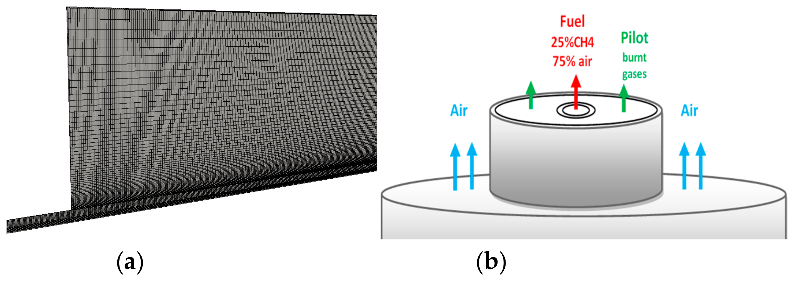
The piloted coaxial methane-air jet flame (Sandia Flame D) [27] is characterized by 3 inlet streams and Re = 22,400. The main jet consists of fuel with a mixture of 25% methane and 75% air by volume. Its inside diameter is dfuel = 0.0072 m and the bulk velocity equal to 49.6 m/s. The pilot jet is composed of lean (phi = 0.77) mixture of C2H2, H2, air, CO2 and N2 with the same nominal enthalpy and equilibrium composition as methane/air at this equivalence ratio. The experimental configuration is represented in Figure 2 where also a 2D computational domain with 32,000 control volumes used is shown. Thereby, the symmetry property of the configuration is exploited in order to save computational costs. The reader is referred to [27] for more details about the experimental set up. Table 1 summarizes the operating conditions in accordance with experiments.
Note that this number of control volumes has been found sufficient to achieve grid-independent solutions. The numerical outflow conditions are imposed at x = 70 d. The outlet plane is set as waveTransmissive condition with P = 101.325 kPa, while all other variables have a zero gradient boundary condition. The time step ∆t used is equal to 1.1 × 10⁻⁶ to ensure CFL-number below one. The convergence of the iterative procedure is assumed if all normalized residuals are smaller than 10−6. The calculations are achieved on 16 to 64 processors depending on the number of stochastic fields used (1 to 128SFi).

3.2. Oxy-Fuel Jet Flame Series

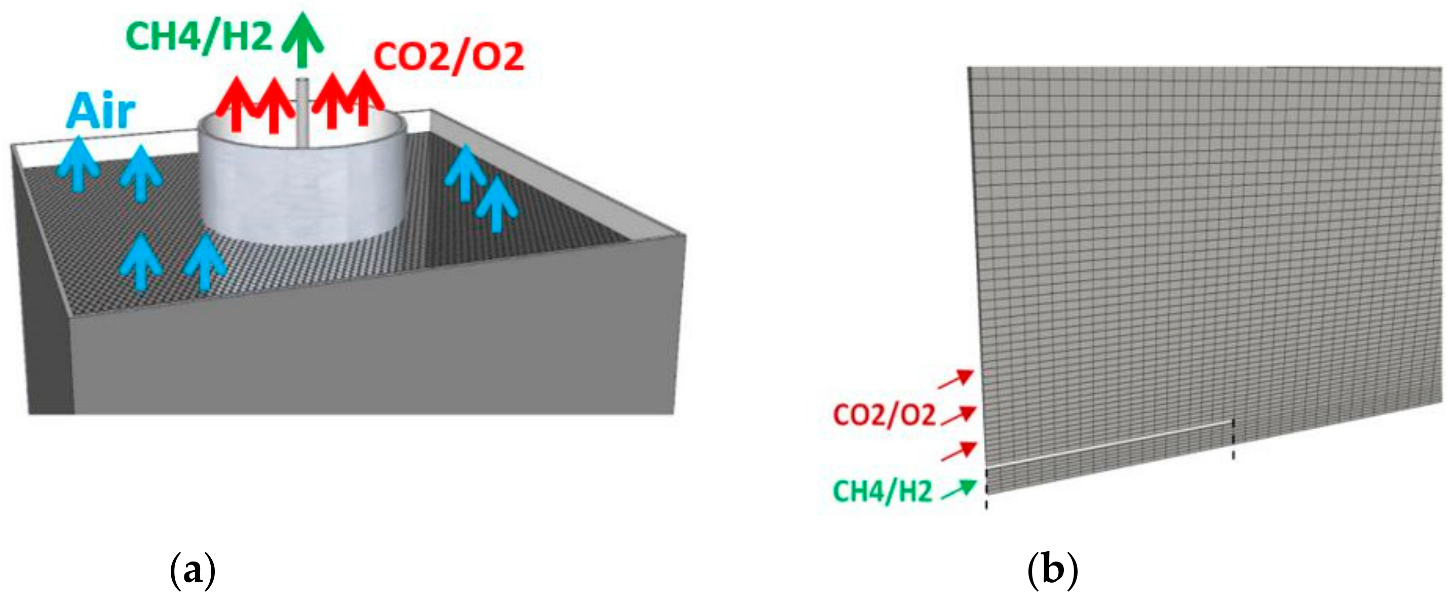
The oxy-fuel jet flame series were investigated experimentally at the Sandia National Laboratories [28]. They consist of two main flame sets, oxy-flames A (1–3) and B (1–3), where the differences between the two series are the Reynolds number and the different compositions of both fuel and oxidizer jets. According to [28], the burner consists of a fuel main jet with inside diameter of 5 mm and 0.5 mm wall thickness. The fuel nozzle is surrounded by a laminar coflow of diameter equal to 96.5 mm. Experimentally the H2 content in the fuel jet helps the flame to remain attached to the nozzle. The fuel jet has its tip 40 mm above the coflow so that the mixed flows are considered fully developed once they reach the tip of the nozzle. Regarding the inlet compositions of the Oxyfuel flame, Table 2 summarizes the different compositions of the fuel for flames A1, A3 and B3 under investigation in the present paper. For the oxidizer stream, a molar percentage of 32% of O2 and 68% of CO2-diluted are used rather than N2. As shown in Figure 3 the two jets are surrounded by a third co-flow which is considered as wind tunnel from where fresh air is flowing in order to accompany the flow of interest and prevent early mixing with ambient air. The third flow is for purely experimental reasons as clearly described in reference [28]. According to [28,50], using the O2/CO2 mixtures instead of air for fuel combustion, the flame temperature can be reduced and NOx emissions are expected to be much lower than in air-diluted conditions. In particular, the composition of the fuel and oxidizer streams generates density fields very different to those found in methane-air flames.
The numerical outflow conditions are imposed at x = 80 d, where the outlet plane is set as waveTransmissive condition with P = 101.325 kPa, while all other variables have a zero gradient boundary condition. The temperature is initially uniformly distributed with 300 K. Taking benefit of the configuration symmetry, for the numerical calculations, a simple 2D computational grid with 28,000 cells, is designed. This was found sufficient for grid independent solutions. The time step ∆t used is equal to 2.1 × 10⁻⁶. Also in these cases, the convergence of the iterative procedure is assumed if all normalized residuals are smaller than 10−6.The number of CPU’s applied to carry out the simulations varies from 16 to 64 depending on the number of SFi employed (varying between 1 and 128SFi).

4. Results and Discussion

4.1. Validation Case: Sandia Flame D

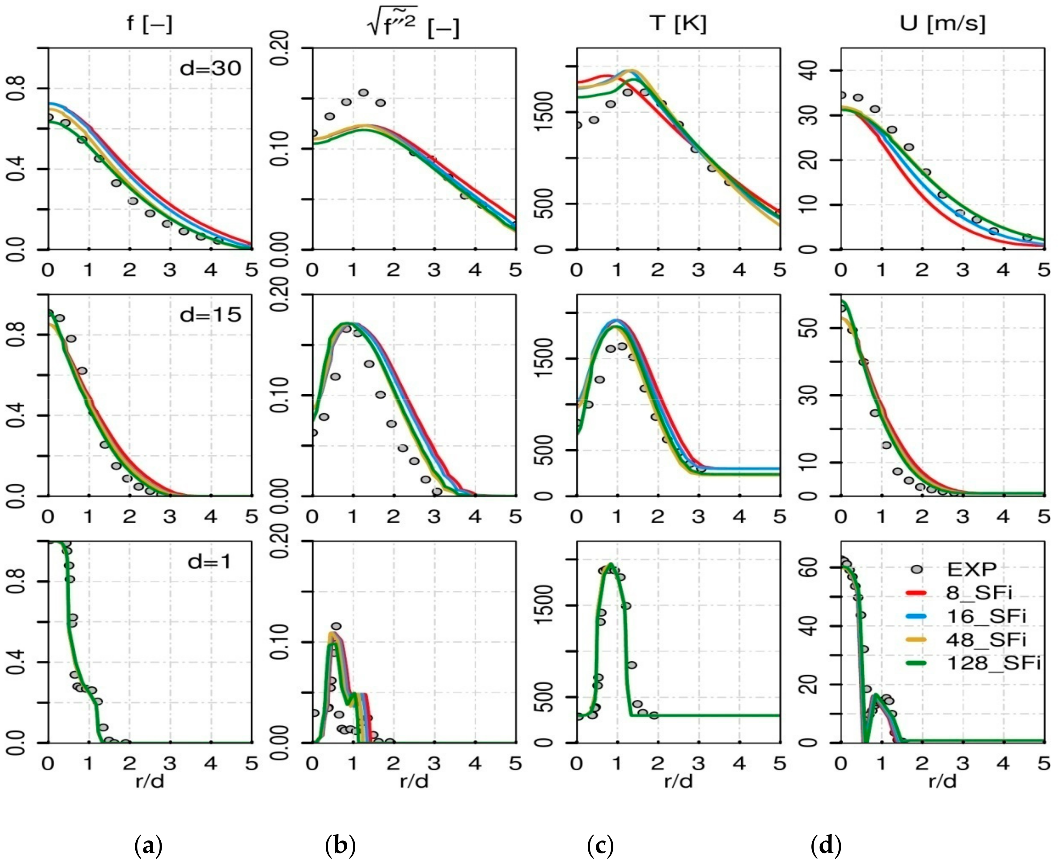
Since this configuration is used to validate the hybrid ESF/FPV approach, the first task was to generate the FPV tables. The FPV tables used are based on non-premixed flamelets and generated according to the procedure in Section 2.2. To examine the convergence of the number of stochastic fields, SFi, the simulations have been done for different numbers of stochastic fields (8, 16, 48 and 128). To assess the combustion/turbulent model, the obtained results are compared to the experimental data in Figure 4 where different radial profiles of mean value of mixture fraction f, the root mean square (rms) of mixture fraction, temperature T and velocity U, are reported at three different axial locations, x = 1 d, 15 d and 30 d.
The results reveal that, close to the fuel/pilot nozzle, the different properties of the flame D using the ESF/FPV approach for all simulations are similar and in a very good agreement with experimental data. However, the influence of increasing the number of stochastic fields can be noticed for the axial profile d = 15, where the results obtained with 128 SFi are closer to the experimental data. At d = 30, the calculations with 128 SFi and 48 SFi lead to results that match better the measurements data. The profiles of mixture fraction rms agree well with experimental data but the values exhibit little deviations. At locations 15 d and 30 d in Figure 4, both the over-prediction of the temperature profiles and the clear under-prediction of the mixture fraction rms could be dueto the RANS turbulent modelling used while considering the 2D computational domain. Similar observations can be made for the mean velocity field in Figure 4d.
Even though the Sandia Flame D is considered as non-complex case, the satisfactory results in Figure 4 qualify the developed hybrid ESF/FPV approach for further investigations.

4.2. Application to a Turbulent OxyfuelJet Flame

4.2.1. Oxyflame B3 and Combustion Modelling Comparison

As pointed out above, three flames A1, A3 and B3 from the oxyflame case series (see Table 2) are considered in order to highlight the effect of O2/CO2 dilution and ofH2% content as well as the impact of the Reynolds number on the flow field and the flame properties using the novel hybrid ESF/FPV approach.
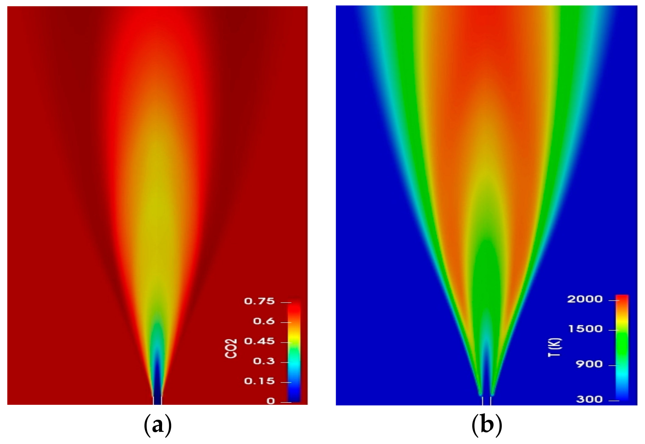
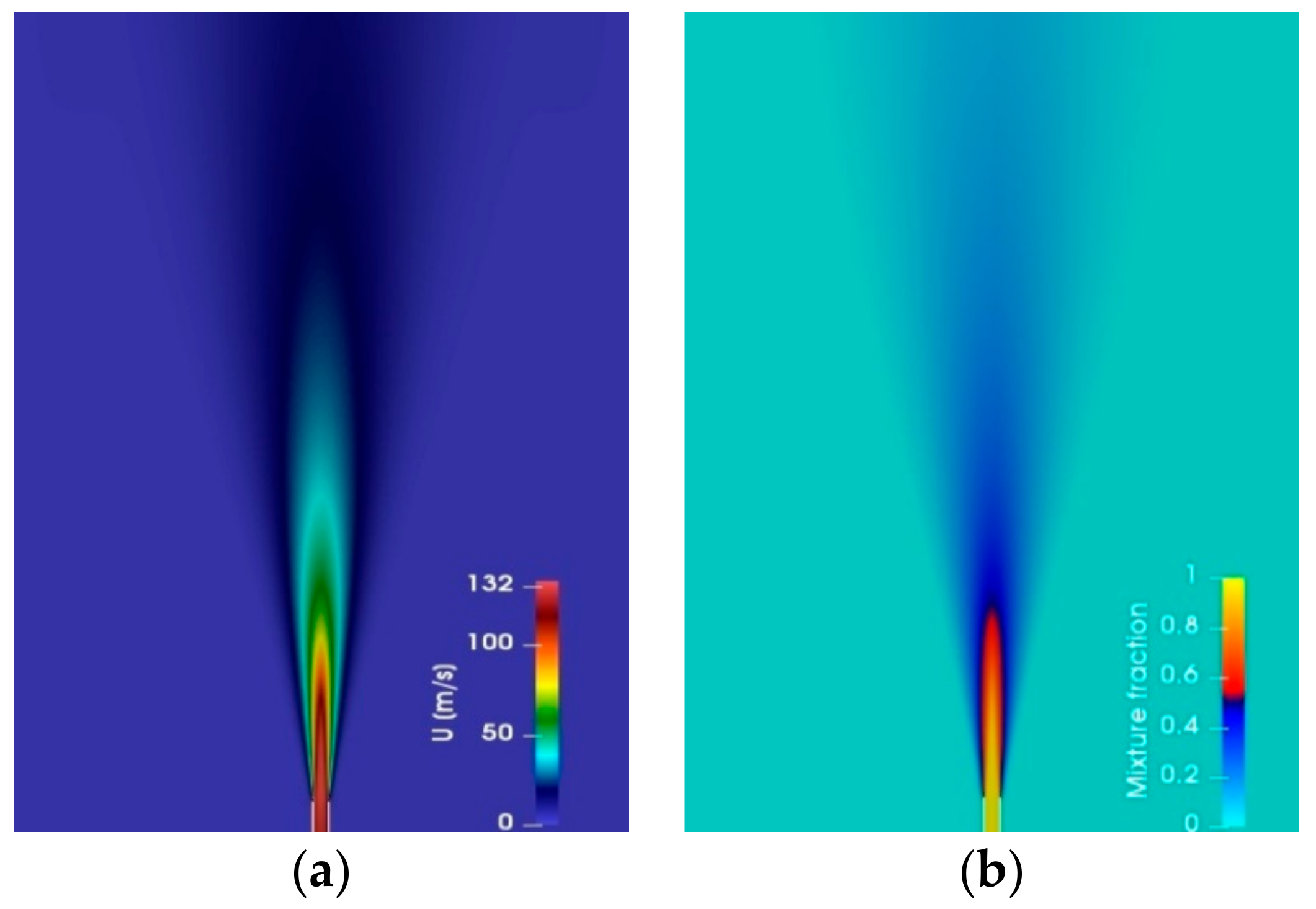
Some of the properties of the oxyflame case B3 are presented in Figure 5 and Figure 6, where both show contour plots of different quantities distribution at mid-plane using the ESF/FPV approach. In Figure 5 both the mean temperature field distribution in (a) and the mean CO2 mass fraction in (b) are smooth and continuous. In Figure 6, the mean mixture fraction distribution and the mean axial velocity profile are displayed. From the contour plots, the flame seems to be attached to the nozzle of the burner by reason of important amount of diluted H2 in the fuel mixture as it is mentioned in the experimental paper [28]. But unfortunately clear experimental qualitative images from the experiments are not available to be compared with the modelled contour-plots in Figure 5 and Figure 6.
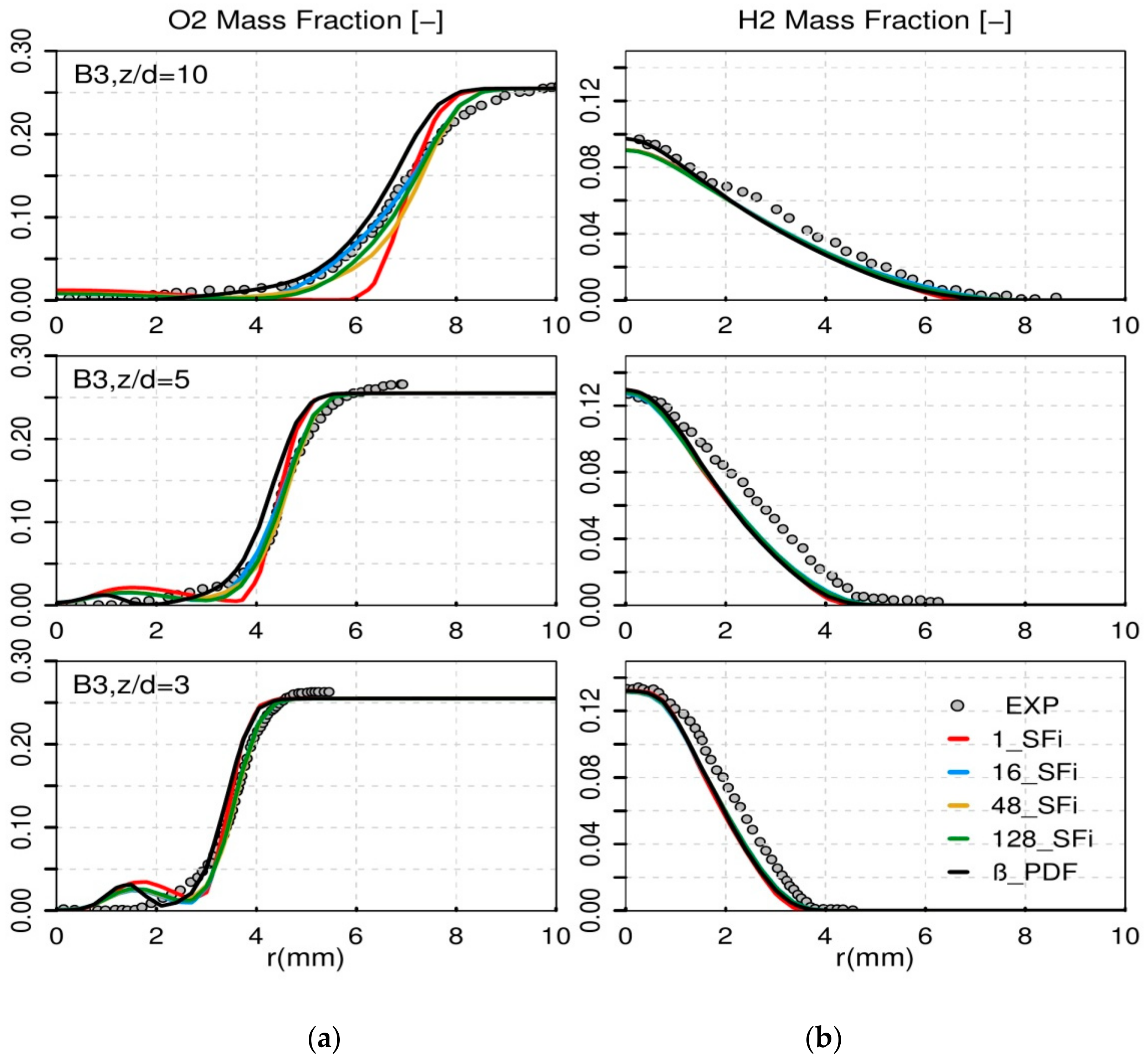
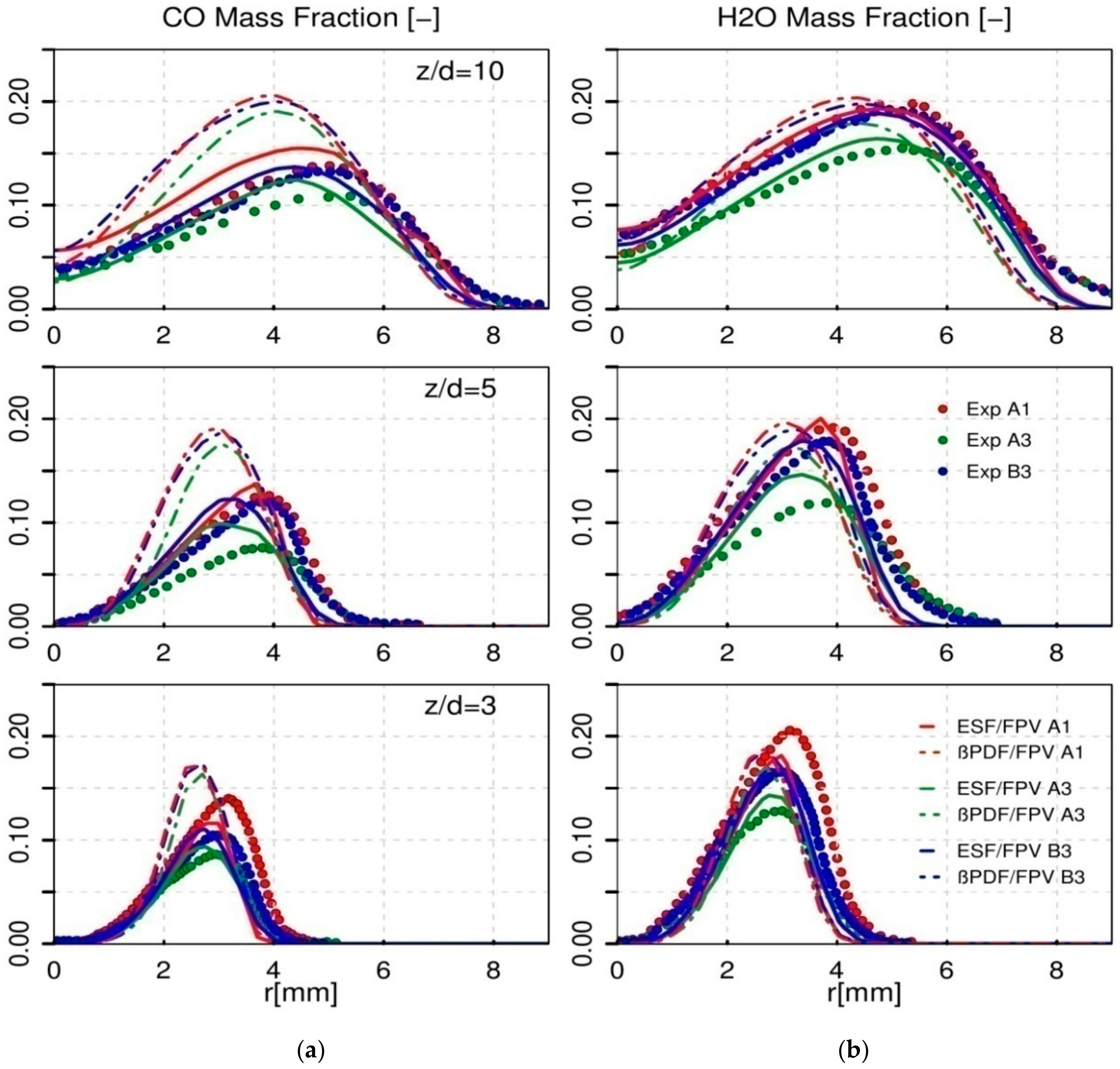
The prediction results of the properties of the flame are then presented by comparing them with the experimental data and with the results obtained by means of the presumed ß-PDF approach. Especially for the hybrid ESF/PFV approach, different number of stochastic fields (SFi = 1, 16, 48, 128) are considered in order to assess the convergence of the ESF. In Figure 7, a comparison of the mean mass fraction of O2 and H2 from the ESF/FPV calculation using different stochastic fields numbers, with experimental data is reported at 3 different axial positions (z/d = 3, z/d = 5 and z/d = 10). For the H2 species, an acceptable agreement is clearly observed between the data at different positions for all SFi numbers. However, for the mean O2 mass fraction prediction, the ESF/FPV calculations using high numbers of SFi are matching the experimental data, whilst there is an under-prediction of O2 mass fraction with 1SFi results at z/d = 5 and z/d = 10. The deviation of the 1SFi results with respect to measurements is also visible in Figure 8 for the prediction of mean mass fraction of CO and H2O going from z/d = 3 to z/d = 10 for both species. These results are expected since using 1SFi means applying simple laminar FPV chemistry without any sub-grid model which is the similar behaviour of a perfectly stirred reactor. Increasing the number of SFi to 16 SFi leads to an under-prediction of both CO and H2O mass fraction at z/d = 10 while the cases using 48 and 128 SFi seem to be in very good agreement with experimental data further from the nozzle. This means that, the use of very high number of stochastic fields in the order of 128 is reproducing closely similar results to the case with 48 stochastic fields. This makes clear that the 48 SFi emerge as acomprise number between better prediction and computational costs. To note is that 128 SFi necessitate 64 CPUs while the 48 SFi only requires 32 CPUs.
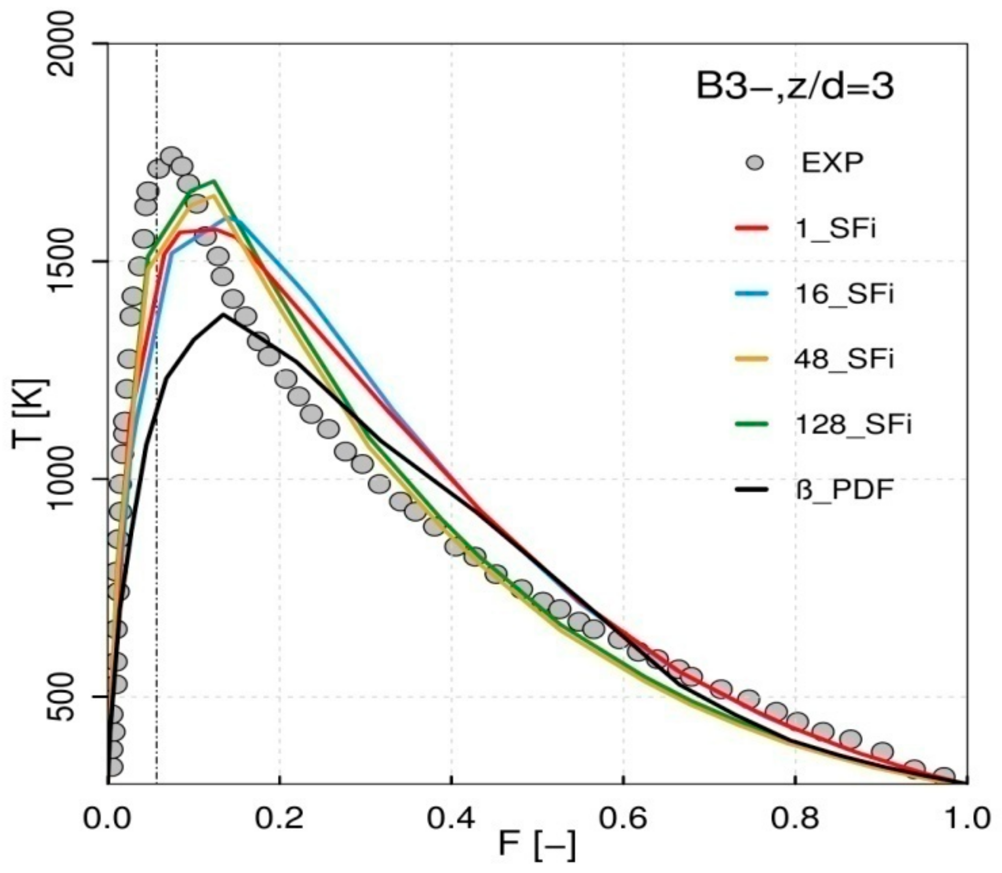
Regarding the calculations using different combustion sub-models, the two different approaches employed, the hybrid ESF/FPV and the presumed ß-PDF, deliver different prediction results for the CO and H2O mass fraction once compared to experimental data. While the hybrid ESF/FPV reproduce closely the reference experimental data of the species, the assumed β-PDF approach suffers from some limitations due to intrinsic assumptions made, like the consideration of statistical independence between single PDF, along with the modelling applied to the source term during its calculation. This prediction failure of the presumed PDF method is also confirmed by the evolution of the mean temperature profile as function of the mixture fraction at z/d = 3 close to the fuel nozzle in Figure 9. In reference [28], the stoichiometric mixture fraction is reported as 0.056 with maximum adiabatic temperature around 1750 K. The hybrid ESF/FPV calculations reproduce a value of 1700 K for both simulations with 48 and 128 SFi. In contrast, the ß-PDF results clearly under-estimate the temperature evolution with a maximum value of 1300K.

4.2.2. H2% Enrichment in Fuel Side

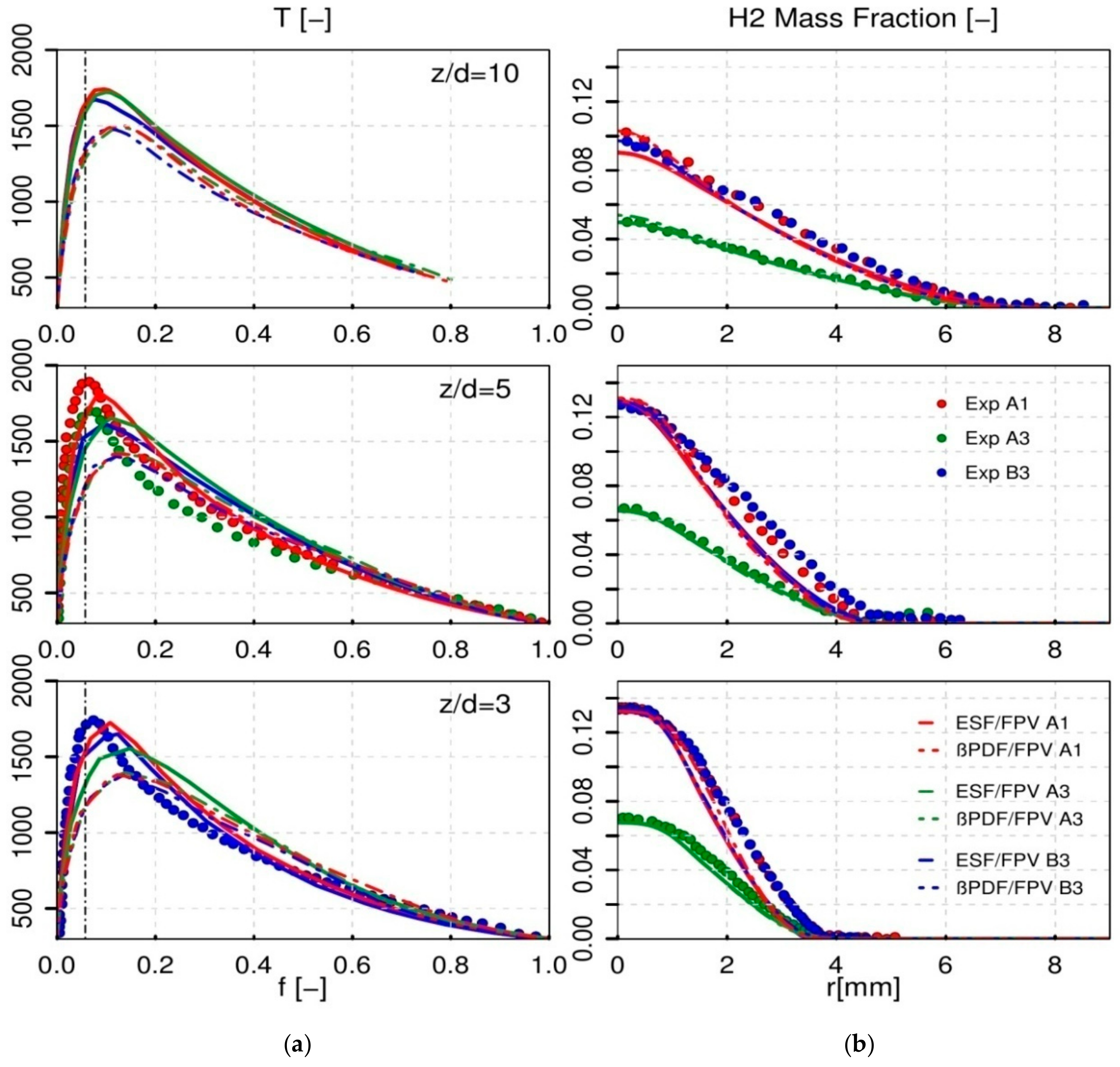
Table 2 shows that, with the same Reynolds number equal to 15,000, the two jet flame cases A1 and A3 feature different percentage of H2% enrichment in the fuel side, with 55% and 37%, respectively. As reported in reference [28], the extinction level increases from flame A1 to A3 and its effect is reported together with the reduction of the mean temperature values around the stoichiometric mixture fraction as reproduced numerically at the axial positions z/d = 3 and z/d = 5 in Figure 10.
Although the increase in temperature with H2% enrichment is observed close to the nozzle from A1 to A3, this temperature difference disappears at positions far from the nozzle at z/d = 10 where the numerical prediction of the temperature profile of both flames leads to similar results. Unfortunately, experimental results of temperature at further positions, z/d     10, are not available as can be seen in Figure 10. Not only is the temperature’s peak value changing while reducing the H2% enrichment in the fuel for flame A3 at z/d = 3 but also the shifting of the maximum adiabatic temperature from stoichiometry toward rich side is visible. Further, Figure 11 presents the radial profiles of mean mass fraction of both CO and H2O.
For the flame A1 with the highest CH4/H2 ratio, both CO and H2O productions are higher than in flame A3 at different axial positions in accordance with experimental findings. This is of interest despite that the Lewis number effect has not been included at the present stage of the FPV combustion model assuming Le = 1.

4.2.3. CO2 Dilution in Oxidizer Side

The CO2 amount diluted within the oxidizer is constant in flames A and B series and is about 68% which is quite a high level. This results in the high level of production of CO and H2O as it can be seen in Figure 11. For flame cases A1 and B3 which include both the same H2% enrichment in fuel side and same CO2 dilution, the CO mass fraction locally reaches at z/d = 5 an amount of 0.14 and increases at z/d = 10 to reach 0.16 which is not a regular value for cases with air-diluted flames. This confirms previous finding by Masri et al in reference [51] who presumed that the CO2 diluted in oxidizer is not inert and CO high level formation is the result of the reaction of CO2 with H to form CO species. Therefore, the CO production level in flames A1 and B3 is manifestly higher than in A3 at all positions. Only the results with the hybrid ESF/FPV could reproduce this trend except for H2. Furthermore, the temperature is slightly reduced once compared to the air/methane flame.

4.2.4. Reynolds Number Effect

Both jet flame cases A1 and B3 share the same CH4/H2 ratio in the fuel side but are characterized by different Reynolds numbers. From Figure 10, one can observe that the maximum adiabatic temperature location toward the mixture fraction space remains nearly the same for both flames at 3 and 10 diameters above the nozzle. However in Figure 11, there is a clear augmentation in the production of mean mass fraction of both CO and H2O species at the axial position z/d = 3 for flame A1 with lower Re-number. The difference of CO and H2O formation is reduced far from the nozzle. It turns out that the mixing state near the nozzle with lower jet Reynolds number likely leads to higher CO formation level. It turns out, that only the hybrid ESF/FPV is able to reproduce satisfactorily this trend.

5. Conclusions

Numerical investigations of an oxy-fuel non-premixed jet flame, with high CO2 diluted level in the oxidizer and different CH4/H2 ratios, have been carried out using a novel hybrid Eulerian Stochastic Field (ESF)/Flamelet Progress Variable (FPV) combustion model within the RANS modelling framework. After a successful validation of the combustion model in the piloted CH4/Air jet flame, the combustion behaviour of an oxyfuel jet configuration featuring the flame series A1, A3 and B3 has been studied. These flames exhibit different CH4/H2 and O2/CO2 ratios in the fuel and oxidizer streams, respectively and are characterized by different Reynolds numbers. This study allowed for tracing the impact of these properties on the temperature profiles and the CO and H2O formation. The obtained results were compared to available experimental data and to achievements accomplished by using a presumed β-PDF combustion model. Following important conclusions can be drawn down:
  • A good prediction of different experimental and flow field variables, is reported by using the novel ESF/FPV approach.
  • Related to the convergence of the stochastic field number (SFi), it turned out that starting the calculations with 48 SFi emerged as the compromise between accurate prediction and computational costs.
  • Comparing the two different PDF-based combustion models, it turned out that the hybrid ESF/FPV clearly showed superiority in better predicting the temperature, H2O mass fraction and specially CO mass fraction, unlike the presumed β-PDF model which under-estimates the maximum adiabatic temperature and over-predicts the CO formation level at different positions above the nozzle downstream.
  • With lower H2% enrichment in fuel side, fixed CO2/O2 ratio and constant Reynolds number, the maximum adiabatic temperature value decreases in a significant manner near the fuel nozzle and its location in the mixture fraction space is shifted toward the reach side of the fuel.
  • With lower Reynolds number, constant CO2/O2 and CH4/H2 ratios, the CO formation is considerably intensified near the nozzle.
Despite encouraging results provided by the hybrid ESF/FPV approach, it is still important to consider the H2 differential diffusion effect which may affect the prediction of other minor species. The results reported in the present paper may suffer from the limitations of the RANS turbulence model used. The task of coupling the hybrid ESF/FPV approach with Large Eddy Simulation technique for more accurate prediction of the turbulence, along with the turbulence-chemistry interaction, is left for future research work.

Author Contributions

Conceptualization, R.M. and A.S.; Methodology, R.M., M.J. and A.S.; β-PDF solver, M.P.; T-PDF solver, M.J.; Hybrid-ESF/FPV solver development, R.M., M.J. and A.S.; Settings up, R.M.; Simulations and Validation, R.M. Formal Analysis, R.M., M.P. and AS.; Investigation, R.M.; Resources, A.S. and B.F.; Data Curation, R.M., M.J. and M.P.; Writing-Original Draft Preparation, R.M.; Writing-Review & Editing, A.S., M.J.,M.P. and B.F.; Visualization, A.S. and M.J.; Supervision, A.S. and B.F.; Project Administration, A.S.

Funding

This project was funded by the European Union’s Horizon 2020 under the Marie Sklodowska-Curie grant agreement 643134 (CLEAN-Gas).

Acknowledgments

The authors of this work gratefully acknowledge the financial support by the European Union’s Horizon 2020 research and innovation program [CLEAN-Gas] with grant number 643134, also the financial support by the DFG (German Research Council) CRC/Transregio 150 “Turbulent, chemically reactive, multi-phase flows near walls” All the numerical simulations were carried out on the Hessen High Performance Computer (HHLR) at the Technical University of Darmstadt.

Conflicts of Interest

The authors declare no conflict of interest.

Nomenclature

C f Model constant for mixture fraction variance
C ε 1 Model constant in dissipation rate equation
C ε 2 Model constant in dissipation rate equation
C μ Model constant
C Φ Micro-mixing model coefficient
dW Wiener term
fMixture fraction
F Joint probability density function
G k Production of turbulence kinetic energy
K Turbulent kinetic energy
N Number of stochastic field
N α Number of the chemical table controlling variables
p Pressure
P Probability density function
Re Reynolds number
S ij Strain rate tensor
t Time
T Temperature
U i Velocity component in ith direction
W Molar mass
x i Positions coordinate in ith direction
Y Mass fraction
Δ t Time increment
δ ij Kronecker-symbol
ρ Density
μ Dynamic molecular viscosity
μ t Dynamic turbulent viscosity
σ Schmidt number
σ t Turbulent Schmidt number
σ k Model constant
σ ε Model constant
ε Dissipation rate of turbulent kinetic energy
ω ˙ Chemical source term
Φ General species variable
δ Dirac delta function
ψ Composition space of species
α Referring to table controlling variable
ξ α n nth stochastic field of the variable α
( . ) ˜ Favre weighted quantity
( . ) ¯ Mean quantity
T-PDFTransported probability density function
ESFEulerian Stochastic Field
PVProgress Variable
FPVFlamelet Progress Variable
P-PDFPresumed probability density function
SDEStochastic differential equations
RANSReynolds averaged Navier–Stokes
CCSCarbon Capture and Storage
FGMFlamelet Generated Manifold
CMCConditional Moment Closure

References

  1. Energy Agency. Available online: https://www.iea.org/newsroom/news/2015 (accessed on 1 October 2018).
  2. Zheng, L. Oxy-Fuel Combustion for Power Generation and Carbon Dioxide (CO2) Capture; Woodhead Publishing series in energy; Elsevier: Cambridge, UK, 2011. [Google Scholar]
  3. Jangi, M.; Li, C. Modelling of Methanol Combustion in a Direct Injection Compression Ignition Engine using an Accelerated Stochastic Fields Method. Energy Procedia 2017, 105, 1326–1331. [Google Scholar] [CrossRef]
  4. Hidouri, A.; Chrigui, M.; Boushaki, T.; Sadiki, A.; Janicka, J. Large eddy simulation of two isothermal and reacting turbulent separated oxy-fuel jets. Fuel 2017, 192, 108–120. [Google Scholar] [CrossRef]
  5. Pierce, C.D.; Moin, P. Progress-variable approach for large-eddy simulation of non-premixed turbulent combustion. J. Fluid Mech. 2004, 504, 73–97. [Google Scholar] [CrossRef]
  6. Ihme, M.; Pitsch, H. Prediction of extinction and reignition in non-premixed turbulent flames using a flamelet/progress variable model 2. Application in LES of Sandia flames D. and E. Combust. Flame 2008, 155, 90–107. [Google Scholar] [CrossRef]
  7. Jordi, V.M. Numerical Simulation of Turbulent Diffusion Flames Using Flamelet Models on Unstructured Meshes. Ph.D.Thesis, Centre Tecnologic de Transferencia de Calor Departament de Maquinesi Motors Termics Universitat Politecnica de Catalunya, Terrassa, Spain, 2015. [Google Scholar]
  8. Ferraris, S.A.; Wen, J.X. LES of the Sandia Flame D Using Laminar Flamelet Decomposition for Conditional Source-Term Estimation. Flow Turbul. Combust. 2008, 81, 609–639. [Google Scholar] [CrossRef]
  9. Di Renzo, M. LES of the Sandia Flame D Using an FPV Combustion Model. Energy Procedia 2015, 82, 402–409. [Google Scholar] [CrossRef]
  10. Hunger, F.; Zulkifli, M.; Williams, B.; Beyrau, F.; Hasse, C. A combined experimental and numerical study of laminar and turbulent non-piloted Oxyfuel jet flames using a direct comparison of the Rayleigh signal. FlowTurbul. Combust. 2016, 97, 231–262. [Google Scholar] [CrossRef]
  11. Shahbazian, N.; Groth, C.P.T.; Gülder, O. Assessment of Presumed PDF Models for Large Eddy Simulation of Turbulent Premixed Flames. In Proceedings of the 49th AIAA Aerospace Sciences Meeting including the New Horizons Forum and Aerospace Exposition, Orlando, FL, USA, 4–7 January 2011. [Google Scholar]
  12. Raman, V.; Pitsch, H. Eulerian transported probability density function sub-filter model for LES simulations of turbulent combustion. Combust. Theory Model. 2007, 10, 439–458. [Google Scholar] [CrossRef]
  13. Jones, W.P.; Prasad, V.N. Large Eddy Simulation of the Sandia Flame Series (D–F) using the Eulerian stochastic field method. Combust. Flame 2010, 157, 1621–1636. [Google Scholar] [CrossRef] [Green Version]
  14. Pope, S.B. PDF methods for turbulent reactive flows. Prog. Energy Combust. 1985, 11, 119–192. [Google Scholar] [CrossRef]
  15. Pope, S.B. A Monte Carlo Method for the PDF Equations of Turbulent Reactive Flow. J. Combust. Sci. Technol. 2008, 25, 159–174. [Google Scholar] [CrossRef]
  16. Valińo, L. A field Monte Carlo formulation for calculating the probability density functions of a single scalar in turbulent flow. Flow Turbul. Combust. 1998, 60, 157–172. [Google Scholar] [CrossRef]
  17. Haworth, D.C. Progress in the probability density function methods for turbulent reacting flows. Prog. Energy Combust. Sci. 2010, 36, 168–259. [Google Scholar] [CrossRef]
  18. Fox, R.O.; Raman, V. A multienvironment conditional probability density function model for turbulent reacting flows. Phys. Fluids 2004, 16, 4551–4565. [Google Scholar] [CrossRef]
  19. Sabelnikov, V.; Soulard, O. Rapidally decorrelating velocity-field model as tool for solving one-point Fokker-Planck equations for probability density functions of turbulent reactive scalars. Phys. Rev. 2005, 72. [Google Scholar] [CrossRef]
  20. Jones, W.P.; Marquis, A.; Prasad, V. LES of a turbulent premixed swirl burner using the Eulerian stochastic field method. Combst. Flame 2012, 159, 3079–3095. [Google Scholar] [CrossRef]
  21. Jones, W.P.; Navarro-Martinez, S. Numerical study of n-heptane auto-ignition using LES-PDF methods. Flow Turbul. Combust. 2009, 83, 407–423. [Google Scholar] [CrossRef]
  22. Jangi, M.; Lucchini, T.; Gong, C.; Bai, X.S. Effects of fuel cetane number on the structure of diesel spray combustion: An accelerated Eulerian stochastic fields method. Combust. Theory Model. 2015, 19, 549–567. [Google Scholar] [CrossRef] [Green Version]
  23. Gong, C.; Jangi, M.; Bai, X.S.; Liang, H.; Sun, M.B. Large eddy simulation of hydrogen combustion in supersonic flows using an Eulerian stochastic fields method. Int. J. Hydrogen Energy 2017, 42, 1264–1275. [Google Scholar] [CrossRef]
  24. Gong, C.; Jangi, M.; Bai, X.S. Diesel flame lift-off stabilization in the presence of laser-ignition: A numerical study. Combust. Theory Model. 2015, 19, 696–713. [Google Scholar] [CrossRef]
  25. Avdic, A.; Kuenne, G. DiMare, F.; Janicka, J. LES combustion modelling using the Eulerian stochastic field method coupled with tabulated chemistry. Combust. Flame 2017, 175, 201–219. [Google Scholar] [CrossRef]
  26. El-Asrag, H.A.; Graham, G. A comparison between two different Flamelet reduced order manifolds for non-premixed turbulent flames. Available online: https://www.google.com.tw/url?sa=t&rct=j&q=&esrc=s&source=web&cd=1&cad=rja&uact=8&ved=2ahUKEwjq9sa639DeAhUT97wKHeSeBGIQ7gEwAHoECAkQBw&url=https%3A%2F%2Ftranslate.google.com.tw%2Ftranslate%3Fhl%3Dzh-TW%26sl%3Den%26u%3Dhttps%3A%2F%2Fsutherland.che.utah.edu%2FUSCI2013%2FPAPERS%2F2E01-070LT-0182.pdf%26prev%3Dsearch&usg=AOvVaw2U7BugwRgM4neQCdg1UIsV (accessed on 1 October 2018).
  27. TNF Workshop. Available online: http://www.ca.sandia.gov/TNF (accessed on 1 October 2018).
  28. Sevault, A.; Dunn, M.; Barlow, R.S.; Ditaranto, M. On the Structure of the Near Field of Oxy-Fuel Jet Flames Using Raman/Rayleigh Laser Diagnostics. Conbust. Flame 2012, 159, 3342–3352. [Google Scholar] [CrossRef]
  29. Ditaranto, M.; Hals, J. Combustion instabilities in sudden expansion oxy–fuel flames. Combust. Flame 2006, 146, 493–512. [Google Scholar] [CrossRef]
  30. Coppens, F.H.V.; Konnov, A.A. The effects of enrichment by H2 on propagation speeds in adiabatic flat and cellular premixed flames of CH4 + O2 + CO2. Fuel 2008, 81, 2866–2870. [Google Scholar] [CrossRef]
  31. Garmory, A.; Mastorakos, E. Numerical simulation of oxy-fuel jet flames using unstructured LES-CMC. Proceed. Combust. Ins. 2014, 35, 1207–1214. [Google Scholar] [CrossRef] [Green Version]
  32. Launder, B.E.; Sharma, B.I. Application of the Energy-Dissipation Model of Turbulence to the Calculation of Flow Near a Spinning Disc. Lett. Heat Mass Trans. 1974, 1, 131–138. [Google Scholar] [CrossRef]
  33. Branley, N.; Jones, W.P. Large eddy simulation of a turbulent non-premixed flame. Combust. Flame 2001, 127, 1914–1934. [Google Scholar] [CrossRef]
  34. Cook, A.W.; Riley, J.J.; Kosály, G. A laminar flamelet approach to subgrid-scale chemistry in turbulent flows. Combus. Flame 1997, 109, 332–341. [Google Scholar] [CrossRef]
  35. De Bruyn Kops, S.M.; Riley, J.J. Direct numerical simulation of laboratory experiments in isotropic turbulence. Phys. Fluids 1998, 10, 2125–2127. [Google Scholar] [CrossRef]
  36. Kempf, A.; Sadiki, A.; Janicka, J. Prediction of finite chemistry effects using large eddy simulation. Proceed. Combust. Ins. 2003, 29, 1979–1985. [Google Scholar] [CrossRef]
  37. Bekdemir, C.; Somers, L.; Angelberger, C. Predicting diesel combustion characteristics with Large-Eddy simulations including tabulated chemical kinetics. Proceed. Combust. Ins. 2013, 34, 3067–3074. [Google Scholar] [CrossRef]
  38. Wehrfritz, W.; Kaario, O.; Vuorinen, V.; Somers, L. Large Eddy Simulation of ndodecane spray flames using Flamelet generated manifolds, combustion and flame. Combust. Flame 2016, 167, 113–131. [Google Scholar] [CrossRef]
  39. FlameMaster v3.3.10. Available online: https://web.stanford.edu/group/pitsch/FlameMaster.htm (accessed on 1 October 2018).
  40. Gri-Mesh3.0. Available online: http://www.me.berkeley.edu/gri_mech/ (accessed on 1 October 2018).
  41. Subramaniam, S.; Pope, S. A mixing model for turbulent reactive flows based on Euclidean minimum spanning trees. Combst. Flame 1998, 115, 487–517. [Google Scholar] [CrossRef]
  42. Gao, F.; O’Brien, E.E. A large eddy simulation scheme for turbulent reacting flows. Phys. Fluids 1993, 5, 1282–2184. [Google Scholar] [CrossRef]
  43. Jaberi, F.A.; Colucci, P.J. Large eddy simulation for heat and mass transport in turbulent flows. Part 2: Scalar field. Int. J. Heat Mass Trans. 2003, 46, 1827–1840. [Google Scholar] [CrossRef]
  44. Jaberi, F.A.; Colucci, P.J.; James, S.; Givi, P.; Pope, S. Filtered mass density functionfor Large eddy simulation of turbulent reacting flows. J. Fluid Mechan. 1999, 401, 85–121. [Google Scholar] [CrossRef]
  45. Dopazo, C. Probability density function approach for a turbulent axisymmetric heated jet. Centerline evolution. Phys. Fluids 1975, 18, 397–404. [Google Scholar] [CrossRef]
  46. Gardiner, C.W. Handbook of Stochastic Methods:For Physics, Chemistry and the Natural Science, 2nd ed.; Springer: Berlin/Heidelberg, Germany, 1985. [Google Scholar]
  47. Landenfeld, T.; Sadiki, S.; Janicka, J. A turbulence-chemistry interaction model based on multivariable presumed Beta-PDF methods for turbulent flames. Flow Turbul. Combust. 2002, 68, 111–135. [Google Scholar] [CrossRef]
  48. Keeheon, I.Y. Investigation of the Scalar Variance and Scalar Dissipation Rate in URANS and LES. Ph.D.Thesis, University of Waterloo, Waterloo, ON, Canada, 2011. [Google Scholar]
  49. Greenshields, C.J. OpenFOAM Programmer’s Guide. Available online: http://foam.sourceforge.net/docs/Guides-a4/OpenFOAMUserGuide-A4.pdf (accessed on 1 October 2018).
  50. Ditaranto, M.; Sautet, J.C.; Samaniego, J.M. Structural aspects of coaxial oxy-fuel flames. Exp. Fluids 2001, 30, 253–261. [Google Scholar] [CrossRef]
  51. Masri, A.R.; Dibble, R.W.; Barlow, R.S. Chemical kinetic effects in non-premixed flames of H2/CO2 fuel. Combust. Flame 1992, 91, 285–309. [Google Scholar] [CrossRef]
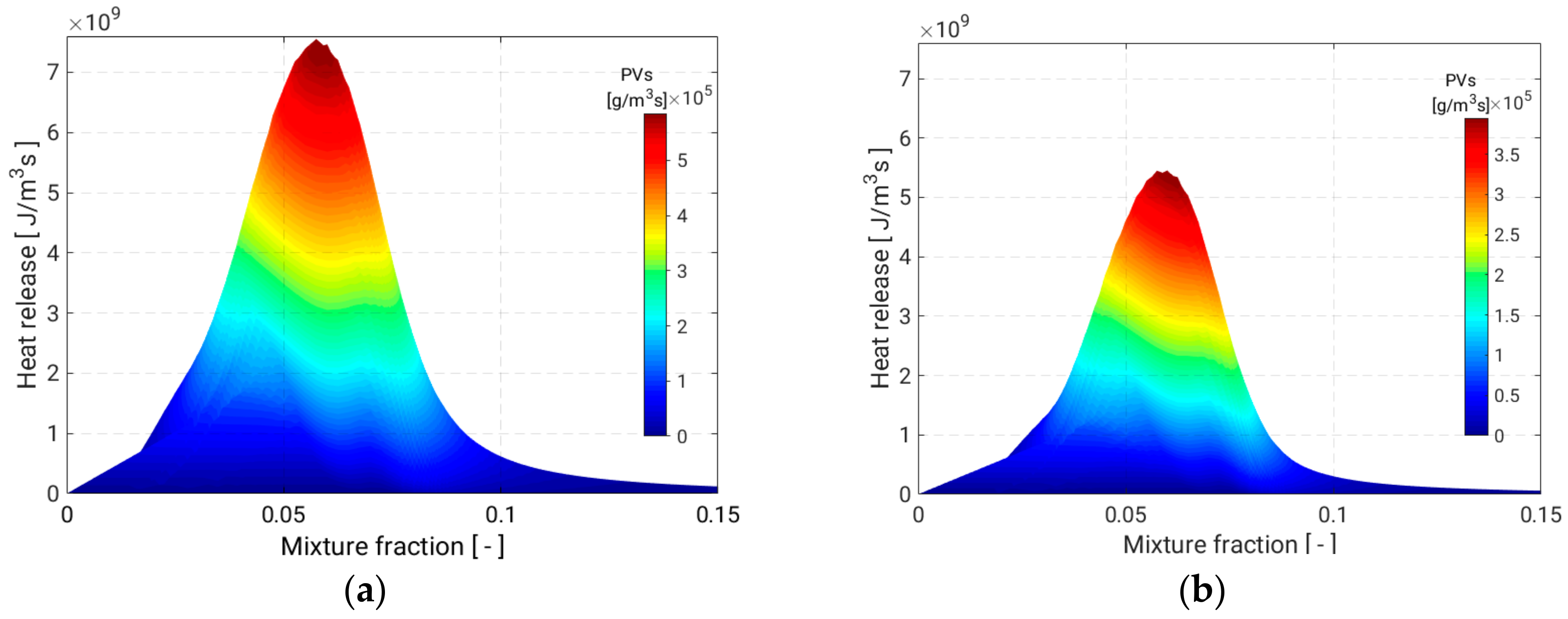
Figure 1. Production rate of heat release in the mixture fraction space coloured with source term of the PV. (a) distribution of heat release in Flames A1, B3 tables, (b) distribution of heat release in Flame A3 table.
Energies 11 03158 g001
Figure 2. Sandia Flame-D configuration, (a) Description of the piloted CH4/Air jet FlameD (b) A 2D numerical block structured Grid.
Energies 11 03158 g002
Figure 3. Oxyfuel configuration (a) Description of the Oxyfuel configuration according to the experimental set up in reference [28]. (b) Inlets part from the 2D numerical block structured grid.
Energies 11 03158 g003
Figure 4. Comparison between experimental data for Flame-D [16] and RANS numerical results for different numbers of SFi at different axial positions; d = 1, d = 15 and d = 30, (a) mean mixture fraction, (b) rms of mixture fraction, (c) mean temperature and (d) mean velocity.
Energies 11 03158 g004
Figure 5. Contour plots from ESF/FPV simulation for Oxyfuelflame B3: (a)Temperature distribution, (b) meanCO2 mass fraction.
Energies 11 03158 g005
Figure 6. Contour plots from ESF/FPV simulation for Oxyfuel flame B3: (a) mean velocity, (b) mixture fraction.
Energies 11 03158 g006
Figure 7. Mean O2 (a) and H2 (b) mass fraction from ESF/FPV simulation for different SFi at different axial positions in comparison with Raman/Rayleigh data of B3 from [28].
Energies 11 03158 g007
Figure 8. Mean CO (a) and H2O (b) mass fraction from ESF/FPV simulation for different SFi at different axial positions in comparison with Raman/Rayleigh data of B3 from [28].
Energies 11 03158 g008
Figure 9. Mean Temperature from ESF/FPV simulation for different SFi at axial position z/d = 3 in comparison with Raman/Rayleigh data of B3 from [28].
Energies 11 03158 g009
Figure 10. Mean temperature profile in mixture fraction space (a) and H2 mass fraction (b) results from ESF/FPV simulation with 48 SFi at different axial positions for flame cases A1, A3 and B3 in comparison with β-PDF results and Raman/Rayleigh data from [28].
Energies 11 03158 g010
Figure 11. Mean CO (a) and H2O (b) mass fraction from ESF/FPV simulation with 48 SFi at different axial positions for flame cases A1, A3 and B3 in comparison with β-PDF results and Raman/Rayleigh data from [28].
Energies 11 03158 g011
Table 1. Description of the initial/boundary numerical conditions for piloted jet Flame-Sandia-D.
ParameterFuelPilotCo-FlowUnits
Mixture fraction0.1560.0430---
Progress variable070---
T2941880291K
Velocity49.611.40.9m/s
ν1.513 × 10⁻⁵m2/s
Reynolds Number22,000---
Table 2. Description of the initial/boundary numerical conditions for Oxyfuel Flames.
Flame%H2 in FuelRefuelVel. Fuel
[m/s]
Vel. Oxy
[m/s]
PVOxyν
[m2/s]
A15515,00084.40.77503.271 × 10−5
A33715,00075.80.73903.271 × 10−5
B35518,000117.80.93303.271 × 10−5