1. Introduction
Airborne wind energy (AWE) is a promising technology to overcome the technical and the economic constraints of conventional wind turbines for harnessing the stronger and more consistent winds present at higher altitudes. This technology utilises a tethered free-flying kite or glider or flying turbine (in some design approaches) to reach altitudes unreachable for conventional wind turbines. It eliminates the requirement for civil structures such as towers to elevate the system into the wind. Since the first patent of airborne wind energy by Van Gries in 1938 [
1], several types of AWE systems have been invented and introduced by researchers and engineers in different universities and companies [
1,
2,
3,
4]. The non-reversing pumping-mode AWE system employing a kite or a glider for harnessing the wind energy is the focus of this paper [
5]. Non-reversing pumping mode AWE systems have been initially developed at the University of Limerick, Ireland [
5,
6,
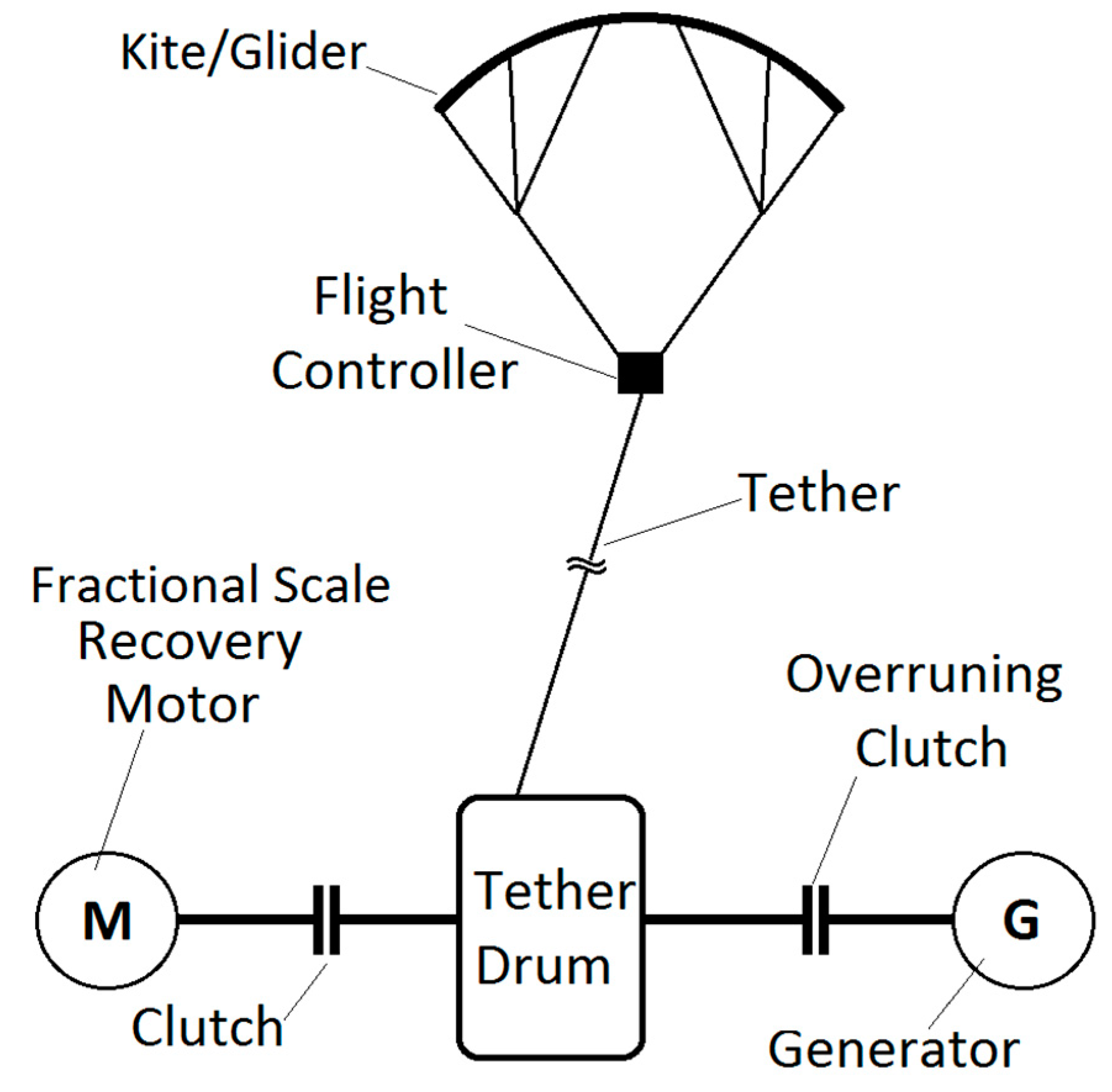
7]. In this type of pumping mode AWE system, a kite or glider is tethered to a ground station consisting of a tether drum coupled to a generator and a fractional scale recovery motor. The operation cycle is divided into two phases, a power phase and a recovery phase. During the power phase, the generator is mechanically connected to the tether drum and generates electrical power from the tension profile provided by the flying wing. At the maximum tether length, the operation must be switched to the recovery phase. During the recovery phase, the generator is mechanically bypassed by an overrunning clutch, and the tether drum is reversed by the recovery motor to recover the tether to its initial length [
5]. Use of a separate fractional scale motor for the recovery process is the principal deference of the non-reversing pumping mode AWE systems compared to the conventional pumping mode AWE devices where they reverse the generator for use as a motor for the recovery process. Reversing the generator in the conventional pumping mode procedure creates difficulty for utility-scale grid interconnection due to the inefficiencies of stopping a large generator and reversing the system as a motor [
5]. A variation on the concept of using a separate motor and generator for the recovery phase and power phase are considered by the researchers at TU Delft [
8]. The non-reversing pumping mode AWE system is illustrated in
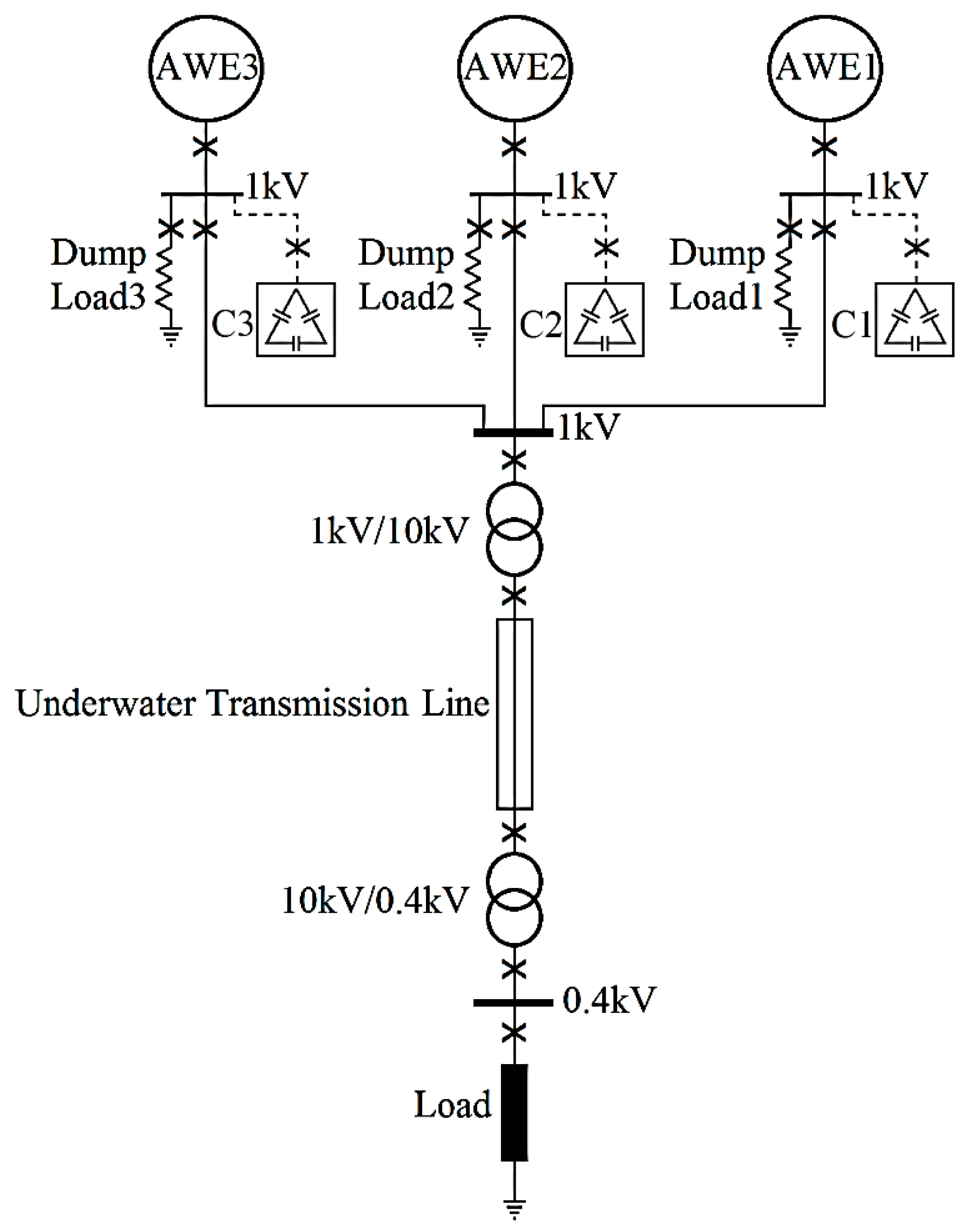
Figure 1 (see [
5] for greater detail).
Compared to the conventional wind turbines, the need for less mechanical and civil construction has made AWE systems an ideal technology for floating offshore wind energy systems where the size of offshore construction is significantly critical [
8,
9,
10]. A factor which is more important when reported studies show increasing attention to the offshore wind resources due to higher wind energy availability, less environmental effects and less land limitation in comparison with on-land wind energy systems [
11,
12]. For instance, the potential of Ireland for the installation of offshore and on-land wind energy systems by 2050 is 30 GW and 11–16 GW, respectively [
13], almost double the capacity for offshore wind compared to on-land wind. Furthermore, the Irish maritime area is ten times larger than the country’s landmass providing an exceptional land area for the installation of floating wind energy systems [
14].
The direct interconnection technique is a new approach to improve the cost and availability of offshore wind energy systems. Pican et al. first introduced the direct interconnection technique (DIT) in 2011 for conventional offshore wind turbines [
15,
16]. In this technique, unlike the conventional approach, all the offshore units are directly interconnected to each other without any power electronic converter. After dispatching the generated power to shore, the farm power is converted in compliance with grid codes by a back to back converter or several paralleled back to back converters. Given that the power electronic converters possess a high rate of failure among the wind turbine sub-assemblies [
17,
18] and given high expenses of off-shore operations for offshore located back to back converters, this method could provide a significant improvement in the economy and the reliability of the offshore airborne wind energy systems. The direct interconnection technique and the conventional approach for off-shore power integration are illustrated in
Figure 2. The first DIT implementation attempt for AWE systems is reported in [
5]. In [
5], a DIT algorithm is implemented on an offshore AWE farm simulation model proving the initial feasibility of this technique for pumping mode AWE system. The research work of [
5] is followed by [
19] to investigate the performance of the directly interconnected AWEs under normal and fault conditions. However, there remain many questions about the efficiency and power control of the directly interconnected AWE systems that this current paper answers.
This paper aims to evaluate and optimise the power control of the directly interconnected non-reversing pumping mode AWE systems. Considering AWE systems are directly interconnected to the main bus of the energy farm without any power electronic converter, the power control of the internal grid is an important question as it is a highly dominant factor on the efficiency and performance of the AWE energy farm. In this regard, this research focuses on the power control of the directly interconnected AWE generators inside the internal power grid of an energy farm. Three non-reversing pumping mode AWE systems are modelled and simulated as a minimum viable offshore energy farm. The AWE generators are directly interconnected to the main bus of the energy farm in accordance with the proposed algorithm and by use of automatic frequency and synchronisation controllers. The interaction of the directly interconnected AWE systems inside the internal power grid is studied. Active power, reactive power, power factor, voltage sag and total harmonic distortion (THD) are measured and analysed for the internal power grid of the AWE energy farm. A reactive power compensator (RPC) is designed and implemented to improve the reactive power exchange inside the energy farm internal grid. Also, a load sharing controller (LSC) controls the active power and load balance. Comparing the power generated by the directly interconnected non-reversing pumping mode AWE systems before and after adding the LSC and RPC shows significant improvements in voltage and current oscillation reduction, load balance, and reduction in reactive power of the internal power grid.
3. Simulation Results
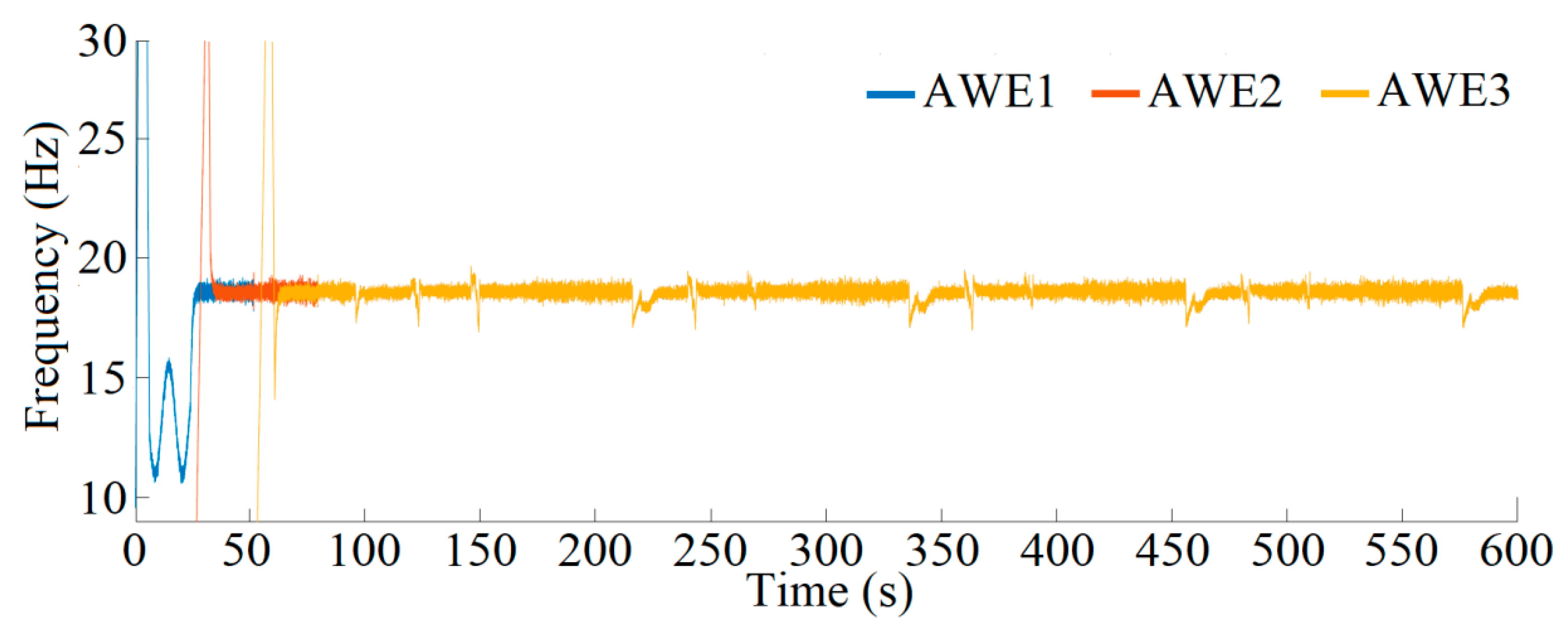
The frequency of the generators for 600 s is demonstrated in
Figure 6. AWE1 starts to work at t = 0, and AWE2 and AWE3 launch the operation with 26 s delay at t = 26 s and t = 52 s, respectively. With the operation of each generation unit, automatic frequency controller and automatic synchronisation controller are activated to prepare the corresponding system for the main bus interconnection. As can be seen in
Figure 6, AWE2 is integrated into the main bus at t = 51.69 s, and AWE3 joins the main bus at t = 79.45 s. Since the incoming torque from the wing is highly oscillatory, it is not possible to achieve a constant frequency. However, the AFCs can control the steady state frequency within a reasonable range (less than 5% error) around the operational frequency. After interconnecting all generation units to the main bus, the generators are synchronised, and one AFC can control the main bus frequency. Hence, AFC1 is considered as the main bus frequency controller, and if AFC1 is in the recovery phase or faulty, AFC2 operates as the backup main bus controller.
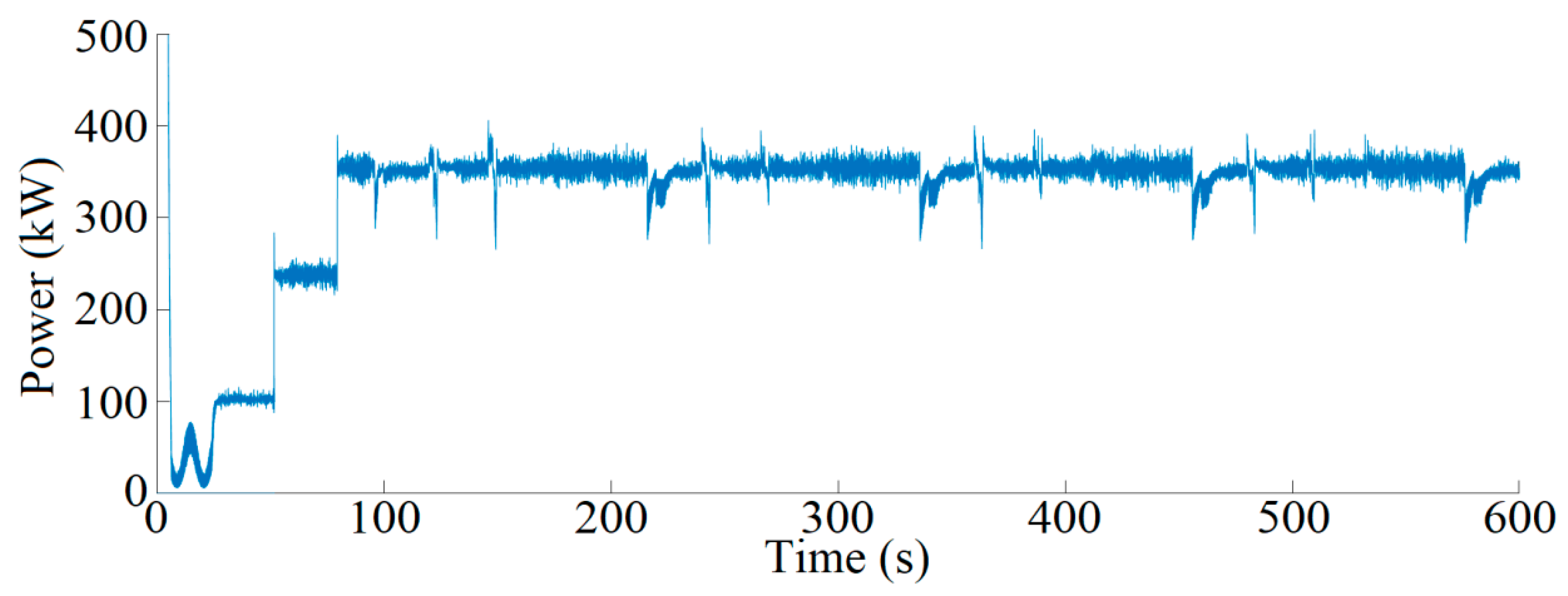
The generated power at the main bus is demonstrated in
Figure 7. At the start, only AWE1 is interconnected with the main bus and generates 105 kW electrical power. After the interconnection of AWE2 and AWE3, the electrical power at the main bus increases to 235 kW and 350 kW respectively. However, the power generated by each generator is discontinuous. The total power at the main bus is continuous due to the applied time delay between the operation of the AWE systems. Due to the fluctuations in incoming torque from the wing, the active power at the main bus is highly oscillatory. Hence, the utilisation of a power electronic converter before interconnection to the load or the grid is proposed as necessary. According to
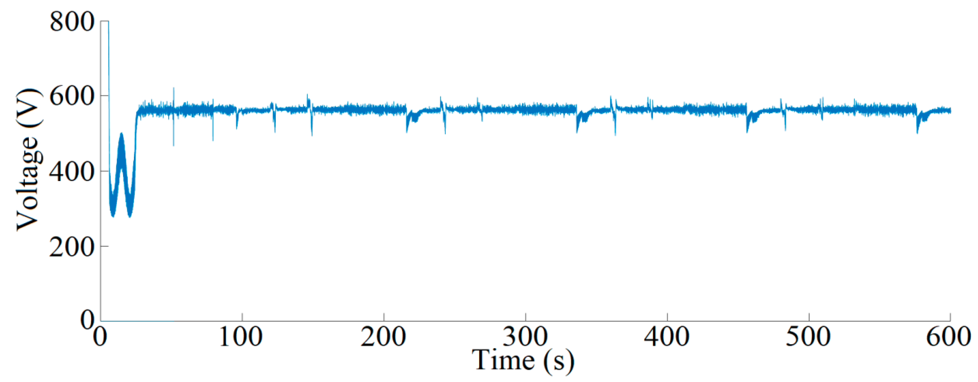
Figure 8, the RMS value of the phase voltage at the main bus is 564 V, and the peak value of the main bus voltage is 810 V.
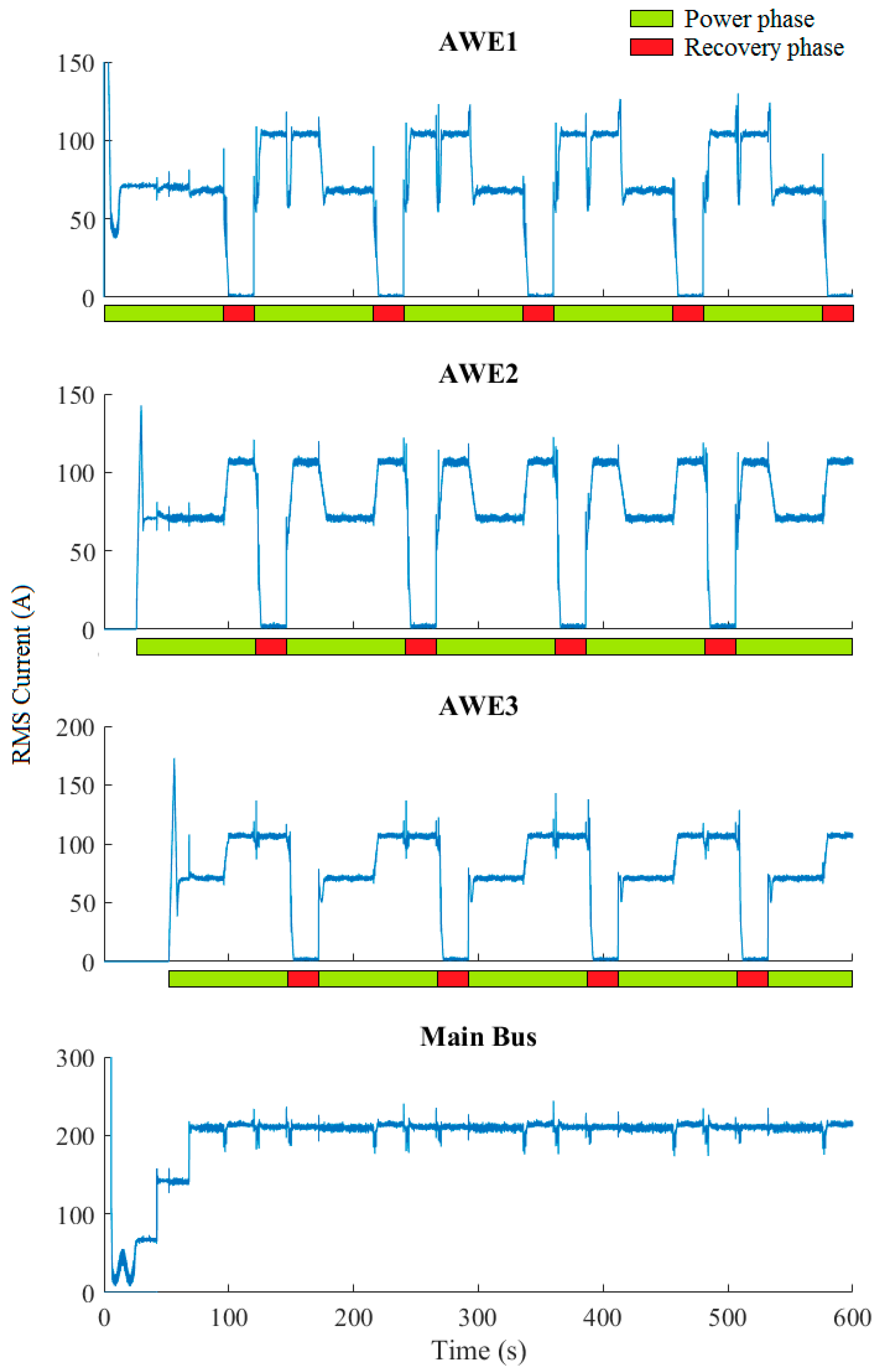
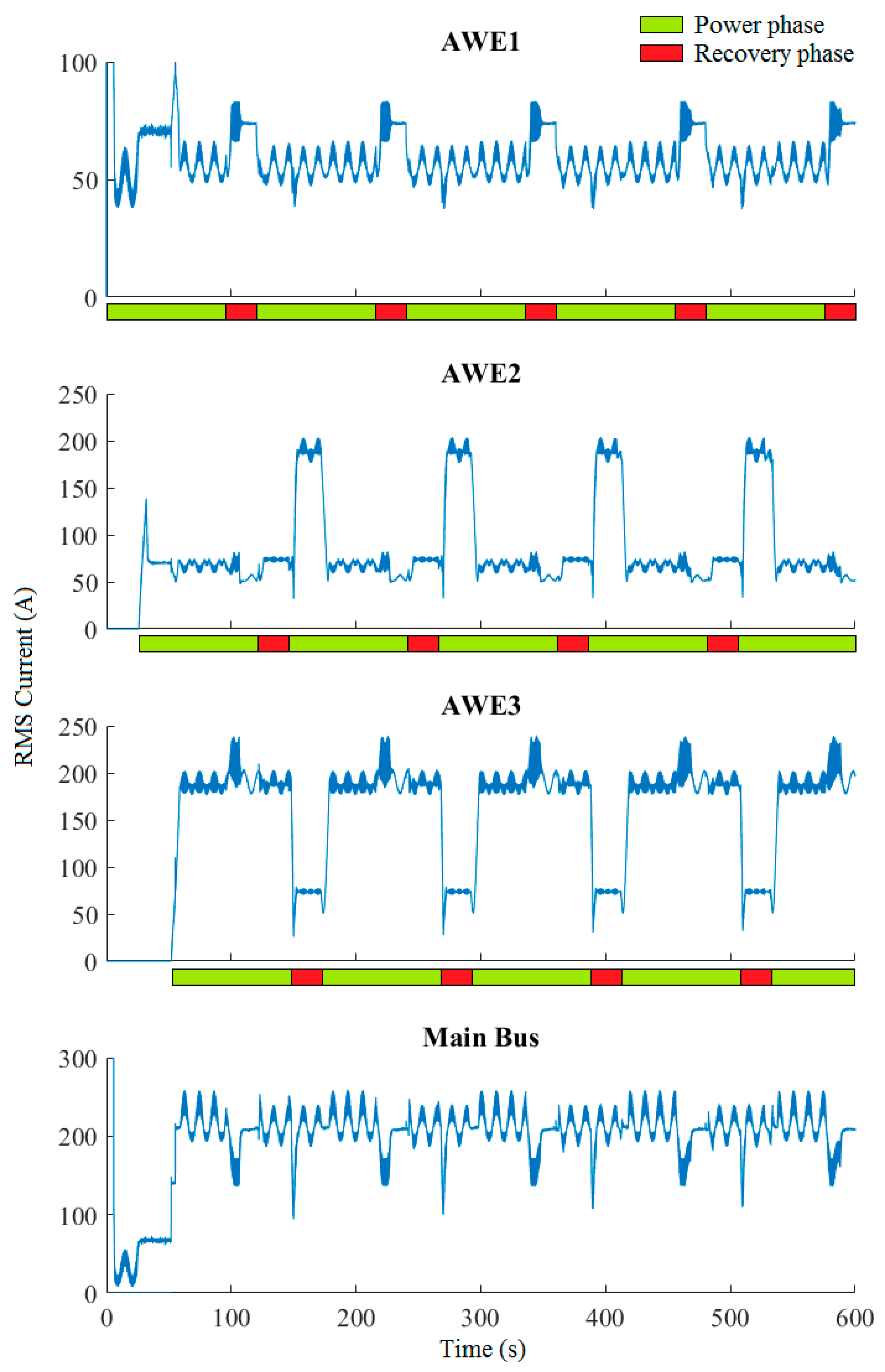
Figure 9 shows the measured root-mean-square (RMS) current at the terminals of the generators and the main bus. As can be seen, after the interconnection of all generators to the main bus, total current at the main bus changes between 210 A to 260 A. In
Figure 9, the power phase and the recovery phases of the operation are highlighted by green and red colours, respectively.
When a directly interconnected AWE unit operates in the recovery phase, it stops power generation and operates as an unloaded synchronous motor. This condition leads to the increase of power generation by other generators to compensate the power shortage, so that power in the main bus is continuous. However, the increase in the power generation is not equal. For instance, between t = 96 s and t = 120 s when AWE1 is in the recovery phase, AWE2 and AWE3 change their generated current to around 59 A and 200 A, respectively. Improper power flow and uneven contribution in the generated current can be harmful to the farm power system by increasing the risk of a pole-slipping fault [
24,
25,
26] and increasing the power losses and current inconsistency due to the circulating current between the generators [
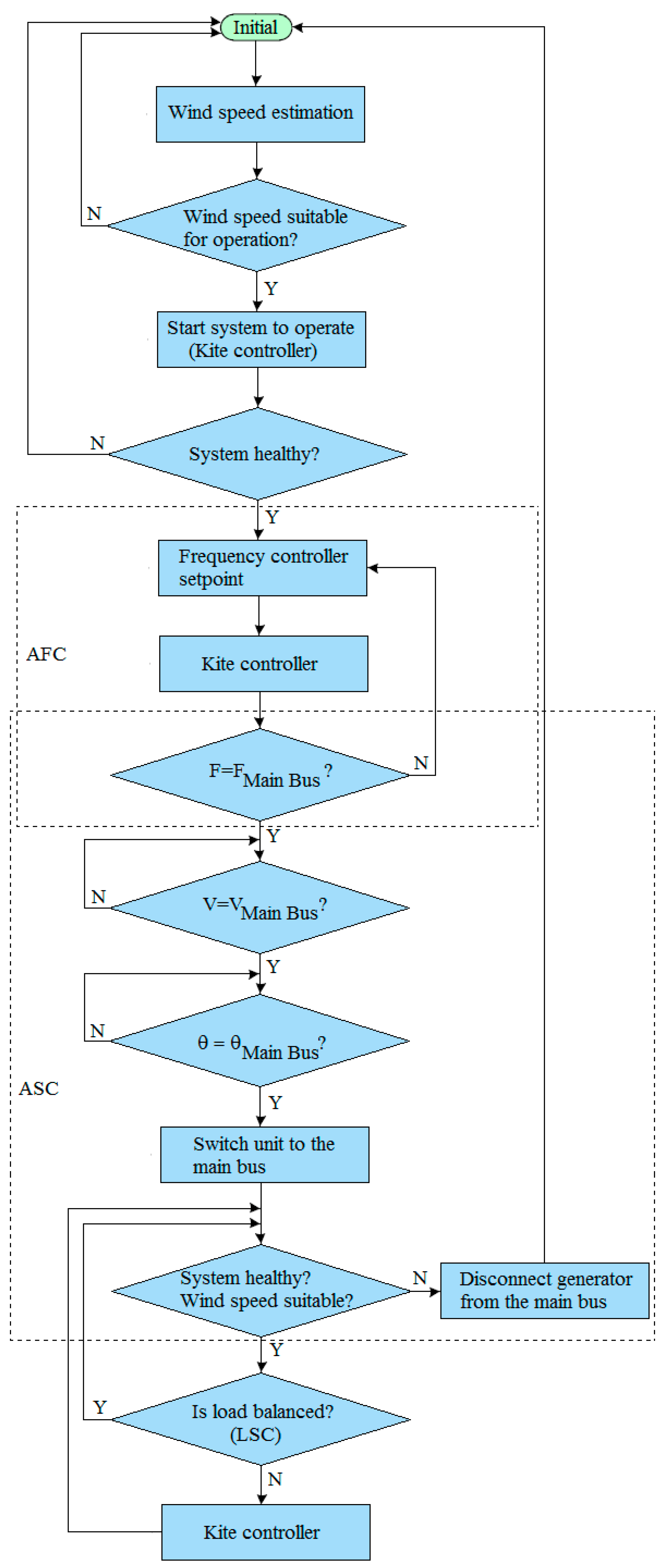
27]. A load sharing controller (LSC) is designed and developed to maintain the load balance in the farm power network. The control diagram of the farm is illustrated in
Figure 10. The LSC measures and compares the current at the main bus and the generated current by each interconnected generator. If the LSC recognises that a generator is loaded more than other generators it tries to correct the generator contribution by regulating the mechanical torque applied to the generator. The LSC consists of three proportional controllers (P-controllers). Each P-controller controls the power contribution of one AWE unit. Considering the load and the number of power phase and recovery phase AWEs, the LSC estimates each unit’s share to set the reference values of P-controllers.
The mechanical torque regulation can be performed by sending a command signal to the kite controller which alters the trajectory and aerodynamic properties of the wing.
Figure 11 demonstrates the generators and the bus currents after adding the LSC. As can be seen, the load is divided equally between the generators. For instance, between t = 96 s and 120 s when AWE1 is in the recovery phase, the generated currents by AWE2 and AWE3 increase evenly to 110 A. As mentioned, after interconnection of all generators to the main bus, AFC1 operates as the pilot controller to control the farm frequency. In the load sharing strategy, AWE1 is the only generation unit which is permitted to generate slightly more than other generators for the frequency regulation. Comparing
Figure 9 and
Figure 11 shows the implementation of the LSC causes a significant reduction in the main bus current fluctuations.
In
Figure 9 and
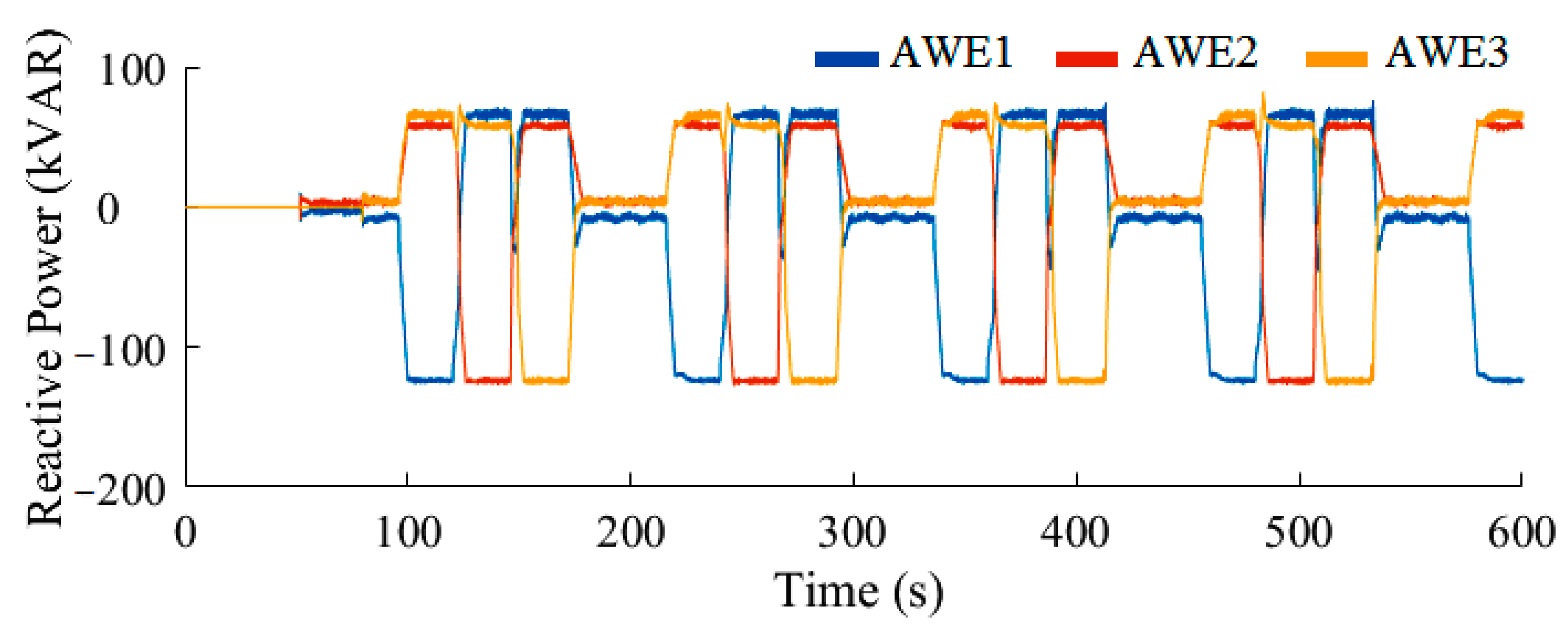
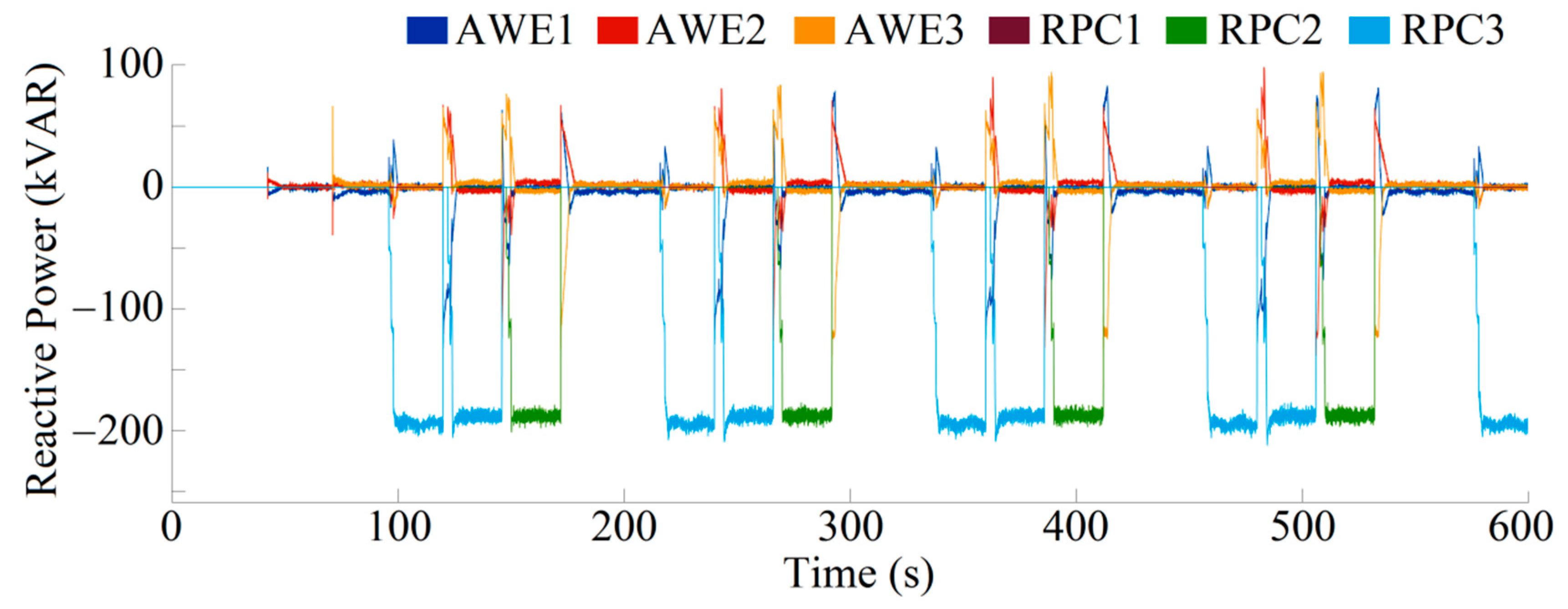
Figure 11, it can be observed that when a directly interconnected AWE unit is in the recovery phase, the PMSG exchanges about 74 A current with the main bus of the internal power grid. This circulation is due to the reactive power exchange between the idling recovery phase generator and the other generators. To elaborate, during the recovery phase the generator is mechanically decoupled from the kite and the tether drum, but it remains electrically connected to the main bus. In this condition, the permanent magnet synchronous generator operates as an unloaded synchronous motor. This unloaded synchronous motor draws a small amount of active power and exchanges a significant amount of reactive power to stay synchronised with the other generators. The reactive power exchange can be seen in
Figure 12. As an illustration, between t = 96 s and t = 120 s, AWE1 is in the recovery phase, and it exchanges 125 kVAR leading reactive power with the main bus. During the same time, it can be seen that the reactive powers of AWE2 and AWE3 are increased to 62 kVAR and 63 kVAR lagging, respectively. This reactive power exchange between the recovery phase AWE and the power phase AWEs reduces the power factor of the generators. Also, it results in increased power losses by increasing the current flow through the internal power grid equipment such as transmission lines, generators, transformers and circuit breakers. A reactive power controller (RPC) is developed and implemented for each AWE unit. The RPC consists of a variable capacitor bank parallel to the terminals of the generator, and a controller tracking the reactive power exchanges. If an RPC detects any lagging reactive power at the output of an AWE unit, it switches the appropriate number of capacitors to the generator terminal to compensate the lagging reactive power. In
Figure 3, the capacitor banks are specified by C1, C2, and C3 for AWE1, AWE2, and AWE3 respectively. After adding RPC to each AWE unit, the reactive power exchange is limited to the synchronous machine and the shunt capacitor banks connected to the machine terminals, and it is not exchanged between the AWE units through the farm internal power grid anymore.
Figure 13 demonstrates the reactive power exchange inside the energy farm internal power grid after adding the RPCs. As can be seen, when an AWE unit is in the recovery phase, the amount of exchanged reactive power with other generators is decreased by 95%. For instance, when AWE1 is in the recovery phase (between t = 96 and 120) the exchanged reactive power with the AWE2 and AWE3 (except during the transient time of the phase transmission) is 6.5 kVAR approximately. During this period, the lagging reactive power is compensated by RPC2 and RPC3. Similarly, when AWE2 and AWE3 operate in the recovery phase, the lagging reactive power is compensated by RPC1 and RPC3 for the AWE2 recovery phase, and RPC1 and RPC2 for the AWE3 recovery phase, and the circulating reactive power is decreased significantly. This reactive power compensation can improve the capacity of the AWE energy farm for providing more active power to the load/grid by reducing the circulating current inside the internal power grid.
Figure 14 shows the farm currents after the utilisation of RPCs. Compared to
Figure 11, the current exchange of the recovery phase AWE with the main bus has decreased from 74 A to 3.5 A, which is a 95.27% reduction in the circulating current.
Table 2 compares the average power factors of the AWE units before and after the use of RPCs. In this table, “+” indicates a lagging power factor, and “−” represents a leading power factor. A significant improvement in the power factor can be seen by adding RPCs to the farm. For instance, without RPC, the average power factor of the AWE1 during the recovery phase is 0.01 leading while, by RPC, it is corrected to 0.83 lagging. The power factor improvement can be observed for AWE2 and AWE3 as well. The average power factor of AWE2 and AWE3 over the recovery phase is improved from the weak value of 0.01 leading to 0.70 and 0.72 lagging, respectively. Additionally, the average power factor of the power phase AWEs when one AWE unit operates in the recovery phase is improved to the value of 1.
Figure 15 shows a voltage sag investigation at the main bus of the energy farm. According to the IEEE 1159 standard, voltage sag is a voltage drop to between 10 to 90% of the nominal voltage lasting more than half of a cycle and less than one minute [
28]. Voltage sag can happen as a result of events such as short circuit fault, the start of induction motors and variations in the load [
28]. This type of voltage drop can be a critical problem since it can affect the proper operation of the power system causing damage to the power grid and end-user equipment [
28]. Furthermore, it may lead to unwanted protection system trips [
28]. In DIT, the transition of an interconnected generator from the power to recovery phase and vice versa cases, variations in the mechanical torque and speed of the tethered wing, and the switching operation of the capacitor banks (after adding RPCs) can potentially cause voltage sag in the energy farm power network. The represented voltage sag analysis in
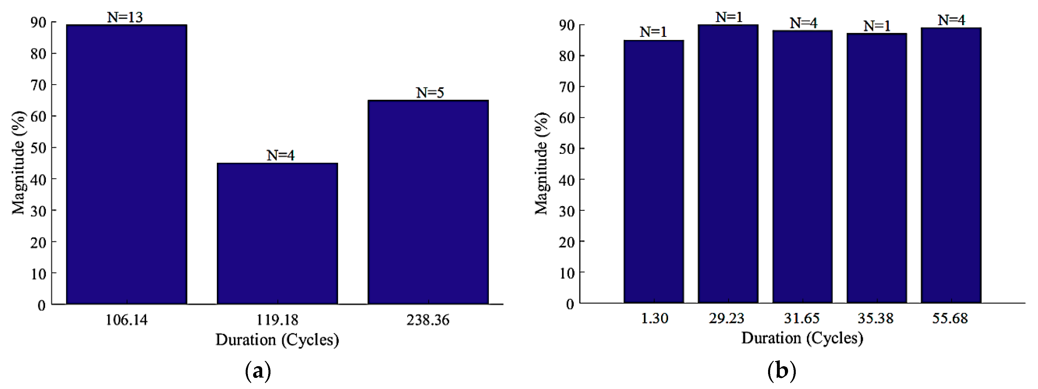
Figure 15 compares voltage sag events with and without the LSC and RPC for 600 s of the simulation at the main bus of the internal power grid. In this figure, the term ‘N’ represents how many times each voltage sag event has happened.
Figure 15a shows that without the LSC and RPCs, a total of 22 voltage sag events have occurred. Among them, the most intensive is the sag to 45% with the duration of 119.18 cycles and a repetition of four times. The longest voltage sag is 238.36 cycles with a magnitude of 65% and repetition five times. The sag to 89% is the most frequent voltage sag event with 13 repetitions and duration of 106.14 cycles.
Figure 15b represents voltage sag analysis after adding the LSC and RPCs. The number of voltage sag events is reduced to 11; a 50% improvement in the number of voltage sag events. In
Figure 15b the most intensive event is a sag to 85% with a duration of 1.30 cycles, compared to the most intensive sag before adding LSC and RPCs (
Figure 15a) 88.88% and 98.90% improvement in the magnitude and duration is achieved, respectively. Additionally,
Figure 15b shows that the longest sag with LSC and RPCs is 55.68 cycles while without the LSC and RPCs it was 238.36 cycles, i.e., a 76.64% improvement.
Figure 16 investigates the total harmonic distortion (
THD) of the main bus current before and after implementation of the LSC and RPCs.
THD is an index showing the signal distortion due to harmonics. Current
THD can be determined by Equation (1) as the ratio of the cumulative harmonics to the fundamental frequency of the current [
29].
where
Ii is the RMS value of
i-th order harmonic and
I1 is the RMS value of the fundamental frequency of the current.
In
Figure 16a it can be observed that without the implementation of the LSC and RPCs the main bus current
THD can rise to 65.3%.
Figure 16b shows the maximum current
THD is decreased to 27.94% by the use of LSC and RPCs which is a 57.21% decrease in current
THD at the main bus. This significant improvement in the
THD of the power generated by the directly interconnected generators is highly effective in the reduction of core losses in power transformers and electrical machines lowering the thermal stress on the farm internal power grid equipment [
30]. However, this
THD is still unsuitable for electric power consumers as according to the IEEE Std. 519-1992 the current
THD at the point of common coupling (PCC) with the infinite power grid must be below 5% [
30]. Hence,
THD must be reduced to less than 5% for the grid interconnection by the implementation of one or several paralleled back to back power electronic converters in the onshore substation before integration with the infinite power grid. As mentioned, such converters are, in any case, required for frequency and voltage compliance.
4. Discussion and Conclusions
The direct interconnection technique is a novel approach for the integration of offshore airborne wind energy systems. In this technique, transferring the power electronic converters from the offshore site to shore can significantly improve the economy and reliability of the offshore AWE farms. However, this paper shows that the elimination of the power electronic converters from the terminals of the generators and the integration of AWE generators directly to the offshore main bus can lead to less controllability and, hence, reduced power factor, significant reactive power exchange between the generators, poor load balance, and wild fluctuations in voltage and current. Accordingly, a DIT internal power grid needs power controllers to improve the efficiency and reliability of generated power. It is shown that without controlling the contribution of each generator in the active power generation, the load is divided unequally between the generators. This uneven load sharing loads some generators more than other generators and can be harmful to the overloaded generators and the internal power grid equipment, such as transformers, breakers, and capacitors.
The reactive power exchange between the directly interconnected airborne wind energy systems has been analysed. It is shown that when an AWE unit operates in the recovery phase, it exchanges a considerable amount of reactive power with other interconnected machines to stay synchronised with them. This reactive power exchange causes a significant circulating current within the AWE energy farm leading to a reduced active power capacity of the energy farm and increased power losses of the internal power grid equipment such as transmission lines and transformers.
A load sharing controller is designed and implemented to control the load balance inside the farm. The LSC measures and compares the generated current of each generator and the total bus current to maintain load balance. Comparing the generated current before and after adding LSC shows a significant improvement in the farm load flow. With LSC included, the generators give an equal contribution to the load demand, and even when a unit is in recovery the generated power from the other generators increases equally in response to the power shortage.
Reactive power controllers (RPC) are developed and implemented for each AWE unit to control the reactive power exchange. The reactive power exchange before and after adding RPCs is compared. The simulation results show that the use of RPCs considerably decreases the reactive power exchange between the directly interconnected AWE systems. Additionally, it causes a significant power factor improvement and 95% reduction in the amount of circulating current inside the internal power grid. Voltage sag and THD have been investigated. It is shown that by the appropriate control of active and reactive power for directly interconnected pumping mode AWE systems it is possible to make a reduction of 57.21% and 50% in current THD and the number of voltage sag events, respectively. Similarly, considerable improvements in the magnitude and duration of voltage sag events are achieved by the implementation of the LSC and RPCs.
Controlling active and reactive power is a critical factor for improving the reliability and efficiency of the directly interconnected airborne wind energy systems. This research has achieved a notable improvement in the quality of power inside the internal power grid for the directly interconnected AWE systems by the design and implementation of appropriate active and reactive power controllers. However, due to the variable mechanical power input from the AWE kites, this power still requires on-shore power electronic converters (back to back converters) prior to integration with the infinite power grid or load.
This paper focuses on the ground station of AWE systems and assumes that the AWE’s kite is ideally controllable for torque regulation. Due to the lack of experimental test results, it is not possible to understand how far the kite and flight controller can collaborate with the controllers of the direct interconnection technique. In future work, this must be investigated by adding an aerodynamic model of kite including feasible flight controllers to the current AWE farm model and the experimental testing of DIT on real AWE devices. Moreover, in the future this research work plans to study the integration of the directly interconnected pumping mode AWE systems to the infinite power grid via back-to-back power electronic converters.


