The Use of Direct Carbon Fuel Cells in Compact Energy Systems for the Generation of Electricity, Heat and Cold


Abstract
1. Introduction
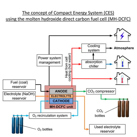
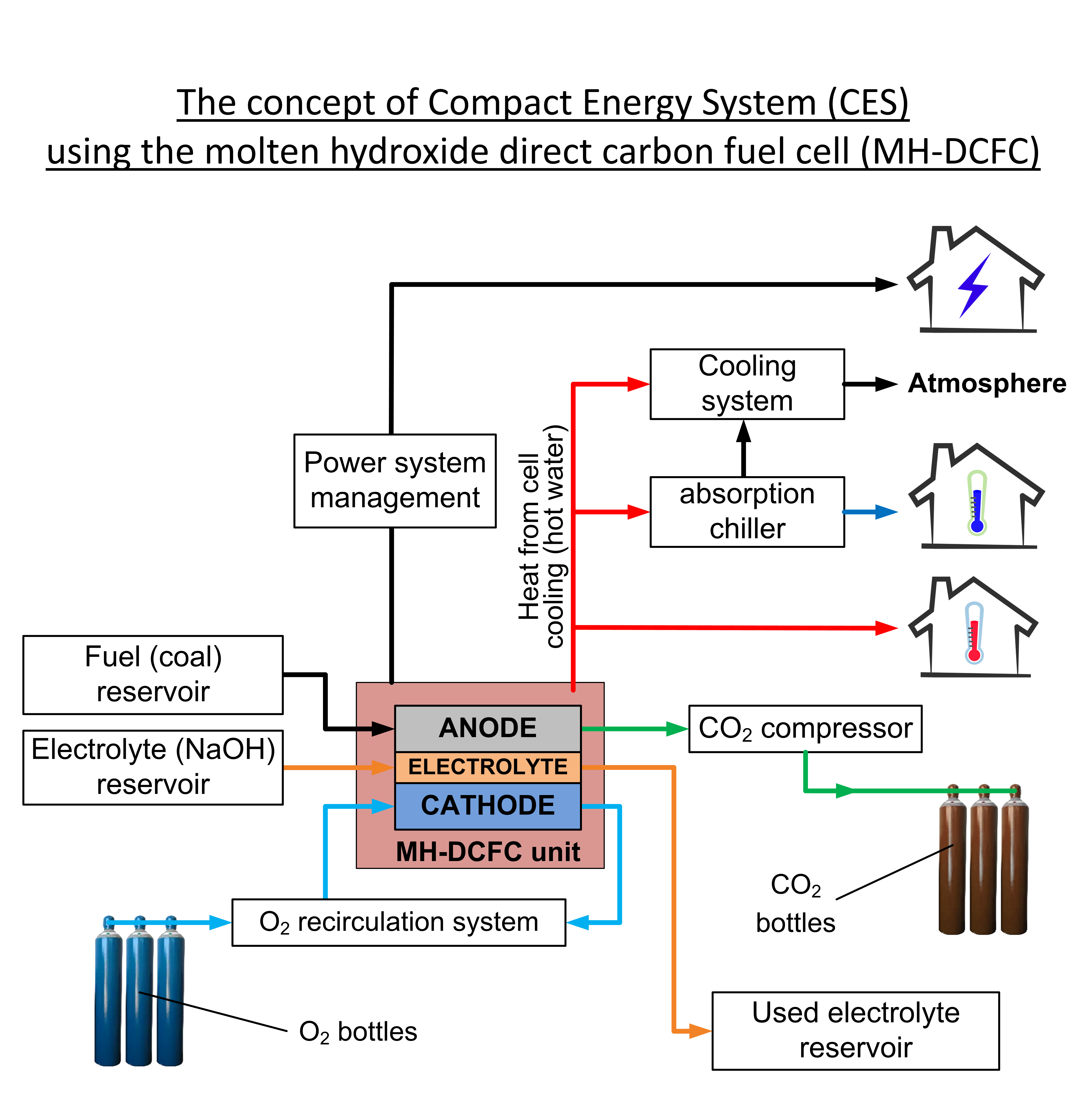
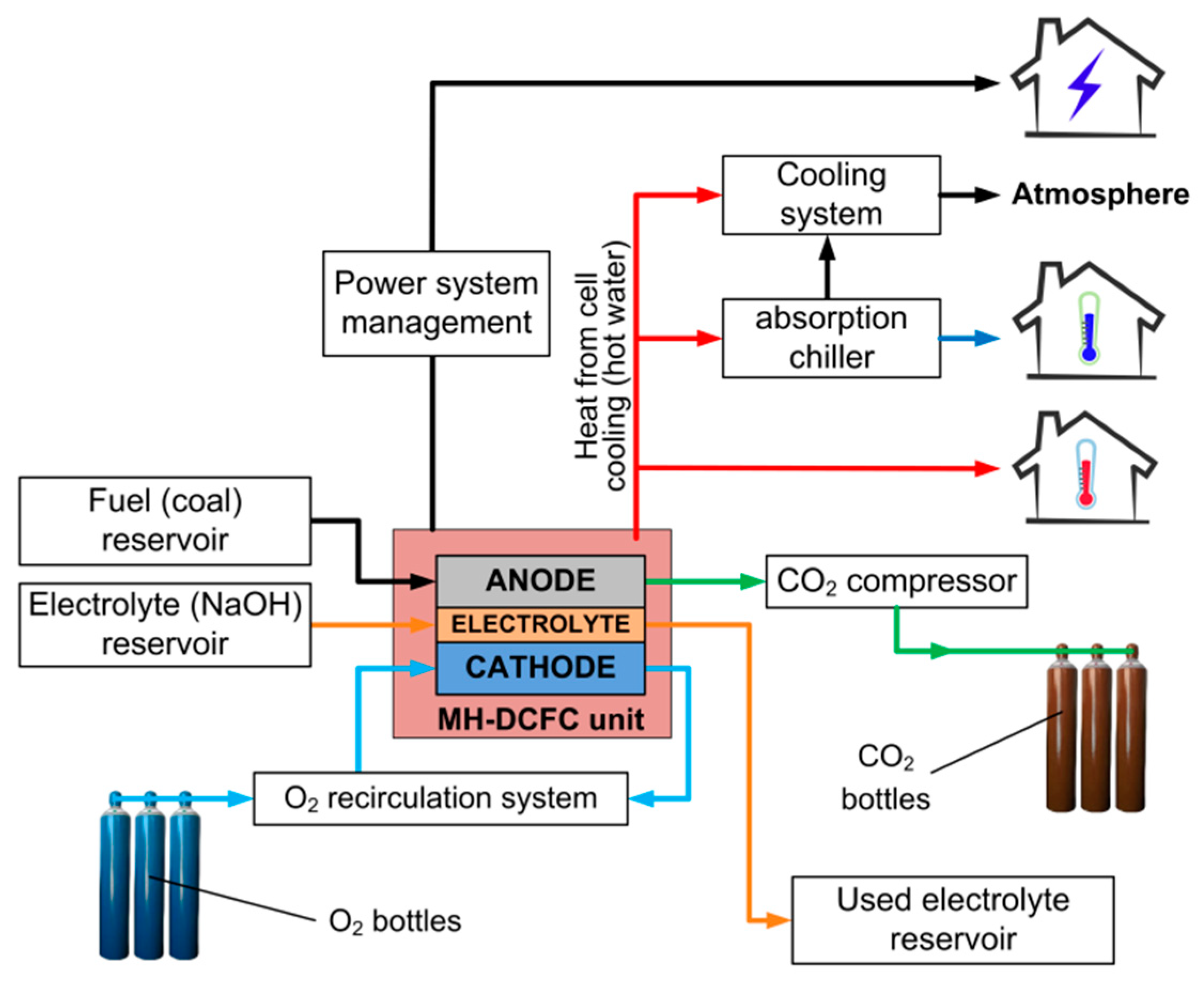
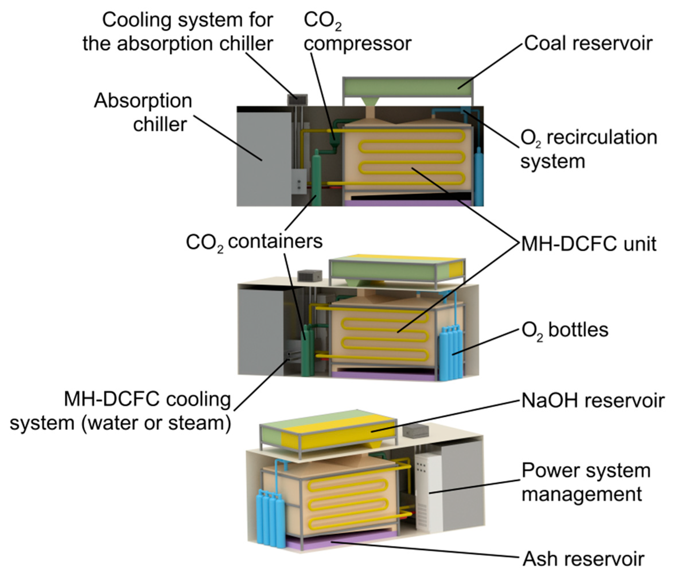
2. MH-DCFC and Concept of Compact Energy System Overview
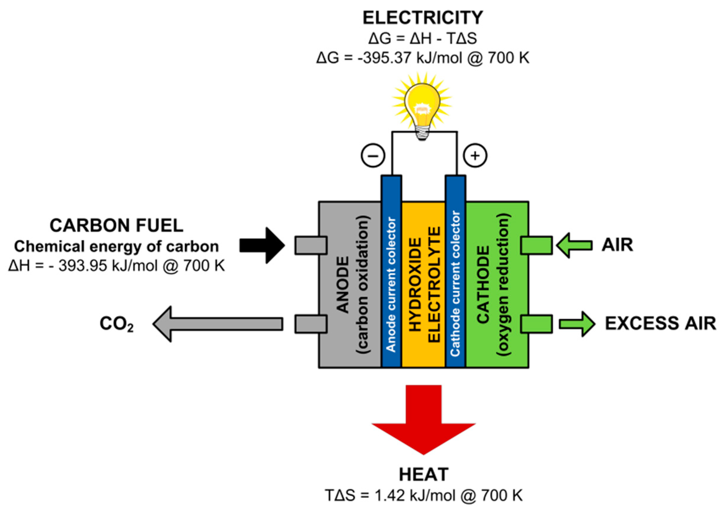
- Anode reaction:C + 4OH− → CO2 + 2H2O + 4e−
- Cathode reaction:4e− + O2 + 2H2O → 4OH−
- Overall reaction:C + O2 → CO2
3. MH-DCFC Module and Cogeneration System Characteristics
- Supplying the cell module in the container to the user (electrolyte is already in liquid state and fuel cell is in standby mode)—connecting the cell module with the current infrastructure (installation for hot water, chilled water and electricity).
- Fuel cell operation: production of electricity, heat and cold to meet the user needs. Replenishment of fuel and oxygen (exchange of bottles), exchange of the buffer with ash and consumed electrolyte, reception of liquid CO2.
- Transport of the cell to the place of electrolyte regeneration (electrolyte in the liquid state), inspection and repairing the cell, electrolyte regeneration.
- (A)
- Generation of electricity (Pe = 25 kWe) and heat (Pth = 20 kWth) with ratio Pe/Pth of 1.25;
- (B)
- Generation of electricity and storage of heat in molten electrolyte;
- (C)
- Generation of electricity and cold using an absorption chiller;
4. Results
4.1. Variant A
4.2. Variant B
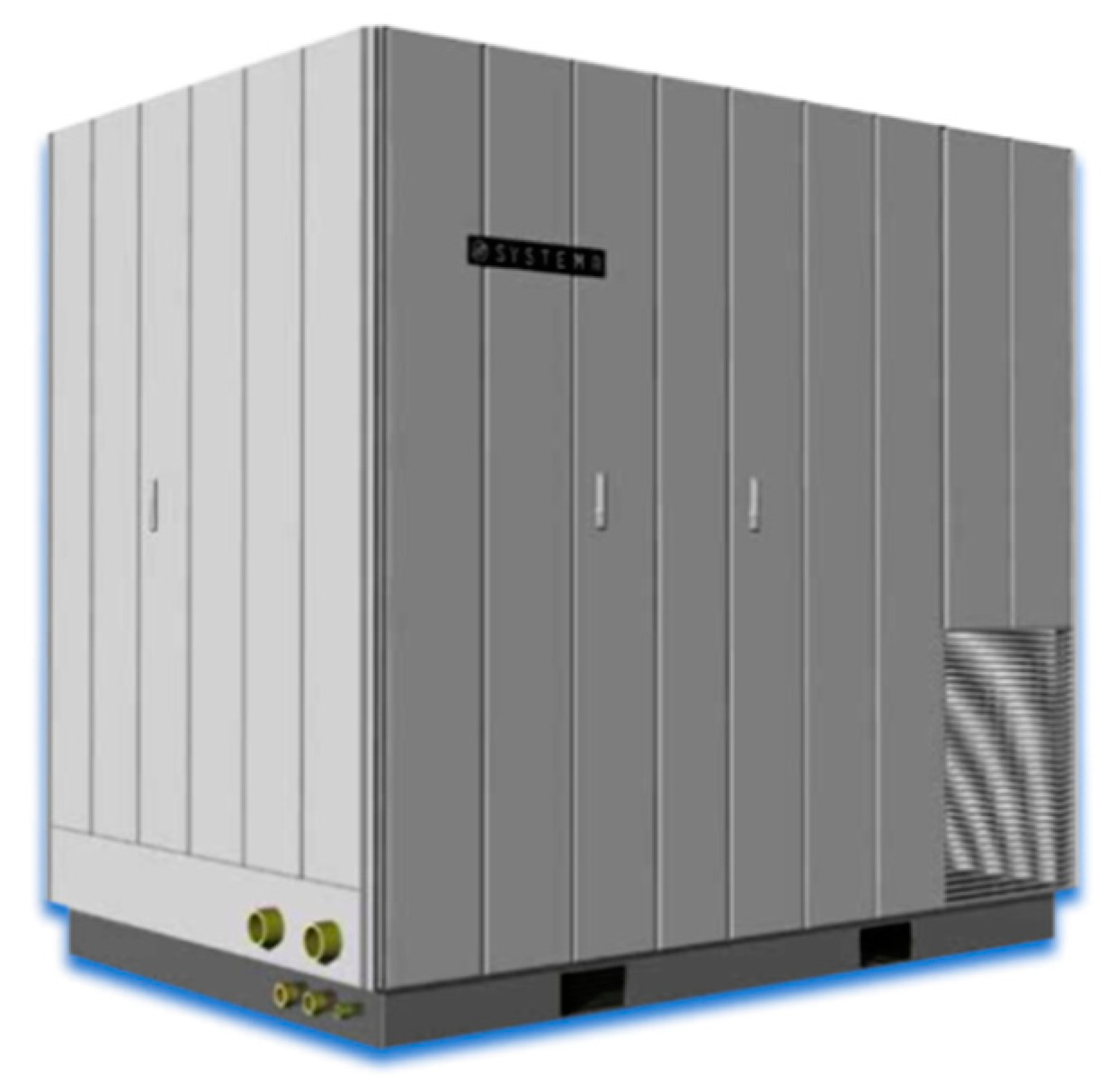
4.3. Variant C
5. Conclusions
Author Contributions
Funding
Conflicts of Interest
References
- International Energy Agency. World Energy Outlook 2017; International Energy Agency: Paris, France, November 2017. [Google Scholar]
- World Energy Council. World Energy Resources; World Energy Council: London, UK, 2016. [Google Scholar]
- Medunić, G.; Mondol, D.; Rađenović, A.; Nazir, S. Review of the latest research on coal, environment, and clean technologies. Rudarsko-Geološko-NaftniZbornik 2018, 33, 13–21. [Google Scholar] [CrossRef]
- Yue, G.; Li, S. (Eds.) Clean Coal Technology and Sustainable Development: Proceedings of the 8th International Symposium on Coal Combustion; Springer: Berlin, Germany, 2016. [Google Scholar]
- Chowdhury, M.M.R. Essence of international environmental law to address the effects of climate change. In Emerging Economic Models for Global Sustainability and Social Development; Christiansen, B., Sysoeva, I., Udovikina, A., Ketova, A., Eds.; IGI Global: Hershey, PA, USA, 2018; Chapter 12; pp. 220–236. [Google Scholar]
- Akpan, U.F.; Akpan, G.E. The contribution of energy consumption to climate change: A feasible policy direction. Int. J. Energy Econ. Policy 2011, 2, 21–33. [Google Scholar]
- Energy Climate and Change; World Energy Outlook Special Report; IEA: Paris, France, 2015.
- Lefèvre, N. Energy Security and Climate Policy: Assessing Interactions; OECD/IEA: Paris, France, 2007. [Google Scholar]
- Badwall, S.; Giddey, S. The holy grail of carbon combustion—The direct carbon fuel cell technology. Mater. Forum 2010, 34, 181–185. [Google Scholar]
- Giddey, S.; Badwal, S.P.S.; Kulkarni, A.; Munnings, C. A comprehensive review of direct carbon fuel cell technology. Prog. Energy Combust. Sci. 2012, 38, 360–399. [Google Scholar] [CrossRef]
- Kacprzak, A. Hydroxide electrolyte direct carbon fuel cells—Technology review. Int. J. Energy Res. 2018, 1–21. [Google Scholar] [CrossRef]
- Desclaux, P.; Rzepka, M.; Stimming, U.; Hempelmann, R. Actual state of technology in direct carbon fuel cells. Z. Phys. Chem. 2013, 227, 627–649. [Google Scholar] [CrossRef]
- Deleebeeck, L.; Hansen, K.K. Hybrid direct carbon fuel cells and their reaction mechanisms—A review. J. Solid State Electr. 2014, 18, 861–882. [Google Scholar] [CrossRef]
- Munnings, C.; Giddey, S.; Badwal, S. Direct carbon fuel cells: An ultra-low emission tech for power generation. Cornerstone 2014, 2, 56–60. [Google Scholar]
- Chen, L.; Zhang, H.; Gao, S.; Yan, H. An available method utilizing the waste heat in a direct carbon fuel cell. Int. J. Electrochem. Sci. 2014, 9, 5788–5802. [Google Scholar]
- Yang, Z.; Peng, W.; Liao, T.; Zhao, Y.; Lin, G.; Chen, J. An efficient method exploiting the waste heat from a direct carbon fuel cell by means of a thermophotovoltaic cell. Energy Convers. Manag. 2017, 149, 424–431. [Google Scholar] [CrossRef]
- Parise, J.A.; Vargas, J.V.; Marques, R.P. Fuel cells and cogeneration. J. Fuel Cell Sci. Technol. 2008, 5, 034002. [Google Scholar] [CrossRef]
- Malico, I.; Carvalhinho, A.P.; Tenreiro, J. Design of a trigeneration system using a high-temperature fuel cell. Int. J. Energy Res. 2009, 33, 144–151. [Google Scholar] [CrossRef]
- Samavati, M.; Raza, R.; Zhu, B. Design of a 5-kW advanced fuel cell polygeneration system. Wiley Interdiscip. Rev. Energy Environ. 2012, 1, 173–180. [Google Scholar] [CrossRef]
- Adams, T.A., II; Barton, P.I. Combining coal gasification, natural gas reforming, and solid oxide fuel cells for efficient polygeneration with CO2 capture and sequestration. Fuel Process. Technol. 2011, 92, 2105–2115. [Google Scholar] [CrossRef]
- Kacprzak, A.; Kobyłecki, R.; Włodarczyk, R.; Bis, Z. Efficiency of non-optimized direct carbon fuel cell with molten alkaline electrolyte fueled by carbonized biomass. J. Power Sources 2016, 321, 233–240. [Google Scholar] [CrossRef]
- Kacprzak, A.; Włodarczyk, R.; Kobyłecki, R.; Ścisłowska, M.; Bis, Z. Fuel cell as part of clean technologies. In Environmental Engineering IV; Pawłowski, A., Dudzińska, M.R., Pawłowski, L., Eds.; CRC Press, Taylor & Francis Group: London, UK, 2013; pp. 443–450. ISBN 978-0-415-64338-2. [Google Scholar]
- Kacprzak, A.; Kobyłecki, R.; Bis, Z. Influence of temperature and composition of NaOH-KOH and NaOH-LiOH electrolytes on the performance of a direct carbon fuel cell. J. Power Sources 2013, 239, 409–414. [Google Scholar] [CrossRef]
- Kacprzak, A.; Kobyłecki, R.; Włodarczyk, R.; Bis, Z. The effect of fuel type on the performance of a direct carbon fuel cell with molten alkaline electrolyte. J. Power Sources 2014, 255, 179–186. [Google Scholar] [CrossRef]
- Kacprzak, A.; Kobyłecki, R.; Bis, Z. The effects of operating conditions on the performance of a direct carbon fuel cell. Arch. Thermodyn. 2013, 34, 187–197. [Google Scholar] [CrossRef]
- Douglas, T.B.; Dever, J.L. Anhydrous sodium hydroxide: The heat content from 0 degrees to 700 degrees C, the transition temperature, and the melting point. J. Res. Natl. Bur. Stand. 1954, 53, 2519. [Google Scholar] [CrossRef]
- Incropera, F.P.; DeWitt, D.P.; Bergman, T.L.; Lavine, A.S. Fundamentals of Heat and Mass Transfer, 6th ed.; John Wiley & Sons, Inc.: Hoboken, NJ, USA, 2007. [Google Scholar]
- Systema Product Catalog: Package and Skid, Absorption Systems. Available online: https://www.systemaspa.si/images/pdf/Katalog_cooling_EN.pdf (accessed on 15 April 2018).


| Efficiency Parameter | Equation | Description | Value |
|---|---|---|---|
| Theoretical efficiency (ηth) | ΔG—Gibbs free energy change of overall MH-DCFC reaction (3); maximum available electrical work (ΔG700K = −395.37 kJ mol−1), ΔH—enthalpy change of reaction (3); total chemical energy available in the fuel (ΔH700K = −393.95 kJ mol−1). | 1.004 | |
| Energy efficiency (ηe) and correspondent voltage or electric efficiency (ηv) | Pel—electric power produced by cell (J), Pfuel,consumed—consumed fuel power (J), U—actual cell voltage (V), E—ideal cell voltage (V). | 0.59 (theoretically 0.64) | |
| Fuel utilization efficiency (ηf) (also called coulombic efficiency or faradaic efficiency) | Ccalc—calculated carbon consumption for current generation, Creal—actual carbon consumption. | 0.95 (theoretically 1.00) | |
| Overall net efficiency (ηfc) | - | 0.56 (theoretically 0.64) |
| 20′ Container | 40′ Container | ||
|---|---|---|---|
| External dimensions | length | 6.058 m | 12.192 m |
| width | 2.438 m | 2.438 m | |
| height | 2.591 m | 2.591 m | |
| Interior dimensions | length | 5.867 m | 12.032 m |
| width | 2.352 m | 2.352 m | |
| height | 2.385 m | 2.385 m | |
| Internal volume | 33.1 m3 | 67.5 m3 | |
| Maximum gross weight | 30,400 kg | 30,400 kg | |
| Empty weight | 2200 kg | 3800 kg | |
| Net load | 28,200 kg | 26,200 kg | |
| Parameter | Value |
|---|---|
| Fuel cell power per electrolyte volume | 2086.3 We/m3electrolyte |
| Operating temperature range | 673–973 K |
| Electrolyte density at temperature of 723 K | 1722 kg/m3 |
| Electrical efficiency of fuel cell | 55.5% |
| t(K) | c(J kg−1 K−1) |
|---|---|
| 100 | 232 |
| 200 | 383 |
| 400 | 485 |
| 600 | 592 |
| 800 | 530 |
| 1000 | 562 |
| 1200 | 594 |
| 1500 | 616 |
| Absorption Chiller SYBCTDH70 (45)85/95 | ||
| Max. cooling capacity with supply of water (95°C) | kW | 45 |
| Chilled Water | ||
| Delivery water temperature | °C | 7 |
| Return water temperature | °C | 11.5 |
| Flow rate | m3/h | 8.6 |
| Useful heat | mH2O | 11 |
| Hot Water Supply | ||
| Inlet temperature | °C | 95 |
| Outlet temperature | °C | 85 |
| Supply water | m3/h | 5.37 |
| Available inlet heat | kW | 60 |
| General Data | ||
| Weight | kg | 2.100 |
| Dimensions (L × P × H) | m | 2.25 × 1.61 × 2.23 |
© 2018 by the authors. Licensee MDPI, Basel, Switzerland. This article is an open access article distributed under the terms and conditions of the Creative Commons Attribution (CC BY) license (http://creativecommons.org/licenses/by/4.0/).
Share and Cite
Zarzycki, R.; Kacprzak, A.; Bis, Z. The Use of Direct Carbon Fuel Cells in Compact Energy Systems for the Generation of Electricity, Heat and Cold. Energies 2018, 11, 3061. https://doi.org/10.3390/en11113061
Zarzycki R, Kacprzak A, Bis Z. The Use of Direct Carbon Fuel Cells in Compact Energy Systems for the Generation of Electricity, Heat and Cold. Energies. 2018; 11(11):3061. https://doi.org/10.3390/en11113061
Chicago/Turabian StyleZarzycki, Robert, Andrzej Kacprzak, and Zbigniew Bis. 2018. "The Use of Direct Carbon Fuel Cells in Compact Energy Systems for the Generation of Electricity, Heat and Cold" Energies 11, no. 11: 3061. https://doi.org/10.3390/en11113061
APA StyleZarzycki, R., Kacprzak, A., & Bis, Z. (2018). The Use of Direct Carbon Fuel Cells in Compact Energy Systems for the Generation of Electricity, Heat and Cold. Energies, 11(11), 3061. https://doi.org/10.3390/en11113061