Article

On the Design of In-Wheel-Hub Motor Transmission Systems with Six-Link Mechanisms for Electric Vehicles

Mechanical Engineering Department, National Cheng Kung University, No.1 University Road, Tainan 70101, Taiwan
*
Author to whom correspondence should be addressed.
Energies 2018, 11(11), 2920; https://doi.org/10.3390/en11112920
Submission received: 3 September 2018 / Revised: 18 October 2018 / Accepted: 24 October 2018 / Published: 26 October 2018
(This article belongs to the Section F: Electrical Engineering)

Abstract

:
Nowadays, there are several electric vehicles (EV) on the market, due to the innovation of technology that promotes new components such as batteries, transmissions, and electric motors. This study proposes the design procedure for the configuration synthesis and simulation of in-wheel-hub motor transmissions with six-link mechanisms. The synthesis process shows six mechanisms with six members and eight joints, 15 new clutchless motor transmissions, and 16 new clutched motor transmissions. A novel motor transmission with the possibility of synthesized configurations is chosen as a case to analyze the working rules connected with the power flow modes and operation modes. Moreover, this design is modeled for the simulation process that generates the results of the operation mode transition and energy regulation.

1. Introduction

Many powertrain architectures have been designed and analyzed [1,2,3,4,5,6,7,8,9,10]. Yang et al. [11] compared the fuel economy, transmission complexity, and exhaust gases of some popular electrified transmissions, alongside traditional transmissions, and the electric vehicle is one of the best choices, offering the greatest fuel economy, lowest transmission complexity, and zero exhaust gases (see Figure 1).
In 1998, Weiss [12] proposed an electric wheel drive for a utility vehicle that includes an output shaft with an electric motor that drives the final gear train to reduce the turning speed of the driven wheel. A powertrain is arranged between the final gear train and the electric motor, and it can move between at least two turning speed powertrain ratios. The wheel drive makes it possible to obtain a wide range of vehicle speeds with the use of low-cost, commercially accessible electric motors. With the rule working speed of the vehicle, the design speed of the electric motor is consistent and general high vehicle speeds are possible.
Jing He et al. [13] took out patents on a system utilizing multiple motors in 2012. The system employed a basic planetary gear train (PGT), such as the transmission. The ring gear is attached to the motor, the sun gear is attached to the flywheel, and the carrier is attached to the output shaft. The system proposes a dual motor to increase the power and operation modes. The system demonstrates the combination of many motors to regulate energy for controlling series operation modes.
In 2014, Daisuke Gunji et al. [14] presented the wheel hub motor, which can fit inside a 16-inch wheel, and incorporates two separate motors and a transmission consisting of two planetary gears that can deliver both high drive torque and high speeds. By controlling the torque and the speed of the two motors, the transmission system provides smooth gear-changing, even during acceleration. During high-gear operation, the two motors revolve in the same direction. When low gearing is needed, they revolve in opposite directions. After that, NSK used this patent and improved on the real vehicle in 2017 [15]. It is now looking to commercialize specific components, including the wheel hub bearing with an integrated speed reducer, one-way clutch, and wheel hub motor.
Configuration designs have been presented in previous research. For example, Bayrak et al. [16] presented a modified bond graph theory of transmission configuration to generate possible hybrid and battery electric configurations, while Xie et al. [17] developed a synthesis algorithm by applying the improved graph theory of the shifted input and variably hard interconnection link.
With the improved methodology of Yan for the procedural generation of novel possible configurations for HEVs [18,19], Hoang and Yan synthesized possible configurations of series-parallel hybrid transmissions using twelve joints and eight members [20]. Based on such a method, this study describes a procedure for the configuration synthesis and simulation of in-wheel-hub motor transmissions with six-link mechanisms (see Figure 2). This approach shows all the steps from the existing design process analyzed, to the configuration synthesis, the system analysis, and the system simulation.
This procedure presents an analysis of existing designs, demonstrating the topological characteristics and design specifications in Section 2. Depending on the GKCs, an Atlas of six-link mechanisms for motor transmissions is presented in Section 3. After that, the procedure relating to the operation modes, clutch arrangements, and power arrangements is considered in Section 4. Following the presentation of the Atlas of novel feasible motor transmissions in Section 4, the functions, operation modes and specifications for the next process are described, including the dynamic analysis and system specifications, in Section 5. Section 6 describes the computer simulation of the novel motor transmission built with MATLAB/SIMULINK. Finally, Section 7 presents the conclusion of this study.

2. Existing Motor Transmissions

Firstly, existing designs of motor transmissions with six links and eight joints are identified and analyzed, including the topological characteristics and design specifications of existing designs, such as the numbers and types of joints and links, the adjacencies of the links, and the diagram conversions.

2.1. Diagram Conversions

By analyzing the existing design in Reference [21], Figure 3a presents the schematic diagram, Figure 3b shows the block diagram, and Figure 3c provides the respective generalized kinematic chain (GKC). The topological characteristics are summarized below:
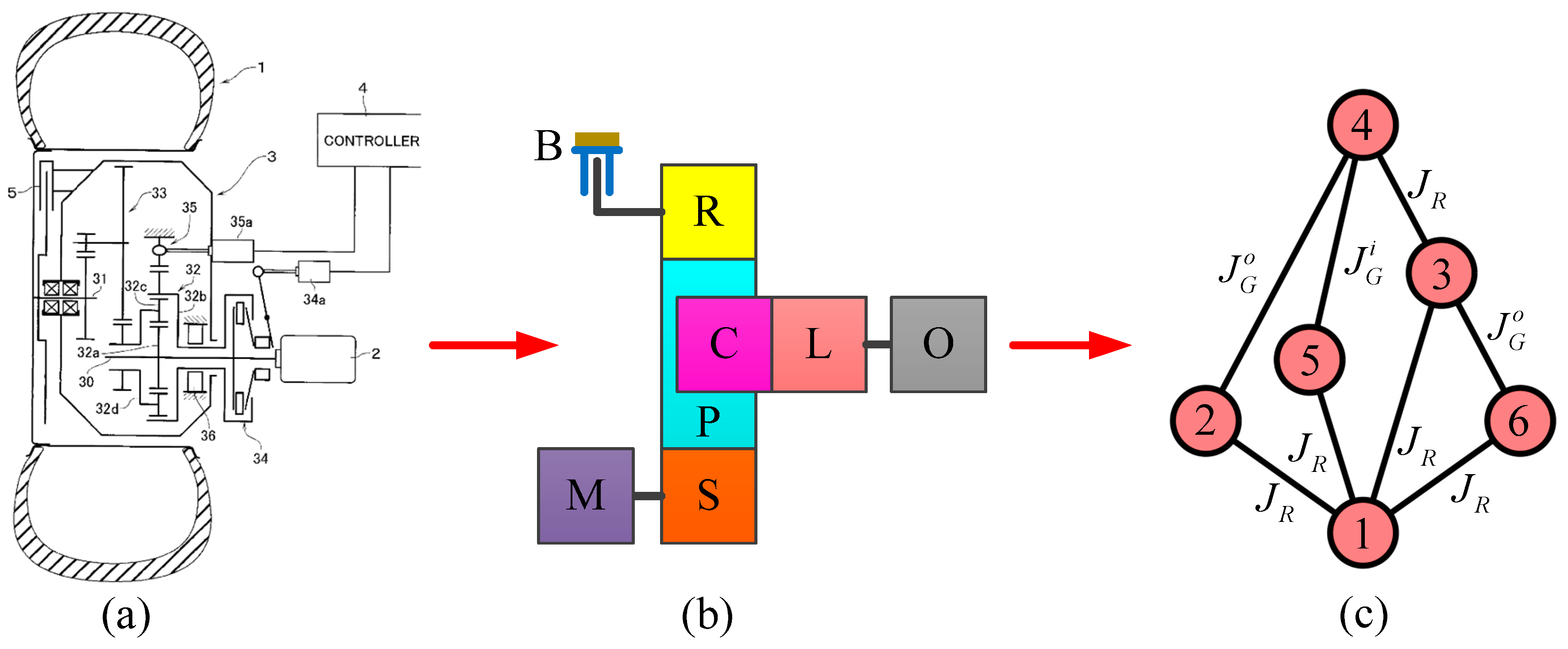
  • This is a planetary gear train with a 2-DoF mechanism, which connects a simple PGT and a link.
  • This mechanism comprises six members containing a ground link (G: member 1), a sun gear (S: member 2), a carrier (C: member 3) connected to the planet gears (P: member 4), a ring gear (R: member 5), and an additional link (L: member 6), which is connected to the carrier.
  • This mechanism has eight joints which have three gear pairs (JG) with two external gear pairs ( J G o ), one internal gear pair ( J G i ), and five revolute joints (JR).
  • This mechanism has a ground link connected to the four members.
A 2-DoF planetary gear train should correspond to the following expressions [18]:
N J = 2 N L 4 ,
N J R = N L 1 ,
N J G = N L 3 ,
where the numbers of the joints, revolute joints, gear joints, and members are denoted by NJ, NJR, NJG, and NL, respectively.
The process of generalization transfers the existing design to the schematic diagram, which includes various types of joints and members in its block diagram and the respective GKC based on a set of generalization laws. The respective GKC presented in Figure 3c has eight generalized joints and six generalized links. There are nine GKCs for the mechanisms using eight joints and six members, as shown in Figure 4, following the number synthesis of GKCs.

2.2. Design Constraints

From GKCs, the possible specialized chains are determined based on the design constraints, including the output/inputs constraints and mechanical constraints.

2.2.1. Mechanical Constraints

The ground link (G: member 1):
  • The ground link should be a hard connection member.
  • A quaternary or ternary link should be applied to the ground link.
The planet gear (P: member 4):
  • The ground link will not be connected to the planet gear.
  • The ground link, binary link, and planet gear will be not connected to the three-bar loop.
  • Each planet gear will be connected only to one carrier.
Carrier (C: member 3):
  • The carrier will be connected to the ground link (member 1) and all the planet gears.
The sun gear, ring gear, and remaining member(s) (S: member 2, R: member 5, and L: member 6):
  • In a PGT, there should be at least one ring gear and one sun gear.
  • The planet gear and the ground link should be connected to both the ring gear and the sun gear.
  • The remaining member(s) should be connected to any member in the mechanism.
Revolute joints (JR):
  • There are five revolute joints in this mechanism.
  • Between the carrier and its planet gears there should be the revolute joint and the binary link. The ground link should also be the revolute joint.
The gear pairs (JG):
  • There are three gear pairs, including the internal gear joints ( J G i ) and the external gear joints ( J G o ).
  • The gear pairs should be set between the sun gear or the ring gear and the planet gear.

2.2.2. Output/Inputs Constraints

The output (O)
  • The output shaft should be connected to a member of the mechanism.
  • When the motors drive the vehicle to upgrade high torque, the planetary carrier or the ring gear should be connected to the output shaft.
  • When the third member is held in the PGT set, the output shaft speed should be slower than the motor speed.
Motor 1 (M1)
  • Motor shaft 1 should be connected to a member of the mechanism.
  • When the vehicle reaches high torque and speed reduction at the output shaft, the ring gear or the sun gear should be connected to motor 1.
  • The motor 1 speed should be higher than the motor 2 speed.
  • To avoid excessive output speed, the carrier should not be connected to motor 1.
Motor 2 (M2)
  • Motor shaft 2 should be connected to a member of the mechanism.
  • When the vehicle reaches a high speed, the carrier or the ring gear should be connected to motor 2.

3. Feasible Mechanism Designs

There are only three GKCs with eight joints and six links from the nine possible GKCs considered above with the design constraints, as shown in Figure 4d,g,i. Depending on the design constraints, the respective GKCs are identified with the following steps:
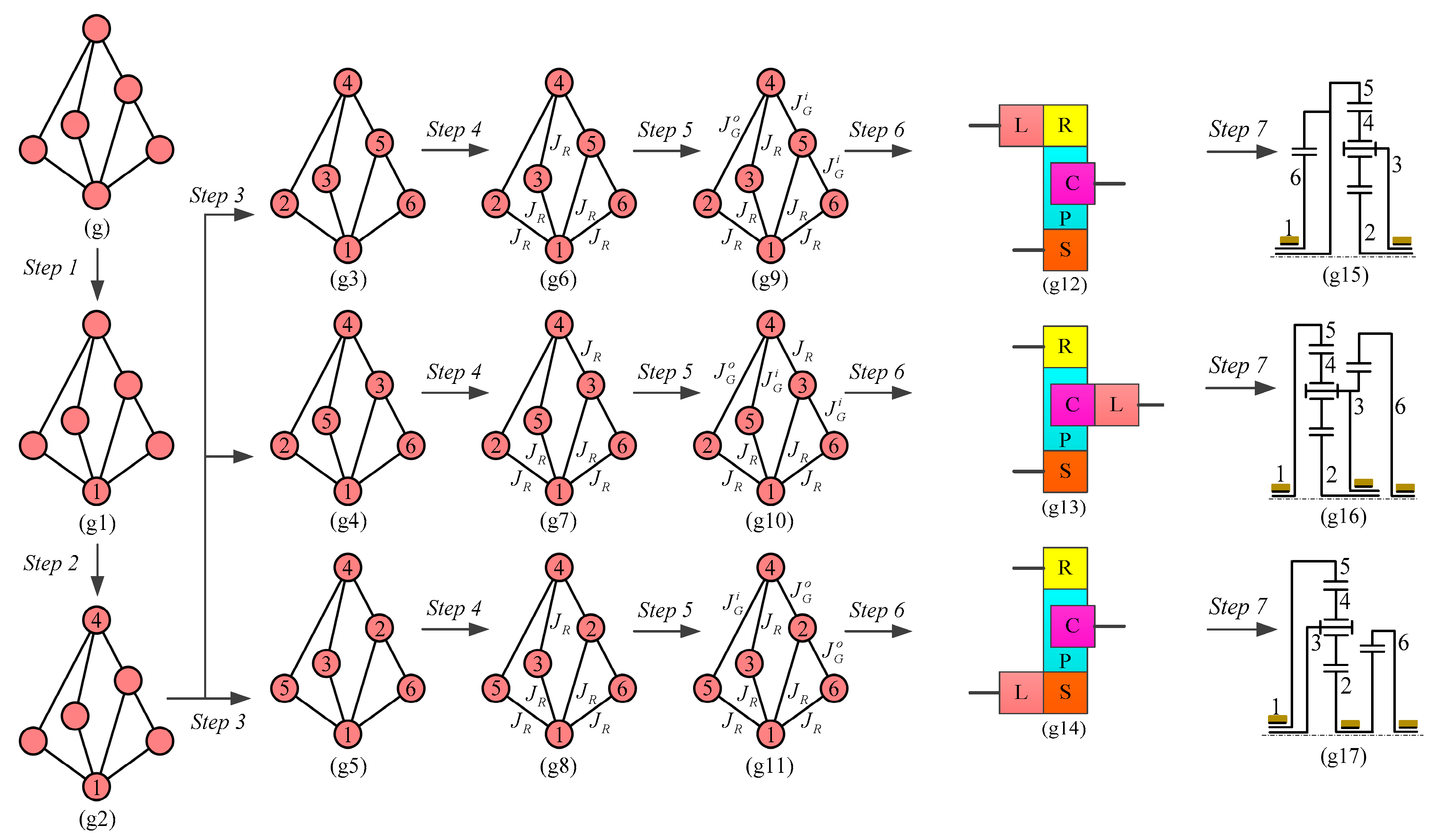
  • Step 1: Nominate the ground link. As shown in Figure 5(g1), the ground link is nominated for each GKC.
  • Step 2: Nominate the planet gear(s). The planet gear(s) is/are nominated for each result in Step 1, as shown in Figure 5(g2).
  • Steps 3: Nominate the ring (sun) gear, carrier, and remaining member(s). The ring (sun) gear and the carrier are nominated for each result in Step 2. Then, the remaining member(s) is/are also nominated, as shown in Figure 5(g3–g5).
  • Step 4: Nominate the revolute joints (JR). The revolute joints are nominated for each result in Step 3, as shown in Figure 5(g6–g8).
  • Step 5: Nominate the gear pairs (JG). The internal gear pairs and the external gear pairs (JiG and JoG) are nominated for each result in Step 4, as shown in Figure 5(g9–g11).
  • Step 6: Transfer to block diagrams. There are three specialized chains transferred to their respective block diagrams for each result in Step 5, as shown in Figure 5(g12–g14).
  • Step 7: Transfer to schematic diagrams. There are also three block diagrams transferred to their respective schematic diagrams for each result in Step 6, as shown in Figure 5(g15–g17).
By using the GKCs shown in Figure 4g, three possible respective specialized chains are generated by applying the procedure above, as shown in Figure 5. Through particularization, the transferred diagram procedure of generalization regenerates the respective schematic diagrams of the possible specialized chains. As shown in Figure 6, each possible specialized chain obtained above is transferred to its respective diagram. Moreover, there are six possible specialized chains, transferred to six block diagrams and six schematic diagrams, respectively. In addition, Figure 6(a1,b1,a3,b3) show the double planet PGT and the original mechanism.

4. Atlas of Motor Transmissions

In this section, the procedure of the operation modes, the clutch arrangement, and the power arrangement will be considered.

4.1. The Power Arrangement

This is the power arrangement procedure to nominate the output and the inputs to the mechanisms. The system shown in Figure 6(a2) has been chosen as a case to illustrate the procedure. Depending on the design constraints for the output/inputs, the motors and output are nominated to each system with the following three steps:
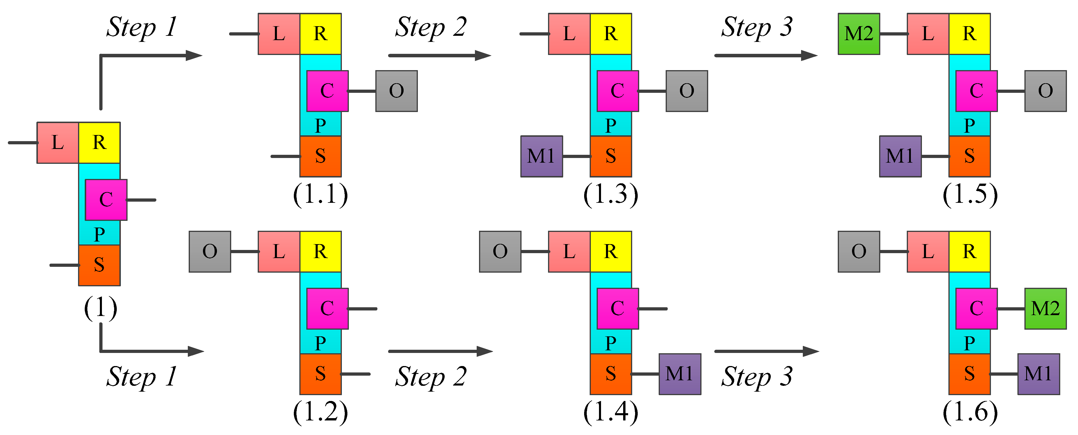
  • Step 1: Nominate the Output (O). The output is nominated for this mechanism. As shown in Figure 7(1.1,1.2), two results are created.
  • Step 2: Nominate Motor 1 (M1). Motor 1 is nominated for each result in Step 1. As shown in Figure 7(1.3,1.4), the nomination of motor 1 creates two results.
  • Step 3: Nominate Motor 2 (M2). Motor 2 is nominated for each result in Step 2. As shown in Figure 7(1.5,1.6), the nomination of motor 2 creates two results.
By using this procedure for the remaining mechanisms, 15 systems determining the output, motor 1, and motor 2 are created, respectively, for the six mechanisms obtained. Figure 8 shows the atlas of motor transmission systems without a clutch and brake.

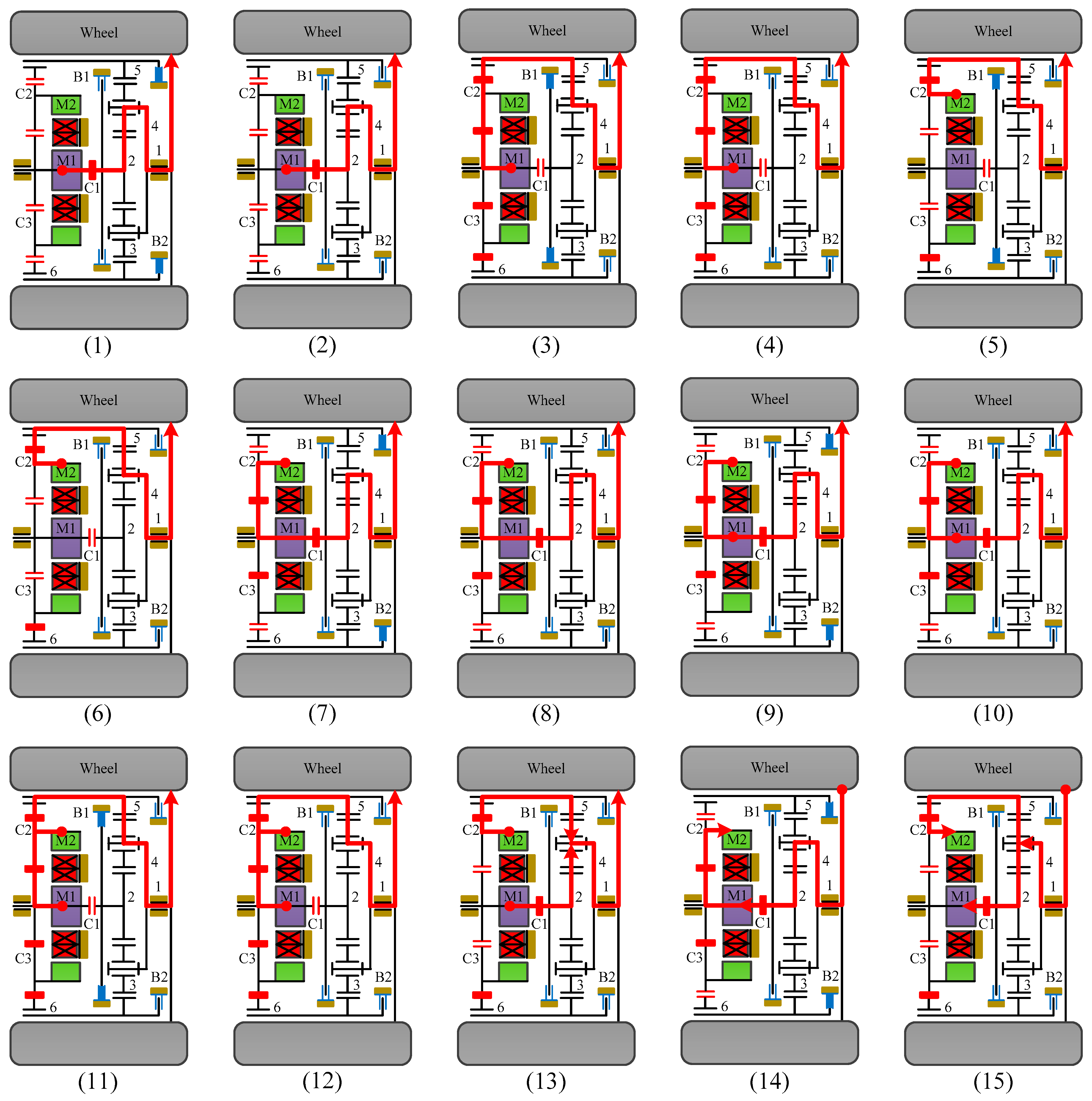
4.2. The Clutch Arrangement

In the clutch arrangement procedure, the clutches and brakes are nominated to the system to control the operation modes determining the possible operation modes. There are two steps that conclude the clutch arrangement and the required operation modes.
a. The required operation modes
Depending on the vehicle operating conditions, as presented by Mi et al. [22], the operation modes of novel systems are chosen to develop novel motor transmission systems, which is the purpose of this study. The procedure is identified with the following steps:
  • Motor 1 mode: The vehicle is driven only by motor 1 when the vehicle requires high torque to begin running or climb a hill.
  • Motor 2 mode: Motor 2 mode is shifted to the transmission to better support efficiency when the vehicle requires higher demand power while in cruise control on the highway.
  • Combined power mode: The vehicle requires higher demand power for high-speed acceleration or a heavy load; the combined power mode is shifted to the transmission by connecting motor 1 and motor 2 to provide more power.
  • Regenerative braking mode: The battery will be charged during the braking procedure of the vehicle, when the electric motor works as a generator to transfer kinetic energy to electrical energy.
b. The clutch arrangement
Depending on the power source status and the operation mode in each case, the procedure is applied to attach the brakes and clutches to each system, and a minimal number of clutches and brakes is required to conclude the operation modes. These systems are shown in Figure 8(2,10) and a case has been selected to illustrate the clutch arrangement procedure, as shown in Figure 9.
  • Step 1: M1 mode. As with the 1-DoF system, when the vehicle is driven by motor 1, motor 1 mode will be required. As shown in Figure 9(2.1,10.1), each result is created by adding the clutches and brakes.
  • Step 2: M2 mode. As with the 1-DoF system, when the vehicle is driven by motor 2, motor 2 mode will be required. As shown in Figure 9(2.2,10.2), each result is created by adding the clutches and brakes.
  • Step 3: Combine mode. Because the system becomes 2-DoF, the output shaft can be connected to both motors, as shown in Figure 9(2.3,10.3).
A total of 16 clutched transmission systems are synthesized for the novel motor transmissions by using this procedure for all clutchless transmission systems, as presented in Figure 10.

5. System Analysis

This section describes the modeling to identify the functions, operation modes and specifications for the simulation process, including the dynamic analysis and the system specifications.

5.1. The Dynamic Analysis

To focus on the probability of the synthesized novel motor transmissions, the system shown in Figure 10(12) has been selected as a case to present the power flow analysis and the operation mode analysis of the novel system (see Figure 11). The operation modes described in Figure 12 are split into 15 feasible clutching conditions, similarly to Table 1, where an “x” shows that the respective clutches or the brakes are attached. Gear teeth are chosen for the ring gear, sun gear, planet gear, and L gear, such as 72 (60), 36, 54, and 40, respectively.
The relationship shown for the power and the torque provides the reference power values in each operation mode. In a particular operation, the possible operation modes are chosen depending on the required power of the vehicle. Furthermore, the more clutches and brakes are added to the transmission systems, the more operation modes can be performed to provide the flexible control method for EVs during operation, further improving energy economy.

5.2. The System Specifications

This section presents the required system specifications, such as vehicle specifications, environmental conditions, desired performance, and power source specifications, as shown in Table 2.

6. System Simulation

This section describes the computer simulation of the novel motor transmission built with MATLAB/SIMULINK (R2017b, The MathWorks, Inc., East Natick, MA, USA).

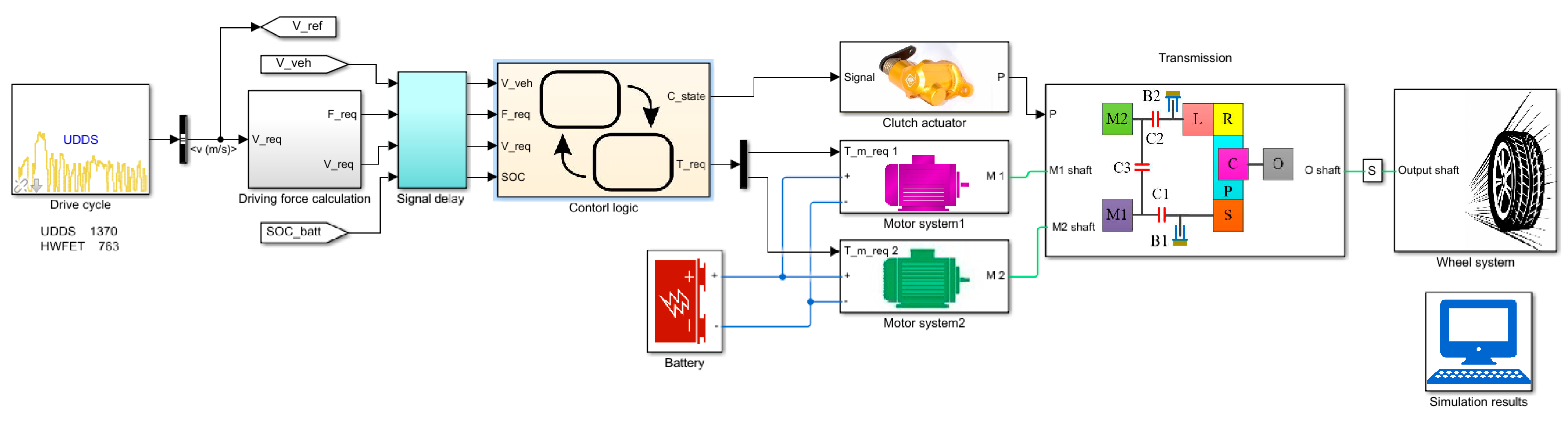
6.1. Simulation Structure

As shown in Figure 13, the simulation model is developed, and includes drive cycles, driving force calculation, control logic, the power source system, transmission, and the wheel system. The simulation results of the novel design relate to two drive cycles, comprising the Highway Fuel Economy Test (HWFET) and the Urban Dynamometer Driving Schedule (UDDS), as the two most popular cycles for automotive manufacturers.

6.2. Control Parameters

According to the actual vehicle speed, a feasible gear is selected through the gear determination process. According to the obtained reduction ratio and the required driving force, the minimum energy consumption of each 1-DoF operation mode is calculated. With the predicted energy consumptions and the vehicle driving conditions, the mode determination process is conducted to select the most suitable operation mode. Finally, the optimized torque demands for the power sources and the clutching signal are output.
In the gear determination process, the gear is selected to maintain the motors operating within the high-efficiency region; therefore, the suitable reduction ratio at that instant is obtained. Figure 14 shows the gear determination criterion. When the vehicle stops and the required driving force is zero, the gear state is 0; otherwise, the gear state is a positive integer. To maintain high motor efficiency, the gear state changes when the vehicle speed achieves the threshold speeds of each gear.
In the mode determination process, three basic states, including the parking state, driving state and regenerative braking state, are defined, as shown in Figure 15. In each state, the corresponding operation mode is available. When the vehicle is stopped, the vehicle shifts to the parking state. When the vehicle is moving but not braking, the mode state shifts to the driving state. When the vehicle torque demand is negative, the regenerative braking mode is selected.
In both driving states, the vehicle starts with the motors mode. According to the feasible mode shifts obtained with the shifting analysis, mode shifts among the modes in the same gear are always feasible. Therefore, the operation mode is selected according to the predicted energy consumptions when the vehicle exits the starting phase and enters the normal phase of the two driving states.

6.3. Simulation Results

The simulation results of the novel design regarding the two driving cycles are shown in Figure 16. The results evaluate the conversion of the gear states, the operation modes, and energy consumption in the urban driving condition, and the latter represents the highway driving condition.
Table 3 and Figure 17 present a comparison of the operation mode selection between UDDS and HWFET. The time and percentage of the operation modes maintained in the driving cycles show that the results are reasonable.
The results show a suitable translation of the operation modes in both UDDS and HWFEF. The reduction ratios also change in accordance with the wheel speed, and the energy consumption for each operation mode such as motor 1, motor 2, combined power and regeneration braking is reasonable. Therefore, this approach can be applied to the design and analysis of any motor transmission by following the steps in the analyzed existing design process, the configuration synthesis, the system analysis, and the system simulation.

7. Conclusions

This paper presented an analysis of existing designs, considering topological characteristics and design specifications in Section 2. Depending on the GKCs, an Atlas of six-link mechanisms for motor transmissions was presented in Section 3. After that, the procedure for the operation modes, clutch arrangement, and power arrangement was considered in Section 4. With the Atlas of novel feasible motor transmissions presented in Section 4, the functions, operation modes, and specifications for the next process were identified, including the dynamic analysis and system specifications, in Section 5. Section 6 described the computer simulation of a novel motor transmission built with MATLAB/SIMULINK. Finally, Section 7 presented the conclusions of the study.
A design procedure was proposed and illustrated based on an improved methodology of creative design to synthesize the possible mechanisms for the configurations of motor transmissions. The mechanisms were chosen to synthesize clutched and clutchless motor transmissions by applying the method of clutch docking and power docking. As a result, six PGTs were structurally synthesized for motor transmissions by applying the method of creative design techniques. Then, 15 clutchless and 16 clutched motor transmissions were synthesized. The desired operation modes and design constraints determine the number of mechanisms and motor transmissions. The different characteristic systems can be generated since some of the chosen operation modes offer a flexible selection for engineers.
After analyzing a novel motor transmission system, a computer simulation model was constructed to evaluate the translation of the operation modes in the UDDS and HWFET driving cycles. With this design approach, many motor transmissions can be synthesized, analyzed, and simulated to identify an Atlas of the best motor transmissions.

Author Contributions

This study is the result of a collaboration between N.-T.H. and H.-S.Y.; N.-T.H., who contributed to synthesizing the mechanism, designing the motor transmission, and preparing the manuscript. H.-S.Y. generated the methodology and edited the manuscript.

Funding

This research was funded by The Ministry of Science and Technology of Taiwan (MOST) grant number MOST 104-2221-E-006-059-MY3.

Acknowledgments

The Ministry of Science and Technology of Taiwan (MOST, R.O.C.) supported this work.

Conflicts of Interest

Hoang and Yan declare no conflicts of interest.

References

  1. Berman, B.; Gelb, G.; Richardson, N.; Wang, T. Power Train Using Multiple Power Sources. U.S. Patent 3,566,717, 2 March 1971. [Google Scholar]
  2. Hata, H.; Kojima, M.; Adachi, M.; Shimizu, T. Power Transmission System. U.S. Patent 7,081,060, 25 July 2006. [Google Scholar]
  3. Schmidt, M.R. Two-Mode, Compound-Split, Electro-Mechanical, Vehicular Transmission. U.S. Patent 5,558,589, 24 September 1996. [Google Scholar]
  4. Zhang, D.; Chen, J.; Hsieh, J.; Rancourt, J.; Schmidt, M.R. Dynamic modeling and simulation of two-mode electric variable transmission. Proc. Inst. Mech. Eng. Part D J. Automob. Eng. 2001, 215, 1217–1223. [Google Scholar] [CrossRef]
  5. Ai, X.; Anderson, S. An Electromechanical Infinitely Variable Speed Transmission. SAE Paper 2004-01-0354. In Proceedings of the SAE 2005 World Congress & Exhibition, Detroit, MI, USA, 11–14 April 2005. [Google Scholar]
  6. Villeneuve, A. Dual Mode Electric Infinitely Variable Transmission. In Proceedings of the SAE, Detroit, MI, USA, 8 March 2004; pp. 1–11. [Google Scholar]
  7. Hoeijmakers, M.J. The Electric Variable Transmission. IEEE Trans. Ind. Appl. 2006, 42, 1092–1100. [Google Scholar] [CrossRef]
  8. Turnbull, P.F.; Conlon, B.M.; Holmes, A.G.; Swales, S.H. Electrically Variable Transmission. U.S. Patent 8,585,520, 19 November 2013. [Google Scholar]
  9. Zhang, X.; Li, S.E.; Peng, H.; Sun, J. Efficient exhaustive search of power-split hybrid powertrains with multiple planetary gears and clutches. J. Dyn. Syst. Meas. Control 2015, 137, 121006. [Google Scholar] [CrossRef]
  10. Hoang, N.T.; Yan, H.S. Configuration Synthesis of Novel Series-Parallel Hybrid Transmission Systems with Eight-Link Ravigneaux Mechanisms. JCSME 2018, 34, 345–355. [Google Scholar]
  11. Yang, Y.; Arshad-Ali, K.; Roeleveld, J.; Emadi, A. State-of-the-art electrified powertrains-hybrid, plug-in, and electric vehicles. Int. J. Powertrains 2016, 5. [Google Scholar] [CrossRef]
  12. Weiss, H. Electric Wheel Drive for a Utility Vehicle. U.S. Patent 005,813,488, 29 September 1998. [Google Scholar]
  13. He, J.; He, H. Powertrain and Method for a Kinetic Hybrid Vehicle. U.S. Patent 0,196,713, 2 August 2012. [Google Scholar]
  14. Gunji, D.; Matsuda, Y.; Kimura, G. Wheel Hub Motor. U.S. Patent 008,758,178, 24 June 2014. [Google Scholar]
  15. NSK’s Website. Available online: http://www.nsk.com/company/news/2017/press0119a.html (accessed on 19 January 2017).
  16. Bayrak, A.E.; Ren, Y.; Papalambros, P.Y. Topology generation for hybrid electric vehicle architecture design. J. Mech. Des. 2016, 138, 081401. [Google Scholar] [CrossRef]
  17. Xie, T.; Hu, J.; Peng, Z.; Liu, C. Synthesis of seven-seed planetary gear trains for heavy-duty commercial vehicle. Mech. Mach. Theory 2017, 90, 230–239. [Google Scholar] [CrossRef]
  18. Yan, H.S. Creative Design of Mechanical Devices; Springer: Berlin, Germany, 1998. [Google Scholar]
  19. Ngo, H.T.; Yan, H.S. Configuration synthesis of series-parallel hybrid transmission. Proc. Inst. Mech. Eng. Part D J. Automob. Eng. 2015, 230, 664–678. [Google Scholar] [CrossRef]
  20. Hoang, N.T.; Yan, H.S. Configuration Synthesis of Novel Series-Parallel Hybrid Transmission Systems with Eight-Bar Mechanisms. Energies 2017, 10, 1044. [Google Scholar] [CrossRef]
  21. Kima, Y.; Hamada, T. Control Device for In-Wheel Transmissions in an Electric Vehicle. U.S. Patent 668,841B2, 10 February 2004. [Google Scholar]
  22. Mi, C.; Abul Masrur, M. Hybrid Electric Vehicle: Principles and Applications with Practical Perspectives; John Wiley & Sons: Hoboken, NJ, USA, 2011. [Google Scholar]
Figure 1. Powertrain comparisons and reasons why the electric vehicle (EV) market is growing.
Energies 11 02920 g001
Figure 2. The design process of motor transmissions.
Energies 11 02920 g002
Figure 3. Motor transmission with a six-link mechanism. (a) schematic diagram [21]; (b) block diagram; (c) respective GKC.
Energies 11 02920 g003
Figure 4. GKCs of mechanisms using eight joints and six links.
Energies 11 02920 g004
Figure 5. Process of specialization.
Energies 11 02920 g005
Figure 6. Atlas of six-link mechanisms for motor transmission.
Energies 11 02920 g006
Figure 7. The power arrangement procedure.
Energies 11 02920 g007
Figure 8. Atlas of the clutchless motor transmission systems.
Energies 11 02920 g008
Figure 9. Process of clutch arrangement.
Energies 11 02920 g009
Figure 10. Atlas of the novel motor transmissions.
Energies 11 02920 g010
Figure 11. A novel motor transmission.
Energies 11 02920 g011
Figure 12. Operation modes of the novel motor transmission.
Energies 11 02920 g012
Figure 13. The simulation structure.
Energies 11 02920 g013
Figure 14. The gear determination control.
Energies 11 02920 g014
Figure 15. Stateflow chart of mode determination control.
Energies 11 02920 g015
Figure 16. The simulation results of Urban Dynamometer Driving Schedule (UDDS) and Highway Fuel Economy Test (HWFET).
Energies 11 02920 g016
Figure 17. Comparison of operation mode selection between UDDS and HWFET.
Energies 11 02920 g017
Table 1. The clutching conditions and the operation modes.
No.The Operation ModesBrake and Clutch EngagementReduction RatioRemark
C1C2C3B1B2
1Motor 1-1x x3Motor 1 alone drives the wheel, while motor 2 is idle
2Motor 1-2x 1.85
3Motor 1-3 xxx 1
4Motor 1-4 xx 1.35
5Motor 2-1 x x 1Motor 2 alone drives the wheel, while motor 1 is idle
6Motor 2-2 x 1.35
7Motor 2-3x x x3
8Motor 2-4x x 1.85
9Combined power 1x x x3Motor 1 and motor 2 drive the wheel
10Combined power 2x x 1.85
11Combined power 2 xxx 1
12Combined power 4 xx 1.35
13Combined power 5xx 1.85
14Regenerative braking 1x x x3Motors work as a generator
15Regenerative braking 2xx 1.85
Table 2. System specifications.
VehicleMotor 1
Weight (m)1.550 kgModelWestinghouse 75
Frontal area (Af)2.10 m2Mass91 kg
Wheel radius (Rw)0.325 mTypeAC Induction
Rolling resistance coefficient (Cr)0.02Maximum Speed10,000 rpm
Transmission efficiency (ηt)0.95Maximum power55 kW
Driving environmentMaximum torque271 Nm
Incline angle (θ)0 degreeEfficient region3000–10,000 rpm
Gravity (g)9.81 m/s2Peak efficiency92%
Air mass density (ρ)1.225 kg/m3Motor 2
Aerodynamic drag coefficient (Cd)0.33 N*s2/kg*mModelPrius Japan
PerformanceMass76 kg
Maximum speed200 km/hTypeAC Induction
Acceleration time9 sMaximum Speed6000 rpm
Grade ability32%Maximum power75 kW
BatteryMaximum torque322 Nm
ModelMY 2016 S lithium-ion batteryEfficient region2000–6000 rpm
Max capacity CN85 kWhPeak efficiency90%
Table 3. Comparison of operation mode selection between UDDS and HWFET.
Operation ModesTime (s)Percentage (%)
UDDSHWFETUDDSHWFET
1. Parking33018271
2. Motor 1122110109
3. Motor 2733663
4. Combined power3908913273
5. Regenerative braking3051652514
Total1220100

