Article

A Novel Energy-Efficient Wobble Plate Hydraulic Joint for Mobile Robotic Manipulators

College of Mechatronic Engineering and Automation, National University of Defense Technology, Changsha 410073, China
*
Author to whom correspondence should be addressed.
Energies 2018, 11(11), 2915; https://doi.org/10.3390/en11112915
Submission received: 21 September 2018 / Revised: 18 October 2018 / Accepted: 23 October 2018 / Published: 26 October 2018

Abstract

:
At present, mobile robotic manipulators have been greatly developed. However, these further promotions are limited by a low load capacity and short operation time. The above problems can be improved by using a hydraulic drive mode and increasing the system energy efficiency. In this paper, a novel energy-efficient wobble plate hydraulic joint is presented, which has the characteristics of having a small size, lightweight, large load capacity, and high energy efficiency. Based on the efficiency analysis in traditional robotic manipulators, this paper presents a novel hydraulic joint with a multi-chamber drive structure. Kinematics model and dynamics model are both established for the analysis of the mechanical characteristics, and the functional relationship between the input and output is depicted by numerical simulation. Based on the structural characteristics and control principle, the load matching controller is designed and specific control processes are formulated. Combined with a strategy of load matching, the servo control system is established and the energy-saving effect is verified by simulation. The result shows that the wobble plate hydraulic joint can change connections between a high-pressure circuit and different working chambers, which realizes the match between the output torque and load torque. With the load matching controller, the energy consumption of the wobble plate joint is greatly reduced, which contributes to a considerably improved energy efficiency. The research in this paper not only lays a theoretical foundation for the development of a wobble plate hydraulic joint, but also provides guidance for the improvement of the hydraulic system energy efficiency in mobile robotic manipulators.

1. Introduction

In recent years, the performance of mobile robotic manipulators have improved rapidly, and research on mobile manipulators has become a hot topic today. In particular, some vehicular robotic manipulators have been able to achieve entertainment services, environmental detection, and other functions [1,2,3,4]. However, most current robotic manipulators which have a low load capacity and short operation time cannot complete a large load and distant tasks well. Therefore, further applications of the mobile robotic manipulator are seriously restricted.
Mobile robotic manipulators are installed on a mobile platform which can complete tasks of grasping and transferring objects [5]. Load capacity and operation time are the main performance indexes for a mobile manipulator. However, their values are related to the platform size, drive mode, and volume of the energy storage. Therefore, more and more scholars use comprehensive performance indicators to evaluate mobile manipulators, such as a load-weight ratio, the energy-density of the power system, etc. By summarizing the technical features of existing manipulators, there are several ways to improve the above performance. The structure is optimized by using a lightweight design, which can alleviate the manipulator self-weight and reduce the energy consumption [6,7,8]. The manipulator is usually installed with a lower quality transmission device, which reduces the arm quality and improves the drive capability [9]. Another effective method is to use a high power density system (such as a hydraulic system), which can improve the efficiency of the robotic system [10,11,12,13].
From the above analysis, it can be seen that the improvement of mobile manipulators involves three key technologies, the self-weight of mechanism, the transmission device, and the drive efficiency. Additionally, these three key technologies concentrate on one robotic component: the manipulator joint. As the core part, the joint directly determines the performance of the manipulator [14]. Additionally, the load capacity of the joint determines the load capacity of the manipulator. Recently, many kinds of hydraulic joints have been widely used in mobile manipulators. Liyanage M H proposed a vane type swing joint, which has the advantages of having a small rotary inertia, large output torque, and sensitive movement. However, this structure has a large leakage which cannot maintain an accurate position [15]. Liang designed a rotary actuator based on s the crew mechanism, which has a small mass and large output torque. Due to the limited rotation angle, the joint cannot be applied to the manipulator with a large joint rotation angle requirement [16]. Deng put forward a novel joint consisting of a linear cylinder, wire rope, and pulley, which has the advantages of having a small size and variable layout [17]. However, when the wire rope is subjected to a large torque, deformation happens, which leads to a large position error. What is worse, the current hydraulic joints and the robotic system usually suffer from low energy efficiency. The current mobile robots adopt a single pump source and multi-actuator. As a result, the system consumes too much energy and the operation time is reduced sharply [18,19,20,21,22]. Therefore, the development of a hydraulic joint with a small size, lightweight, large load capacity, and high energy efficiency has become a key technique to improve the mobile robotic manipulator [23,24,25].
In order to solve the deficiency in current mobile manipulators, a novel wobble plate hydraulic joint is proposed in this paper. The new joint not only has characteristics of having a lightweight and large load capacity, but it can also match the output torque with the requirements, which largely improves the energy efficiency of the whole system. Based on the efficiency analysis of traditional manipulators, the new joint structure and working principle are put forward. The kinematics and dynamics are analyzed by setting up mathematical models. On the analysis of the working principle, a load matching controller is designed. Finally, a matching control simulation is carried out, which is used to verify the energy-saving of the novel joint.

2. Design of Wobble Plate Hydraulic Joint

2.1. Efficiency Analysis of Mobile Manipulators

This paper studies the mobile vehicle manipulator, which consists of multiple hydraulic joints and belongs to a multi-actuator robot, as shown in Figure 1. For joint i , T is the time that the manipulator operates, the actual energy required for one action is E d i , the energy provided by the power source is E s i .
E d i = 0 T M d i w d i d t  
E s i = p s 0 T Q i d t  
where M d i ( i = 1 , 2 , , n ) is the load torque, w i ( i = 1 , 2 , , n ) is the joint angular velocity, Q i ( i = 1 , 2 , , n ) is the joint flow. The ratio of E d i to E s i is defined as the energy efficiency for the hydraulic joint, which is labeled as η E .
Energy curves of a hydraulic joint on mobile manipulator are depicted, as shown in Figure 2. It can be seen that the energy supplied by the power source is much more than the energy required, which indicates that the energy efficiency is very low and a large amount of energy is wasted.
Figure 3 shows the composition of the hydraulic system in the robotic manipulator, which adopts a single energy supply source that a motor drives a pump to supply the energy for all the hydraulic actuators. To ensure that all joints in the manipulator can work normally, the maximum pressure required among the hydraulic joints should be selected as the output pressure from the power source.
p s = max { max ( p 1 + Δ p 1 ) , max ( p 2 + Δ p 2 ) , , max ( p n + Δ p n ) , }  
where p i ( i = 1 , 2 , , n ) is the supply pressure of joint i , Δ p i ( i = 1 , 2 , , n ) is the pressure drop on the servo valve i .
As the value of the effective area in the traditional joint is constant, when the load changes, the throttling pressure on the servo valve should be regulated to ensure that the output torque matches the load torque. Additionally, the energy loss of the power system caused by valve throttling can be calculated. p s and Q s are the output pressure and flow, respectively, p i and Q i are output pressure and flow at the actuator, respectively.
Δ W = p s Q s i = 1 n p i Q i = i = 1 n ( p s p i ) Q i  
As the load demands of each joint are different, the pump output pressure is set to the highest required pressure, which will result in a pressure loss at the other joints and a lower efficiency of robotic manipulator eventually. So, a novel hydraulic joint needs to be designed to avoid excessive energy loss, which will greatly improve the energy efficiency of each joint and promote the performance of the mobile manipulator.

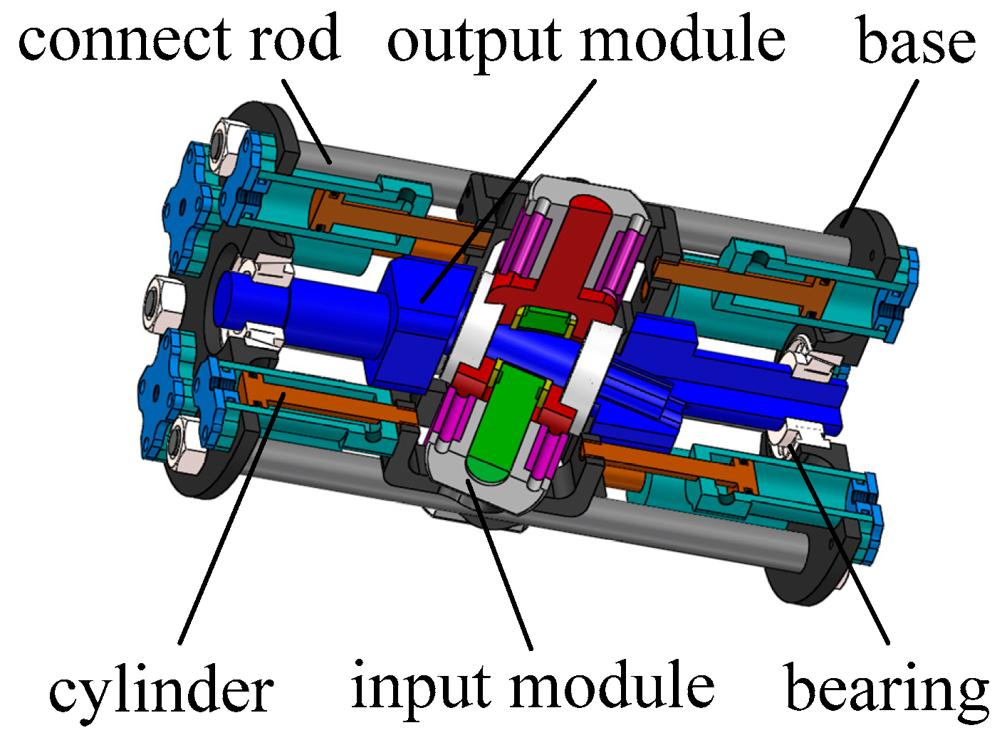
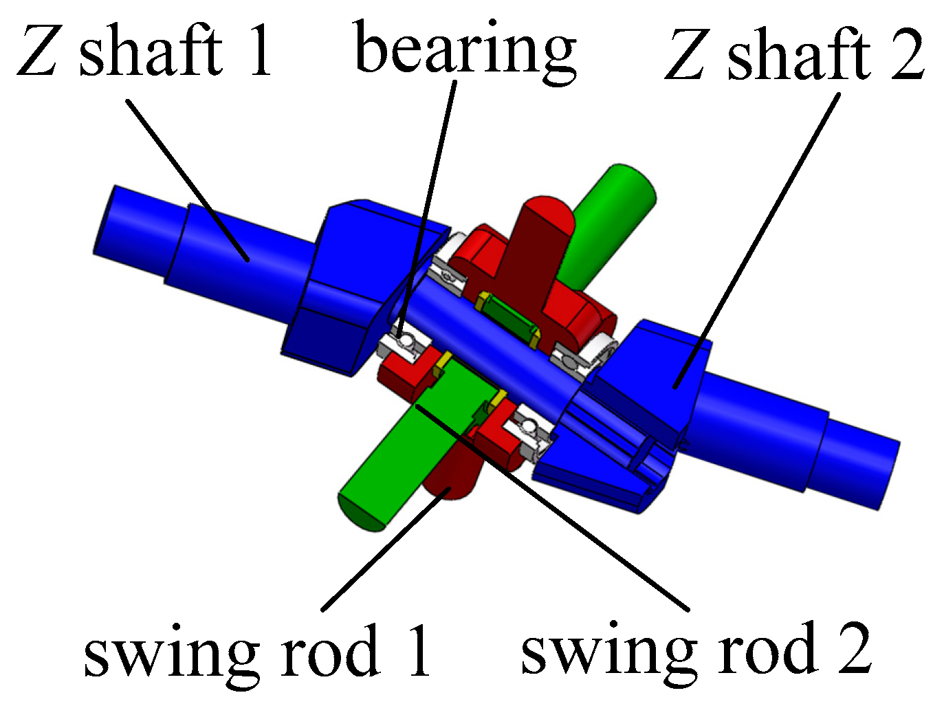
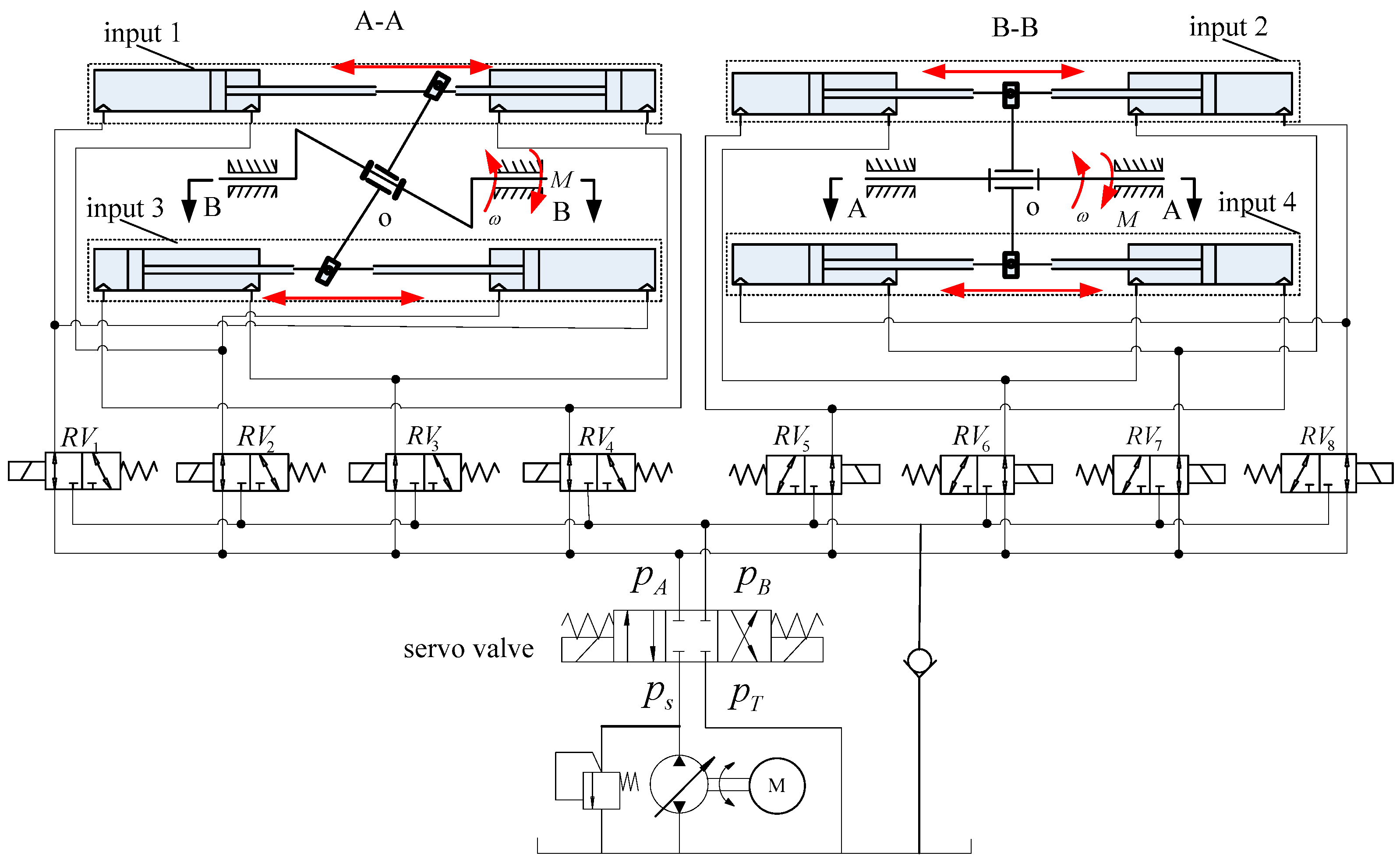
2.2. Structure Description

The novel wobble plate hydraulic joint has a shape of a cylinder with a bottom diameter of 120 mm and a height of 210 mm, and its weight is less than 2 kg. The structure is shown in Figure 4. One input module consists of two symmetrically hydraulic cylinders connected by threads. Four input modules are evenly arranged on the base. The structure of the output module is shown in Figure 5. Z shaft 1 and Z shaft 2 are connected by a spline to form a Z shaped shaft. Swing rod 1 is installed on the Z shaped shaft by an angular contact ball bearing, which forms a revolute pair. With the bearing shell, swing rod 2 is located in the inside of swing rod 1, which forms a wobble plate.
When the piston rod of the input module moves, the swing rod 1 rotates around the intersection of its axis and Z shaped shaft. As swing rod 1 and Z shaped shaft to form a revolute pair, the Z shaped shaft only rotates around the central line of the joint and swing rod 1 rotates relative to its axis. Similarly, swing rod 2 drives the Z shaped shaft to rotate and it rotates relative to its axis. By controlling the thrust and direction of the piston rod, the torque on the Z shaped axis can be generated in different values and directions.
The wobble plate hydraulic joint converts the linear motion of several hydraulic cylinders into rotary motion. The joint supply pressure can be adjusted by connecting different reversing valves with high pressure and low pressure, respectively. In this way, the driving combination of the different hydraulic cylinders can be selected according to the requirement of the load torque, which can realize the match between the output torque and load torque required.
For the joint, the input pressure is equal to the pump output pressure, so Equation (4) is expressed below.
Δ W = p s ( Q s i = 1 n Q i )  
As the output flow from the pump is the sum of all the hydraulic circuits flow.
Q s = i = 1 n Q i  
According to the above analysis, when using the wobble plate joint, the power loss of the power source is zero, which is significant to improve the performance of the mobile robotic manipulator.

3. Analysis of Mechanical Characteristic

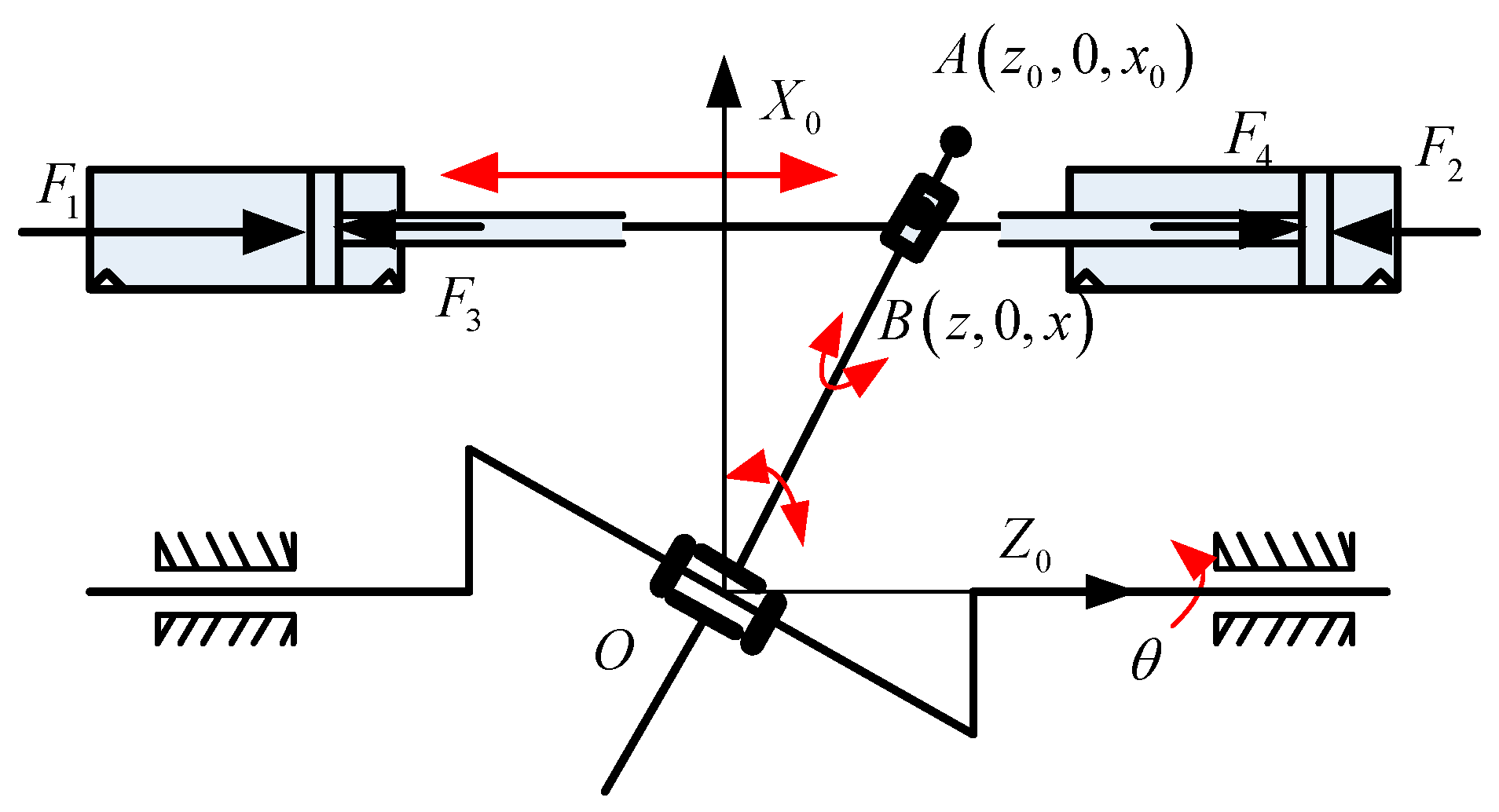
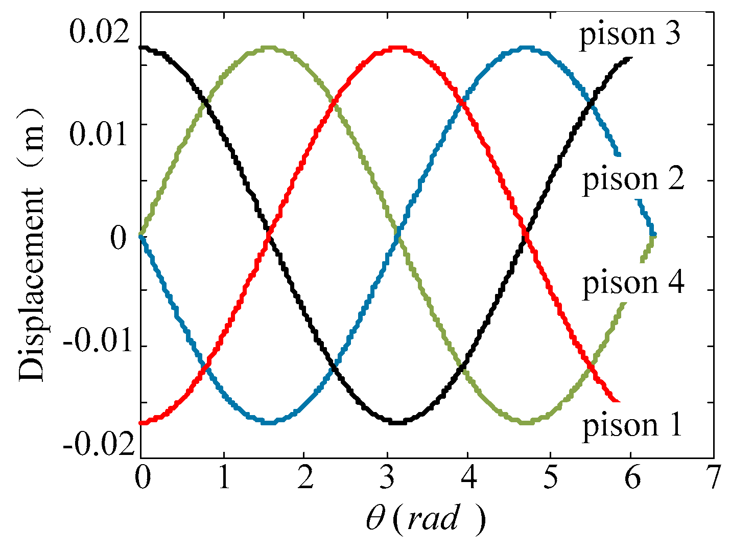
3.1. Kinematic Analysis

Firstly, the joint coordinate systems are established, as shown in Figure 6. As swing rod 1 has a similar motion to swing rod 2, for simplicity, swing rod 2 is selected as the research object.
The intersection point O between the Z shaped shaft and the wobble plate is the origin point of the coordinate system. X 0 Y 0 Z 0 is the inertial coordinate system fixed to the ground, Z 0 and Z shaped output shaft rejoin, the Y 0 axis is perpendicular to the outside of the paper, the initial position of Z shaped output shaft is located in the X 0 Z 0 plane. The Z shaped output shaft can reach the new position by rotating θ in a clockwise direction. X 0 Y 0 Z 0 rotates θ clockwise around the Z 0 axis, reaching the position of the coordinate system X 1 Y 1 Z 1 . X 1 Y 1 Z 1 is the plane coordinate system for the Z shaped shaft, which is the plane formed by output axis and Z shaped shaft. When X 1 Y 1 Z 1 rotates α clockwise around the Y 1 axis, the position of the coordinate system X 2 Y 2 Z 2 is obtained. X 2 Y 2 Z 2 is the rotation coordinate system of the wobble plate, and the Z 2 axis and Z shaped shaft collinear. When X 2 Y 2 Z 2 rotates ϕ anticlockwise around the Z 2 axis, the position of the coordinate system X 3 Y 3 Z 3 is obtained, which is the wobble plate coordinate system. The Z 3 axis overlaps with the Z shaped shaft, and the X 3 axis overlaps with the axis of the plate.
If the position of point A in the coordinate system X 3 Y 3 Z 3 is known, the position of point A in the fixed coordinate system can be calculated, which is represented by a 0 . Where, point A is the end point of the wobble plate, and its position in X 3 Y 3 Z 3 is ( r , 0 , 0 ) , which is represented by a 3 ,
a 0 = R a 3  
where
R = R Z 0 θ R Y 2 α R Z 3 ϕ = [ cos ϕ sin ϕ 0 sin ϕ cos ϕ 0 0 0 1 ] [ cos α 0 sin α 0 1 0 sin α 0 cos α ] [ cos θ sin θ 0 sin θ cos θ 0 0 0 1 ] = [ cos θ cos α cos ϕ + sin θ sin ϕ cos θ cos α sin ϕ + sin θ cos ϕ cos θ sin α sin θ cos α cos ϕ cos θ sin ϕ cos θ cos ϕ + sin θ cos α sin ϕ sin θ sin α sin α cos ϕ sin α sin ϕ cos α ]
When Equation (8) is put into Equation (7), the following formula is obtained.
a 0 = [ x 0 y 0 z 0 ] = r [ cos θ cos α cos ϕ + sin θ sin ϕ sin θ cos α cos ϕ cos θ sin ϕ sin α cos ϕ ]  
Based on the above relations, the kinematic characteristics of the hydraulic joint can be studied. The operating point B of the piston rod and plate shaft is selected, as shown in Figure 7. As the wobble plate and piston rod move together, the piston rod moves along a straight line and the motions of point A and point B are limited in the X 0 Z 0 plane.
In the fixed coordinate system, point A is ( z 0 , 0 , x 0 ) , point B is ( z , 0 , x ) . From the geometric relation, the position equation of point B on the rotation angle is expressed,
z = x z 0 x 0 = x cos ϕ sin α cos θ cos α cos ϕ + sin θ sin ϕ  
where x , α , ϕ are known. From Formula (10), it can be seen that the position of point B is only relevant to θ .

3.2. Dynamic Analysis

Based on the above analysis, the dynamic model of the hydraulic joint is established by the Lagrange Method. To simplify the model, the angle of the output shaft is used as the generalized coordinates.
d d t ( E k e q ˙ r ) E k e q ˙ r + E p e q r = M r  
where E k e is the sum of the kinetic energy of each rigid body. E p e is the sum of the potential energy of each rigid body. q r is the generalized coordinate, M r is the generalized force. As the joint is symmetric around the origin point, O, the potential energy of the mechanism is zero.
(1) The kinetic energy of the wobble plate
The motion of the wobble plate is a superposition of rotation around the Y 0 axis and the rotation around the wobble plate axis. So the kinetic energy of the wobble plate is expressed below.
E k e i = 1 2 I i Y 0 ω i Y 0 2 + 1 2 I i X 3 ω i X 3 2 ( i = 1 , 2 )  
where, I i Y 0 is the moment of inertia around the Y 0 axis. I i X 3 is the moment of inertia around the X 3 axis. As the two parts of the wobble plate move in the same way, the calculation method of kinetic energy is the same. So the total kinetic energy is E k e 1 + E k e 2 .
(2) The kinetic energy of the piston assembly and output shaft
The piston rod moves in a straight line, so the kinetic energy is 1 2 m v i 2 ( i = 1 , 2 , 3 , 4 ). Where, m is the total mass of the piston assembly, including two pistons, one push rod, and bearings. v i is the velocity of the piston rod i. So the total kinetic energy is i = 1 4 1 2 m v i 2 . The output shaft rotates at an angular velocity of θ ˙ , and its moment of inertia is around the rotating axis is I , so the kinetic energy of the output shaft is 1 2 I θ ˙ 2 .
By combining the above formulas, we get the total kinetic energy of the piston assembly and output shaft.
E k e = i = 1 4 1 2 m v i 2 + E k e 1 + E k e 2 + 1 2 I θ ˙ 2  
F t i is the resultant force of the wobble plate against the pistons.
Fti = F1 + F2 + F3 + F4
where F1, F2, F3, F4 are the fluid pressures on pistons, respectively, and the right side is selected as the positive direction.
The power generated by the external forces is equal to the power generated by the generalized torque, as shown in the following equation.
M r θ ˙ = i = 1 4 F t i v i + M ω  
where, the external torque M acts on the output shaft, ω is the angular velocity of the output shaft. By combining the above formulas, we obtain the output torque.
M = ( d d t ( E k e θ ˙ ) E k e θ i = 1 4 F t i v i θ ˙ ) θ ˙ ω  
Based on mathematical models, the kinematics and dynamics of the wobble plate joint are numerically analyzed. The relevant simulation parameters are shown in Table 1.
To study the characteristics of output torque, the servo valves in operation are fully open. The force acting on the swing rod is made equal by controlling the closing of the switch valves. As all the output of input modules are in the same direction, the output torque of the hydraulic joint at each position is at its maximum value. The Z shaped output shaft of the hydraulic joint rotates at a constant speed, with an angle function of θ = π t / 6 .
Based on a numerical simulation, the displacements of the joint piston are obtained, as shown in Figure 8. The result shows that the motion curve of the input piston rod is a triangle function curve with no impact point. The piston rod acceleration is obtained by differentiating displacement, which shows no abrupt point in the curve and indicates that the piston rod moves smoothly. The joint output torque curve is depicted in Figure 9. It can be seen that the value of the output torque is greater than 380 Nm. The curve contains four peaks, roughly spaced by an angle of π / 2 . The reason is that four piston rods are arranged between π / 2 , therefore, the operating phases between them are different by π / 2 . As the value of the output torque varies, adjusting the servo valve action in advance can provide joint motion stability.

4. Design of Load Matching Control

4.1. Analysis of Control Principle

As shown in Figure 10, eight reversing valves are recorded as R V 1 , R V 2 , R V 3 , R V 4 , R V 5 , R V 6 , R V 7 and R V 8 , the control signal is X = [ x 1 x 2 x 3 x 4 x 5 x 6 x 7 x 8 ] . When x i = 1   ( i = 1 , 2 , , 8 ) , the channel of the reversing valve connects to port A on the servo valve, when x i = 0   ( i = 1 , 2 , , 8 ) , the channel of the reversing valve connects port B.
Due to the focus on relations between output and switch valves combination, the valve throttle loss and cylinder friction are not considered here. So forces exerted by the input modules on the swing rod are shown as follows, the right is selected as the positive direction.
F 1 = i = 1 4 ( 1 ) i 1 x i p A S i + i = 1 2 ( 1 ) i 1 ( 1 x i ) p B S i  
F 2 = i = 5 8 ( 1 ) i 1 x i p A S i + i = 5 8 ( 1 ) i 1 ( 1 x i ) p B S i  
F 3 = F 1  
F 4 = F 2  
where p A and p B respectively represent the pressure at port A and port B, S is the effective area of the piston in the chamber which is the reversing valve i connecting to.
S i = { π D 2 4 i = 1 , 4 , 5 , 8 π ( D 2 d 2 ) 4 i = 2 , 3 , 6 , 7  
The flows through port A and port B, which are marked as Q A and Q B , respectively, can be calculated. If oil flows out from the port of servo valve, the value is positive.
Q A = 2 i = 1 8 ( 1 ) i 1 x i y ˙ i S i  
Q B = 2 i = 1 8 ( 1 ) i 1 ( 1 x i ) y ˙ i S i  

4.2. Design of the Load Matching Controller

According to the change of load torque, the wobble plate hydraulic joint can select the best position combination of the reversing valves, which can realize the match between the output torque and load torque. Therefore, the load matching controller needs to solve the following problems.
(1)
Determine the combination of the reversing valves, which can output the torque that is closest to the load torque. To meet the requirements of joint angle tracking and ensure sufficient driving force, the output torque selected initially is usually slightly larger than the actual load torque.
(2)
Predict the trend of the angle tracking error and adjust the mode of the valves’ combination. At a sampling point, if the absolute value of joint angle error is less than the allowable value, the existing combination remains unchanged, otherwise, the characteristics of the error need to be further determined. When the error is positive, it indicates that the output torque is insufficient, so it should be increased. When the error is negative, it indicates that the output torque is sufficient, so it should be reduced.
The load matching controller is designed. The results of different valve position combinations are analyzed and the same effects of the position combinations are merged. Eight reversing valves are divided into group A and group B, group A includes R V 1 , R V 2 , R V 3 , R V 4 , whose control signal is [x1, x2, x3, x4]; group B includes R V 5 , R V 6 , R V 7 , R V 8 , whose control signal is [x5, x6, x7, x8]. According to the analysis, when group A and group B send out 9 control signals, the input module exerts different forces shown in Table 2. Where, K is defined as regulating grade, whose value goes from small to large, corresponding to the nine outputs.
The specific load matching control process is designed as follows.
Step 1:
Use the torque sensor to measure the load torque τ .
Step 2:
Calculate all the output torques at the current rotating angle according to all the reversing valve position combinations.
Step 3:
Calculate all the generalized torques, which would be sorted from small to large, to form a sequence of generalized torques with the number of regulating grade N c .
Step 4:
In the generalized torque series, select the optimal generalized torque which is closest to the last torque and the initial grade is selected.
Step 5:
Compare the angle tracking error e with the allowable value δ 11 . If | e | < δ 11 , it indicates that the optimal generalized torque selected is appropriate, and grade K is maintained; otherwise, Step 6 is performed.
Step 6:
Compare the derivative e of the angle tracking error with the corresponding allowable value δ 2 .
When e > δ 11 , if e δ 2 , it indicates that the output torque is insufficient and grade K should be increased by Δ K , if e < δ 2 , it means that there’s a decrease in the angle tracking error, if e < δ 12 , maintain grade K , otherwise, increase the value of K to increase the output torque.
When e < δ 11 , if e < δ 2 , it indicates that the output torque is too large and grade K should be decreased by Δ K , if e > δ 2 , it means that there is a decrease in the angle tracking error, if e > δ 12 , maintain grade K , otherwise, decrease the value of K to increase the velocity of the error reduction.
Step 7:
The optimal generalized torque is applied to the hydraulic joint and the instant angular displacement is fed back to step 5.
Step 8:
Go back to step 2 and perform the following steps in turn until the ending.
Where, τ is load torque, the generalized torque is expressed as M q = M + τ , K is the regulating grade, which indicates the position of the optimal generalized torque in sequence. Δ K is the step size of the grade regulating. N c is the total number of regulating grade. e is angle tracking error. e is the derivative of the angle tracking error. δ 11 and δ 12 are the allowable values of error, δ 2 is the allowable velocity value of error reduction.

5. Simulation and Discussion

As the long development period of wobble plate hydraulic joint, the energy saving effect of the novel joint is verified by simulation. Combined with the strategy of the load matching control, the servo control system is constructed as shown in Figure 11.
In Figure 11, θ d is the input angle. θ a c t is the output angle. K p , K i and K d are parameters of the proportionality coefficient, integral coefficient, and differential coefficient, respectively, x is the control signal for reversing valves.
The control system is composed of two closed loops, an angular control loop, and the load matching control loop. The angle control closed loop is the main one and detailed process is stated as follows.
Compare the expected angle θ d with the actual angle θ a c t . The angular error e is regarded as the input signal of the PID controller and the output signal of PID controller is served as the control signal of the servo valve, which is used to change the opening size of the servo valve. At the same time, the angle is controlled, the load torque of the hydraulic joint changes in real time. The function of the load matching control is to select the most suitable position combination of reversing valves, so that the output torque matches the load torque, which can reduce energy loss on the servo valve.
According to the control system shown in Figure 11, the simulation models are built based on MATLAB R2014a. In load matching control simulation, relevant parameters are shown in Table 3.
In verification, the joint expected angle curve is set as θ = π cos ( t ) + π , the load torque is set as τ = 200 sin ( t ) , the simulation results are shown in Figure 12 and Figure 13.
Figure 12 shows the output torque tracking for the load torque. The dotted black line represents the varying load torque, the solid red line represents the output torque provided by the hydraulic joint. Figure 13 shows the difference between the output torque and the load torque. It can be seen that output torque from the novel hydraulic joint can be adjusted according to the change of the load torque, and the difference between the output torque and load torque is within the allowable range. The above result indicates that the wobble plate hydraulic joint can match the output torque and load torque by regulating the connection between different input modules and high-pressure supply.
Figure 14 shows the energy curves of different hydraulic joints with variable load torques. As can be seen from the figure, the energy consumption of the wobble plate hydraulic joint is much lower than that of traditional hydraulic joint, and the dotted line represents the energy saved by the novel joint. Based on numerical calculation, the energy consumption of traditional hydraulic joints is 9606 J, and that of wobble plate hydraulic joints is 3492 J. As both hydraulic joints perform the same action, which means the same energy required E d i , it is obvious that the energy efficiency η E in the wobble plate joint is higher than the traditional one.
To study the influence of the regulating grade step size on the angle tracking error and energy loss, different step sizes (such as Δ K = 1 , Δ K = 2 and Δ K = 3 ) are selected for the simulation test. Figure 15 shows the angle tracking error corresponding to different step sizes. As the figure shows, when Δ K = 1 , the joint has the largest tracking error. The tracking error of Δ K = 2 and Δ K = 3 are not much different, the error of Δ K = 3 seems a little smaller.
The curves of the energy consumption corresponding to different step sizes are shown in Figure 16. It can be seen from the figure that the energy consumption changes very little with different step sizes. In general, the lower the grade is, the lesser the energy the hydraulic joint consumes.
Based on the simulation, it was proven that the wobble plate hydraulic joint can change the output torque according to the change of load torque, which ensures that the output torque matches load torque. At the same time, the test results show that the increase of the step size can improve the accuracy of angle tracking, while, it reduces joint energy efficiency. Therefore, on the basis of the precision requirement of angle tracking, a smaller step size Δ K should be selected, which is especially helpful to improve the energy efficiency of the wobble plate joint.

6. Conclusions

This paper presents a novel wobble plate hydraulic joint with a small size, lightweight, large load capacity, and high energy efficiency. The following conclusions are drawn.
(1)
Based on an efficiency analysis of the traditional hydraulic system in the mobile robotic manipulator, an energy-efficient hydraulic joint with wobble plate structure was proposed. By analyzing its working principle, the reason for the high efficiency in the novel joint was explained.
(2)
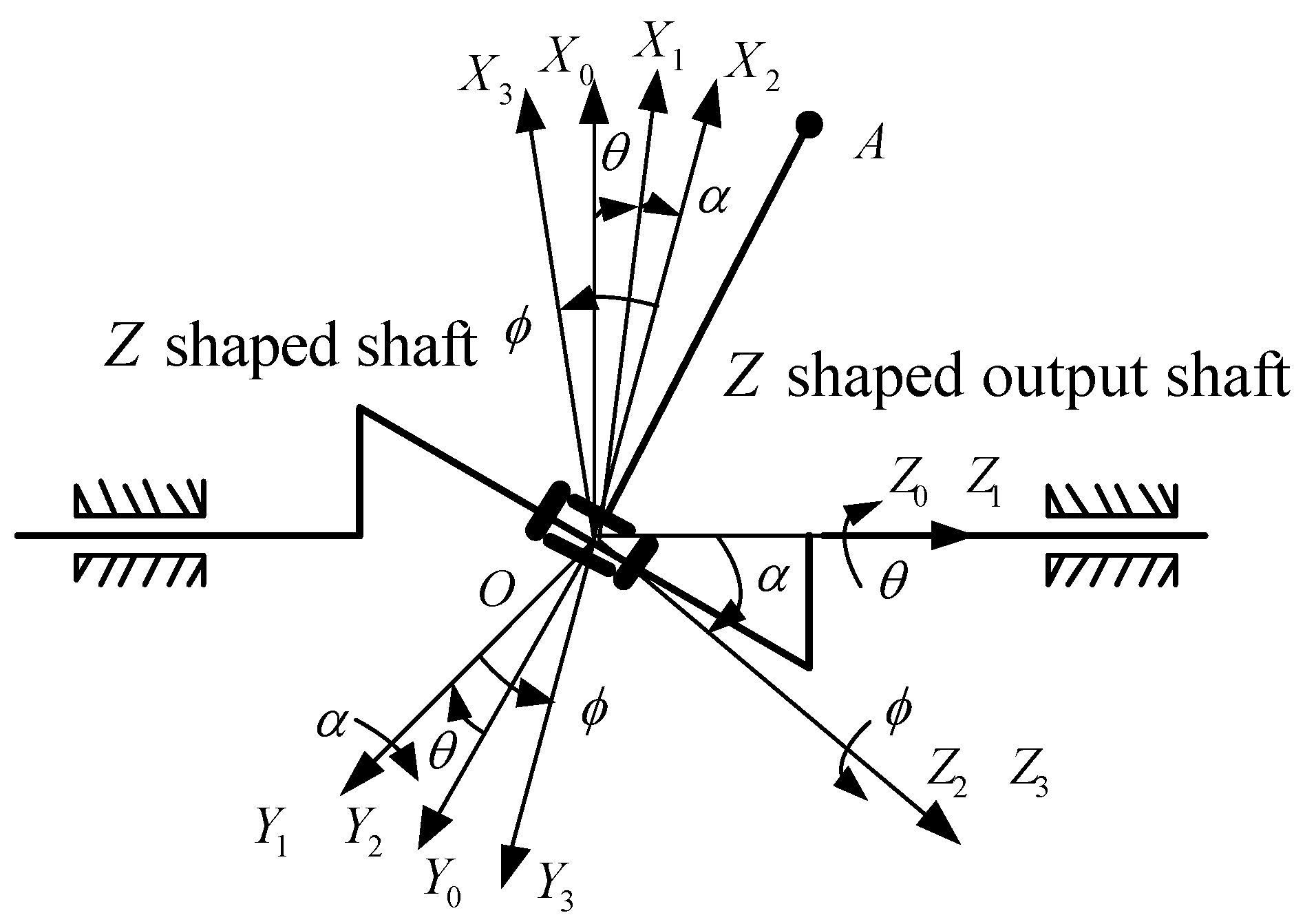
With the method of coordinate transformation, a kinematics model was established. By using the Lagrange Method, a dynamic model was established. Based on a numerical simulation, the functional relationship between the input angle and output torque of the novel joint was deduced.
(3)
Based on the structural characteristics and control principle, the load matching controller of the wobble plate hydraulic joint was designed, and the specific control processes were formulated.
(4)
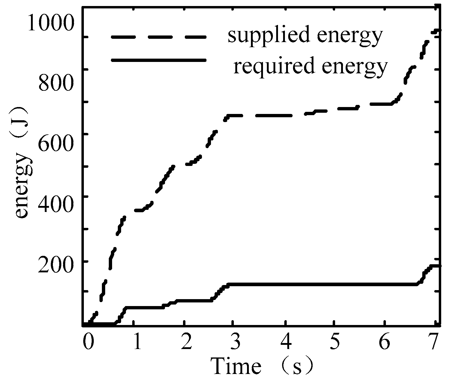
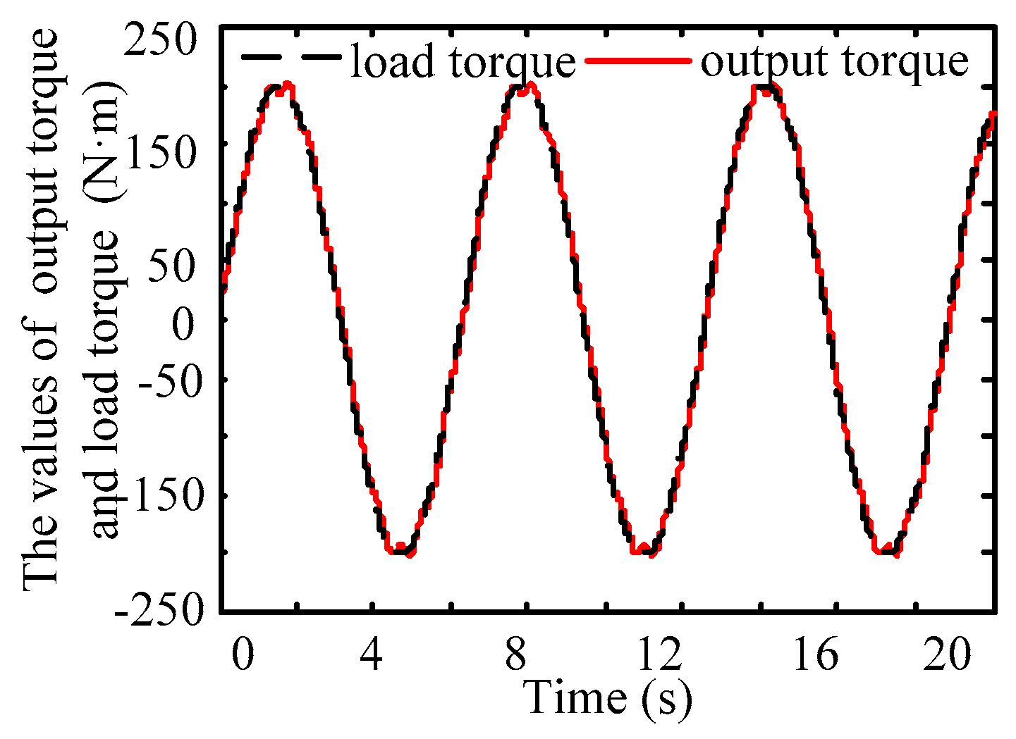
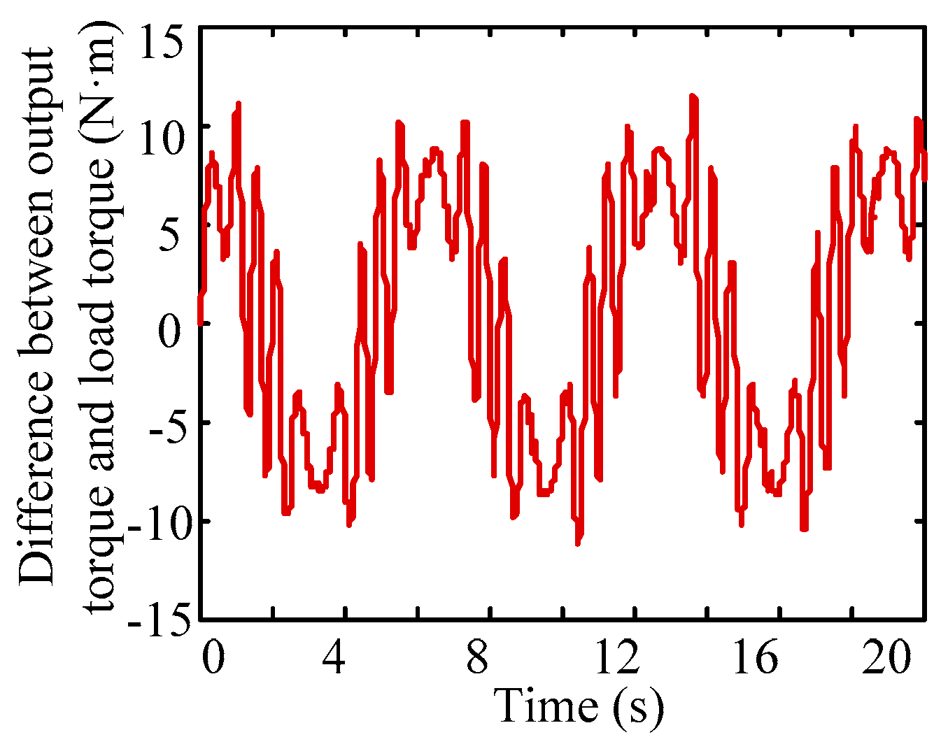
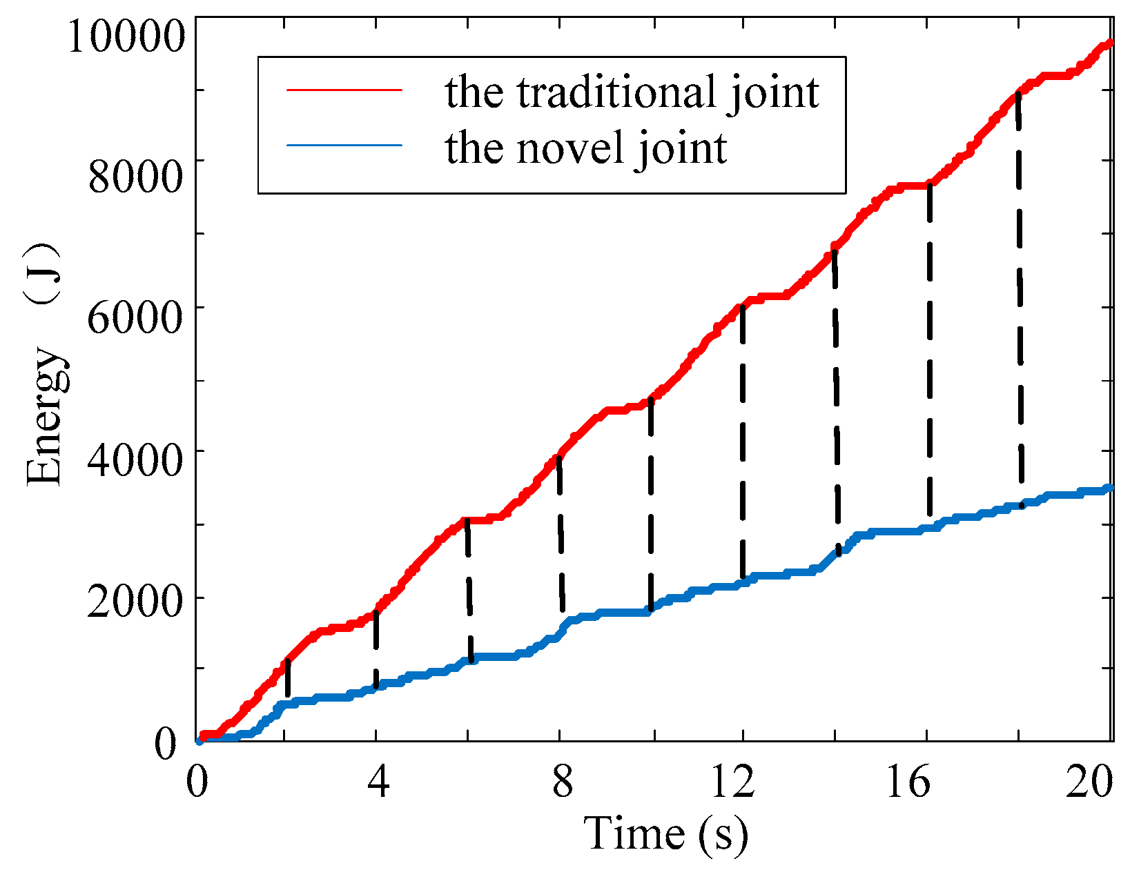
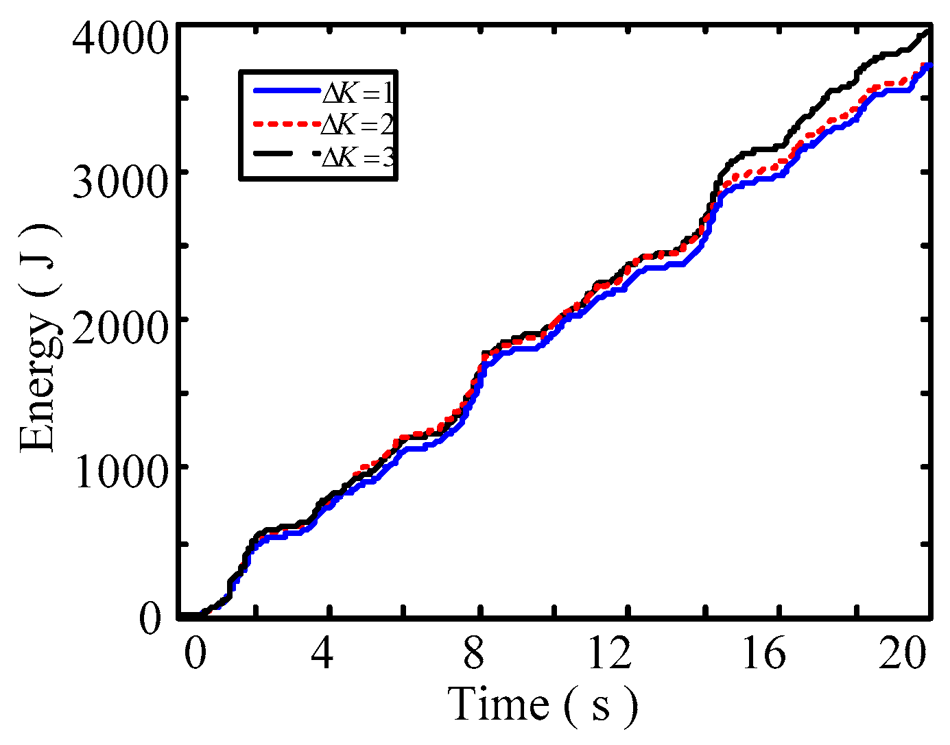
Combined with the strategy of load matching control, the servo control system was established, and simulation was carried out to verify the energy-saving effect of the novel wobble plate hydraulic joint.

Author Contributions

D.F. was responsible for conceiving the study design, performing mathematical modeling and writing most of the manuscript. J.Y. proposed the concept of wobble plate hydraulic joint and participated in the structure design and analysis. J.S. was responsible for guidance, suggestions and manuscript review. Z.W. and Y.F. made contributions to load matching control simulation and helped with editing the manuscript.

Funding

The work reported in this paper was supported by the National Natural Science Foundation of China (51675522).

Conflicts of Interest

The authors declare no conflict of interest.

References

  1. Florek-JasińSka, M.; WimböCk, T.; Ott, C. Humanoid compliant whole arm dexterous manipulation: Control design and experiments. IEEE Trans. Robot. Autom. 2014, 1616–1621. [Google Scholar] [CrossRef]
  2. Zhang, C.Y.; Bai, G.C. Extremum response surface method of reliability analysis on two-link flexible robot manipulator. J. Cent. South Univ. 2012, 19, 101–107. [Google Scholar] [CrossRef]
  3. Marca, R.; Rucińskia, M.; Coatesa, A.; Allouisa, E.; Garlanda, M.; Lachata, D.; Doncheva, A.; Tubbyb, W.; Hamptonb, J.; Kisdib, Á.; et al. Design Concepts and Implementation of the Lightweight Advanced Robotic Arm Demonstrator (LARAD). In Proceedings of the 67th International Astronautical Congress (IAC), Guadalajara, Mexico, 26–30 September 2016. [Google Scholar]
  4. Feng, F.; Liu, Y.; Liu, H.; Cai, H. Design Schemes and Comparison Research of the End-effector of Large Space Manipulator. Chin. J. Mech. Eng. 2012, 25, 674–687. [Google Scholar] [CrossRef]
  5. Li, Y.; Hou, J.; Yuan, J.; Zhao, X.; Liu, X.; Zhang, L. Experiment and vibration suppression algorithm for high-branch pruning manipulator based on fuzzy PID with improved PSO. Trans. Chin. Soc. Agric. Eng. 2017, 33, 49–58. [Google Scholar]
  6. Albu-Schäffer, A.; Haddadin, S.; Ott, C.; Stemmer, A.; Wimböck, T.; Hirzinger, G. The DLR lightweight robot: Design and control concepts for robots in human environments. Ind. Robot 2007, 34, 376–385. [Google Scholar] [CrossRef]
  7. Zoss, A.B.; Kazerooni, H.; Chu, A. Biomechanical Design of the Berkeley Lower Extremity Exoskeleton (BLEEX). IEEE/ASME Trans. Mechatron. 2006, 11, 128–138. [Google Scholar] [CrossRef]
  8. Albers, A.; Ottnad, J. Integrated Structural and Controller Optimization in Dynamic Mechatronic Systems. J. Mech. Des. 2010, 132, 041008. [Google Scholar] [CrossRef]
  9. Shumei, Y.U. Development of an Amphibious Snake-like Robot and Its Gaits on Ground and in Water. J. Mech. Eng. 2012, 48, 18–25. [Google Scholar]
  10. Lin, J.; Jie, Z.; Wenchao, W.; Xianbao, X.; Xinyuan, C.; Hui, Z.; Liangcai, Z. Easy control hydraulic rotary self-servo reconfigurable decoupling hydraulic joint. In Proceedings of the International Conference on Mechatronics and Automation, Chengdu, China, 5–8 August 2012; pp. 2361–2365. [Google Scholar]
  11. Niguchi, N.; Hirata, K. Magnetic-geared motors with high transmission torque density. COMPEL Int. J. Comput. Math. Electr. Electron. Eng. 2015, 34, 428–438. [Google Scholar] [CrossRef]
  12. Huang, S.N.; Tan, K.K.; Lee, T.H. Adaptive friction compensation using neural network approximations. IEEE Trans. Syst. Man Cybern. Part C 2000, 30, 551–557. [Google Scholar] [CrossRef]
  13. Tan, K.K.; Huang, S.N.; Jiang, X. Adaptive control of ram velocity for the injection moulding machine. IEEE Trans. Control Syst. Technol. 2001, 9, 663–671. [Google Scholar] [CrossRef]
  14. Seok, S.; Wang, A.; Otten, D.; Kim, S. Actuator design for high force proprioceptive control in fast legged locomotion. In Proceedings of the IEEE/RSJ International Conference on Intelligent Robots and Systems, Vilamoura, Portugal, 7–12 October 2012; pp. 1970–1975. [Google Scholar]
  15. Liyanage, M.H.; Krouglicof, N.; Gosine, R. Design and control of a high performance SCARA type robotic arm with rotary hydraulic actuators. In Proceedings of the Canadian Conference on Electrical and Computer Engineering (CCECE 2009), St. John’s, NL, Canada, 3–6 May 2009; pp. 827–832. [Google Scholar]
  16. Liang, X.C.; Wang, G.J.; Zheng, X.G. Research on Rotary Actuator Based on Screw Device. Acta Aeronautica et Astronautica Sinica 2003, 24, 282–285. [Google Scholar]
  17. Deng, M.J.; Wang, Z.; He, H.H.; Xue, Y. Design and Weight Lifting Analysis of a Strengthen Upper Limb Exoskeleton Robot. Appl. Mech. Mater. 2013, 437, 695–699. [Google Scholar] [CrossRef]
  18. Bhounsule, P.A.; Cortell, J.; Ruina, A. Design and control of ranger: An energy-efficient, dynamic walking robot. In Proceedings of the Fifteenth International Conference on Climbing and Walking Robots and the Support Technologies for Mobile Machines (CLAWAR 2012), Baltimore, MD, USA, 23–26 July 2012; pp. 441–448. [Google Scholar]
  19. Seok, S.; Wang, A.; Chuah, M.Y.; Otten, D.; Lang, J.; Kim, S. Design principles for highly efficient quadrupeds and implementation on the MIT Cheetah robot. In Proceedings of the IEEE International Conference on Robotics and Automation, Karlsruhe, Germany, 6–10 May 2013; pp. 3307–3312. [Google Scholar]
  20. Ho, T.H.; Ahn, K.K. Design and control of a closed-loop hydraulic energy-regenerative system. Autom. Constr. 2012, 22, 444–458. [Google Scholar] [CrossRef]
  21. Ho, T.H.; Ahn, K.K. Modeling and simulation of hydrostatic transmission system with energy regeneration using hydraulic accumulator. J. Mech. Sci. Technol. 2010, 24, 1163–1175. [Google Scholar] [CrossRef]
  22. Du, C.; Plummer, A.R.; Johnston, D.N. Performance analysis of an energy-efficient variable supply pressure electro-hydraulic motion control system. Control Eng. Pract. 2016, 48, 10–21. [Google Scholar] [CrossRef]
  23. Zimmerman, J.; Ivantysynova, M. Hybrid displacement controlled multi actuator hydraulic systems. In Proceedings of the Twelfth Scandinavian International Conference on Fluid Power (SICFP11), Tampere, Finland, 18–20 May 2011. [Google Scholar]
  24. Hippalgaonkar, R.; Ivantysynova, M. A Series-Parallel Hydraulic Hybrid Mini-Excavator with Displacement Controlled Actuators. In Proceedings of the 13th Scandinavian International Conference on Fluid Power (SICFP2013), Linköping, Sweden, 3–5 June 2013. [Google Scholar]
  25. Daher, N.; Ivantysynova, M. Energy analysis of an original steering technology that saves fuel and boosts efficiency. Energy Convers. Manag. 2014, 86, 1059–1068. [Google Scholar] [CrossRef]
Figure 1. The schematic diagram of the multi-joint vehicle manipulator.
Energies 11 02915 g001
Figure 2. The energy curves of a hydraulic joint on the mobile manipulator.
Energies 11 02915 g002
Figure 3. The diagram of the mobile manipulator hydraulic system.
Energies 11 02915 g003
Figure 4. The structure diagram of the wobble plate joint.
Energies 11 02915 g004
Figure 5. The structure diagram of the output module.
Energies 11 02915 g005
Figure 6. The coordinate systems of the wobble plate joint.
Energies 11 02915 g006
Figure 7. The kinematic diagram of the wobble plate joint.
Energies 11 02915 g007
Figure 8. The displacements of different piston rods.
Energies 11 02915 g008
Figure 9. The curve of the wobble plate joint output torque.
Energies 11 02915 g009
Figure 10. The diagram of the hydraulic system in the wobble plate joint.
Energies 11 02915 g010
Figure 11. Diagram of a hydraulic joint control system.
Energies 11 02915 g011
Figure 12. The curves of the load torque and output torque.
Energies 11 02915 g012
Figure 13. The curve of the load torque matching difference.
Energies 11 02915 g013
Figure 14. The energy curves of the novel joint and the traditional one.
Energies 11 02915 g014
Figure 15. The curves of angle tracking error for different step sizes.
Energies 11 02915 g015
Figure 16. The curves of energy consumption for different step sizes.
Energies 11 02915 g016
Table 1. The structural parameters of the wobble plate joint in the simulation.
ParameterSymbolValue
piston diameter (mm)D18
rod diameter (mm)d8
length of Z shaped shaft (mm)H48
arrangement diameter of input module (mm)R10
bulge diameter of Z shaped shaft (mm)r40
mass of piston rods (kg) m 0.25
moment of inertia of Y 0 axis (kg·mm2) I i Y 0 420
moment of inertia of X 3 axis (kg·mm2) I i X 3 161
moment of inertia of the output shaft (kg·mm2) I 965
Table 2. The control signal combinations for the reversing valve.
Serial NumberControl Signals [x1 x2 x3 x4]Serial NumberControl Signals [x5 x6 x7 x8]
1[0 0 0 0]1[0 0 0 0]
2[1 0 0 0]2[1 0 0 0]
3[0 1 0 0]3[0 1 0 0]
4[0 0 1 0]4[0 0 1 0]
5[0 0 0 1]5[0 0 0 1]
6[1 1 0 0]6[1 1 0 0]
7[1 0 1 0]7[1 0 1 0]
8[0 1 0 1]8[0 1 0 1]
9[0 0 1 1]9[0 0 1 1]
Table 3. The parameter of a hydraulic joint in the control simulation.
ParametersSymbolValue
proportionality coefficientKp0.086
integration coefficientKi0.02
differential coefficientKd0.02
frequency of reversing valve (Hz)f100
allowable value of error 1 (rad)δ110.002
allowable value of error 2 (rad)δ120.001
allowable velocity value of error (rad/s)δ20.8
step size of grade adjustment Δ K 2

