Article

Linear Hybrid Reluctance Motor with High Density Force

by
Jordi Garcia-Amorós
Departament d’Enginyeria Electrònica, Elèctric i Automàtica, Universitat Rovira i Virgili, 43007 Tarragona, Spain
Energies 2018, 11(10), 2805; https://doi.org/10.3390/en11102805
Submission received: 20 September 2018 / Revised: 10 October 2018 / Accepted: 16 October 2018 / Published: 18 October 2018
(This article belongs to the Section F: Electrical Engineering)

Abstract

:
Linear switched reluctance motors are a focus of study for many applications because of their simple and sturdy electromagnetic structure, despite their lower thrust force density when compared with linear permanent magnet synchronous motors. This study presents a novel linear switched reluctance structure enhanced by the use of permanent magnets. The proposed structure preserves the main advantages of the reluctance machines, that is, mechanical and thermal robustness, fault tolerant, and easy assembly in spite of the permanent magnets. The linear hybrid reluctance motor is analyzed by finite element analysis and the results are validated by experimental results. The main findings show a significant increase in the thrust force when compared with the former reluctance structure, with a low detent force.

1. Introduction

Currently, there are many applications that use hydraulic or pneumatic drives that are being substituted by linear electric actuators in manufacturing industries and robotic systems because of their more stable, precise, and controllable force, along with a higher energy efficiency [1]. In this context, reluctance machines present good environmental behavior due to their high efficiency and inherent ease of assembly and dismantling [2]. For these reasons, among others, there are several studies that have focused on new magnetic structures [3,4,5], in order to enhance their force performance [6] and increase force density by adding permanent magnets [7,8,9,10,11,12,13,14]. As an example, linear switched reluctance motors (LSRM) and linear permanent magnet synchronous motors (LPMSMs) have been proposed for propelling a ropeless elevator [15,16], for an automotive suspension system [17], and for a linear generator in direct drive wave-power converter [18]. Up to now, LPMSMs have a higher power density and efficiency when compared with LSRMs, despite their inherent detent or cogging force, which can be reduced or eliminated by applying several techniques [19,20]. Many current research papers deal with developing and optimizing linear motors in order to increase power density and efficiency [21,22,23].
With this aim, this work presents and analyzes a four-phase LSRM, whose novelty is in the mover. A series of vertically magnetized permanent magnets (PMs) are inserted into the slots of the mover of the LSRM. The resulting actuator is analyzed by finite element analysis (FEA) and a prototype was built and tested. The FEA results and the experimental results are in good agreement and reveal an approximately 100% increase in the peak thrust force; a moderate ripple factor operating in single pulse; and a relative low detent force, about 10% of peak thrust force. The results obtained anticipate an interesting actuator for high force density applications, such as those cited above.

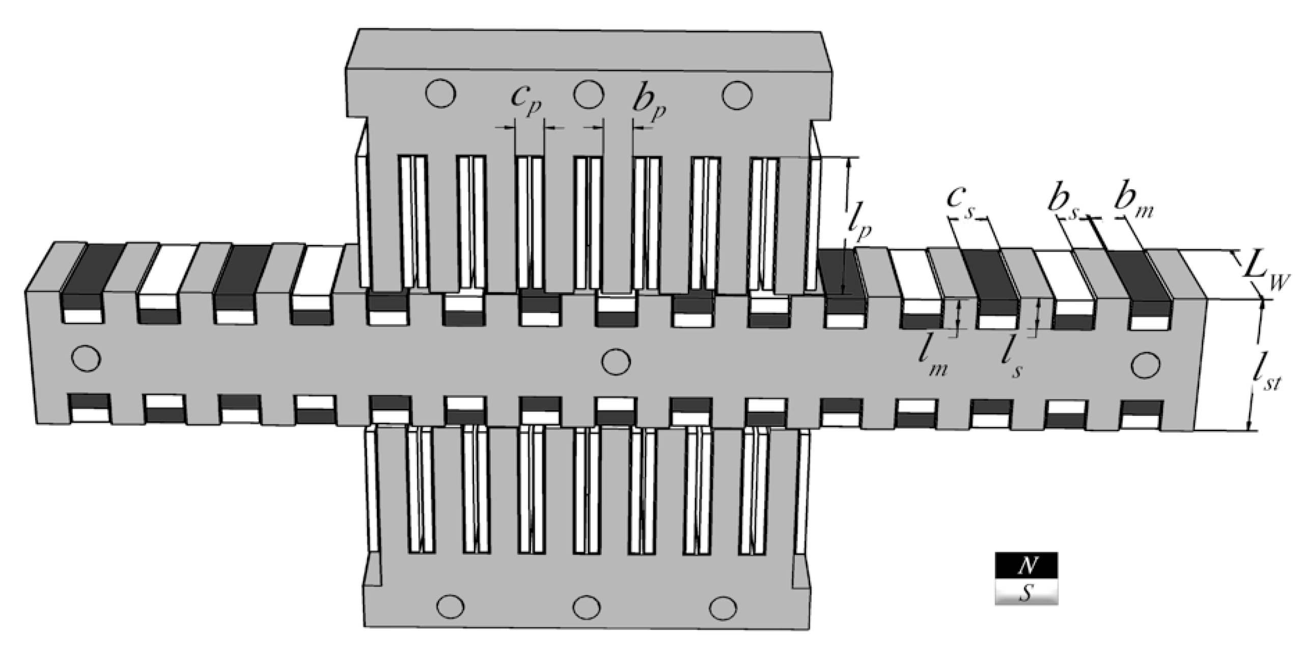
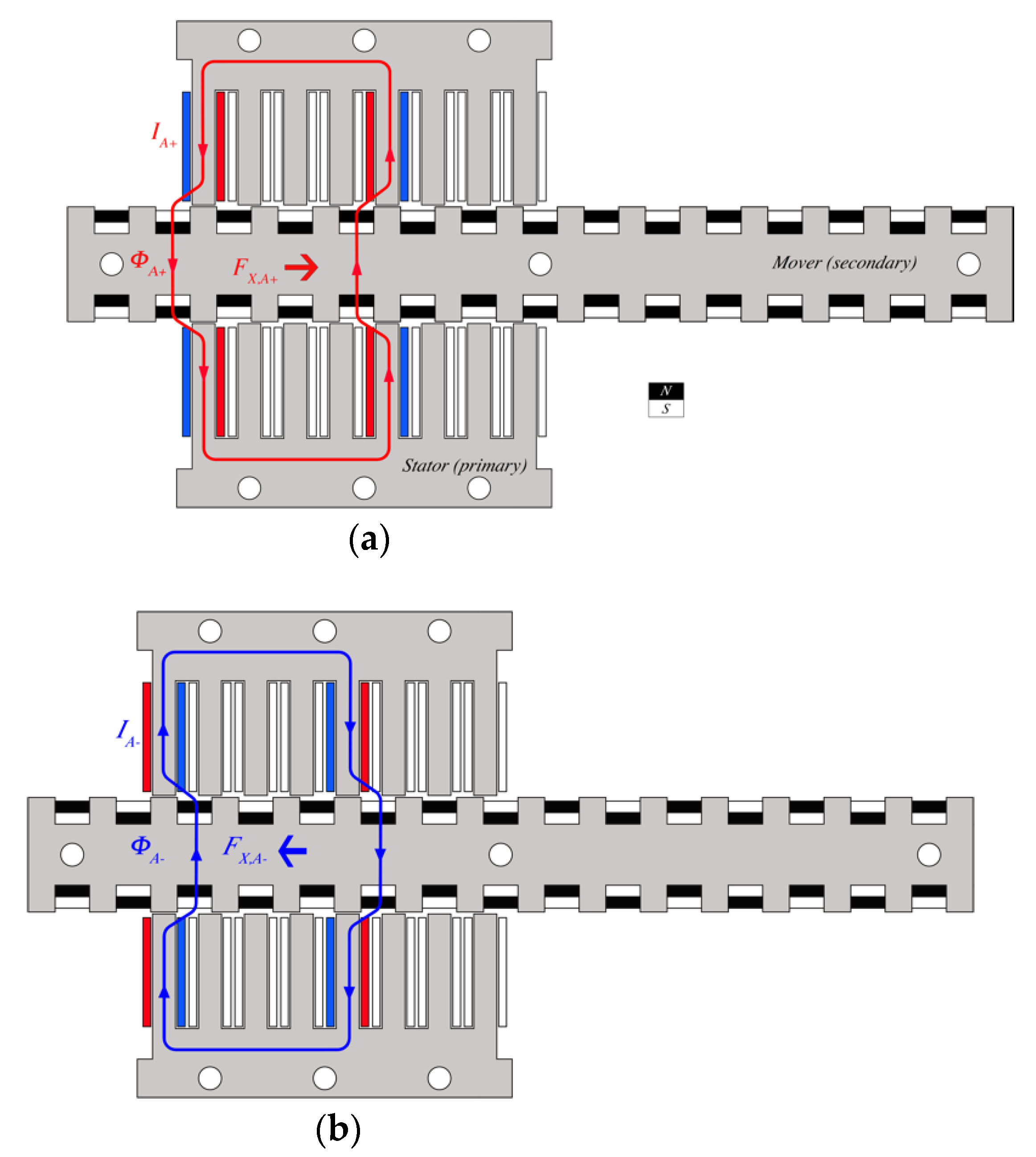
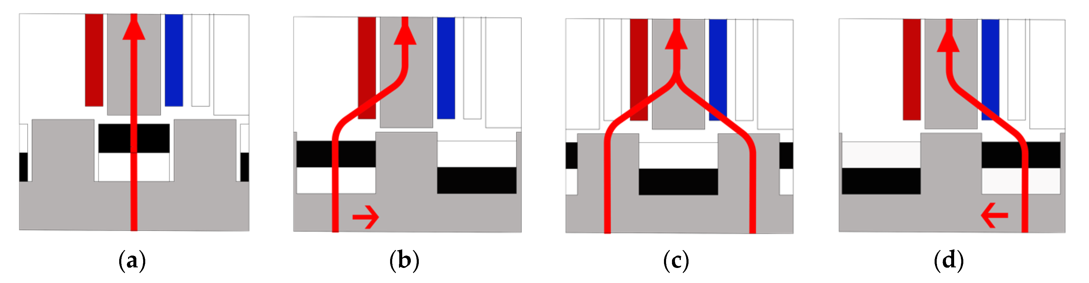
2. Linear Hybrid Reluctance Motor Structure and Operation Principle

LSRMs are classified according to the relation between the planes that contain the flux lines and the axis of movement. Longitudinal flux LSRM is when these planes are parallel, and transverse flux LSRM is when they are perpendicular. Longitudinal flux LSRM may be tubular or flat, with single or double side for the flat case. The LSRM has two main parts: the active part, which contains the concentrated windings, also called primary part; and the passive or secondary part, made of an empty slotted iron structure. This work focuses on the double-sided longitudinal flux LSRM, referred to from now on as LSRM.
The proposed structure is shown in Figure 1. The iron lamination structure is the same as that of a conventional four-phase double-sided longitudinal flux LSRM (see Figure 1 in grey), the modelling, simulation, and test of which are reported in the work of [24]. From this reluctance structure, a series of permanent magnets type NdFeB N32 (in black/white, see Figure 1) have been placed in the secondary slotted lamination. The PMs are vertically magnetized following the arrangement shown in Figure 1. Each phase has four coils per pole connected in series, in such a way that only one flux path is produced. The main dimensions of the primary (active part) are the pole length l p , pole width b p , and slot width c p , the sum of which defines the primary pole pitch τ p = b p + c p . For the secondary (passive) part, the pole dimensions are the length l s , the width b s , the slot width c s , and the mover pole pitch, defined as τ s = b s + c s . The magnet dimensions are the length l m and width b m . The stack lamination width is denoted as L W .
Figure 2 shows the LHRM operating principle in which the four coils of phase A are colored in red and blue, the blue side represents the current entering the paper and the red side is the current flowing out of the paper. The red line of Figure 2a represents the main flux line ( Φ A + ) of phase A at pole-alignment position, when it is fed with a positive current ( I A + ). When phase A current is inverted ( I A ), (see Figure 2b) the blue line represents the main flux line at the same aligned position. In both cases, a significant force appears at pole alignment positions. The force is to the right F X , A + when the current is I A + , and to left F X , A when the current is I A . This phenomenon does not appear in an LSRM, where the force is null at aligned and unaligned pole positions.
The LSRM propulsion force versus position x and current i, ( F ( x , i )) has the same direction (right/left) in the interval x [ 0 , τ S / 2 ] , and for whatever current sign. In the LHRM, the propulsion force is null at the unaligned pole positions, or when the stator poles are aligned with any of the PM poles (N/S) for any current, see Figure 3a,c. The LHRM propulsion force has a positive direction (left to right) in the interval x [ 0 , τ S ] , (see Figure 3b) and a negative direction (right to left) in the interval x [ τ S , 2 · τ S ] (see Figure 3d). This implies a current sign dependency of the LHRM over the propulsion force.
In summary, the LHRM is, similar to the LSRM, a position dependent machine, so an encoder is necessary to operate this actuator, along with an H-bridge inverter, which has to be used instead of the asymmetric bridge converter because of its current sign dependence.

3. Mathematical Model Equations

The presence of the PM allows one to split the total phase flux linkage ( ψ ) as the sum of the flux due to the phase-current ( ψ i ) and the PMs flux-linkage ( ψ P M ), as follows:
ψ ( x , i ) = ψ i ( x , i ) + ψ P M ( x , i )
The electrical phase circuit equation is as follows:
d ψ d t = V R · I
where I, V, and R are the phase current, voltage, and resistance, respectively. Expressing the phase-current flux linkage as the product of the phase inductance and the current, that is: ψ i ( i , x ) = L ( i , x ) · I , and combining Equations (1) and (2), it yields the electrical circuit equation of the LHRM given by the following:
d I d t = L 1 ( R + v · d L d x ) · I + L 1 · ( V d ψ P M d t )
In which the mover velocity is denoted as v. The motion equation neglecting friction is given as follows:
F x + F d = M · d v d t + F l
where F x is the electromagnetic force, F d is the detent force, F l is the load, and M is the mover mass. The instantaneous electromagnetic force ( F x ) is computed from the differential change of co-energy respect to position for a given phase current, as follows:
F x = k = 1 m [ x ( 0 I ψ ( x , i k ) · d i k ) ]
where m is the number of phases. This set of Equations (1)–(5) performs the dynamic and static behavior of the LHRM, which can be implemented in MATLAB-Simulink software for their solution as in LSRM.
The apparent power per phase, SVA or volt-ampere requirement per phase, is defined as the product of peak voltage (Vp) and peak current (Ip) multiplied by the number of switching devices per phase (n). From the area of the energy conversion loop (W), the average output power is given as follows:
P o u t = 2 · W τ s · k d · u b
where k d is the magnetic duty cycle factor defined as k d = 2 · x o f f / τ s . The ratio between the power output and the apparent power or W/VA ratio is given by the following:
P o u t S V A = 2 · W n · τ s · k d · V p · I p · u b

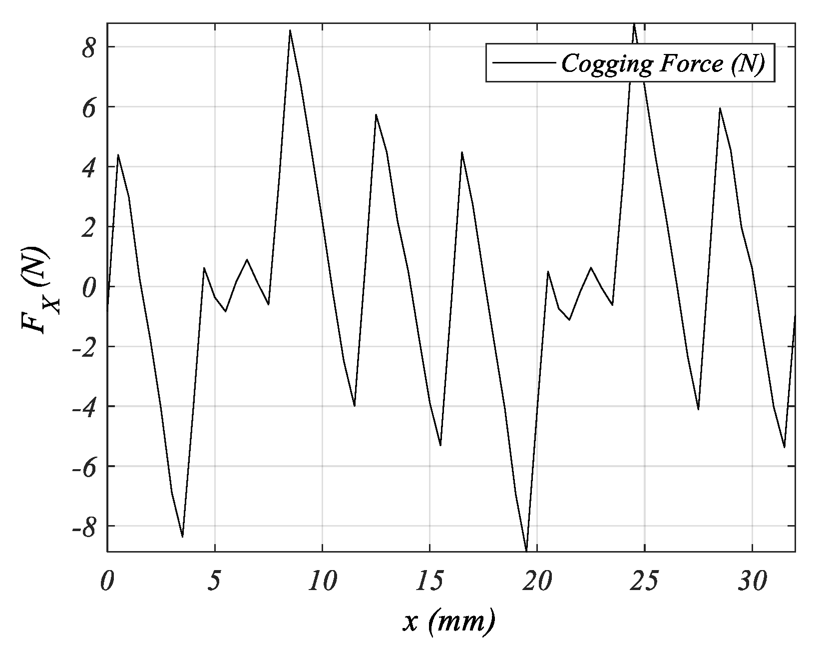
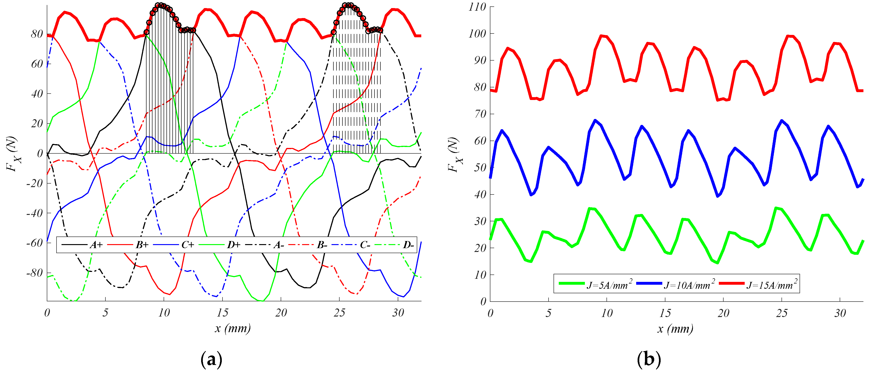
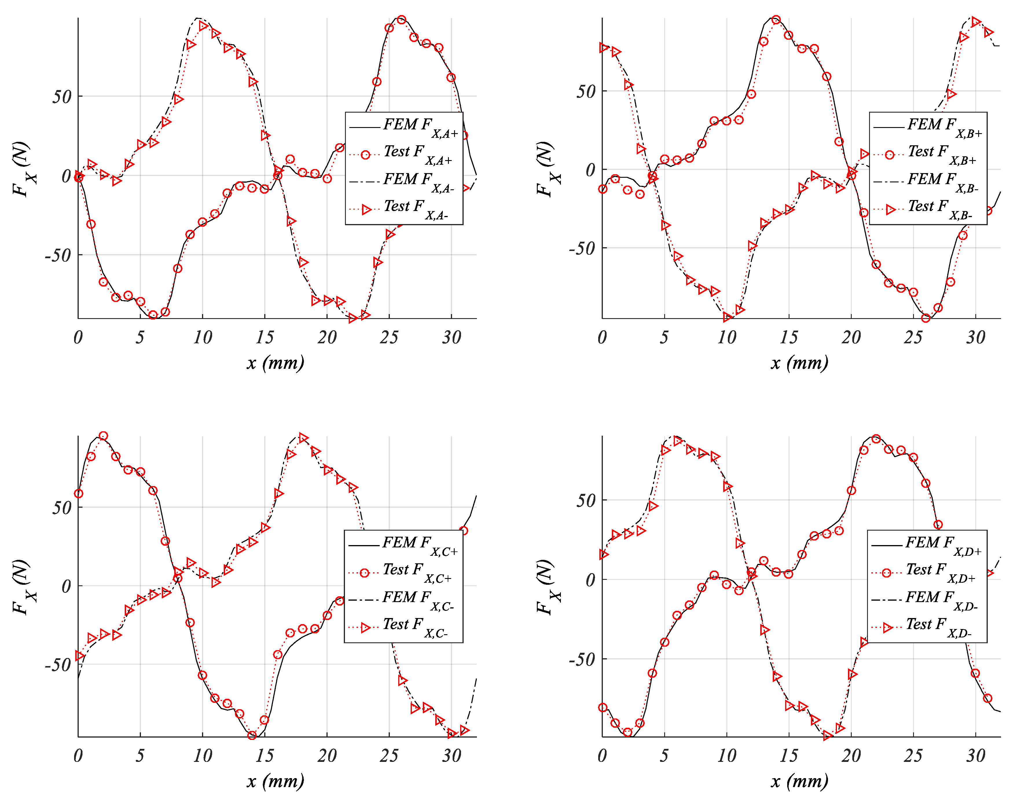
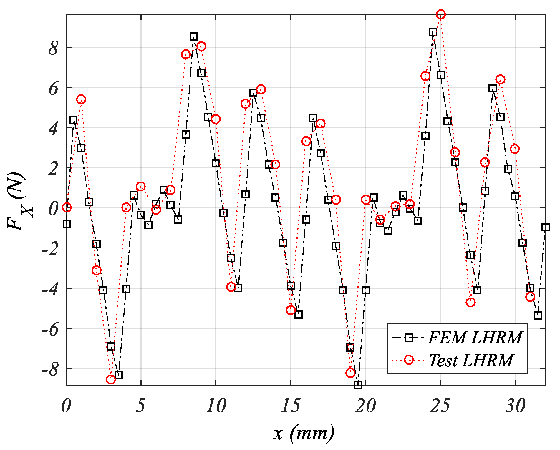
4. Finite Element Analysis Results

The electromagnetic propulsion force is obtained from a 2D-FEM solver [25]. It uses the weighted Maxwell stress tensor technique [26], which is one of the most reliable approaches for force and torque computations [27]. It consists of computing the Maxwell stress tensor over a set of concentric surfaces of thickness δ and contour Γ(δ) wrapping the mover (see Equation (8)), with ny being a normal unit vector in the y-direction; and B x and B y are the magnetic field density in the x and y directions, respectively.
F x = 1 δ 0 δ Γ ( δ ) L W μ 0 · n y · B x · B y · d Γ · d δ
The main dimensions of the FEM model of LHRM shown in Figure 4 are reported in Table A1, see Appendix A. Figure 4 shows the flux lines obtained from the FEA for the zero current excitation phase. This position (see Figure 4) is set as the initial position x = 0 mm, with this position being equivalent to the position shown in Figure 3c, that is, the upper left phase A primary pole is aligned with an S–N magnet.
The electromagnetic force is evaluated for a sequence of even positions in the interval x [ 0 ,   2 · τ s ] and for a set of constant current density values J [ ± 5 , ± 10 , ± 15 ] A/mm2. The LSRM has the same iron laminations and coils, but without magnets.
As can be observed, there are two force profiles for the LHRM (see Figure 5); one for positive current feeding (continuous line, see Figure 5) and one for the negative current (discontinuous line). The LHRM force profiles are substantially higher than in the LSRM. The main FEM comparison results obtained from phase A are summarized in Table 1.
The phase-force profiles are shifted τ s mm when feeding with positive or negative phase current, that is, F X ( x + τ S , I ) = F X ( x , I ) , as can be seen in Figure 5. Table 2 shows the comparison results between phases, when feeding with a positive current density of J = +15 A/mm2 (I = +2.95 A), along with the cogging force values whose force profile is depicted in Figure 6. As is usual in the linear machines, the border phases (i.e., phases A and D) are expected to have slightly different values because of the loss of magnetic symmetry in the borders.
The force profiles shown in Figure 5 are depicted together in Figure 7a. From this figure, an activation phase-sequence for positive (to right, x > 0) or negative movement (to left, x < 0) can be deduced. For obtaining a positive thrust starting from x = 0 mm, the phase-activation sequence must be [B+, C−, D+, A+, B−, C+, D−, A−, B+...], and for a negative thrust, it must be [D−, A−, B+, C−, D+, A+, B−, C+, D−...]. The curve resulting from wrapping the force peaks (see Figure 7a, red thick line) is the total propulsion force when the motor phases are excited following the above-mentioned positive sequence for a flat current waveform and without overlapping phase currents. The optimal conduction interval for phase A is also depicted in Figure 7a, in which for the LHRM dimensions given in Table A1 are [8.75, 12.75 mm] for A+, and [24.75, 28.75 mm] for −A. Figure 7b shows the total propulsion force for positive thrust for the current densities of J [ ± 5 , ± 10 , ± 15 ] A/mm2.
In order to assess the demagnetization of the permanent magnets, the airgap flux density has been drawn in the y-direction, which is the PM-magnetization direction, and then comparing these field distributions with zero current and when exciting phase A.
The PM operating point is defined as the point where the permeance of the magnetic circuit meets the magnet BH characteristic. The irreversible demagnetization occurs when the PM’s flux density decreases under magnet BH-characteristic knee value. For N32 grade, the residual induction is 1.2 T at 20 °C and the knee values are 0.3 T at 60 °C, 0.4 T at 80 °C, 0.5 T at 100 °C, and 0.6 T at 120 °C.
The critical points for phase A are found when the propulsion force reach its peak values, which occurs at mover positions of 6 mm and 28 mm for JA = −15A/mm2, and at mover positions of 10 mm and 22 mm for JA = +15A/mm2 (see Figure 7a). The points analyzed are at mover positions of 22 mm and JA = 15A/mm2, and mover at 28 mm and JA = −15A/mm2 (see Figure 8). The PM critical areas are highlighted (see Figure 8a,b). The By(x,J) distribution field is computed along the airgap red line shown in Figure 8a,b, with the variable x being the position over this line, and J being the current density, whose values are zero in all phases J = 0, and J = J A = ± 15 A/mm2 (see Figure 8c,d in black/red lines, respectively). The results reveal that PM would be demagnetized when operating at JA = 15 A/mm2 at mover position of 22 mm (see Figure 8c), and for magnet temperature exceeding 80 °C.

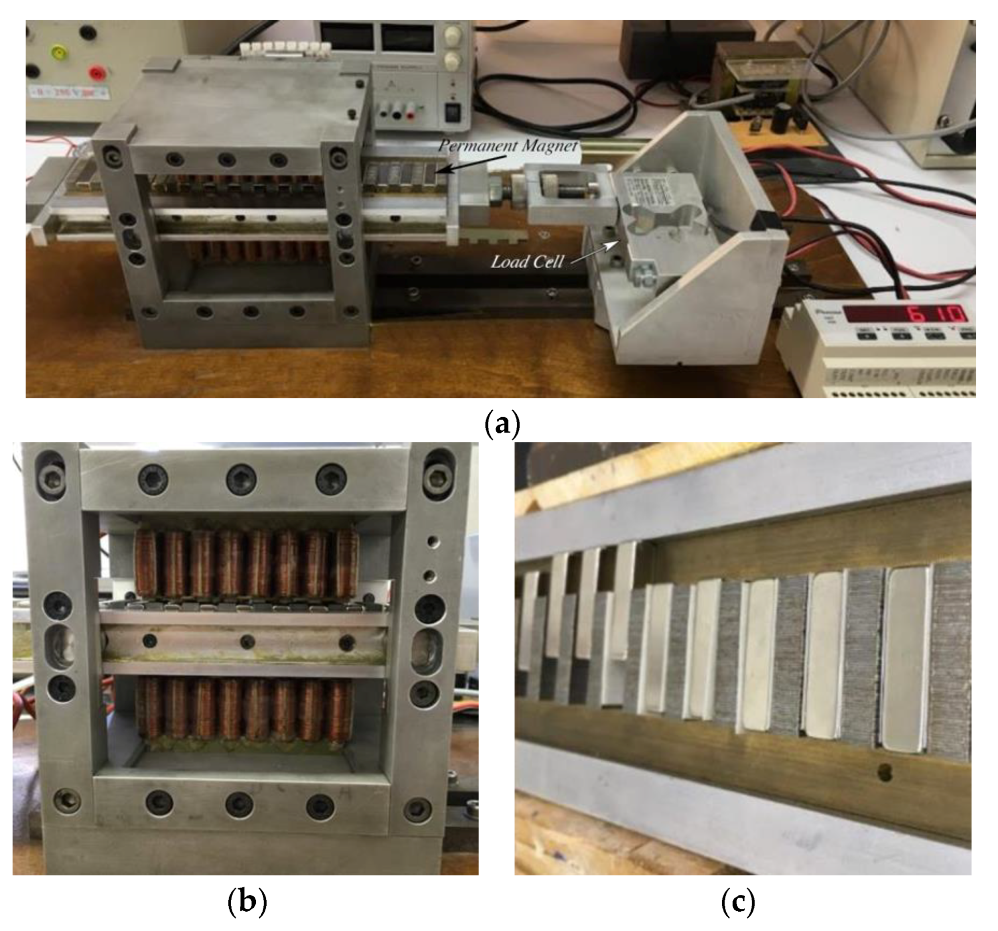
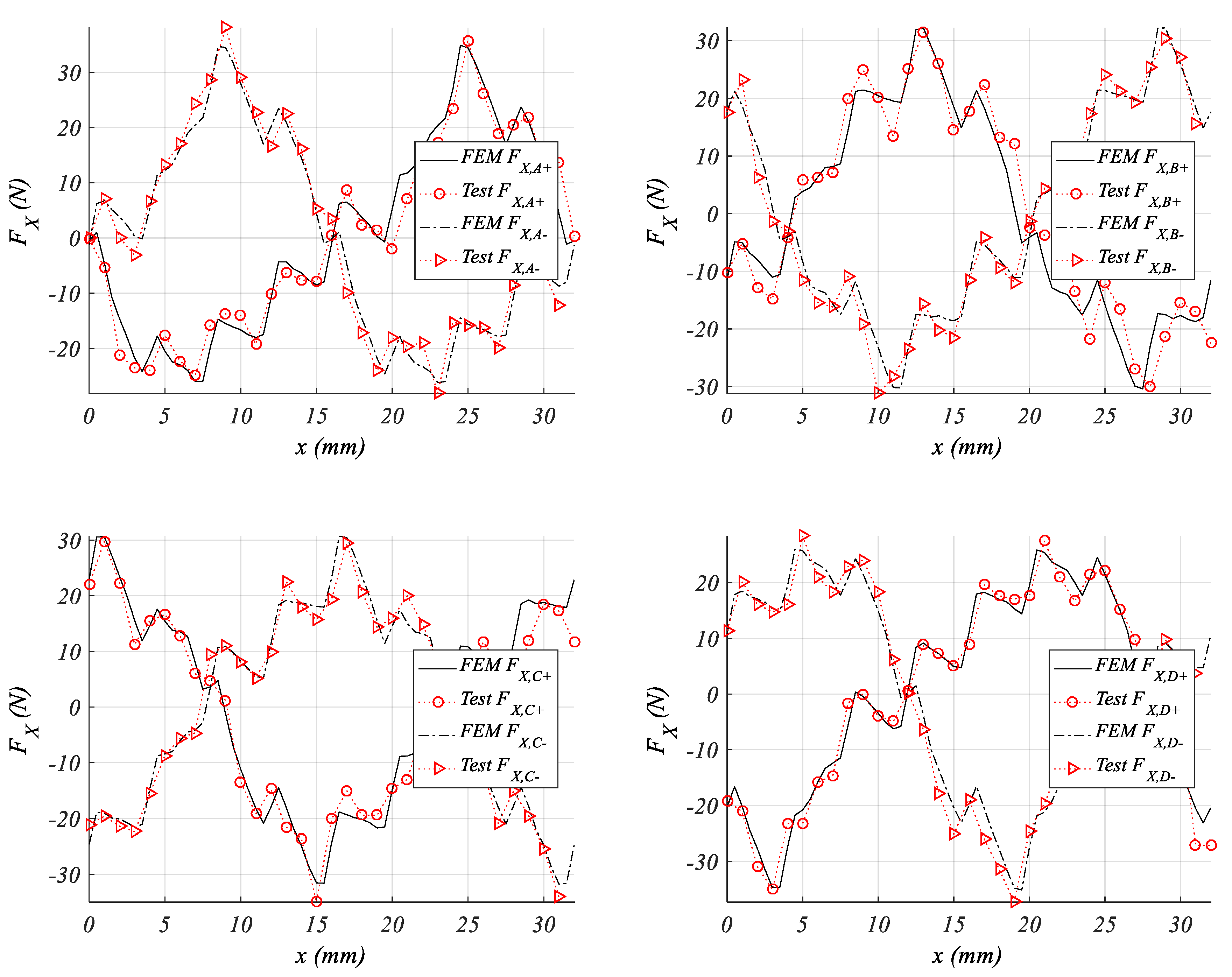
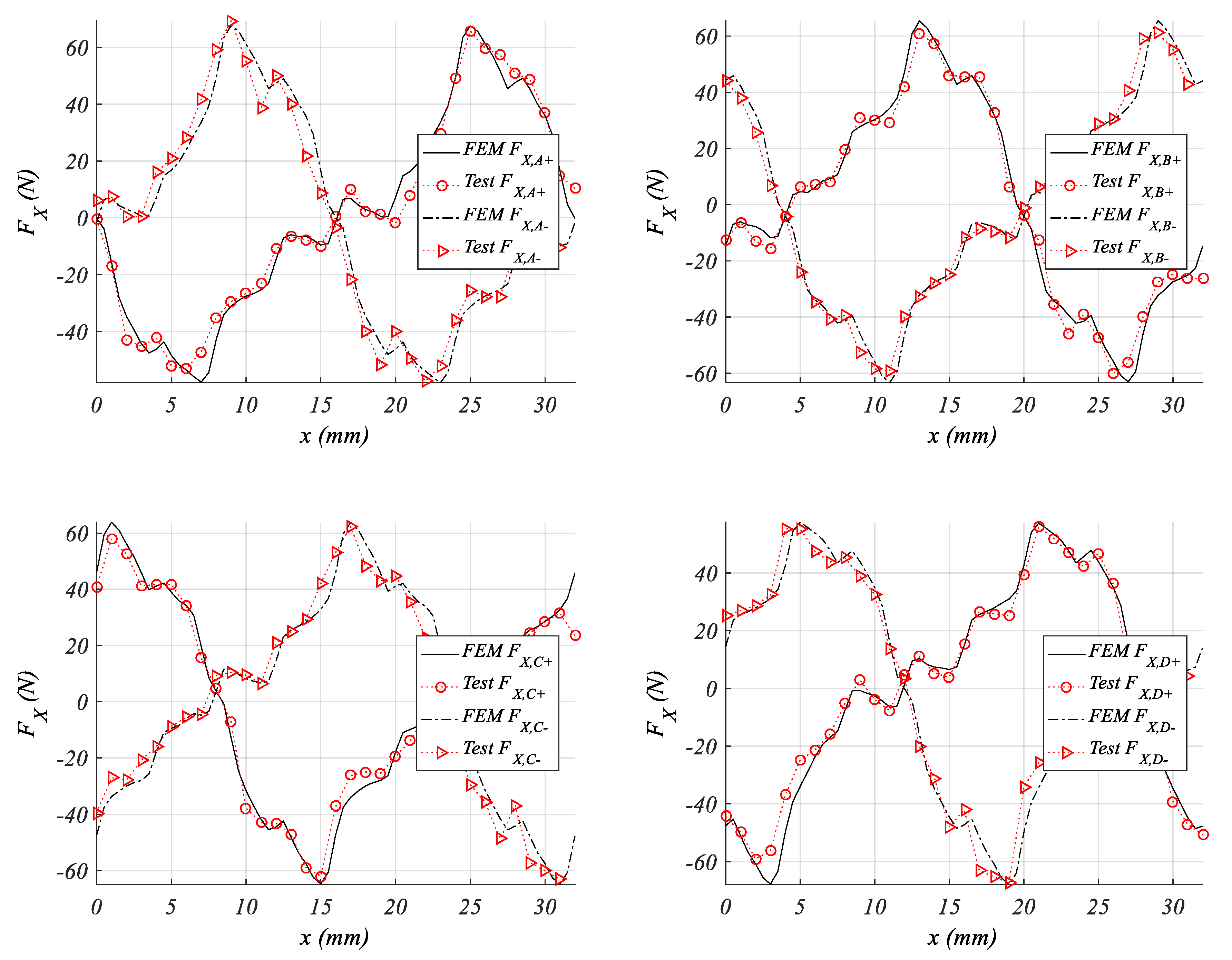
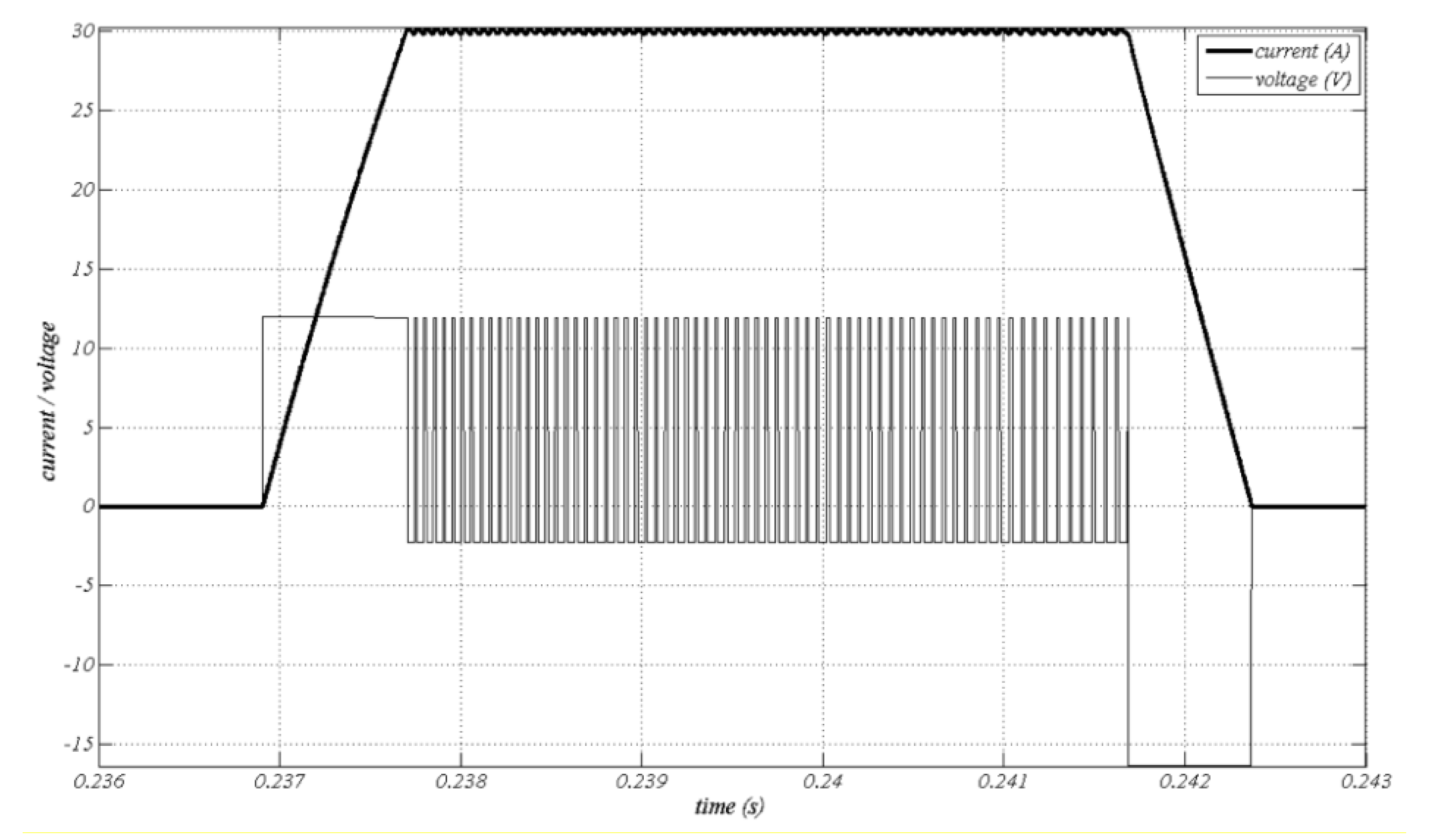
5. Experimental Results

In order to validate the FEM results, an LHRM prototype (see Figure 9b,c) was built and tested, with the main dimensions shown in Table A1. The experimental setup (see Figure 9a) consists of a system for positioning the mover at a given position and a load cell for measuring the static thrust force. The force is measured in each millimeter, in the range x [ 0 ,   2 · τ S ] , which means 32 measures for the 6 current densities J [ ± 5 , ± 10 , ± 15 ] . Considering the four phases, the total number of measures is 4 × 6 × 32 = 768. These results are compared with the FEM results in Figure 10, Figure 11, Figure 12 and Figure 13. The experimental results are in agreement with the FEM results, which validates the FEM simulation results.

6. Conclusions and Discussion

From the experimental results, the operating principle and force profiles are validated and this enables the linear hybrid reluctance motor (LHRM) as a good candidate for applications with high force density. Unlike LSRM, this machine needs to operate through a four-phase full-bridge converter, in order to supply the phase current with the appropriate sign. As in LSRM, the mover position and currents must be acquired; therefore, a linear encoder and current sensors are required for implementing a force control. This force control can be designed for mitigating the force ripple (see Figure 7b) by adjusting the currents waveform [28], and thus the force can remain almost flat to its maximum value for each current density.
From the point of view of the cogging force (see Figure 13), this presents a series of peaks of about 10% of the peak force at J = 15 A/mm2, which is a reasonable value. Further research should be done to eliminate cogging force by phase-shifting, or by a sensitivity analysis in the pole’s proportions and number of phases.
The LHRM actuator presented in this paper is conceived as a servomotor used in manufacturing lines or precision positioning applications whose velocity is relatively low (ub < 2 m/s) and where the force control is required. For this reason, a typical hysteresis current control is adopted, which is robust and fast [29], being the current controlled around a reference value (Iref), and whose ripple depends on the hysteresis range. The shape of the controlled current and voltage are shown in Figure 14, and it is characterized by the turn on/off positions (see Table 3) and by the reference current, the value of which is directly linked to the desired propulsion force.
The inherent fault tolerance of the reluctance machines and thus of LSRMs is preserved in the LHRM, because once the damaged phase is removed, the LHRM keeps operating at a new diminished force, as can be inferred from Figure 7a.
The motor is easily assembled despite having to put permanent magnets in the mover slots (see Figure 9c), because flux lines attach the PM to the magnetic structure (see Figure 4) and there are no repulsion forces.
The thermal aspect is also good because PMs are in the secondary (passive) part, which allows high current densities in the primary (active) part for intermittent operation.
From all the findings reported above, this novel structure of linear hybrid reluctance motor can be an interesting option in applications, which requires a high thrust force for intermittent duty cycles, such as in manufacturing industries and robotic systems.

Funding

This research was funded by the Spanish Ministerio de Economia, Industria y Competitividad, under the Grant DPI2016-80491-R (AEI/FEDER, UE).

Conflicts of Interest

The author declare no conflict of interest.

Appendix A

Table A1. LHRM prototype main dimensions and rated values.
ParameterSymbolValue
Primary pole width b p 6 mm
Primary slot width c p 6 mm
Primary pole length l p 30 mm
Secondary pole width b s 7 mm
Secondary slot width c s 9 mm
Secondary pole length l s 7 mm
Mover height l s t 30 mm
Magnet width b m 8 mm
Magnet height l m 6.5 mm
Stack width L W 30 mm
Air gap lengthg0.5 mm
Phase wire diameterd0.5 mm
Number of wires per poleNph180
Rated voltage Ub120 V
Rated currentIb3 A
Rated powerPb150 W
Rated forceFX90 N
Rated speedub1.5 m/s
Duty cycleDC0.4
Magnetic steel gradeFeV 270/50 HA
Insulation gradeB-Class T = 80   ° C
Duty typeS3
Permanent MagnetNdFeB32

References

  1. Zhang, B.; Yuan, J.; Pan, J.; Wu, X.; Luo, J.; Qiu, L. Controllability and Leader-Based Feedback for Tracking the Synchronization of a Linear-Switched Reluctance Machine Network. Energies 2017, 10, 1728. [Google Scholar] [CrossRef]
  2. Andrada, P.; Blanque, B.; Martinez, E.; Perat, J.I.; Sanchez, J.A.; Torrent, M. Environmental and life cycle cost analysis of one switched reluctance motor drive and two inverter-fed induction motor drives. IET Electr. Power Appl. 2012, 6, 390–398. [Google Scholar] [CrossRef] [Green Version]
  3. Chen, H.; Nie, R.; Yan, W.A. Novel Structure Single-Phase Tubular Switched Reluctance Linear Motor. IEEE Trans. Magn. 2017, 53, 1–4. [Google Scholar] [CrossRef]
  4. Zhao, W.; Zheng, J.; Wang, J.; Liu, G.; Zhao, J.; Fang, Z. Design and Analysis of a Linear Permanent- Magnet Vernier Machine with Improved Force Density. IEEE Trans. Ind. Electr. 2016, 63, 2072–2082. [Google Scholar] [CrossRef]
  5. Enrici, P.; Dumas, F.; Ziegler, N.; Matt, D. Design of a High-Performance Multi-Air Gap Linear Actuator for Aeronautical Applications. IEEE Trans. Energy Convers. 2016, 31, 896–905. [Google Scholar] [CrossRef]
  6. Pan, J.F.; Wang, W.; Zhang, B.; Cheng, E.; Yuan, J.; Qiu, L.; Wu, X. Complimentary Force Allocation Control for a Dual-Mover Linear Switched Reluctance Machine. Energies 2018, 11, 23. [Google Scholar] [CrossRef]
  7. Andrada, P.; Blanqué, B.; Martínez, E.; Torrent, M.; Garcia-Amorós, J.; Perat, J.I. New Linear Hybrid Reluctance Actuator. In Proceedings of the International Conference on Electrical Machines (ICEM), Berlin, Germany, 1–4 September 2014. [Google Scholar]
  8. Andrada, P.; Blanque, B.; Martinez, E.; Torrent, M. A Novel Type of Hybrid Reluctance Motor Drive. IEEE Trans. Ind. Electr. 2014, 61, 4337–4345. [Google Scholar] [CrossRef]
  9. Ullah, S.; McDonald, S.; Martin, R.; Atkinson, G.J. A permanent magnet assisted switched reluctance machine for more electric aircraft. In Proceedings of the International Conference on Electrical Machines (ICEM), Lausanne, Switerland, 4–7 September 2016. [Google Scholar]
  10. Hwang, H.; Hur, J.; Lee, C. Novel permanent-magnet-assisted switched reluctance motor (I): Concept, design, and analysis. In Proceedings of the International Conference on Electrical Machines and Systems (ICEMS), Busan, Korea, 23–29 October 2013. [Google Scholar]
  11. Hua, W.; Cheng, M.; Zhu, Z.Q.; Howe, D. Analysis and Optimization of Back EMF Waveform of a Flux-Switching Permanent Magnet Motor. IEEE Trans. Energy Convers. 2008, 23, 727–733. [Google Scholar] [CrossRef]
  12. Hasegawa, Y.; Nakamura, K.; Ichinokura, O. Basic consideration of switched reluctance motor with auxiliary windings and permanent magnets. In Proceedings of the International Conference on Electrical Machines (ICEM), Marseille, France, 2–5 September 2012. [Google Scholar]
  13. Ding, W.; Yang, S.; Hu, Y.; Li, S.; Wang, T.; Yin, Z. Design Consideration and Evaluation of a 12/8 High-Torque Modular-Stator Hybrid Excitation Switched Reluctance Machine for EV Applications. IEEE Trans. Ind. Electr. 2017, 64, 9221–9232. [Google Scholar] [CrossRef]
  14. Afinowi, I.A.A.; Zhu, Z.Q.; Guan, Y.; Mipo, J.C.; Farah, P. Hybrid-Excited Doubly Salient Synchronous Machine with Permanent Magnets Between Adjacent Salient Stator Poles. IEEE Trans. Magn. 2015, 51, 1–9. [Google Scholar] [CrossRef]
  15. Lobo, N.S.; Lim, H.S.; Krishnan, R. Comparison of Linear Switched Reluctance Machines for Vertical Propulsion Application: Analysis, Design, and Experimental Correlation. IEEE Trans. Ind. Appl. 2008, 44, 1134–1142. [Google Scholar] [CrossRef]
  16. Lee, S.; Kim, S.; Saha, S.; Zhu, Y.; Cho, Y. Optimal Structure Design for Minimizing Detent Force of PMLSM for a Ropeless Elevator. IEEE Trans. Magn. 2014, 50, 1–4. [Google Scholar] [CrossRef]
  17. Lin, J.; Cheng, K.W.E.; Zhang, Z.; Cheung, N.C.; Xue, X. Adaptive sliding mode technique-based electromagnetic suspension system with linear switched reluctance actuator. IET Electr. Power Appl. 2015, 9, 50–59. [Google Scholar] [CrossRef]
  18. Chen, Y.; Cao, M.; Ma, C.; Feng, Z. Design and Research of Double-Sided Linear Switched Reluctance Generator for Wave Energy Conversion. Appl. Sci. 2018, 8, 1700. [Google Scholar] [CrossRef]
  19. Wang, M.; Li, L.; Pan, D. Detent Force Compensation for PMLSM Systems Based on Structural Design and Control Method Combination. IEEE Trans. Ind. Electr. 2015, 62, 6845–6854. [Google Scholar] [CrossRef]
  20. Hao, W.; Wang, Y. Comparison of the Stator Step Skewed Structures for Cogging Force Reduction of Linear Flux Switching Permanent Magnet Machines. Energies 2018, 11, 2172. [Google Scholar] [CrossRef]
  21. Hasanien, H.M. Particle Swarm Design Optimization of Transverse Flux Linear Motor for Weight Reduction and Improvement of Thrust Force. IEEE Trans. Ind. Electr. 2011, 58, 4048–4056. [Google Scholar] [CrossRef]
  22. Huang, X.; Tan, Q.; Wang, Q.; Li, J. Optimization for the Pole Structure of Slot-Less Tubular Permanent Magnet Synchronous Linear Motor and Segmented Detent Force Compensation. IEEE Trans. Appl. Supercond. 2016, 26, 1–5. [Google Scholar] [CrossRef]
  23. Amorós, J.G.; Andrada, P.; Blanque, B.; Marin-Genesca, M. Influence of Design Parameters in the Optimization of Linear Switched Reluctance Motor under Thermal Constraints. IEEE Trans. Ind. Electr. 2018, 65, 1875–1883. [Google Scholar] [CrossRef]
  24. Garcia-Amoros, J.; Molina, B.B.; Andrada, P. Modelling and simulation of a linear switched reluctance force actuator. IET Electr. Power Appl. 2013, 7, 350–359. [Google Scholar] [CrossRef]
  25. Meeker, D.C. Finite Element Method Magnetics, Version 4.2 (28 February 2018 Build). Available online: http://www.femm.info (accessed on 16 October 2018).
  26. Henrotte, F.; Deliège, G.; Hameyer, K. The eggshell method for the computation of electromagnetic forces on rigid bodies in 2D and 3D. In Proceedings of the Conference on Electromagnetic Field Computation CEFC, Perugia, Italy, 16–18 April 2002. [Google Scholar]
  27. Nogueira, A.F.L. Analysis of magnetic force production in slider actuators combining analytical and finite element methods. J. Microw. Optoelectron. Electromagn. Appl. 2011, 10, 243–250. [Google Scholar] [CrossRef] [Green Version]
  28. Schramm, D.S.; Williams, B.W.; Green, T.C. Torque ripple reduction of switched reluctance motors by phase current optimal profiling. In Proceedings of the Conference on IEEE Power Electronics Specialists Conference. PESC’92 Record, Toledo, Spain, 29 June–3 July 1992. [Google Scholar]
  29. Dorningos, J.L.; Andrade, D.A.; Freitas, M.A.A.; De Paula, H. A new drive strategy for a linear switched reluctance motor. In Proceedings of the Conference on IEEE International Electric Machines and Drives IEMDC’03, Madison, WI, USA, 1–4 June 2003. [Google Scholar]
Figure 1. Longitudinal flux linear hybrid reluctance motor (LHRM) arrangement.
Energies 11 02805 g001
Figure 2. Linear hybrid reluctance motor main flux paths. (a) Phase A excited with I A + , positive force F X , A + . (b) Phase A excited with I A , negative force F X , A .
Energies 11 02805 g002
Figure 3. Linear hybrid reluctance motor operating principle. (a) Unaligned mover position. x = 0 mm, F X = 0 . (b) Aligned position. x = 1 2 · τ s mm, F X > 0 . (c) Unaligned position. x = τ s mm, F X = 0 . (d) Aligned position. x = 3 2 · τ s mm, F X < 0 .
Energies 11 02805 g003
Figure 4. Two-dimensional-finite element analysis (FEM) flux plot for I A = I B = I C = I D = 0 at x = 0 mm.
Energies 11 02805 g004
Figure 5. FEM propulsion force comparison results for linear switched reluctance motor (LSRM) and LHRM at J = ± 15 A/mm2. (a) Phase A. (b) Phase B. (c) Phase C. (d) Phase D.
Energies 11 02805 g005
Figure 6. Cogging force FEM result.
Energies 11 02805 g006
Figure 7. FEM results. (a) J = ± 15 A/mm2, all phases propulsion force, total propulsion force (red thick line) and conduction interval for phase A. (b) Total propulsion force at J [ ± 5 , ± 10 , ± 15 ] .
Energies 11 02805 g007
Figure 8. FEM results for the By component of the flux density. (a) By field for mover at 22 mm and feeding phase A at JA = +15 A/mm2. (b) By field for mover at 28 mm and feeding phase A at JA = −15 A/mm2. (c) By distribution field along the airgap, see red line in Figure 8a, for J = 0 and JA = 15 A/mm2. (d) By distribution field along the airgap, see red line in Figure 8b at J = 0 and JA = −15 A/mm2.
Energies 11 02805 g008aEnergies 11 02805 g008b
Figure 9. LHRM prototype. (a) Experimental setup. (b) LHRM frontal view. (c) Mover magnets assembly.
Energies 11 02805 g009
Figure 10. Experimental vs. FEM simulation phase-force results for J = ± 5 A/mm2.
Energies 11 02805 g010
Figure 11. Experimental vs. FEM simulation phase-force results for J = ± 10 A/mm2.
Energies 11 02805 g011
Figure 12. Experimental vs. FEM simulation phase-force results for J = ± 15 A/mm2.
Energies 11 02805 g012
Figure 13. Experimental vs. FEM simulation cogging force results.
Energies 11 02805 g013
Figure 14. Current and voltage waveforms simulation results (current × 10 1 ; voltage × 10 1 ).
Energies 11 02805 g014
Table 1. Two-dimensional-finite element analysis (FEM) comparison results for the linear hybrid reluctance motor (LHRM) and linear switched reluctance motor (LSRM).
Phase-A, ( I A = 2.95   A ) LHRMLSRM F X , A   ( % )
Average   force   ( N )   for   F X , A > 0 14223.182
Average   force   ( N )   for   F X , A < 0 1−43.2−23.187
Positive peak force (N)99.135.2181
Negative peak force (N)−90−35157
1 The average force is computed for positive and negative semi-periods.
Table 2. Phase comparison LHRM main results.
J = 15   A / mm 2 ,   ( I = 2.95   A ) F X , A + F X , B + F X , C + F X , D + F C o g g i n g
Average   force   ( N )   for   F X > 0 4245.742.9422.93
Average   force   ( N )   for   F X < 0 −43.2−42.7−45.5−42−2.91
Positive peak force (N)99.196.494.890.18.8
Negative peak force (N)−90-94.6−96.2−99−8.8
Table 3. Turn on/off phase excitation.
Excited Phase Turn   on   Position ,   x o n Turn   off   Position ,   x o f f
A +8.5 mm12.5 mm
B +28.75 mm0.5 mm
C +16.75 mm20.25 mm
D + 4.5 mm8.75 mm
A −24.5 mm28.5 mm
B −12.75 mm16.5 mm
C −0.75 mm4.25 mm
D −20.5 mm24.25 mm

