Abstract
Double sided linear flux switching permanent magnet machines (DSLFSPMMs) exhibit high thrust force density, high efficiency, low cost and robust double salient secondary (stator) structures. The aforementioned unique features make DSLFSPMM suitable for long stroke applications. However, distorted flux linkage waveforms and high detent forces can exaggerate thrust force ripples and reduce their applicability in many areas. In order to enhance thrust force performance, reduce thrust force ripple ratio and total harmonic distortion (THD) of no-load flux linkages, two structure-based advancements are introduced in this work, i.e., asynchronous mover slot and stator tooth displacement technique (AMSSTDT) and the addition of an active permanent magnet end slot (APMES). Furthermore, single variable geometric optimization (SVGO) is carried out by the finite element method (FEM).
1. Introduction
Rotary machines used for translational motion exhibit low efficiency and high cost due to requirement of sophisticated gear systems for the conversion of rotational torques into linear thrust forces. Linear motors can provide a direct linear thrust force, increasing reliability due to the reduction of mechanical conversion system, faster dynamic response, and good overload capability. The linear permanent magnet synchronous machine (LPMSM), linear induction machine (LIM), linear direct current machine (LDCM), and linear switched reluctance machine (LSRM) are some competent candidates for translational motion applications. LPMSM shows the merit of high flux density, LIM exhibits advantage of low cost when compared with linear permanent magnet (PM) machines, LDCM requires simple speed control, and LSRM has the advantage of a robust stator structure. Conversely, the fabrication cost of LPMSM for long stroke applications is high due to the increased cost of rare earth PM materials [1]. LIMs have relatively complex construction, and require more elaborate control algorithms than linear PM machines. LDCMs have low speed-force gradient and high maintenance costs. LSRMs has demerits of high thrust ripples and lower power density when compared with linear PM machines [2].
The linear flux switching machine (LFSM) combines the features of LPMSMs and LSRMs with additional advantages of high power density [3], bipolar flux linkage, robust secondary (stator) structure, suitability for applications where ruggedness and high speed are concerned [4], lowered manufacturing cost [5], and compatibility with extreme environmental conditions [6] due to a better temperature control.
The double sided LFSM (DSLFSM) has a passive secondary (stator made of iron only) and a short moving primary (mover) encompassing PMs and armature windings (AW). Due to their passive secondary (stator), DSLFSPMMs can be considered as a competent candidate for short stroke and long stroke applications such as Maglev transportation [7], rail transportation [8], subways [9], electromagnetic launch technology [10], linear propulsion technology [11], wave energy generators, linear oil pumping actuators [12], and artificial hearts [13,14]. As shown in Figure 1, DSLFSMs can be broadly categorized according to; (a) geometric structure, and (b) excitation source. Based on geometric structure, DSLFSMs can be divided into: (a) double stator, and (b) double mover [15]. Double stator LFSMs can be further categorized as: (a) with yoke [16,17], and (b) without yoke [18,19]. Depending upon the excitation source, DSLFSMs can be divided into: (a) double sided linear flux switching permanent magnet machines (DSLFSPMMs) [20], (b) field excited DSLFSMs (FEDSLFSMs) [21], and (c) hybrid excited DSLFSMs (HEDSLFSMs) [22]. HEDSLFSMs utilize both PMs and field windings as excitation sources. LFSPMM with double mover topology is investigated in [7], whereas [23] examined the performance of a LFSPMM with a double stator topology. Comparison of double stator and double mover LFSM is performed in [24] and the authors claim an advantage of a low thrust force ratio for the DSLFSM structure with moving primary (mover). Analysis and design of a LFSPMM with a yokeless double stator conventional topology is presented in [25,26] and one with multitooth topology is presented in [27,28]. On the other hand, the multi-tooth configuration would result in more severe magnetic leakage on the mover pole, which could easily saturate the mover iron teeth even with a light electric load. Detailed study of LFSMs reveals that almost all topologies exhibit high detent force and thrust force ripple ratio due to “slot effect” and “end effect”. A remedy, i.e., introduction of multiple additional teeth is implemented for a single sided LFSM in [29]. However, this remedy is not yet investigated for DSLFSPMMs. Furthermore, the aforementioned solution increases the perpendicular length (x-direction) of the moving primary.
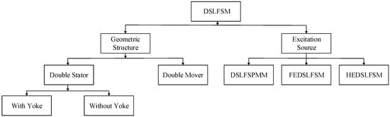
Figure 1.
Broad classification of DSLFSMs.
A field excited LFSM with double stator topology is designed and optimized in [30], and the authors recommended the proposed design for brushless AC (BLAC) operation. However, the field excited LFSM exhibits low thrust force density when compared with PM machines. Although the literature about HEDSLFSMs is very limited, a genetic algorithm (GA) optimization approach is utilized in [31] to reduce the thrust force ripple ratio while maintaining the average thrust force of a HEDSLFSM. Numerous advanced optimization techniques utilized for electric machines are presented in [32].
In this paper, a proposed DSLFSPMM (shown in Figure 2) is designed, investigated, modified, and optimized by the finite element method (FEM) utilizing the JMAG commercial FEA package v. 14. Design variables and initial parameters are illustrated in Figure 3 and Table 1, respectively. However, the initial DSLFSPMM design shows a low average thrust force, asymmetric no-load flux distribution and high thrust force ripple ratio. An asynchronous mover slot and stator tooth displacement technique (AMSSTDT) is the first modification introduced to enhance the average thrust force and reduce the thrust force ripple ratio. Addition of an active permanent magnet end slot (APMES) is the second alteration introduced in our modified DSLFSPMM design to effectively curtail the asymmetric no-load flux distribution problem, as illustrated in Section 2. Furthermore, the single variable geometric optimization (SVGO) technique is utilized to improve the overall performance of modified model in Section 3. Initial and optimized models are compared in Section 4. Finally, some conclusions are drawn in Section 5.
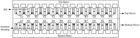
Figure 2.
2D cross-sectional view of DSLFSPMM.

Figure 3.
Design variables of DSLFSPMM.

Table 1.
Design parameters of DSLFSPMM.
2. Operating Principle and Enhancing Capabilities of DSLFSPMM
2.1. Operating Principle and Key Performance Indicators
The DSLFSPMM operating principle is described in Figure 4. When the relative position of the stator poles and a particular mover tooth is (assuming θe = 0°) as shown in Figure 4a, the coil U flux-linkage is assumed as positive maximum value. When the mover moves to position θe = 90° (Figure 4b) the flux linkage of coil U approaches a zero value. Flux linkage in coil U is assumed as a negative maximum value (Figure 4c) after further 90° movement i.e., θe = 180°. When the mover moves by further 90°, (θe = 270°, Figure 4d), the flux linkage of coil U again approaches zero value.
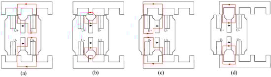
Figure 4.
Operating principle of DSLFSPMM: (a) θe = 0°; (b) θe = 90°; (c) θe = 180°; (d) θe = 270°.
Key performance indicators of DSLFSPMM such as peak-to-peak detent force () and average thrust force () are obtained from 2D FE Analysis. Triangular standard mesh with 2908 elements of 1 mm size and 1895 nodes is utilized to investigate each model of DSLFSPMM. Simulation time is almost four hours for each model while using a fifth generation Intel (R) Core (TM) i5 processor @ 1.70 Ghz with 8 GB RAM. No-load Flux THD () was obtained utilizing a Fourier transform, followed by Equation (1):
where is the fundamental component and to are the harmonic components. Thrust force ripple ratio was calculated using Equation (2) [8]:
where , , and are maximum value, minimum value, and ripples of thrust force, respectively.
2.2. Enhancing Capabilities
Remedies applied to DSLFSPMM for rectification of low average thrust force, asymmetric no-load flux distribution and high thrust force ripple ratio problems identified during initial design stage, are illustrated in this section. Introduced advancements are explained as follows:
2.2.1. Asynchronous Mover Slot and Stator Tooth Displacement Technique
The AMSSTD technique is introduced to enhance the average thrust force, reduce peak-to-peak detent force and thrust force ripple ratio. AMSSTDT is divided into two steps i.e., (a) mover slot displacement, and (b) stator tooth displacement. It is important to mention that coil configuration of top and bottom mover must be re-configured in order to achieve unidirectional thrust force, while implementing the AMSSTD technique.
(a) Mover Slot Displacement
Both top mover and bottom mover slot displacement is investigated by introducing a variable and , respectively (Figure 5). Numerical values of and are fractions of the mover pole pitch i.e., . Initially, the top mover slot is displaced, followed by bottom mover slot displacement, and eight different models are simulated. A performance comparison of all mover slot displaced designs with the initial design is shown in Figure 6. To distinguish the base machine configuration and improved (optimized/modified) machine configurations illustrated in subsequent figures, they are indicated by the use of different colors. The base machine configuration is indicated in red, whereas the improved (optimized/modified) machine configuration is shown in black. It can be seen that the maximum average thrust force with least no-load flux linkage THD and lowered peak-to-peak detent force can be achieved by selecting . Hence, DSLFSPMM with is selected for further analysis and is termed as DSLFSPMM Modified 1 (DSLFSPMM-M1) in this paper. Detailed comparison of DSLFSPMM with DSLFSPMM-M1 and modified parameters are listed in Table 2.
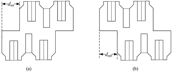
Figure 5.
Mover slot displacement variables: (a) Top mover slot displacement; (b) Bottom mover slot displacement.
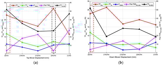
Figure 6.
Mover slot displacement results: (a) Comparison of displaced top mover slot designs with initial design; (b) Comparison of displaced bottom mover slot designs with initial design.
Table 2.
Modified parameters and performance comparison of DSLFSPMM with DSLFSPMM-M1.
(b) Stator Tooth Displacement
DSLFSPMM-M1 is further subjected to the stator tooth displacement technique to reduce the peak-to-peak detent force and thrust force ripple ratio. Both top stator and bottom stator tooth displacement is investigated by introducing a variable and , respectively (as shown in Figure 7). Numerical values of and are fractions of the stator pole pitch i.e., . Initially, the top stator tooth is displaced, followed by bottom stator tooth displacement, and six different models are simulated. A performance comparison of all displaced stator tooth designs with DSLFSPMM-M1 is shown in Figure 8, and detailed values are listed in Table 3. It can be seen that, the maximum average thrust force with least thrust force ripple ratio can be achieved by selecting . However, a slight increase in no-load flux linkage THD and peak-to-peak detent force is observed. Hence, DSLFSPMM-M1 with is selected for further analysis and is termed as DSLFSPMM-Modified 2 (DSLFSPMM-M2) in this paper. Detailed comparison of DSLFSPMM-M1 with DSLFSPMM-M2 and modified parameters are listed in Table 3.
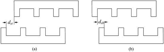
Figure 7.
Stator tooth displacement variables: (a) Top stator tooth displacement; (b) Bottom stator tooth displacement.
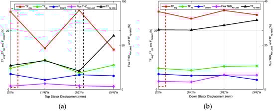
Figure 8.
Stator tooth displacement results: (a) Comparison of displaced top stator tooth designs with DSLFSPMM-M1; (b) Comparison of displaced bottom stator tooth designs with DSLFSPMM-M1.
Table 3.
Modified parameters and performance comparison of DSLFSPMM-M1 with DSLFSPMM-M2.
2.2.2. Addition of Active End PM Slot
The APMES technique is utilized to effectively curtail the asymmetric no-load flux distribution problem as shown in Figure 9b. Details of the no-load flux linkage, before and after APMES addition are listed in Table 4. Dimensions of the added APMES are identical to other slots, as illustrated in Table 1. However, the end tooth mover slot width, is adjusted to effectively utilize APMES. With this modification, PM volume is increased followed by an increment in average thrust force and a decrement in thrust force ripple ratio. A performance comparison of DSLFSPMM-M2 with and without APMES is shown in Figure 9c, and detailed values are listed in Table 5.
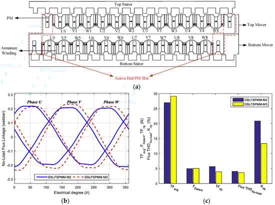
Figure 9.
DSLFSPMM-M3: (a) 2D cross-sectional view of DSLFSPMM-M3; (b) Comparison of no-load flux linkage symmetry for DSLFSPMM-M2 and DSLFSPMM-M3; (c) Comparison of key performance indicators for DSLFSPMM-M2 and DSLFSPMM-M3.
Table 4.
Comparison of no-load flux linkage symmetry for DSLFSPMM-M2 with and without APMES.
Table 5.
Modified parameter and performance comparison of DSLFSPMM-M2 with and without APMES.
It can be seen that the average thrust force and no-load flux linkage are increased, and the thrust force ripple ratio and no-load flux linkage THD are decreased, although a slight increase in peak-to-peak detent force is observed. Hence, DSLFSPMM-M2 with APMES is selected for further analysis and is termed as DSLFSPMM-M3 (as shown in Figure 9a) in this paper.
3. Single Variable Geometric Optimization (SVGO) of DSLFSPMM-M3
The SVGO technique, also known as deterministic optimization [25,28,33], is applied to increase the average thrust force and decrease peak-to-peak detent force, thrust force ripples, no-load flux linkage THD, and thrust force ripple ratio of DSLFSPMM-M3. Increase of average thrust force is set as a priority for the selection of machine configuration. However, in some cases where the proportion of increment in the average thrust force is less than the increment in detent force or thrust force ripple ratio, a machine configuration with increased average thrust force is sacrificed and that of low detent force and low thrust force ripple ratio is selected (machine configurations with such conditions are explained in the following sections). Electrical loading, stack length, air-gap length, stator pole pitch, and mover pole pitch are kept constant during the optimization process. SVGO is an optimization technique that sequentially modifies optimization variables and every consequent variable value may or may not depend upon a previous variable value [34]. SVGO enables reduced computational and time efforts compared to “simultaneous” optimization, but may lead to local optimal solutions rather than a global one. The SVGO technique also helps to investigate the effect of each optimization variable on machine performance. The following coefficients are defined in order to optimize , , , , , , , , , , , and . Initial values of the optimization variables are listed in Table 1.
Initial values and constraints of optimization coefficients are listed in Table 6 and are in accordance with general electric machine design rules [1]. The order of the optimization coefficients is the same one in which the optimization process is performed.
Table 6.
Optimization coefficients and constraints.
3.1. Influence of and
Neodymium iron boron (NdFeB) PMs (Neomax-35AH, K&J Magnetics, Inc., (Pipersville, PA, USA) are the strongest magnets, and used to simulate DSLFSPMM. The maximum recommended temperature for the NdFeB magnets is +220 degrees Centigrade and their demagnetization curves are shown in Figure A1 (Appendix A) [35].
The primary objective of these two optimization coefficients is to decrease PM volume and to enhance thrust force capabilities. Performance comparison of DSLFSPMM-M3 with different and ratios is done in Figure 10a,b, respectively. It can be seen that the overall performance of DSLFSPMM-M3 with reduced PM volume is degraded. Hence, is assumed as the optimal value with respect to the primary objective.
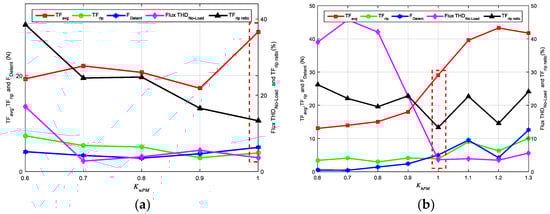
Figure 10.
Influence of PM dimensions on DSLFSPMM-M3: (a) Comparison of different values; (b) Comparison of different values.
The secondary objective of this optimization step is to enhance the thrust force capabilities while maintaining PM volume. and are varied with the condition that the overall PM volume remains unchanged. Performance comparison of DSLFSPMM-M3 with different and values subject to the aforementioned condition is done in Figure 11a.
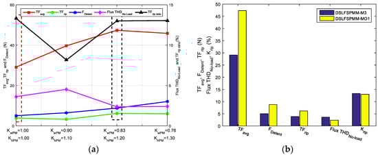
Figure 11.
Influence of PM dimensions on DSLFSPMM-M3, when PM volume is constant: (a) Comparison of DSLFSPMM-M3 with different and values; (b) Comparison of DSLFSPMM-M3 and DSLFSPMM-MO1.
It can be seen that the maximum average thrust force with minimum no-load flux linkage THD can be achieved by selecting and . However, a slight increase in thrust force ripples and peak-to-peak detent force is observed. Hence, DSLFSPMM-M3 with and is selected for further analysis and is termed as DSLFSPMM-MO1 in this paper. Performance comparison of DSLFSPMM-M3 with DSLFSPMM-MO1 is done in Figure 11b and detailed values are listed in Table 7.
Table 7.
Modified parameters and performance comparison of DSLFSPMM-M3 with DSLFSPMM-MO1.
3.2. Split Ratio Optimization
Split ratio is an important and detrimental parameter for the electromagnetic performance of a machine. Optimal selection of the split ratio enables a reduction of mover iron volume, hence reducing weight and cost while improving thrust force capability. It must be emphasized that PM volume, armature winding slot area, and electrical loading are fixed when the split ratio is varied. Key performance indicators of DSLFSPMM-MO1 with different split ratios are presented in Figure 12a.
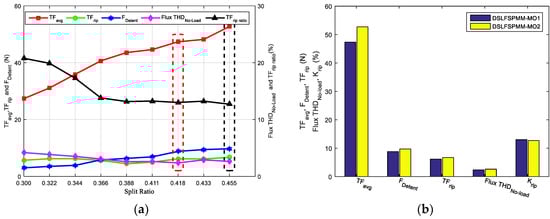
Figure 12.
Split ratio optimization: (a) Performance comparison of DSLFSPMM-MO1 with different split ratio; (b) Performance comparison of DSLFSPMM-MO1 and DSLFSPMM-MO2.
It can be observed that the maximum average thrust force with minimum thrust force ripple ratio can be achieved by selecting split ratio = 0.455. However, a slight increase in thrust force ripples, no-load flux linkage THD, and peak-to-peak detent force is observed. Hence, DSLFSPMM-MO1 with split ratio = 0.455 is selected for further analysis and is termed as DSLFSPMM-MO2 in this paper. Performance comparison of DSLFSPMM-MO1 with DSLFSPMM-MO2 is illustrated in Figure 12b, whereas, detailed values are tabulated in Table 8.
Table 8.
Modified parameters and performance comparison of DSLFSPMM-MO1 with DSLFSPMM-MO2.
3.3. Influence of
To investigate the influence of the mover tooth width on the average thrust force, peak-to-peak detent force, thrust force ripples, no-load flux linkage THD, and thrust force ripple ratio, DSLFSPMM-MO2 with different values should be investigated. Initially, is selected. Key performance indicators of DSLFSPMM-MO2 with different values are presented in Figure 13. It can be observed that the overall performance of DSLFSPMM-MO2 with is better than for other values, hence, no modification in is carried out.
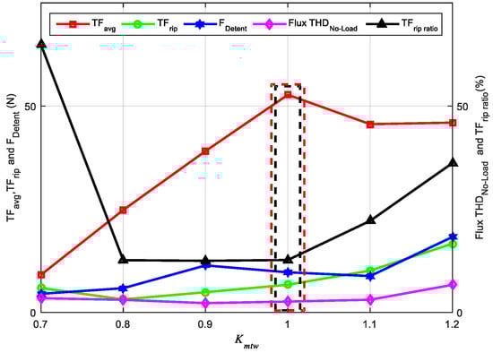
Figure 13.
Influence of on DSLFSPMM-MO2.
3.4. Influence of
As shown in Figure 2 and listed in Table 1, a mover tooth tip width is not equal to . To investigate the influence of the mover tooth tip width, a dedicated coefficient is defined and simulated for a range of 0.5 to 1.2. Performance comparison of DSLFSPMM-MO2 having different values of is shown in Figure 14a.
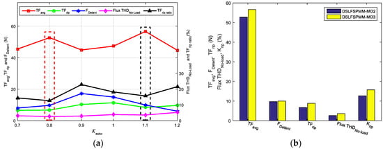
Figure 14.
Mover tooth tip width optimization: (a) Performance comparison of DSLFSPMM-MO2 having different values; (b) Performance comparison of DSLFSPMM-MO2 and DSLFSPMM-MO3.
It can be seen that the maximum average thrust force can be achieved by selecting . However, a slight increase in peak-to-peak detent force, thrust force ripples, no-load flux linkage THD, and thrust force ripple ratio is observed. Hence, DSLFSPMM-MO2 with is selected for further analysis and is termed as DSLFSPMM-MO3 in this paper. Performance comparison of DSLFSPMM-MO2 with DSLFSPMM-MO3 is illustrated in Figure 14b and detailed values are tabulated in Table 9.
Table 9.
Modified parameter and performance comparison of DSLFSPMM-MO2 with DSLFSPMM-MO3.
3.5. Influence of
The influence of mover tooth tip height on average thrust force, peak-to-peak detent force, thrust force ripples, no-load flux linkage THD, and thrust force ripple ratio is investigated by using the coefficient , and simulated for a range of 0.00 to 1.00. Key performance indicators of DSLFSPMM-MO3 having different values are presented in Figure 15a.
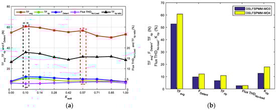
Figure 15.
Mover tooth tip height optimization: (a) Performance comparison of DSLFSPMM-O3 having different values; (b) Performance comparison of DSLFSPMM-MO3 and DSLFSPMM-MO4.
It can be seen that the maximum average thrust force no-load flux linkage THD can be achieved by selecting . However, a slight increase in peak-to-peak detent force, thrust force ripples, and thrust force ripple ratio is observed. Hence, DSLFSPMM-MO3 with is selected for further analysis and is termed as DSLFSPMM-MO4 in this paper. Performance comparison of DSLFSPMM-MO3 with DSLFSPMM-MO4 is illustrated in Figure 15b and detailed values are listed in Table 10.
Table 10.
Modified parameter and performance comparison of DSLFSPMM-MO3 with DSLFSPMM-MO4.
3.6. Influence of
The topology of DSLFSPMM allows for a completely passive stator (made only of iron) and is suitable for long stroke applications due to its reduced cost. Following general machine design rules, an initial value of is selected. Key performance indicators of DSLFSPMM-MO4 having different values are presented in Figure 16. It can be observed that the overall performance of DSLFSPMM-MO4 with is better than for other values; hence, no modification in is carried out.
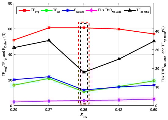
Figure 16.
Influence of on DSLFSPMM-MO4.
3.7. Influence of
is the ratio of stator tooth tip width to stator tooth width ( for DSLFSPMM-MO4). Both increase and decrease in are investigated by defining a range from 0.7 to 1.2. The performance comparison of DSLFSPMM-MO4 having different values of is shown in Figure 17a.
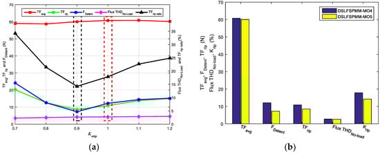
Figure 17.
Stator tooth tip width optimization: (a) Performance comparison of DSLFSPMM-MO4 having different values; (b) Performance comparison of DSLFSPMM-MO4 and DSLFSPMM-MO5.
It can be seen that when , the minimum value peak-to-peak detent force, thrust force ripples, and thrust force ripple ratio can be achieved, however, the average thrust force is about 98.78% of the maximum value at . Hence, DSLFSPMM-MO4 with is selected for further analysis and is termed as DSLFSPMM-MO5 in this paper. A performance comparison of DSLFSPMM-MO4 with DSLFSPMM-MO5 is illustrated in Figure 17b and detailed values are tabulated in Table 11.
Table 11.
Modified parameter and performance comparison of DSLFSPMM-MO4 with DSLFSPMM-MO5.
3.8. Influence of
The stator tooth base width is also optimized in order to reduce the peak-to-peak detent force and thrust force ripples. Similar to stator tooth tip ratio, both an increase and decrease in is investigated by defining a range from 0.7 to 1.3. The performance comparison of DSLFSPMM-MO5 having different values of is shown in Figure 18a.
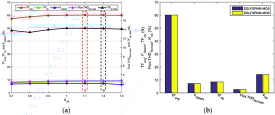
Figure 18.
Stator tooth base width optimization: (a) Performance comparison of DSLFSPMM-MO5 having different values; (b) Performance comparison of DSLFSPMM-MO5 and DSLFSPMM-MO6.
It can be observed that when , the average thrust force is about 99.91% of the maximum value at , whereas, the peak-to-peak detent force and thrust force ripples of DSLFSPMM-MO5 having is 98.76% and 99.41% to that of , respectively. Hence, DSLFSPMM-MO5 with is selected for further analysis and is termed as DSLFSPMM-MO6 in this paper. Performance comparison of DSLFSPMM-MO5 with DSLFSPMM-MO6 is illustrated in Figure 18b, whereas, detailed values are listed in Table 12.
Table 12.
Modified parameter and performance comparison of DSLFSPMM-MO5 with DSLFSPMM-MO6.
3.9. Influence of
The influence of stator tooth height on average thrust force, peak-to-peak detent force, thrust force ripples, no-load flux linkage THD, and thrust force ripple ratio is investigated by coefficient . The range of is selected from 0.2 to 0.8. Key performance indicators of DSLFSPMM-MO6 having different values are presented in Figure 19a.
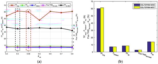
Figure 19.
Stator tooth height optimization: (a) Performance comparison of DSLFSPMM-MO6 having different values; (b) Performance comparison of DSLFSPMM-MO6 and DSLFSPMM-MO7.
It can be seen that the maximum average thrust force with minimum peak-to-peak detent force can be achieved by selecting . However, a slight increase in no-load flux linkage THD is observed. Also thrust force ripples and thrust force ripple ratio is reduced. Hence, DSLFSPMM-MO6 with is selected as final optimized model and is termed as DSLFSPMM-MO7 in this paper. Performance comparison of DSLFSPMM-MO6 with DSLFSPMM-MO7 is illustrated in Figure 19b, while detailed values are tabulated in Table 13. The comparison of the initial and optimized geometric parameters is summarized in Table 14.
Table 13.
Modified parameter and performance comparison of DSLFSPMM-MO6 with DSLFSPMM-MO7.
Table 14.
Comparison of initial and optimized geometric parameters.
Conclusions drawn from the optimization process may be listed as follows:
- (1)
- As a PM is an active source, the influence of PM dimensions greatly affect the average thrust force. Although the armature winding slot area is constant, reducing PM width helps to increase armature winding slot width and slot opening. This enhances flux linkage and average thrust force. PM height is increased and armature winding slot height is decreased in order to maintain the PM volume and armature winding slot area.
- (2)
- Split ratio is directly proportional to the height of the stator portion and inversely proportional to whole machine height. As can be witnessed in Section 3.2, an increased value of the split ratio is selected as the optimal value, and hence, mover volume and weight are reduced. This reduction helps to improve the average thrust force profile.
- (3)
- Although an increment of mover tooth tip width helps to improve the average thrust force, it is at the cost of an increase in thrust force ripple ratio. The reason behind the increment of thrust force ripple ratio is an increase in the slotting effect of the detent force.
- (4)
- Mover tooth tip height effect mover volume and low reluctance path (iron) to short circuit PM mmf. As can be seen in Section 3.5, a decreased value of mover tooth tip height is selected as an optimal value. This reduction helps to reduce mover weight and increase the high reluctance path (air) at the opening of the PM.
- (5)
- Stator tooth tip width is related to the slotting effect of detent force. A reduction in stator tooth tip width resulted in a decrease of detent force and thrust force ripple ratio at the cost of a slight decrease in average thrust force.
- (6)
- Although the stator tooth base width and stator tooth height do not have a significant effect on overall machine performance, however, an increase in stator tooth base width and decrease in stator tooth height results in an increase of the low reluctance path (iron). This increment enhances magnetic flux distribution and average thrust force profile.
4. Performance Comparison
Steady state and electromagnetic performance of DSLFSPMM (initial design, as shown in Figure 2) and DSLFSPMM-MO7 (modified and optimized design, as shown in Figure 20) is investigated and compared in this section.
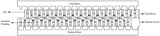
Figure 20.
2D cross-sectional view of DSLFSPMM-MO7.
The three phase no-load flux linkage waveforms obtained by the FE method for DSLFSPMM and DSLFSPMM-MO7 are compared in Figure 21a. It can be seen that the no-load flux linkage of DSLFSPMM-MO7 is higher in magnitude, more symmetrical and more sinusoidal than that of DSLFSPMM. Slight asymmetry is observed in the W phase of DSLFSPMM-MO7; a possible reason is the “end effect” (an inherent property of linear machines) [7,33]. Harmonic analysis (shown in Figure 21b) reveals that second-order, fifth-order and seventh-order harmonic components are curtailed effectively in the modified and optimized design, although the third-order, fourth-order, and sixth-order harmonic components of modified and optimized design are slightly high when compared with the initial design. According to the literature, third-order harmonic components can be counteracted in three-phase machines [10]. THD obtained from the frequency spectrum (shown in Figure 21b) of no-load flux linkage waveform for DSLFSPMM is 3.78% and for DSLFSPMM-MO7 is 2.73%.
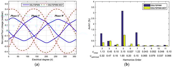
Figure 21.
Comparison of DSLFSPMM and DSLFSPMM-MO7: (a) No-load flux linkage waveforms; (b) No-load flux linkage frequency spectrum.
Figure 22a shows the thrust force comparison of DSLFSPMM and DSLFSPMM-MO7 obtained by the FE method. The average thrust force of DSLFSPMM-MO7 is about 270.14% to that of DSLFSPMM. The detent force waveforms obtained by the FE method for DSLFSPMM and DSLFSPMM-MO7 are compared in Figure 22b. It can be seen that the detent force of DSLFSPMM-MO7 is unidirectional and slightly higher in magnitude when compared with DSLFSPMM, whereas, the thrust force ripple ratio is reduced from 51.76% (DSLFSPMM) to 13.89% (DSLFSPMM-MO7). The performance comparison of DSLFSPMM and DSLFSPMM-MO7 is illustrated in Figure 23, while detailed values are tabulated in Table 15.
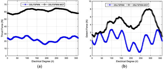
Figure 22.
Comparison of DSLFSPMM and DSLFSPMM-MO7: (a) Thrust force; (b) No-load detent force.
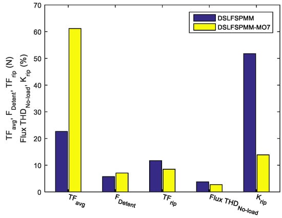
Figure 23.
Performance comparison of DSLFSPMM and DSLFSPMM-MO7.
Table 15.
Performance comparison of DSLFSPMM and DSLFSPMM-MO7.
In order to calculate contribution of PM volume on the average thrust force, a dedicated variable termed as thrust force density due to PM is defined as under:
for DSLFSPMM (initial design) is 0.00048996 m3 and 0.00058212 m3 for DSLFSPMM-MO7 (modified and optimized design). An increase in of DSLFSPMM-MO7 can be observed; the reason behind this increment is the addition of APMES. calculated for DSLFSPMM is 46.20 kN/m3 and 105.06 kN/m3 for DSLFSPMM-MO7.
5. Conclusions
In this paper, key performance indicators of a double sided linear flux switching permanent magnet machine (DSLFSPMM) i.e., average thrust force, peak-to-peak detent force, thrust force ripples, no-load flux linkage THD, and thrust force ripple ratio are investigated and enhanced by the FE method. Asynchronous mover slot and stator tooth displacement technique (AMSSTDT) is utilized to enhance the average thrust force, reduce peak-to-peak detent force and thrust force ripple ratio. The active permanent magnet end slot (APMES) technique is utilized to effectively curtail the asymmetric no-load flux distribution problem. After the aforementioned modifications, single variable geometric optimization (SVGO) is carried out. The thrust force of the modified and optimized model is about 270.14% to that of the initial model. The thrust force ripple ratio of the initial model is 51.76%, whereas that of the modified and optimized model is 13.89%. THD is also reduced from 3.78% to 2.73%, when compared with the initial model.
Author Contributions
Conceptualization, N.U.; Methodology, M.S.; Software, W.U.; Validation, M.S.; Formal Analysis, N.U.; Investigation, W.U.; Resources, F.K.; Data Curation, A.Z.; Writing—Original Draft Preparation, N.U.; Writing—Review & Editing, N.U.; Visualization, F.K.; Supervision, A.B. and F.K.; Project Administration, A.B. and F.K.
Funding
This research received no external funding.
Conflicts of Interest
The authors declare no conflict of interest.
Appendix A

Figure A1.
Demagnetization curves of NdFeB (Neomax-35AH).
References
- Cao, R.; Cheng, M.; Mi, C.C.; Hua, W. Influence of leading design parameters on the force performance of a complementary and modular linear flux-switching permanent-magnet motor. IEEE Trans. Ind. Electron. 2014, 61, 2165–2175. [Google Scholar] [CrossRef]
- Chau, K.T.; Chan, C.C.; Liu, C. Overview of permanent-magnet brushless drives for electric and hybrid electric vehicles. IEEE Trans. Ind. Electron. 2008, 55, 2246–2257. [Google Scholar] [CrossRef]
- Wang, C.F.; Shen, J.X.; Wang, Y.; Wang, L.L.; Jin, M.J. A new method for reduction of detent force in permanent magnet flux-switching linear motors. IEEE Trans. Magn. 2009, 45, 2843–2846. [Google Scholar] [CrossRef]
- Ou, J.; Liu, Y.; Schiefer, M.; Doppelbauer, M. A novel PM-free high-speed linear machine with amorphous primary core. IEEE Trans. Magn. 2017, 53, 1–8. [Google Scholar] [CrossRef]
- Hwang, C.C.; Li, P.L.; Liu, C.T. Design and analysis of a novel hybrid excited linear flux switching permanent magnet motor. IEEE Trans. Magn. 2012, 48, 2969–2972. [Google Scholar] [CrossRef]
- Ullah, N.; Khan, F.; Ullah, W.; Basit, A.; Umair, M.; Khattak, Z. Analytical Modelling of Open-Circuit Flux Linkage, Cogging Torque and Electromagnetic Torque for Design of Switched Flux Permanent Magnet Machine. J. Magn. 2018, 23, 253–266. [Google Scholar] [CrossRef]
- Zhao, W.; Cheng, M.; Ji, J.; Cao, R.; Du, Y.; Li, F. Design and analysis of a new fault-tolerant linear permanent-magnet motor for maglev transportation applications. IEEE Trans. Appl. Supercond. 2012, 22, 5200204. [Google Scholar] [CrossRef]
- Cao, R.; Cheng, M.; Mi, C.; Hua, W.; Wang, X.; Zhao, W. Modeling of a complementary and modular linear flux-switching permanent magnet motor for urban rail transit applications. IEEE Trans. Energy Convers. 2012, 27, 489–497. [Google Scholar] [CrossRef]
- Du, Y.; Jin, N. Research on characteristics of single-sided linear induction motors for urban transit. In Proceedings of the 2009 IEEE International Conference on Electrical Machines and Systems (ICEMS), Tokyo, Japan, 15–18 November 2009; pp. 1–4. [Google Scholar] [CrossRef]
- Huang, L.; Yu, H.; Hu, M.; Liu, H. Study on a long primary flux-switching permanent magnet linear motor for electromagnetic launch systems. IEEE Trans. Plasma Sci. 2013, 41, 1138–1144. [Google Scholar] [CrossRef]
- Duan, J.A.; Zhou, H.B.; Guo, N.P. Electromagnetic design of a novel linear maglev transportation platform with finite-element analysis. IEEE Trans. Magn. 2011, 47, 260–263. [Google Scholar] [CrossRef]
- Liu, J.; Huang, L.; Yu, H.; Wen, C.; Zhong, W. Study on the characteristics of a novel six-phase fault-torrent linear permanent magnet machine for linear oil pumping. IEEE Trans. Appl. Supercond. 2014, 24, 1–5. [Google Scholar] [CrossRef]
- Hodgins, N.; Keysan, O.; McDonald, A.S.; Mueller, M.A. Design and testing of a linear generator for wave-energy applications. IEEE Trans. Ind. Electron. 2012, 59, 2094–2103. [Google Scholar] [CrossRef]
- Ji, J.; Yan, S.; Zhao, W.; Liu, G.; Zhu, X. Minimization of cogging force in a novel linear permanent-magnet motor for artificial hearts. IEEE Trans. Magn. 2013, 49, 3901–3904. [Google Scholar] [CrossRef]
- Cao, R.; Huang, W.; Cheng, M. A new modular and complementary double sided linear flux-switching permanent magnet motor with yokeless secondary. In Proceedings of the 2014 IEEE International Conference on Electrical Machines and Systems (ICEMS), Hangzhou, China, 22–25 October 2014; pp. 3648–3652. [Google Scholar] [CrossRef]
- Krop, D.C.J.; Encica, L.; Lomonova, E.A. Analysis of a novel double sided flux switching linear motor topology. In Proceedings of the 2010 IEEE International Conference on Electrical Machines (ICEM), Rome, Italy, 6–8 September 2010; pp. 1–5. [Google Scholar] [CrossRef]
- Zhang, B.; Cheng, M.; Zhang, M.; Wang, W.; Jiang, Y. Comparison of modular linear flux-switching permanent magnet motors with different mover and stator pole pitch. In Proceedings of the 2017 IEEE International Conference on Electrical Machines and Systems (ICEMS), Sydney, Australia, 11–14 August 2017; pp. 1–5. [Google Scholar] [CrossRef]
- Gandhi, A.; Mohammadpour, A.; Sadeghi, S.; Parsa, L. Doubled-sided FRLSM for long-stroke safety-critical applications. In Proceedings of the 2011 IEEE International Conference on Industrial Electronics Society, Melbourne, Australia, 7–10 November 2011; pp. 4186–4191. [Google Scholar] [CrossRef]
- Gandhi, A.; Parsa, L. Double-sided flux-switching linear synchronous machine with yokeless translator. In Proceedings of the IEEE Energy Conversion Congress and Exposition, Raleigh, NC, USA, 15–20 September 2012; pp. 2676–2680. [Google Scholar] [CrossRef]
- Hao, W.; Wang, Y.; Deng, Z. Study of two kinds of double-sided yokeless linear flux-switching permanent magnet machines. In Proceedings of the 2016 Vehicle Power and Propulsion Conference (VPPC), Hangzhou, China, 17–20 October 2016; pp. 1–6. [Google Scholar] [CrossRef]
- Jin, Y.; Cao, R.; Zhang, Y.; Jiang, X.; Huang, W. A new double-sided primary wound field flux-switching linear motor. In Proceedings of the 2015 IEEE International Conference on Electrical Machines and Systems (ICEMS), Pattaya, Thailand, 25–28 October 2015; pp. 243–247. [Google Scholar] [CrossRef]
- Gandhi, A.; Parsa, L. Hybrid flux-switching linear machine with fault-tolerant capability. In Proceedings of the 2015 IEEE International Electric Machines Drives Conference (IEMDC), Coeur d’Alene, ID, USA, 10–13 May 2015; pp. 715–720. [Google Scholar] [CrossRef]
- Xiao, F.; Du, Y.; Sun, Y.; Zhu, H.; Zhao, W.; Li, W.; Ching, T.W.; Qiu, C. A novel double-sided flux-switching permanent magnet linear motor. J. Appl. Phys. 2015, 117, 17B530. [Google Scholar] [CrossRef]
- Lu, Q.; Li, H.; Huang, X.; Ye, D.; Fang, Y.; Ye, Y. Investigation of double-sided multi-tooth switched-flux linear motor. In Proceedings of the 2015 IEEE International Conference on Electrical Machines and Systems (ICEMS), Pattaya, Thailand, 25–28 October 2015; pp. 237–242. [Google Scholar] [CrossRef]
- Gandhi, A.; Parsa, L. Thrust optimization of a flux-switching linear synchronous machine with yokeless translator. IEEE Trans. Magn. 2013, 49, 1436–1443. [Google Scholar] [CrossRef]
- Zhang, B.; Cheng, M.; Wang, J.; Zhu, S. Optimization and analysis of a yokeless linear flux-switching permanent magnet machine with high thrust density. IEEE Trans. Magn. 2015, 51, 1–4. [Google Scholar] [CrossRef] [PubMed]
- Lu, Q.; Li, H.; Huang, X.; Ye, Y. Research on yokeless double-sided multi-tooth flux-switching linear motor. COMPEL 2016, 35, 832–843. [Google Scholar] [CrossRef]
- Shen, Y.; Lu, Q.; Li, H.; Cai, J.; Huang, X.; Fang, Y. Analysis of a Novel Double-Sided Yokeless Multitooth Linear Switched-Flux PM Motor. IEEE Trans. Ind. Electron. 2018, 65, 1837–1845. [Google Scholar] [CrossRef]
- Du, Y.; Yang, G.; Quan, L.; Zhu, X.; Xiao, F.; Wu, H. Detent force reduction of a C-core linear flux-switching permanent magnet machine with multiple additional teeth. Energies 2017, 10, 318. [Google Scholar] [CrossRef]
- Cao, R.; Jin, Y.; Zhang, Y.; Cheng, M. A new double-sided HTS flux-switching linear motor with series magnet circuit. IEEE Trans. Appl. Supercond. 2016, 26, 1–5. [Google Scholar] [CrossRef]
- Liu, C.T.; Hwang, C.C.; Li, P.L.; Hung, S.S.; Wendling, P. Design optimization of a double-sided hybrid excited linear flux switching PM motor with low force ripple. IEEE Trans. Magn. 2014, 50, 1–4. [Google Scholar] [CrossRef]
- Lei, G.; Zhu, J.; Guo, Y.; Liu, C.; Ma, B. A review of design optimization methods for electrical machines. Energies 2017, 10, 1962. [Google Scholar] [CrossRef]
- Hao, W.; Wang, Y. Thrust Force Ripple Reduction of Two C-Core Linear Flux-Switching Permanent Magnet Machines of High Thrust Force Capability. Energies 2017, 10, 1608. [Google Scholar] [CrossRef]
- Lu, Q.; Yao, Y.; Shi, J.; Shen, Y.; Huang, X.; Fang, Y. Design and performance investigation of novel linear switched flux pm machines. IEEE Trans. Ind. Appl. 2017, 53, 4590–4602. [Google Scholar] [CrossRef]
- K&J Magnetics, Inc. Available online: https://www.kjmagnetics.com/bhcurves.asp (accessed on 9 September 2018).
© 2018 by the authors. Licensee MDPI, Basel, Switzerland. This article is an open access article distributed under the terms and conditions of the Creative Commons Attribution (CC BY) license (http://creativecommons.org/licenses/by/4.0/).