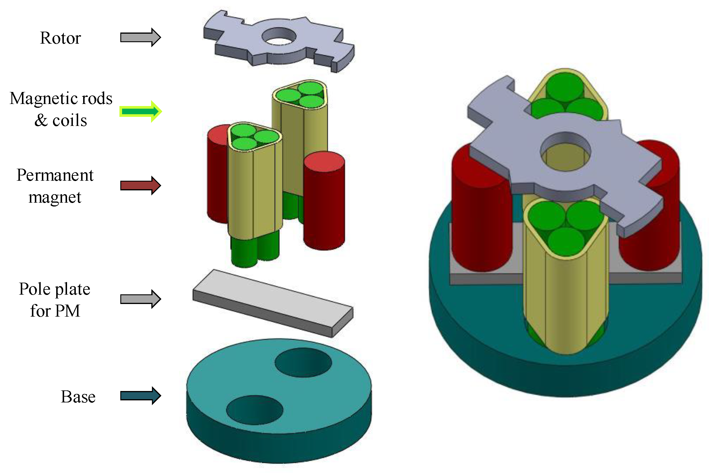
Article

A Wireless-Driven, Micro, Axial-Flux, Single-Phase Switched Reluctance Motor

Department of Mechanical Engineering, National Kaohsiung University of Science and Technology, 415 Jian Gong Rd., Sanmin Dist., Kaohsiung 80778, Taiwan
*
Author to whom correspondence should be addressed.
Energies 2018, 11(10), 2772; https://doi.org/10.3390/en11102772
Submission received: 31 July 2018 / Revised: 10 October 2018 / Accepted: 15 October 2018 / Published: 16 October 2018
(This article belongs to the Special Issue Electrical Machine Design)

Abstract

:
This study proposes a novel, axial-flux, single-phase switched reluctance motor for micro machines with wireless-driven capability. The rotor and stator each have two poles, and the stator utilizes two permanent magnets to provide the required parking position and rotational torque. By reducing the number of magnetic poles and coils in the stator, and by utilizing a cylindrical design for its stator components, the micro motor is able to be easily manufactured and assembled. Safety and convenience are also achieved through the use of a wireless drive, which negates the need for power connections or batteries. This study utilizes the topology method in rotor design to reduce excessive torque ripple. For this study, an actual micro, axial-flux, single-phase switched reluctance motor with a diameter of 5.5 mm and length of 4.4 mm was built in combination with a wireless charging module and motor circuitry found on the market. With an induced current of 0.7 A, the motor achieved a maximum of 900 rpm, indicating possible applications with respect to toys, micro-pumps, dosing pumps, and vessels for gases, liquids, or vacuum that do not require feedthrough.

1. Introduction

In 1984, Compter [1] developed the first single-phase switched reluctance motor with a two-pole rotor, two-pole stator, and two permanent magnets in the stator to solve the starting problem. Motor operation was improved by utilizing one positional sensor for control. In 1987, Chan [2] presented two single-phase switched reluctance motor designs, one for an axial-flux-type motor and the other for a radial-flux-type motor, with six poles in the rotors and stators. Horst [3,4] patented two single-phase switched reluctance motors with different rotor designs utilizing salient teeth and shifted poles. Both motors utilized two poles in the rotor and stator and one permanent magnet to provide a suitable starting position. In 1993, Torok and Loreth [5] fabricated a single-phase switched reluctance motor with four poles in the rotor and stator, two permanent magnets, and only two coils. In 1988, Lim et al. [6] proposed a single-phase switched reluctance motor with six poles in the rotor and stator with both axial and radial air gaps to increase torque output. In 2000, Stephenson and Jenkinson [7] produced a different design for a single-phase switched reluctance motor with four poles in the rotor and stator for high-speed fan applications. In 2001, Stanley [8] presented a single-phase switched reluctance motor with four poles in the rotor and stator without permanent magnets. The stator contained four sets of auxiliary coils to provide starting capability in both directions.
In 2003, Higuchi et al. [9] proposed a single-phase switched reluctance motor with a tooth-slotted rotor design that used the magnetic saturation effect to produce starting torque in any position instead of using permanent magnets. In 2010, Jakobsen and Lu [10] presented a single-phase switched reluctance motor with four poles in the stator and rotor with a new stator pole design and an arrangement of permanent magnets to improve the starting torque. In 2011, Lu et al. [11] proposed an improved design, especially with regards to the arrangement of the permanent magnets, for low-cost pump applications. In 2012, Asgar et al. [12] developed a single-phase switched reluctance motor with a four-pole stator and two-pole rotor that utilized a skewed rotor design without the use of permanent magnets. In 2013, Yang et al. [13] fabricated a single-phase switched reluctance motor with six poles in the stator and rotor that employed the same skewed angle, reducing the acoustic noise and vibration. In 2015, Xu et al. [14] proposed a single-phase hybrid switched reluctance motor with a two-pole stator and four-pole rotor for hammer-breaker applications. In 2016, Infanuti et al. [15] demonstrated a single-phase switched reluctance motor with a four-pole rotor and two-pole stator with Ferrite permanent magnets for better efficiency. The rotor poles had a variable air-gap to provide starting torque in any position. In 2017, Jeong et al. [16] produced a single-phase hybrid switched reluctance motor, with four poles in both the stator and rotor, which applied permanent magnets and a non-uniform air-gap to enable self-starting and reduce torque ripple.
Single-phase switched reluctance motors are the lowest-cost motor with the minimum number of components [17] and are especially suited for application in micro machines. However, past studies have not proposed any micro designs, as the smallest motor still has a diameter of 32 mm [12]. Axial-flux motors have a flat structure, produce a higher torque, and possess a higher torque density, making them suitable for application in places where space is limited. With the exception of one of the motors presented by Chan [2], the single-phase switched reluctance motors described above all utilize a radial-flux design; furthermore, while Chan proposed an axial-flux design, his design did not use any permanent magnets to assist starting.
This paper proposes a micro, axial-flux, single-phase switched reluctance motor with two poles for both the stator and rotor in combination with two permanent magnets to solve the issue of starting. The magnetic poles of the coils and permanent magnets utilize a cylindrical design for ease of manufacturing and assembly. The rotor structure was designed using the topology method to reduce torque ripple and avoid any dead zones. This research demonstrates the first wireless-driven, single-phase switched reluctance motor especially suited for micro machines, with possible future applications in toys, micro pumps, and gas, liquid, and vacuum containers that do not require feedthrough.

2. Micro Single-Phase Reluctance Switched Motor Design and Analysis

2.1. Single-Phase Switched Reluctance Motor Design

This motor was designed with a two-pole stator and two-pole rotor; two permanent magnets were placed on the stator. The diameter of the stator was 5.5 mm, its length was 4.4 mm, and the stator magnetic poles and permanent magnet utilized a cylindrical structure that facilitates the assembly of micro motors. As the magnetic rods utilized in the prototype design of this study are difficult to purchase, each stator pole was assembled using three magnetic rods made of nickel wire with a diameter of 0.75 mm. The permanent magnets were FLN8 AlNiCo magnets (Mingyen Electronics Industry Co., Ltd., Taichung, Taiwan). with axial magnetization. The rotor structure and pole plate utilized a 35CS300 silicon steel plate with a thickness of 0.35 mm. The design specifications of the single-phase switched reluctance motor are shown in Table 1; the exploded view and assembly drawings of the single-phase switched reluctance motor are shown in Figure 1.

2.2. Rotor Design of the Single-Phase Switched Reluctance Motor

The design of the single-phase switched reluctance motor was critical because improper design often produces zero or negative torque and excessive torque ripple, limiting performance and applications. This study first determined the stator structure including magnetic rods, coils, and permanent magnets, and then considered rotor structure. The design of this motor was determined using JMAG finite element analysis software developed by JSOL Corporation, Tokyo, Japan. Figure 2 shows the definitions of the coordinate and rotating angle of the motor so that the axis of the permanent magnets was at 0°.
This study utilized the topology optimization method for a new rotor design to increase the average torque and reduce torque ripple. The topology method is generally applied in prototype design to optimize the material layout within a given design space and for a given set of constraints, with the goal of maximizing its output performance. The design processes are separated into four steps. Step 1 is the pole thickness and root diameter design, step 2 is the first and third quadrant design, step 3 is the second and fourth quadrant design, and step 4 is the detailed design of the magnetic pole. As the rotor and stator of this motor both possess two poles, there is rotational symmetry, which makes the first and third quadrants and the second and fourth quadrants identical. This study focuses on the rotor structure design, using the JMAG software to analyze the torque output at every degree and calculate the average torque and relative torque ripple. The addition and subtraction of rotor structure were then made to optimize the design.
Relative torque ripple was defined as
  T r i p p l e =   T m a x T m i n T m a x + T m i n × 100 %  
The objective function is the maximum average torque and minimum relative torque ripple, and the set constraints are that the average torque must be greater than 14 μN·m and the relative torque ripple must be lower than 70%. These two values were selected after multiple analyses were performed. Even with a variety of different designs, the maximum average torque was 15.47 μN·m and the minimum relative torque ripple was 63.33%. The objective function was set as
Objective   function   =   T T C T C × 100 % + ( T r i p p l e C T r i p p l e )  
where T is the average torque and TC is the constraint of the average torque at 14 μN·m. Tripple is the relative torque ripple and TrippleC is the constraint of the relative torque ripple at 70%. The minimum value of the objective function was selected as the geometric shape for rotor optimization.

2.2.1. Step 1: Design of Rotor Magnetic Pole Width and Root Diameter

The first step of this study was to change the rotor magnetic pole width from 1.85 mm to 0.6 mm in decrements of 0.05 mm to achieve the optimal magnetic pole width of 1.6 mm. Next, the root diameter changed from 2.5 mm to 1.75 mm in decrements of 0.05 mm for an optimal root diameter of 2.0 mm. The design process is shown in Figure 3. In step 1-1, the rotor magnetic pole width was 1.85 mm and the root diameter was 2.5 mm; step 1-2 shows a rotor magnetic pole width of 1.6 mm and a root diameter of 2.5 mm, achieving the optimal magnetic pole width; step 1-3 shows a rotor magnetic pole width of 1.6 mm and a root diameter of 1.75 mm resulting in the worst average torque of 13.17 μN·m; step 1-4 shows that the rotor magnetic pole width was 1.6 mm and the root diameter was 2.0 mm for the best performance of step 1, with an average torque of 14.78 μN·m and relative torque ripple of 102.5%. The torque-angle curve of each process is shown in Figure 4, and a comparison of the torque characteristics is shown in Table 2.

2.2.2. Step 2: Design of Rotor Magnetic Pole Quadrants 1 and 3

Step 2 was the axial symmetrical topology design of the rotor magnetic poles for quadrants 1 and 3. The mesh dimensions were 0.25 mm × 0.25 mm. We began by establishing five-layer meshes by adding two layers of meshes to the original magnetic pole width; the outer layer was defined as layer 1 and layer 5 was the closest to the X-axis. The design process was shown in Figure 5. In step 2-1, the first design decreased the average torque and relative torque ripple but still generated a dead zone between the angles of 160°and 180°; step 2-2 removed the meshes of the first and second layers to solve the dead zone issue; step 2-3 removed the meshes from the third layer for an evident decrease in relative torque ripple; step 2-4 removed more meshes from the first four layers to achieve the best performance in step 2,with an average torque of 13.38 μN·m and a relative torque ripple of 83.75%. The torque-angle curve of each process is shown in Figure 6, and a comparison of the torque characteristics is shown in Table 3. It should be noted that removing the meshes from the fifth layer did not improve output performance.

2.2.3. Step 3: Design of Rotor Magnetic Pole Quadrants 2 and 4

Step 3 was the axial symmetrical topology design of the rotor magnetic poles for quadrants 2 and 4. The mesh dimensions were 0.25 mm × 0.25 mm. We began by establishing three-layer meshes; the outer layer was defined as layer 1 and layer 3 was closest to the X-axis. The design process is shown in Figure 7. In step 3-1, the design increased the average torque and decreased the relative torque ripple; step 3-2 removed the meshes from the first and second layers for an evident decrease in the average torque and relative torque ripple; step 3-3 removed more meshes from the first and second layers without any improvement; step 3-4 removed one mesh from the third layer of the step 3-2 design without any improvement; step 3-2 was chosen as the best design for step 3, with an average torque of 13.10 μN·m and a relative torque ripple of 79.09%. The torque-angle curve of each process is shown in Figure 8, and a comparison of the torque characteristics is shown in Table 4. It should be noted that the design of the rotor magnetic poles in quadrants 2 and 4 had a limited effect in terms of improving output performance.

2.2.4. Step 4: Detailed Design of the Rotor Magnetic Pole

Step 4 was the detailed design of the rotor magnetic pole by shrinking the mesh dimensions to 0.125 mm × 0.125 mm. Since the degree to which adjustments to the rotor magnetic poles in quadrants 2 and 4 improved the performance was limited, this step only presents the analysis results for the rotor magnetic poles in quadrants 1 and 3. We began by establishing nine-layer meshes; the outer layer was defined as layer 1 and layer 9 was the closest to the X-axis. The design process is shown in Figure 9. In step 4-1, the design added meshes to the first and second layer without any improvement; step 4-2 removed meshes from the first layer for an evident increase in average torque and relative torque ripple; step 4-3 removed meshes from the third, fourth, and fifth layers without any improvement; step 4-4 used a diagonal design for the salient pole for an evident increase in average torque and relative torque ripple; step 4-4 was selected as the best design for step 4, with an average torque of 13.75 μN·m and a relative torque ripple of 82.85%.The torque-angle curve of each process is shown in Figure 10, and a comparison of the torque characteristics is shown in Table 5.
The electromagnetic analysis results for the single-phase switched reluctance motor design using the topology method are presented in top view and 3D view diagrams in Figure 11, Figure 12, Figure 13 and Figure 14. The motor was driven by an input current of 1 A at angles between 0° and 90°, and by a permanent magnet at angles between 90° and 180°. The magnetic flux density distribution for when the coils began to excite at an angle of 0° is shown in Figure 11. The maximum flux density of 1.86 T occurred in the rotor, while a density of 0.91 T occurred in the air gap. The magnetic flux density distribution when the motor produced the maximum torque at an angle of 74° is shown in Figure 12. The maximum flux density of 1.94 T occurred in the rotor, while a density of 0.63 T occurred in the air gap. The magnetic flux density distribution when the current was switched off at an angle of 91° is shown in Figure 13. The maximum flux density of 0.99 T occurred in the pole plate, while a density of 0.29 T occurred in the air gap. The magnetic flux density distribution when the permanent magnet produced the maximum torque at an angle of 135° is shown in Figure 14. The maximum flux density of 1.05 T occurred in the pole plate, while a density of 0.27 T occurred in the air gap.
Since the maximum flux density of the rotor was larger than the 1.63 T from the manufacturer’s catalog, there was some concern regarding magnetic saturation, and this was confirmed later in the experiment. It should be noted that there was magnetic leakage at the bottom of the three magnetic rods, with this leakage being especially evident in Figure 13 and Figure 14, because the distance between the magnetic rods and the permanent magnets was too small. If three small magnetic rods are replaced by one large rod and the distance is increased, the problem will be solved; this was demonstrated in a simulation that is not shown here.

3. Fabrication and Testing of the Single-Phase Switched Reluctance Motor

3.1. Motor Fabrication

The parts of the single-phase switched reluctance motor were fabricated by mechanical machining processes and a prototype was hand-assembled. As shown in Figure 15, the components of the motor (from left to right) were the rotor, pole plate, permanent magnet, magnetic rod with coil, base, and fixture with fixed shaft. A top view of the motor prototype is shown in Figure 16. The rotor, pole plate, base, and fixture were made by wire electrical discharge machining. The magnetic rod used Goodfellow Cambridge Ltd. (Huntingdon, UK) NI005159 nickel wires that were cut and grinded before being wrapped around the coils. The permanent FLN8 AlNiCo magnet was produced by Mingyen Electronics Industry Co., Ltd. (Taichung, Taiwan). The assembly of the motor was carried out by first inserting the magnetic rod with coil into the base, placing the pole plate and permanent magnet on the base, and installing the fixture and fixed shaft. A copper wire with a diameter of 0.06 mm was wrapped around the fixed shaft to secure the axial air gap of the motor. The rotor was placed on the shaft to complete the assembly process.

3.2. Torque-Angle Curve Testing

The experimental testing of the torque-angle curve is very important for a single-phase switched reluctance motor because the output torque is varied at different angle positions. Torque is measured by hanging different small weights, metal balls and adhesive tapes on the outer diameter of the rotor [18]. Typically, the mass of the metal ball is 18 mg and the adhesive tape 1 mg. The total weight was measured using the Mettler-Toledo AB54 Analytical Balance (Mettler-Toledo AG, Greifensee, Switzerland) with a repeatability of 0.1 mg and a linear accuracy of 0.2 mg. The first test consisted of measuring the passive torque-angle curve at every 3° interval from 0° to 180° without any input current. The motor was designed to operate at a minimum activation current of 0.5 A and a maximum current of 1 A. The torque-angle curves were measured at currents from 0.5 A to 1 A in increments of 0.1 A at every 3° interval from 0° to 90°.
Table 6 shows the theoretical and experimental torque characteristics of the single-phase switched reluctance motor, including the minimum torque, maximum torque, average torque, and relative torque ripple, at various current levels. Figure 17 shows the theoretical and experimental torque-angle curves of the single-phase switched reluctance motor. The test results showed that the maximum detent torque was 12 μN·m at a 30° angle. At a minimum activation current of 0.5 A, the minimum torque was 1.54 μN·m, also at a 30° angle. When the current ranges from 0.6 A to 1 A, the minimum torque was always 1.92 μN·m at a 91° angle, meaning that the coil was no longer excited. When the rated current was 1 A, the motor produced an average torque of 10.34 μN·m with a relative torque ripple of 80.66%. It should be noted that the theoretical and experimental torque-angle curves did not match well at larger currents, and thus the motor friction was tested to clarify this issue.

3.3. Friction Testing

As friction greatly affects the performance of a micro motor, this test measures the friction torque by hanging tiny weights on the outer diameter of the rotor. For this test, the permanent magnets were removed and measurements were taken at every 3° interval between 0° and 360° to calculate the average friction torque, which was found to be 1.19 μN·m. In order to find the impact of the friction, it was assumed that the friction was entirely against the output torque. The study added the friction torque to the output torque, and the output characteristics were recalculated. Table 7 shows the calculated values of the maximum torque and average torque of the motor with and without friction correction. Figure 18 shows the theoretical and experimental torque–angle curves of the motor with friction correction. At a rated current of 1 A, the deviations between the theoretical and measured maximum torque and average torque were 26% and 16%, respectively. It should be noted that the deviation increased as the input current increased.
It was found that the deviation between the theoretical and measured torque-angle curves was due to magnetic saturation in the rotor structure. After careful examination of the electromagnetic analysis, it was found that the maximum flux densities of the rotor reached 1.86 T and 1.94 T at a 74° angle with 0.5 A and 1 A currents, respectively. The maximum flux density of the rotor made of silicon steel 35C300 can only handle 1.63 T. It is suggested that the motor be redesigned by increasing the rotor thickness to avoid magnetic saturation in the future.

3.4. Motor Speed Testing

The speed of this motor was tested by a direct connection to the motor driver with a square wave current input, and the voltage and current signals of the coil were measured at various excitation frequencies. At a rated current of 1 A, the motor achieved a maximum rotation speed of 1500 rpm with an excitation frequency of 50 Hz. The voltage and current signals were 4.4 V and 1 A, as shown in Figure 19.

4. Wireless-Driven Single-Phase Switched Reluctance Motor

The single-phase switched reluctance motor was easier to apply to a wireless-driven circuit than typical three-phase motors. The motor driver was combined with a commercial wireless charging module to produce square wave signals transmitted wirelessly to the single-phase switched reluctance motor. The experiment used the XKT-412 wireless transmission module and XKT335 wireless charging IC produced by Shenzhen Core Ketai Electronics Co., Ltd. (Shenzhen, China). The operating voltage of the wireless charging module was 5 V to 12 V with a frequency of 0 to 2 MHz. It can produce a maximum current of 1 A with a transmission distance of 0 mm to 10 mm. The schematic diagram of the wireless-driven, axial-flux, single-phase switched reluctance motor is shown in Figure 20, and a photograph of the actual set-up is shown in Figure 21.

4.1. Current-Distance Curve Testing

As the output characteristics of the wireless-driven circuit are greatly affected by changes in output load and distance, this study first tested the relationship between the output current and distance. In order to avoid the motor inductance effect, the experiment compared the results with two test loads: 3.4 Ω for the motor and a pure resistance of 3.6 Ω. In the experiment, the power supply was set to a voltage of 5 V and current of 1 A, and the measurements of the wireless-receiving end were taken at a distance of every 1 mm from 0 mm to 6 mm. The currents of the motor and pure resistance loads reached their maximum values of 0.9 A and 0.84 A, respectively, and fell quickly over a 2 mm distance. Figure 22 shows the current-distance curves of the single-phase switched reluctance motor and pure resistance loads.

4.2. Current-Frequency Curve Testing

The purpose of this experiment was to examine the excitation frequency effect on the output current of the wireless charging module. To avoid the influence of the motor inductance, the experiment was conducted with a pure resistance load of 3.6 Ω at a 2 mm distance. The output currents were set at 0.5 A, 0.6 A, and 0.7 A at 1.25 Hz, and the measurements were taken with an excitation frequency at every 10 Hz between 1.25 Hz and 100 Hz. The test results showed that an increase in frequency led to a gradual decrease of current for increases in frequency up to 70 Hz, after which the current gradually increased with further increases in the frequency. At 90 Hz, the current was at its maximum. Figure 23 shows the current-frequency curves of the wireless charging module.

4.3. Performance Comparison of Wire- and Wireless-Driven Motors

This study compared the performances of wire- and wireless-driven, single-phase switched reluctance motors based on voltage and current signals. The experiment was conducted with the motor operated with a 0.7 A current and a 30 Hz excitation frequency or a 900 rpm rotation speed. The motor had a wired transmission connected to the power source or a wireless transmission that was 2 mm from the power source. The voltage and current signals of the wire- and wireless-driven conditions are shown in the left and right diagrams, respectively, in Figure 24.
The test results showed that the wire-driven, single-phase switched reluctance motor exhibited almost no delay, but the wireless-driven motor exhibited an evident time delay. The differences in the time response of the wire- and wireless-driven motors are summarized in Table 8. When operating at 0.7 A of current, the wire-driven motor reached a maximum rotation speed of 990 rpm, while the wireless-driven motor only reached 900 rpm. The time delay of the wireless-driven motor resulted in a lower rotation speed.

5. Discussion

Single-phase switched reluctance motors have the advantages of the lowest cost with the minimum number of components and the simplest controller, but show limited performance in terms of output torque and efficiency. This paper proposed a novel axial-flux, micro motor design using the topology method on a rotor structure only. A commercial wireless charge module was used to demonstrate the wireless-driven capability for possible new applications in consumer electronics. There are a few improvements required for its future application.
  • The limitation of the current density of copper wire is due to heat dissipation in the environment. The current density is higher for smaller diameter wire because of a larger surface to mass ratio for heat dissipation. Although the coils were tested with a maximum current of 1 A for over one hour in the laboratory, it is suggested that the diameter of the coils should be increased. The efficiency of the motor also improved with lower resistance. It is also noted that the coils are not continuously supplied with current since the duty cycle is only 50%. The diameter of the coils should be increased to 0.16 mm for a current of 0.7 A.
  • The magnetic circuit design of the motor can be improved. The nickel magnetic rods were chosen for use in the laboratory due to their availability. Materials with higher permeability and magnetization levels such as NiFe or FeSiB are recommended. One reason for the selection of AlNiCo magnets was their cheaper price compared to NdFeB magnets. The other reason was that the energy density and size of the permanent magnets are not important because the magnets are on the stator side and the magnetic force of the magnets must be less than the electromagnetic force of the coils. It should be noted that the pole plate for permanent magnets can be included in the base plate. The magnetic path of the permanent magnets and coils can share the same base plate. The motor can be also designed with only one magnet for simplicity.
  • After performance testing, it was found that the commercial wireless charge module applied in this motor was not suitable for serious applications. An operating distance of at least 5 to 10 mm is required for water tanks and vacuum vessels. Since current research on the motor is focused on electric fans, pumps, and hammer breakers for large power outputs, this study tried to evoke possible new applications with wireless technology. The performance of the wireless-driven motor can be greatly enhanced if the wireless driver circuit is designed taking the motor into consideration.

6. Conclusions

This paper presented a wireless-driven, axial-flux, single-phase switched reluctance motor that utilizes a two-pole design for both the rotor and stator and two permanent magnets on the stator to provide the starting position and rotational torque when there is no electromagnetic excitation. The study proposed an innovative design with cylindrical stator poles and permanent magnets to facilitate the production and assembly of micro-motors. The topology design utilized in the rotor structure reduced torque ripple. The motor was operated at a minimum activation current of 0.5 A and a maximum current of 1 A and provided an average output torque of 10.34 μN·m or reached a maximum rotation speed of 1500 rpm. Restrictions due to the currently available wireless-driven circuit resulted in a maximum current of 0.7 A and a maximum rotating speed of 900 rpm. The current wireless transmission distance was limited to 2 mm, but if the wireless charging module can be improved, the wireless transmission distance can be increased effectively. As the wireless-driven motor does not require a physical power connection or battery, it is suitable for applications such as toys, micro-pumps, water tanks, and pressure vessels that do not require feedthrough.

Author Contributions

D.-C.P. conceived the wireless-driven, micro, axial-flux, single-phase switched reluctance motor; D.-C.P. and C.-T.W. designed the motor; C.-T.W. assembled the motor and performed the experiments; D.-C.P. and C.-T.W. analyzed the data; D.-C.P. and C.-T.W. wrote the draft paper; D.-C.P. finalized the paper.

Funding

The financial supports of the MEMS and Precision Machinery Research and Development Center and the Department of Mechanical Engineering at National Kaohsiung University of Science and Technology for the development of the micro motor.

Conflicts of Interest

The authors declare no conflict of interest. The founding sources had no role in the design of the study; in the collection, analyses, or interpretation of data; in the writing of the manuscript; or in the decision to publish the results.

References

  1. Compter, J.C. Microprocessor-Controlled Reluctance Motor; Technische Hogeschool Eindhoven: Eindhoven, The Netherlands, 1984. [Google Scholar]
  2. Chan, C.C. Single-phase switched reluctance motors. IEE Proc. B Electr. Power Appl. 1987, 134, 53–56. [Google Scholar] [CrossRef]
  3. Horst, G.E. Hybrid Single-Phase Variable Reluctance Motor. U.S. Patent No. 5,122,697, 16 June 1992. [Google Scholar]
  4. Horst, G.E. Shifted Pole Single Phase Variable Reluctance Motor. U.S. Patent No. 5,294,856, 15 March 1994. [Google Scholar]
  5. Torok, V.; Loreth, K. The world’s simplest motor for variable speed control? The Cyrano motor, a PM-biased SR-motor of high torque density. In Proceedings of the 1993 Fifth European Conference on Power Electronics and Applications, Brighton, UK, 13–16 September 1993. [Google Scholar]
  6. Lim, J.Y.; Kim, H.S.; Oh, J.Y.; Cheong, D.H.; Kim, J.C. A performance of single phase switched reluctance motor having both radial and axial air gap. In Proceedings of the 24th Annual Conference of the IEEE Industrial Electronics Society (Cat. No. 98CH36200), Aachen, Germany, 31 August–4 September 1998; pp. 905–910. [Google Scholar]
  7. Stephenson, J.M.; Jenkinson, G.C. Single-phase switched reluctance motor design. IEE Proc.-Electr. Power Appl. 2000, 147, 131–139. [Google Scholar] [CrossRef]
  8. Staley, A.M. Design and Implementation of a Novel Single-Phase Switched Reluctance Motor Drive System. Master’s Thesis, Virginia Polytechnic Institute and State University, Blacksburg, VA, USA, 2001. [Google Scholar]
  9. Higuchi, T.; Fiedler, J.O.; De Doncker, R.W. On the design of a single-phase switched reluctance motor. In Proceedings of the IEEE International Electric Machines and Drives Conference, Madison, WI, USA, 1–4 June 2003. [Google Scholar]
  10. Jakobsen, U.; Lu, K. Flux concentration and pole shaping in a single phase hybrid switched reluctance motor drive. In Proceedings of the 2010 Twenty-Fifth Annual IEEE Applied Power Electronics Conference and Exposition (APEC), Palm Springs, CA, USA, 21–25 February 2010; pp. 98–102. [Google Scholar]
  11. Lu, K.; Rasmussen, P.O.; Watkins, S.J.; Blaabjerg, F. A new low-cost hybrid switched reluctance motor for adjustable-speed pump applications. IEEE Trans. Ind. Appl. 2011, 47, 314–321. [Google Scholar] [CrossRef]
  12. Asgar, M.; Siadatan, A.; Afjei, E. A swappable single phase switched reluctance motor with bifilar drive converter. In Proceedings of the 2012 3rd Power Electronics and Drive Systems Technology (PEDSTC), Tehran, Iran, 15–16 February 2012. [Google Scholar]
  13. Yang, H.Y.; Lim, Y.C.; Kim, H.C. Acoustic noise/vibration reduction of a single-phase SRM using skewed stator and rotor. IEEE Trans. Ind. Electron. 2013, 60, 4292–4300. [Google Scholar] [CrossRef]
  14. Xu, Z.; Lee, D.-H.; Ahn, J.-W. Design and performance of a new hybrid switched reluctance motor for hammer breaker application. In Proceedings of the 2015 9th International Conference on Power Electronics and ECCE Asia, Seoul, Korea, 1–5 June 2015. [Google Scholar]
  15. Isfanuti, A.S.; Tutelea, L.N.; Staudt, T.; Maria, D.F.; Laureano, A.R.; Gianesini, M.A.; Boldea, I. Small single-phase two pole ferrite-PM-stator double-saliency motor: Optimal design and experimental characterization. In Proceedings of the 2016 XXII International Conference on Electrical Machines (ICEM), International Conference on Electrical Machines (ICEM), Lausanne, Switzerland, 4–7 September 2016. [Google Scholar]
  16. Jeong, K.I.; Lee, D.-H.; Ahn, J.-W. Performance and design of a novel single-phase hybrid switched reluctance motor for hammer breaker application. In Proceedings of the International Conference on Electrical Machines and Systems (ICEMS), Sydney, NSW, Australia, 11–14 August 2017. [Google Scholar]
  17. Miller, T.J.E. Switched Reluctance Motors and Their Controls; Magna Press Publishing: New York, NY, USA; Clarendon Press: Oxford, UK, 1993. [Google Scholar]
  18. Pang, D.C.; Lai, Y.W. Rapid Prototyping of a Micromotor with an Optical Rotary Encoder. Micromachines 2017, 8, 174. [Google Scholar] [CrossRef]
Figure 1. Exploded view and assembly drawings of the micro, axial-flux, single-phase switched reluctance motor.
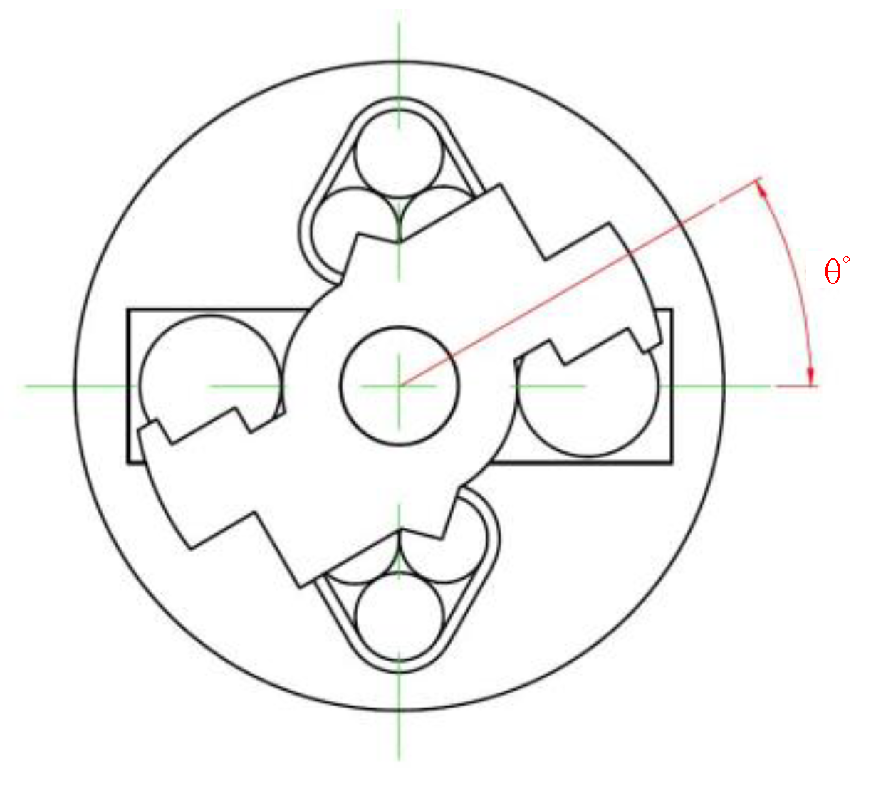
Energies 11 02772 g001
Figure 2. Coordinate and rotating angle of the single-phase switched reluctance motor.
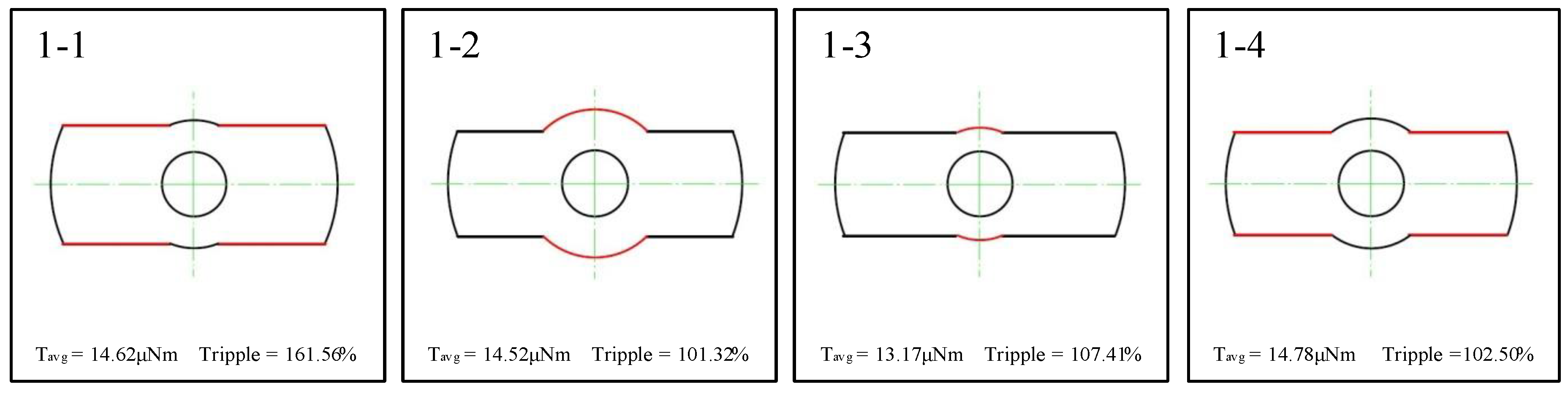
Energies 11 02772 g002
Figure 3. Step 1: Design process of the rotor magnetic pole width and root diameter.
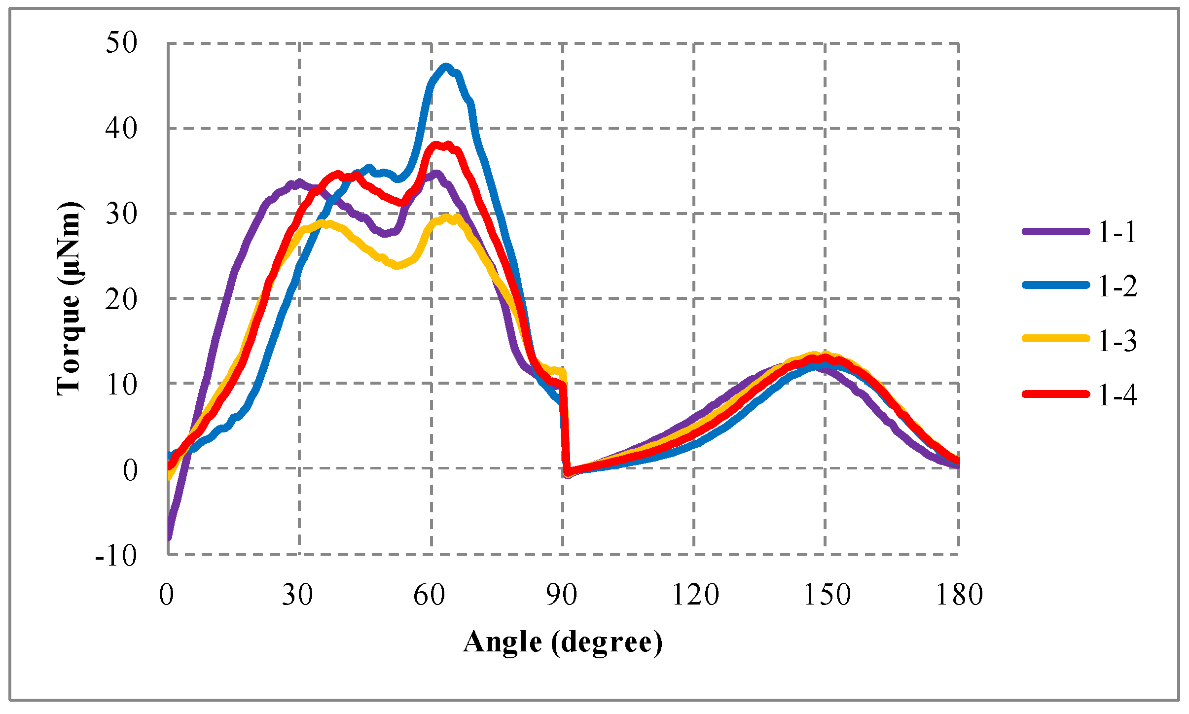
Energies 11 02772 g003
Figure 4. Step 1: Torque-angle curve for each step.
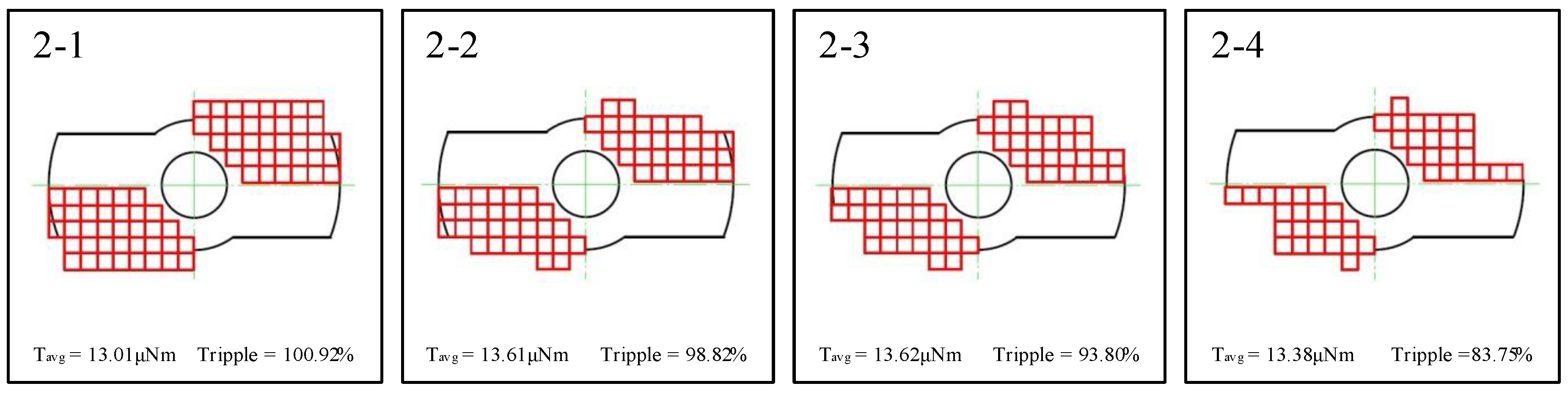
Energies 11 02772 g004
Figure 5. Step 2: Design process of the rotor magnetic pole of quadrants 1 and 3.
Energies 11 02772 g005
Figure 6. Step 2: Torque-angle curve for each step.
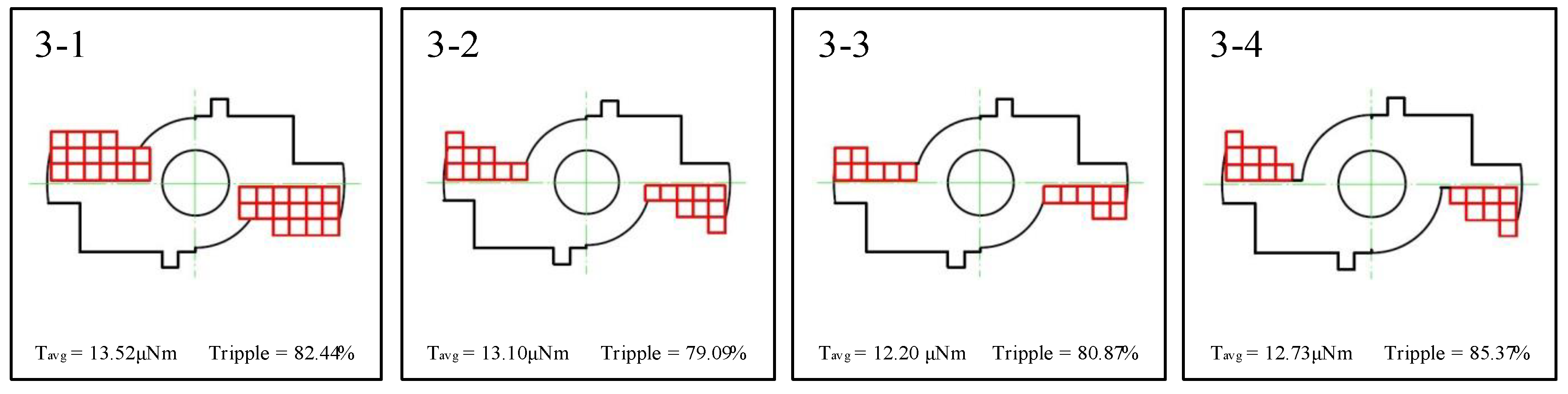
Energies 11 02772 g006
Figure 7. Step 3: Design process of the rotor magnetic poles for quadrant 2 and 4.
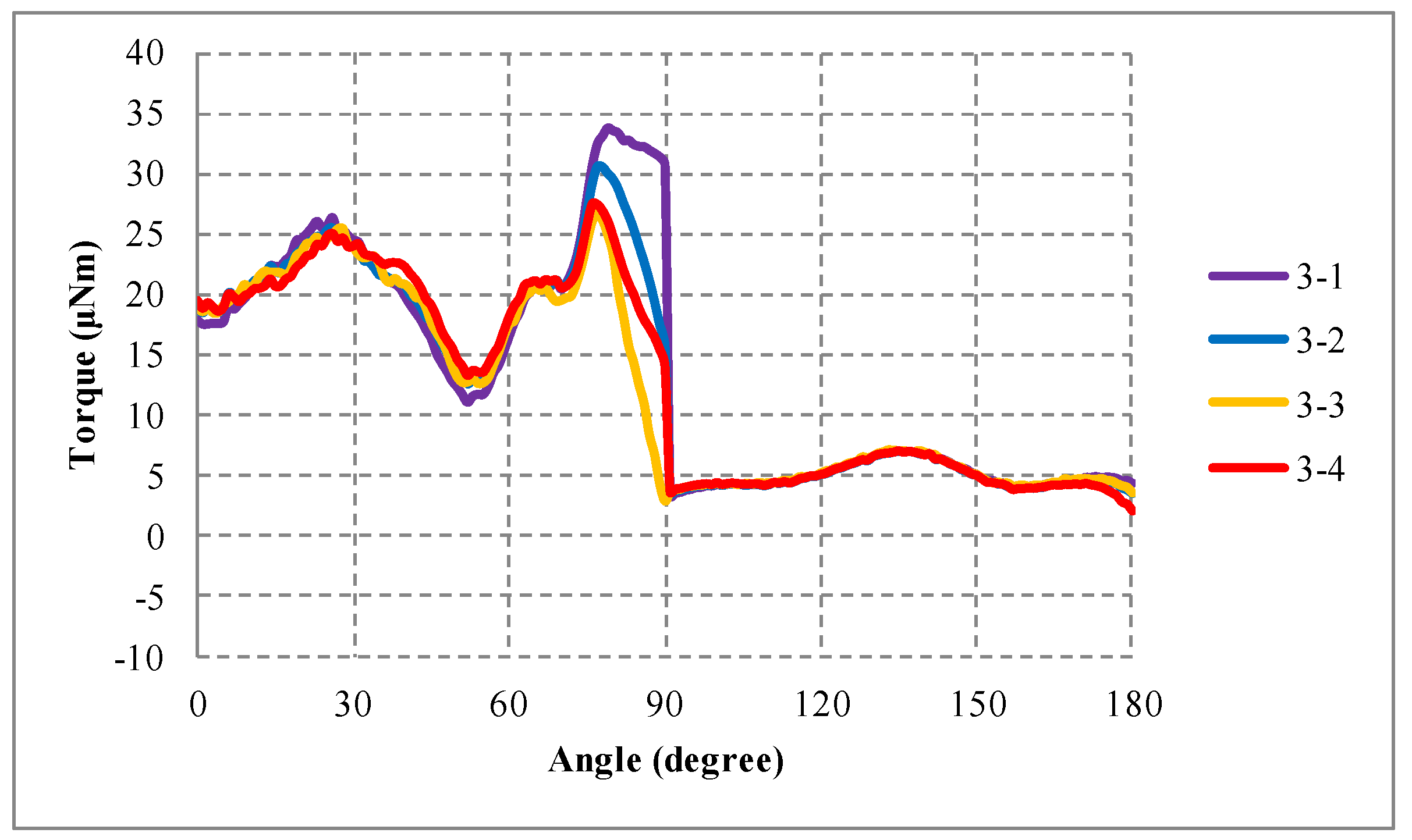
Energies 11 02772 g007
Figure 8. Step 3: Torque-angle curve for each step.
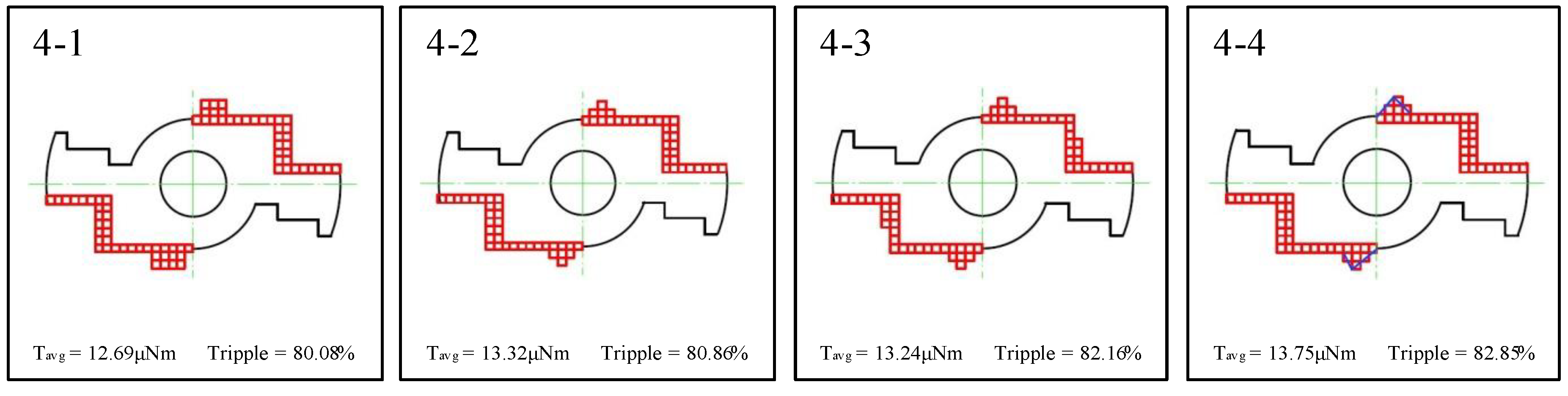
Energies 11 02772 g008
Figure 9. Step 4: Detailed design process of the rotor magnetic pole.
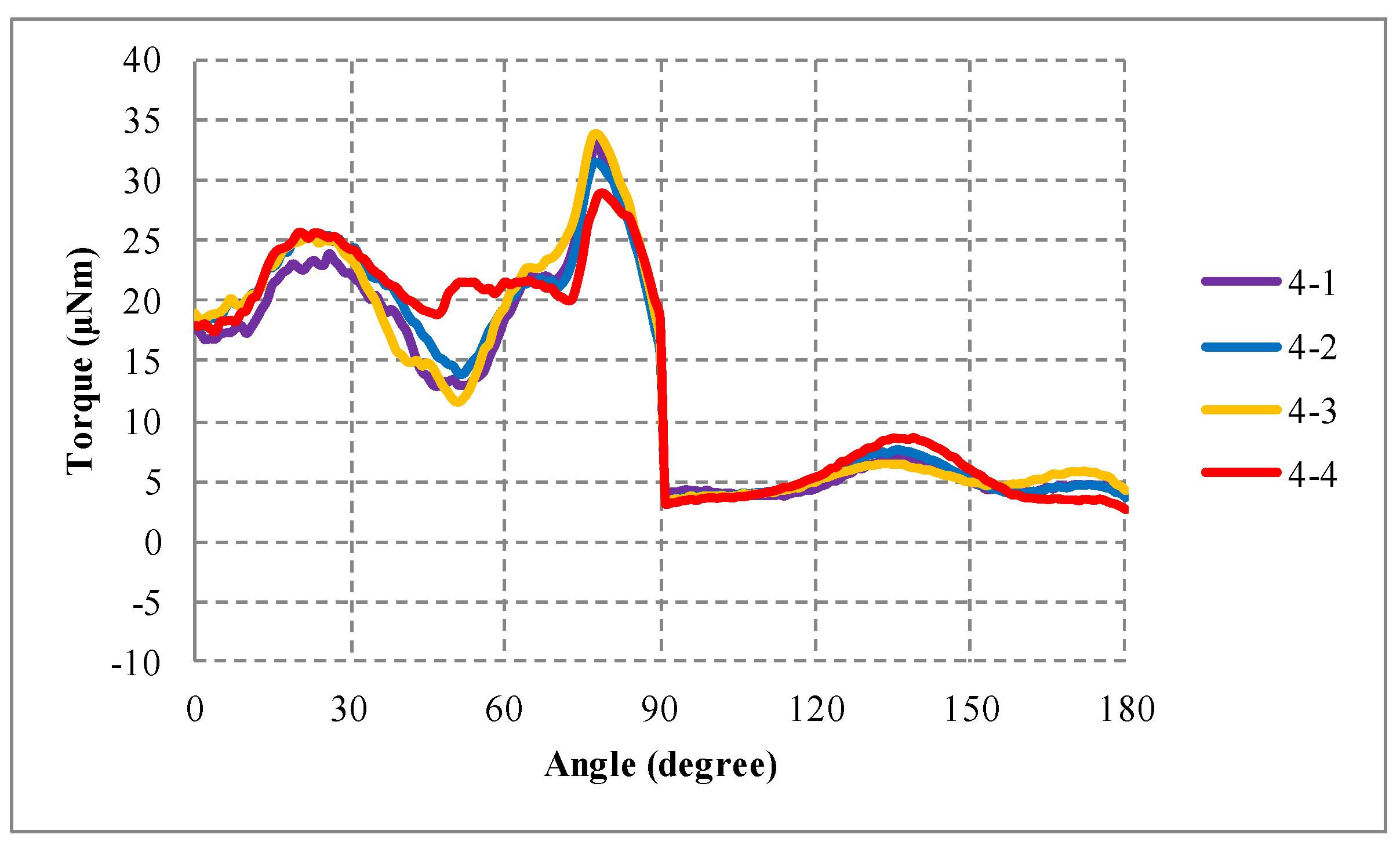
Energies 11 02772 g009
Figure 10. Step 4: Torque-angle curve for each step.
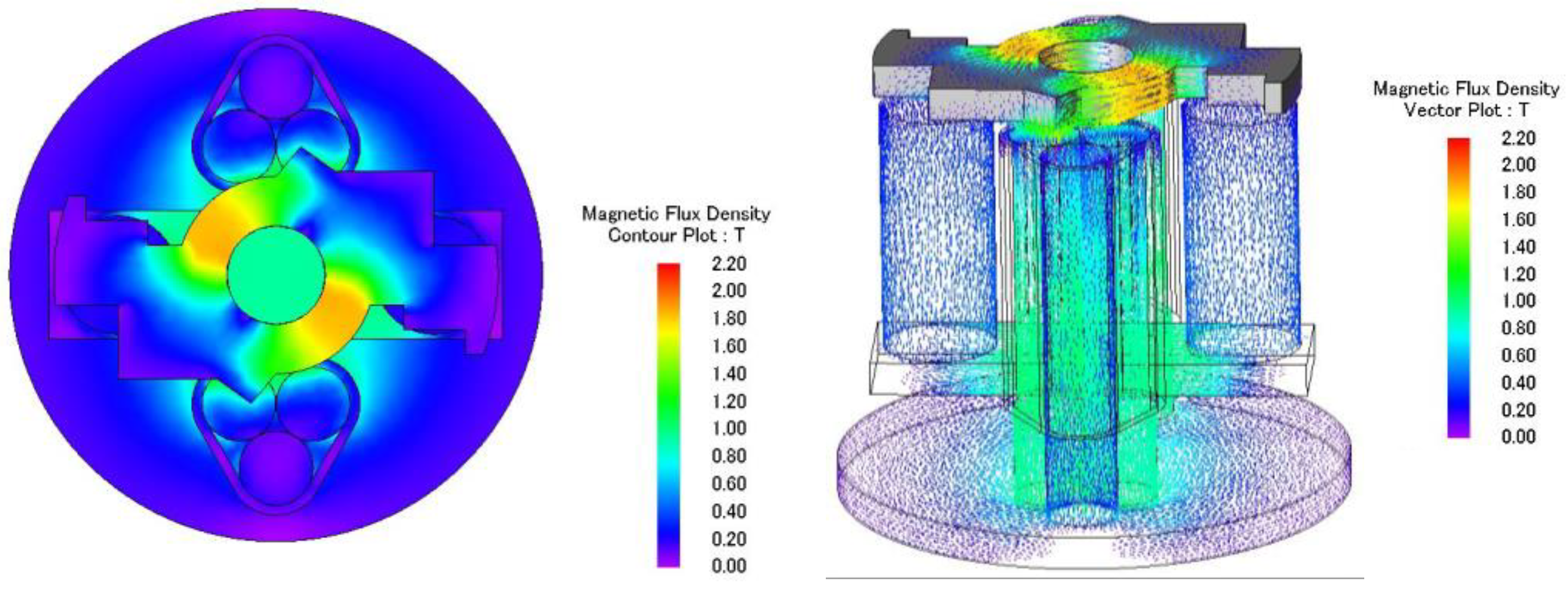
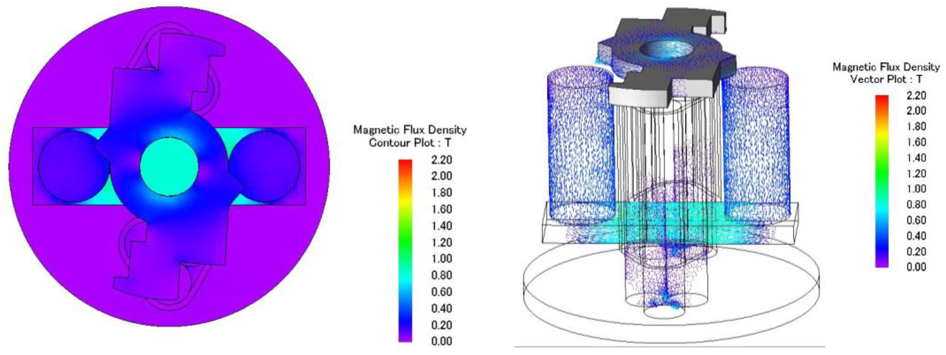
Energies 11 02772 g010
Figure 11. Top view and 3D view of magnetic flux density plots of the motor at a rotating angle of 0°.
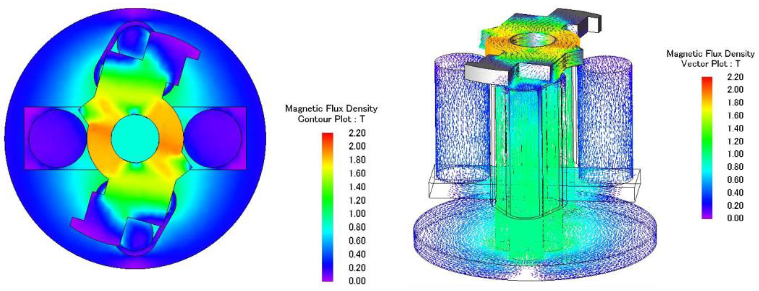
Energies 11 02772 g011
Figure 12. Top view and 3D view of magnetic flux density plots of the motor at a rotating angle of 74°.
Energies 11 02772 g012
Figure 13. Top view and 3D view of magnetic flux density plots of the motor at a rotating angle of 91°.
Energies 11 02772 g013
Figure 14. Top view and 3D view of magnetic flux density plots of the motor at a rotating angle of 135°.
Energies 11 02772 g014
Figure 15. Mechanical parts of the axial-flux, single-phase switched reluctance motor.
Energies 11 02772 g015
Figure 16. Prototype of the axial-flux, single-phase switched reluctance motor.
Energies 11 02772 g016
Figure 17. Theoretical and experimental torque-angle curves of the single-phase switched reluctance motor.
Energies 11 02772 g017
Figure 18. Theoretical and experimental torque-angle curves of the motor with friction correction.
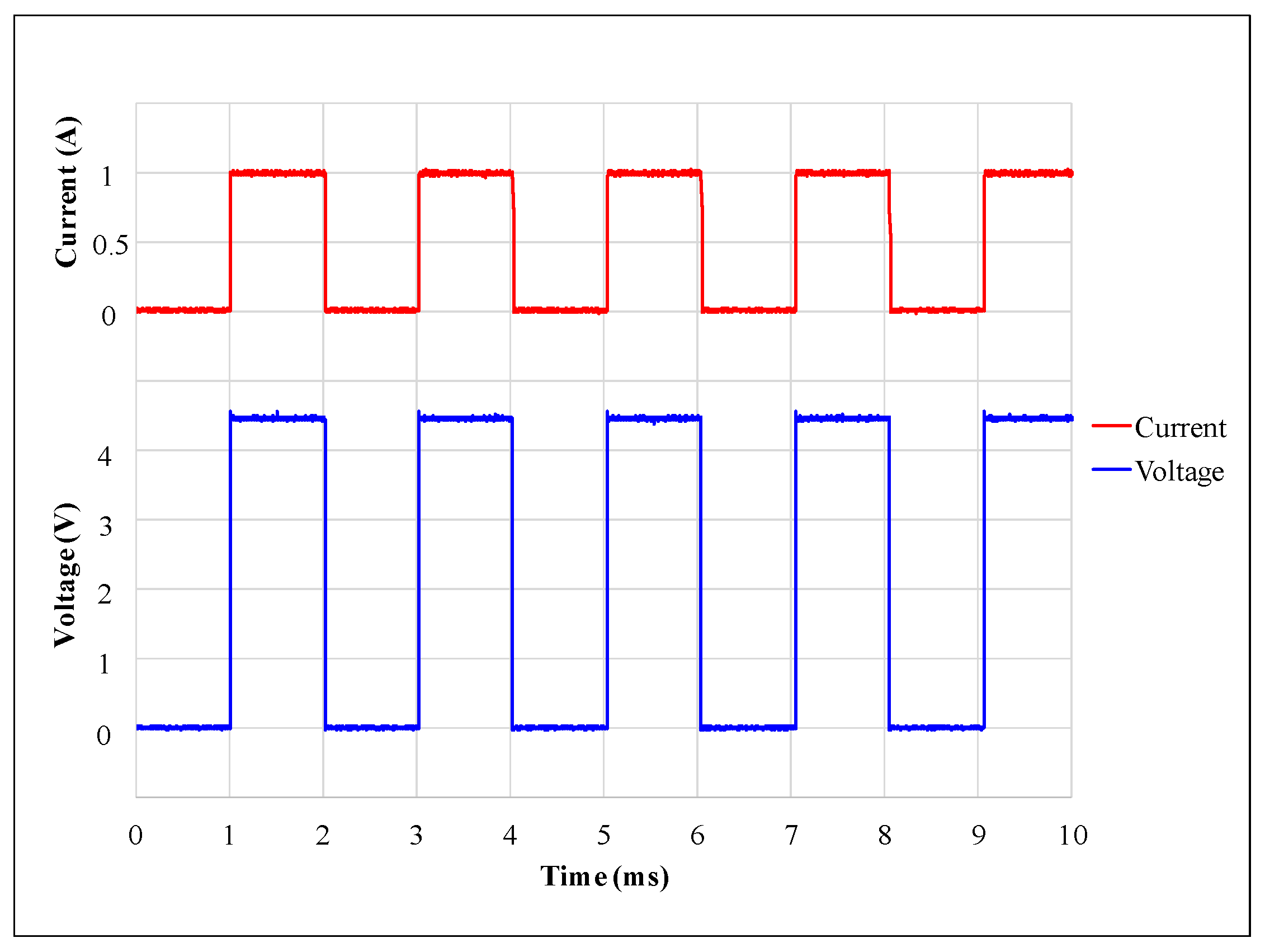
Energies 11 02772 g018
Figure 19. Voltage and current signals of the single-phase switched reluctance motor at a maximum speed of 1500 rpm.
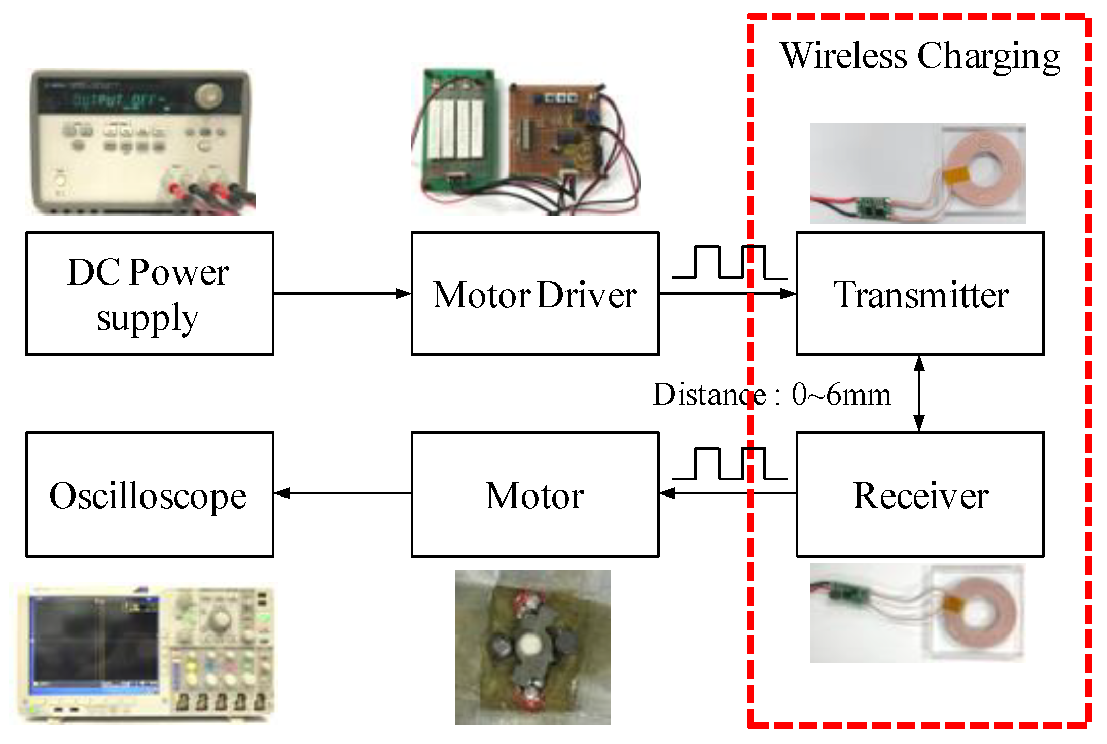
Energies 11 02772 g019
Figure 20. Schematic diagram of the wireless-driven, single-phase switched reluctance motor system.
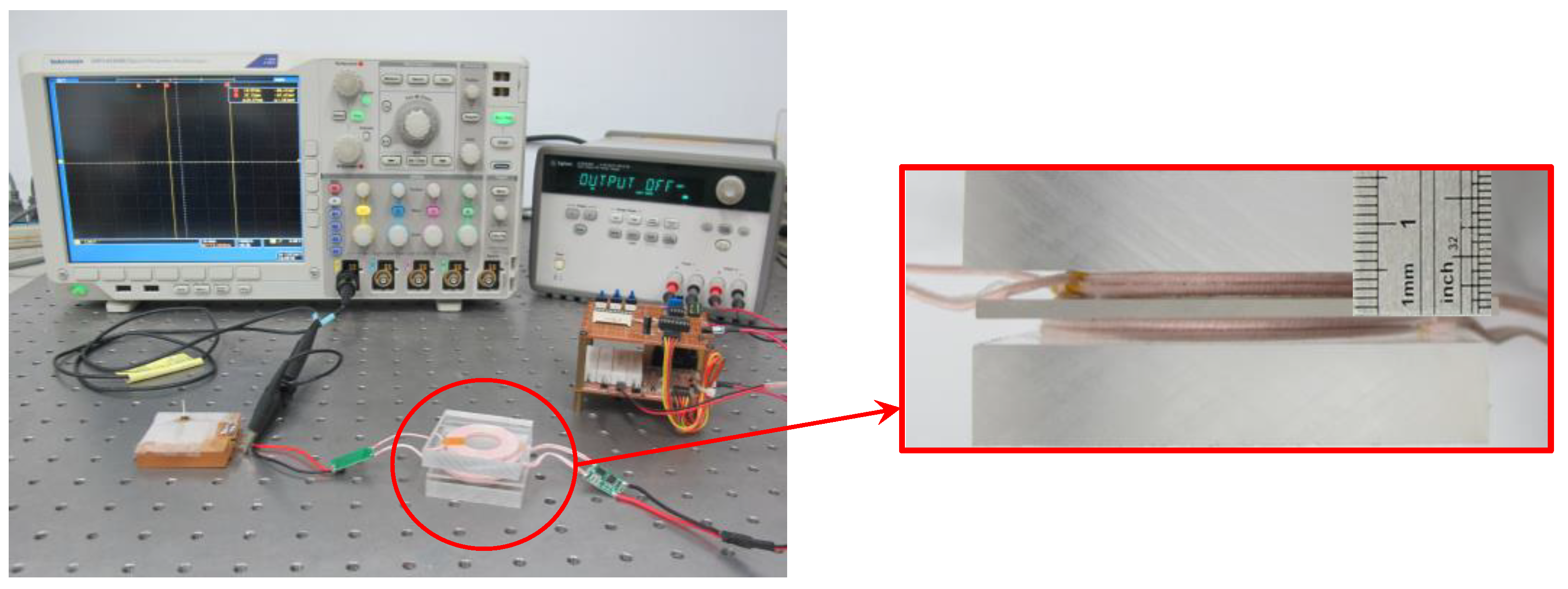
Energies 11 02772 g020
Figure 21. Photograph of the actual wireless-driven, single-phase switched reluctance motor test system.
Energies 11 02772 g021
Figure 22. Current-distance curves of the single-phase switched reluctance motor and pure resistance loads.
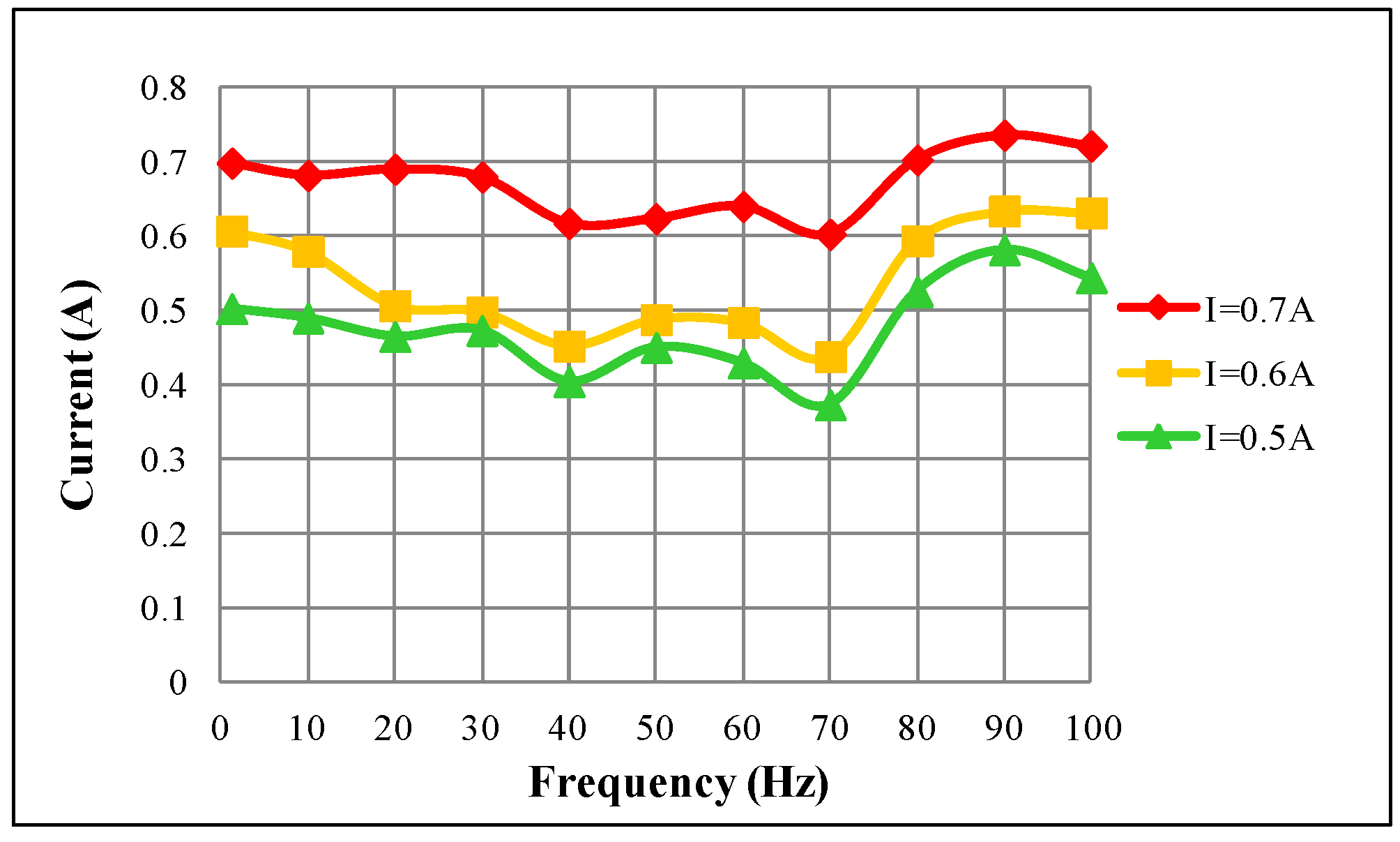
Energies 11 02772 g022
Figure 23. Current-frequency curves of the wireless charging module with pure resistance loads at a 2 mm distance.
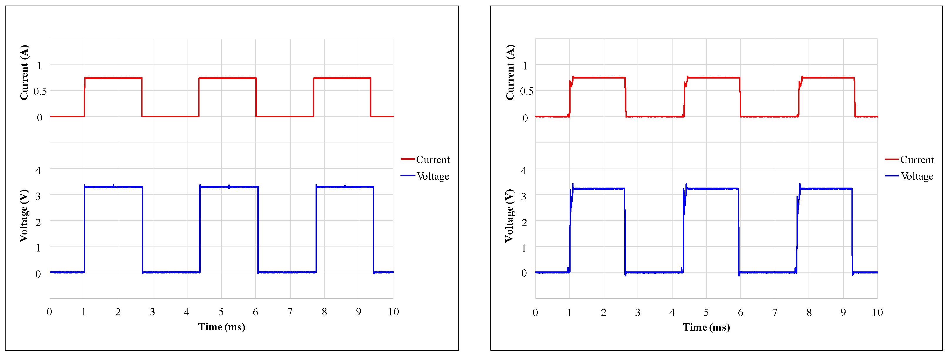
Energies 11 02772 g023
Figure 24. Voltage and current signals of the motor at 900 rpm with wire-driven (left) and wireless-driven (right) conditions.
Energies 11 02772 g024
Table 1. Specifications of the micro, axial-flux, single-phase switched reluctance motor.
Mechanical Specifications
StatorPoles2RotorPoles2
Number of permanent magnets2External diameter4.5 mm
External diameter5.5 mmRoot diameter2 mm
Diameter of magnetic rods0.75 mm × 3Internal diameter1 mm
Diameter of permanent magnets1.2 mmLength0.35 mm
Length of magnetic rods4 mmAir gap between rotor and stator pole0.06 mm
Length of permanent magnets2.65 mmAir gap between rotor and permanent magnet0.2 mm
Electrical Specifications
Phase1Step angle90°
Number of turns of coil120Diameter of coil0.07 mm
Maximum current1 AResistance of coil3.4 Ω
Table 2. Step 1: Comparison of the torque characteristics of each step.
Step1-11-21-31-4
Maximum torque (μN·m)34.5247.0729.3738.11
Minimum torque (μN·m)−8.12−0.31−1.05−0.47
Average torque (μN·m)14.6214.5213.1714.78
Relative ripple torque (%)161.56101.32107.41102.50
Table 3. Step 2: Comparison table of the torque characteristic of each step.
Step2-12-22-32-4
Maximum torque (μN·m)28.0729.5028.1434.21
Minimum torque (μN·m)−0.130.180.903.03
Average torque (μN·m)13.0113.6113.6213.38
Relative ripple torque (%)100.9298.8293.8083.75
Table 4. Step 3: Comparison of the torque characteristics of each step.
Step3-13-23-33-4
Maximum torque (μN·m)33.8730.6826.7727.40
Minimum torque (μN·m)3.263.582.832.16
Average torque (μN·m)13.5213.1012.2012.73
Relative ripple torque (%)82.4479.0980.8785.37
Table 5. Step 4: Comparison of the torque characteristics of each step.
Step4-14-24-34-4
Maximum torque (μN·m)33.2631.5333.9029.04
Minimum torque (μN·m)3.683.343.322.72
Average torque (μN·m)12.6713.3213.2413.75
Relative ripple torque (%)80.0880.8682.1682.85
Table 6. Comparisons of theoretical and experimental torque characteristics of the single-phase switched reluctance motor.
Current (A)Max. Torque (μN·m)Min. Torque (μN·m)Average Torque (μN·m)Relative Ripple Torque (%)
TheoryExperimentTheoryExperimentTheoryExperimentTheoryExperiment
0.512.039.261.981.545.654.2971.7771.43
0.615.3711.692.721.927.335.5669.8967.23
0.718.7514.332.721.928.996.7774.6472.45
0.822.2016.982.721.9210.628.0178.1576.23
0.925.6119.402.721.9212.219.2680.7878.89
129.0421.392.721.9213.7510.3482.8580.66
Table 7. Torque characteristics of the single-phase switched reluctance motor with and without friction correction.
Current (A)Maximum Torque (μN·m)Average Torque (μN·m)
TheoryExperiment without CorrectionExperiment with CorrectionTheoryExperiment without CorrectionExperiment with Correction
0.512.039.2610.455.654.295.48
0.615.3711.6912.887.335.566.75
0.718.7514.3315.528.996.777.96
0.822.2016.9818.1710.628.019.20
0.925.6119.4020.5912.219.2610.45
129.0421.3921.5813.7510.3411.53
Table 8. Time response comparisons of the wire- and wireless-driven, single-phase switched reluctance motors.
Speed (rpm)Driven MethodStable Time (ms)Rise Time (ms)Lag Time (ms)
900Wire-driven0.100.080.05
Wireless-driven1.260.860.54

