Iterative Method for Determining the Values of the Susceptances of a Balancing Capacitive Compensator


Abstract
:1. Introduction
2. New Equations for Initial Sizing of a BRC
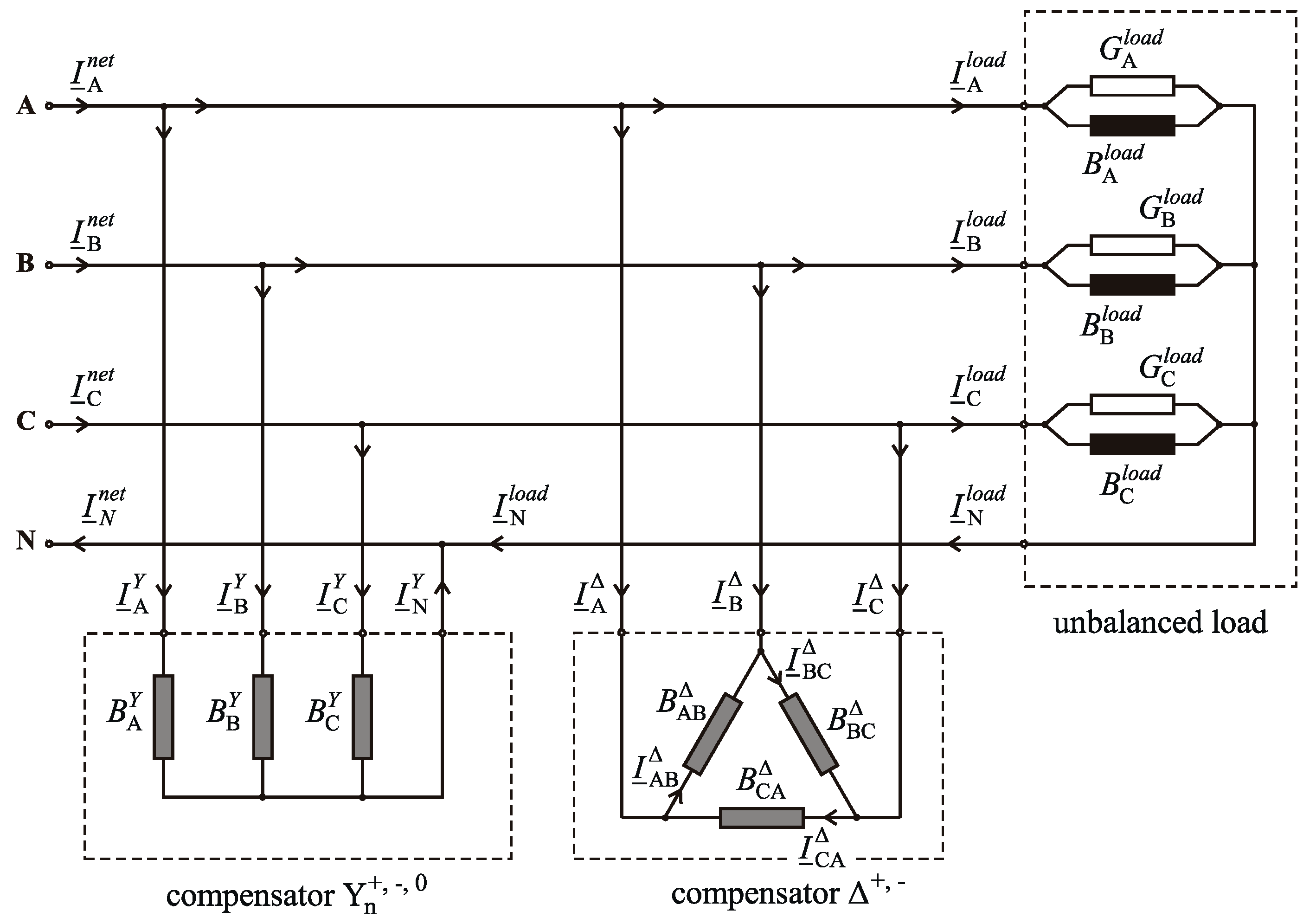
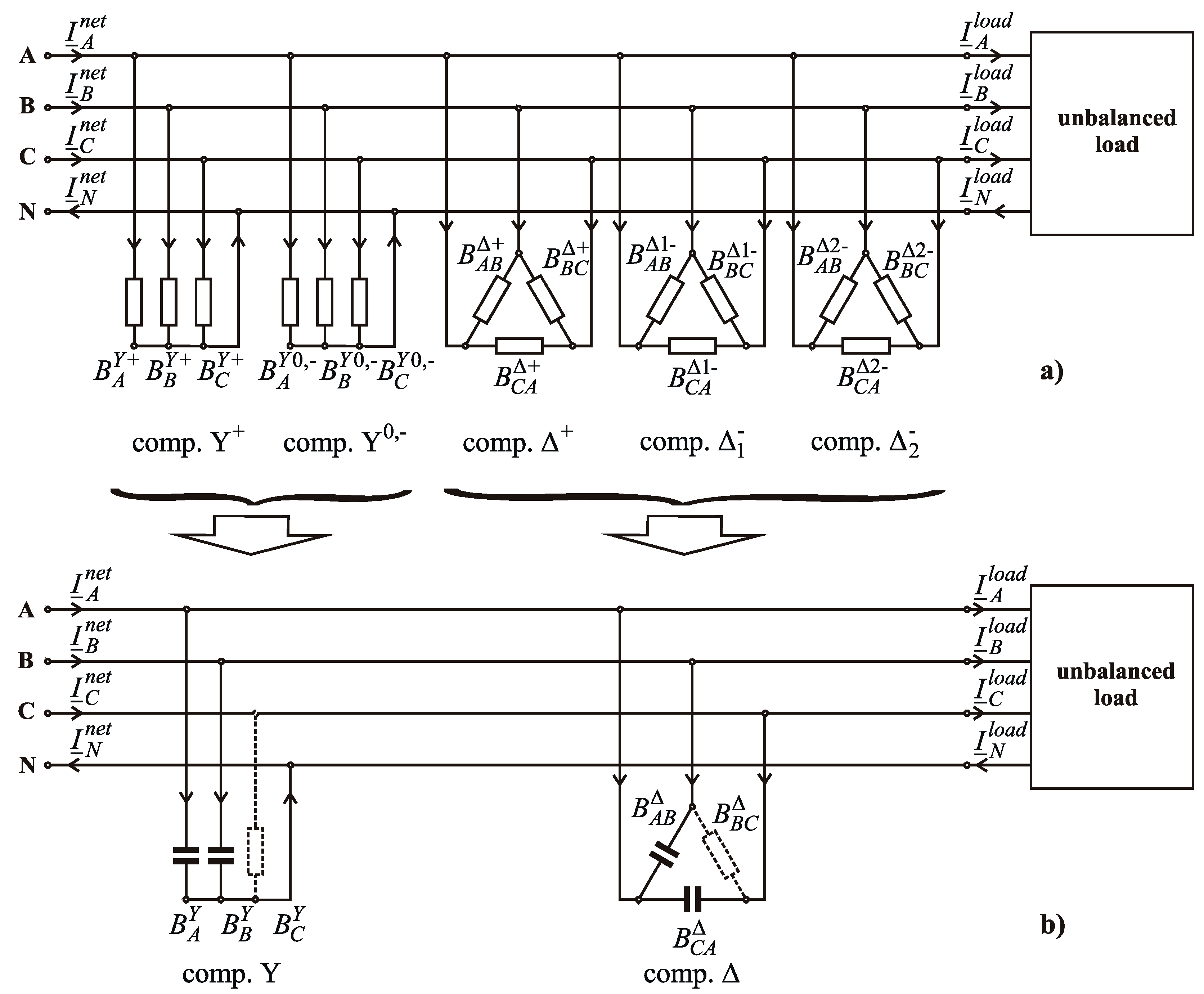
- one of positive sequence, which cancels (totally compensates) the imaginary (reactive) components of the positive sequence currents of the load;
- one of negative sequence, which cancels (totally compensates) a part of the negative sequence components on the Δ compensator phases; and
- one of zero sequence, which cancels (totally compensates) the zero sequence components of the load currents.
- a main one, which cancels (totally compensates) the negative sequence of the load currents; and
- a secondary one, which cancels (totally compensates) the negative sequence of the currents from the Yn compensator phases.
- compensator, which compensates the imaginary (reactive) components of the load positive sequence currents;
- compensator, which compensates the zero sequence components of the load currents and the negative sequence components of the currents on the compensator phases;
- compensator, which compensates the negative sequence components of the load currents; and
- compensator, which compensates the negative sequence components of the currents on the compensator phases.
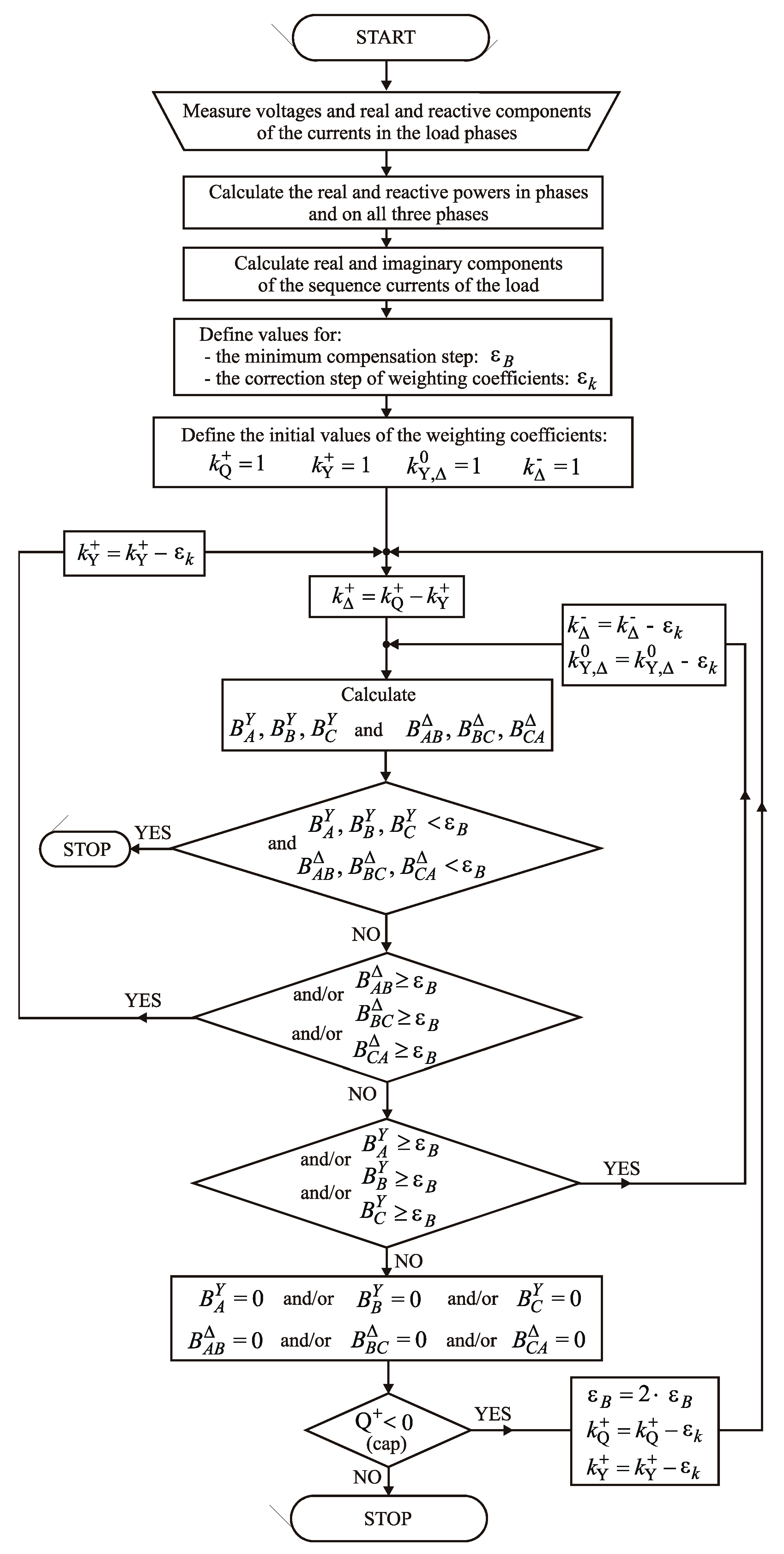
3. Resizing the BRC for Converting It into a BCC
- determines weighing of the component to determining the values of , , snf susceptances.
- determines weighing of the and components to determining the values of , , and susceptances.
- determines weighing of the and components to determining the values of , , and , and , , and susceptances, respectively.
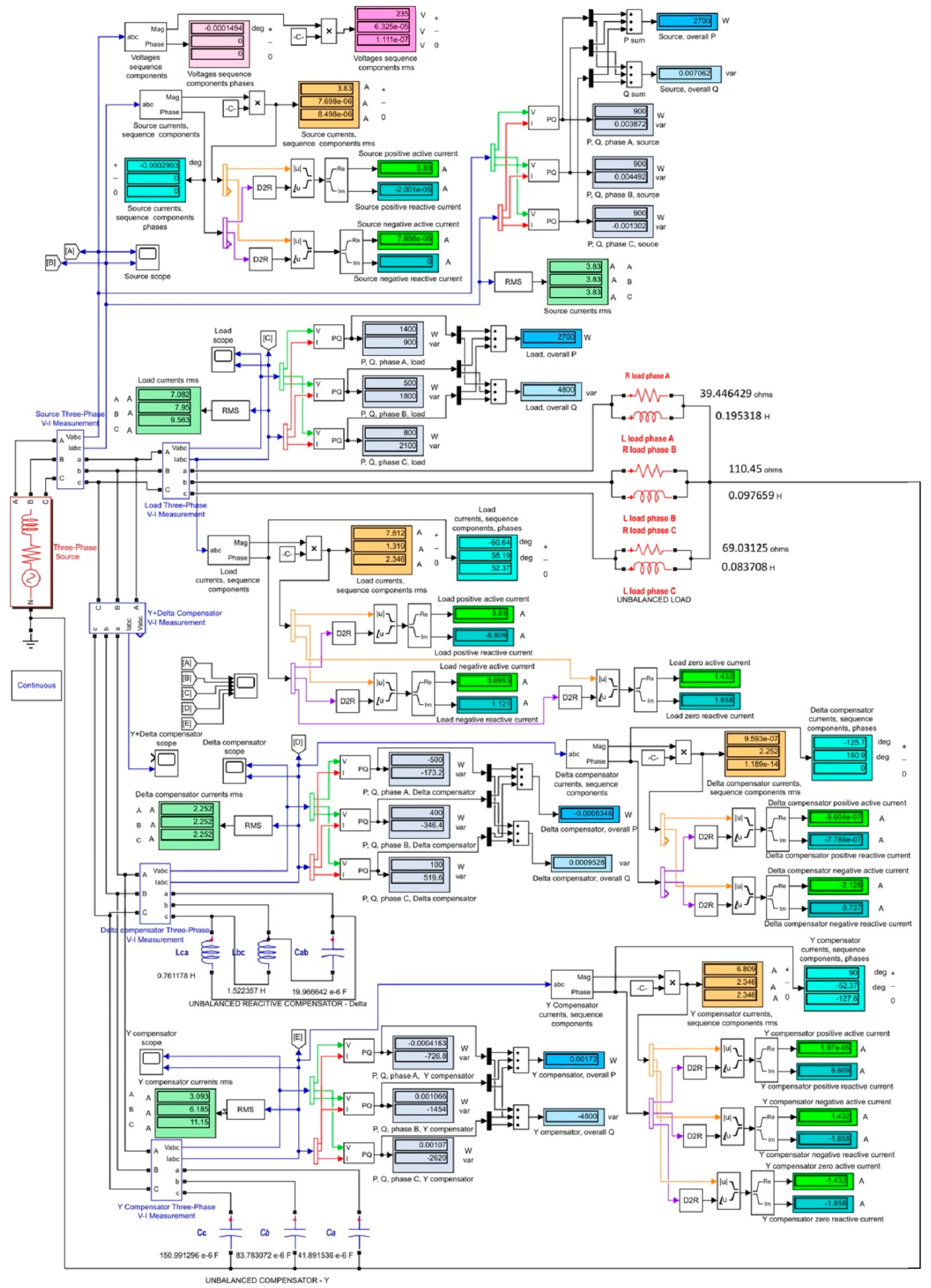
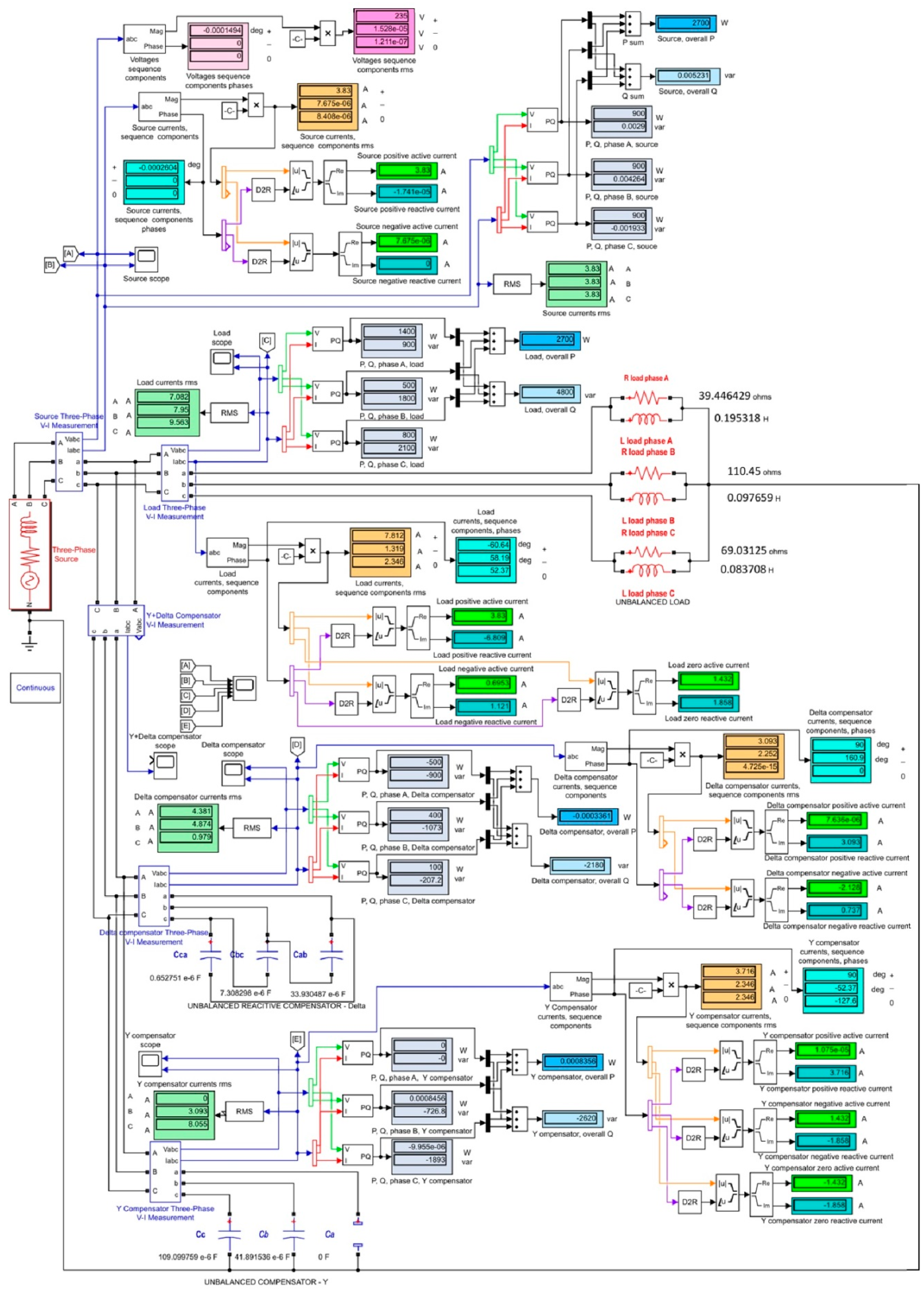
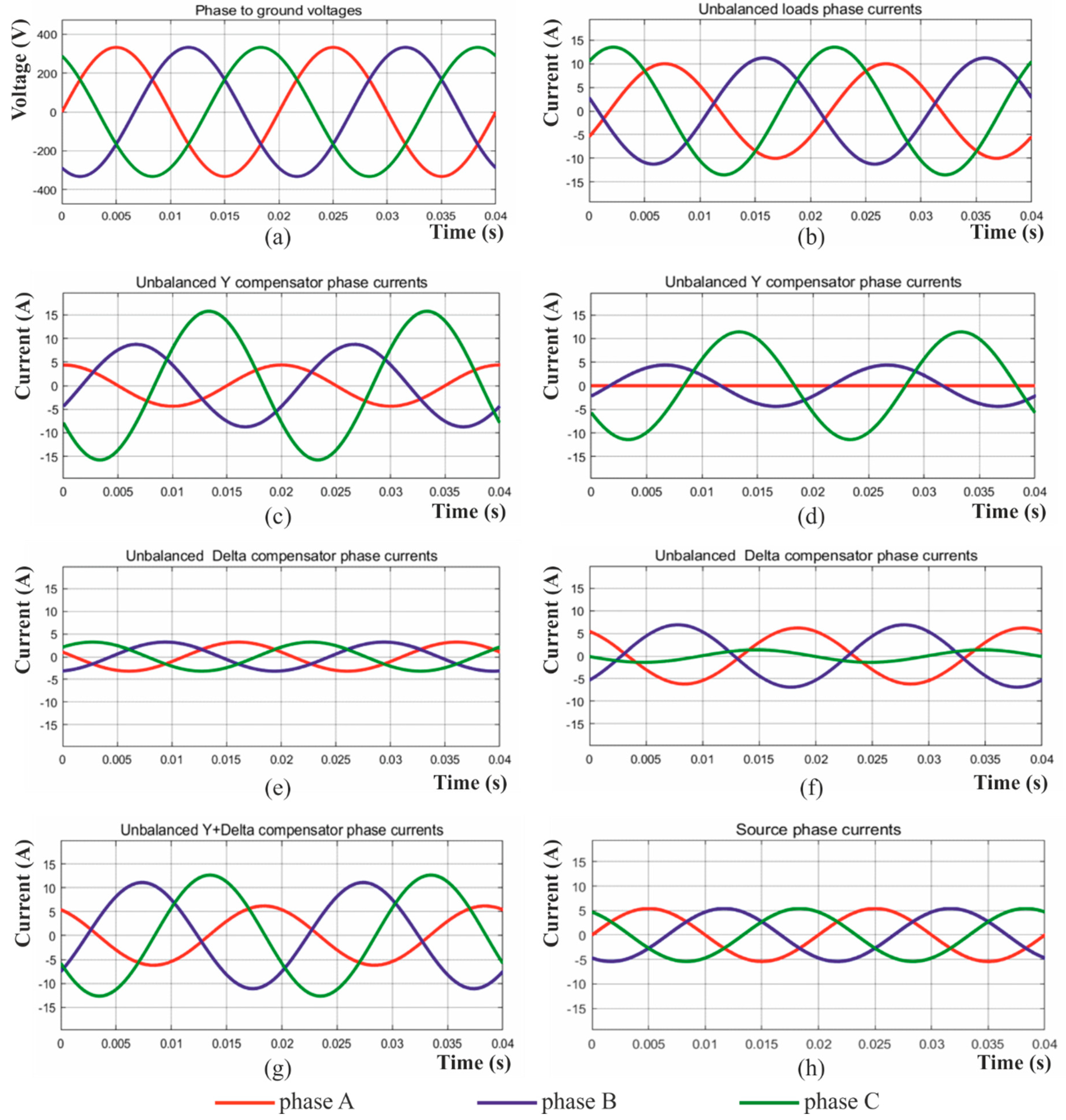
4. Case Study
- The power supply network is considered an ideal one, providing a perfectly symmetrical and sinusoidal three-phase voltages set, so that the unbalance will occur only in currents.
- The circuit elements of type R, L, and C are considered ideal, perfectly linear.
- The impedances of the connections between the circuit elements or the impedance of the neutral conductor are not considered.
- The Yn compensator acts exclusively on the reactive power flow on each phase, in both sizing versions. Containing only capacities, the Yn compensator provides reactive power;
- In the initial sizing variant, the Yn compensator provides the capacitive reactive power required to completely compensate the inductive reactive power of the load on the positive sequence, while in the resized variant, this function is shared with the Δ compensator; The Yn compensator acts only on the reactive power flow on each phase, in both sizing variants. Containing only capacities, the Yn compensator provides reactive power;
- In the initial sizing variant, the Yn compensator provides the capacitive reactive power required to completely compensate the inductive reactive power of the load on the positive sequence, while in the resized variant, this function is shared with the Δ compensator;
- The Δ compensator resulted from the initial sizing (BRC), makes a redistribution of the active and reactive powers between the circuit phases, without changing their total on the three phases. It is also confirmed the sizing hypothesis according to which it acts only in the negative sequence currents flowing;
- The Δ compensator in both versions contains only reactive passive elements, but also acts on the active power flow on the network phases: takes active power on the B and C phases and it delivers it back on the A phase. On the whole of the three phases the active power flow is not affected;
- In both variants, the Δ compensator identically acts on the active power flow, which is the effect of the fact that it identically acts on the negative sequence currents flowing;
- In both variants, the compensator assembly (Yn + Δ) has the same effect: completely compensates the five undesired components of the load sequence currents.
5. Conclusions
Author Contributions
Funding
Conflicts of Interest
Abbreviations and Notations
| PCC | Point of Common Coupling |
| RPC | Reactive Power Compensator |
| SVC | Static var Compensator |
| ABC | Adaptive Balancing Compensator |
| ABCC | Adaptive Balancing Capacitive Compensator |
| BRC | Balancing Reactive Compensator |
| BCC | Balancing Capacitive Compensator |
| SPC | Switching Power Converter |
| TCR | Thyristor Controlled Reactor |
| TSC | Thyristor Switched Capacitor |
| CSC | Contactor Switched Capacitor |
| IGBT | Insulated Gate Bipolar Transistor |
| IGCT | Integrated Gate Commutated Thyristor |
| SSD | Solid State Device |
| CPD | Custom Power Device |
| D-STATCOM | Distribution Static Synchronous Compensator |
| DVR | Dynamic Voltage Restorer |
| UPQC | Unified Power Quality Conditioner |
| VSI | Voltage Source Inverter |
| TSSPC | Thyristor Switched Single Phase Capacitor |
| CSSPC | Contactor Switched Single Phase Capacitor |
| , , | phasors of symmetrical components of the phase currents at the network (in PCC) |
| , , | phasors of symmetrical components of the phase currents at the load |
| , , | phasors of symmetrical components of the phase currents at Yn compensator |
| , , | phasors of the phase currents at Yn compensator |
| , , | rms values of the compensation currents at Yn compensator |
| , , | phasors of symmetrical components of the phase currents at Δ compensator |
| , , | phasors of the phase currents at Δ compensator |
| , , | phasors of the currents on Δ compensator branches |
| , , | rms values of the compensation currents on Δ compensator branches |
| rms value of phase to neutral voltages | |
| , , , | phasors of the currents on the network conductors (in PCC) |
| , , , | phasors of the currents on the load conductors |
| , , | load admittances for Yn equivalent circuit |
| , , , , , | load equivalent conductances and susceptances |
| , , | equivalent susceptances of Yn compensator |
| , , | equivalent susceptances of Δ compensator |
| a | Stokvis rotation operator |
| PF | power factor |
References
- Dugan, R.C.; McGranaghan, M.F.; Beaty, H.W. Electric Power Systems Quality, 2nd ed.; McGraw-Hill Education: New York, NY, USA, 2006; ISBN 978-0071386227. [Google Scholar]
- Antonio, M.M. Power Quality: Mitigation Technologies in a Distributed Environment; Springer: London, UK, 2007; ISBN 978-1-84628-772-5. [Google Scholar]
- Ewald, F.F.; Mohammad, A.S.M. Power Quality in Power Systems and Electrical Machines; Elsevier Academic Press: London, UK, 2008; ISBN 978-0-08-055917-9. [Google Scholar]
- Steinmetz, C.P. Theory and Calculation of Electrical Apparatus; McGraw Hill Book Company: New York, NY, USA, 1917. [Google Scholar]
- Grandpierr, M.; Trannoy, B. A stationary power device to rebalance and compensate reactive power in three-phase network. In Proceedings of the 1977 IAS Annual Conference, Los Angeles, CA, USA, 2–6 October 1977; pp. 127–135. [Google Scholar]
- Gyugyi, L.; Otto, R.; Putman, T. Principles and applications of static thyristor-controlled shunt compensators. IEEE Trans. Power Appl. Syst. 1935, PAS-97, 1935–1945. [Google Scholar] [CrossRef]
- Miller, J.E. Reactive Power Control in Electric Systems; John Wiley & Sons: New York, NY, USA, 1982. [Google Scholar]
- Gueth, G.; Enstedt, P.; Rey, A.; Menzies, R.W. Individual phase control of a static compensator for load compensation and voltage balancing. IEEE Power Eng. Rev. 1987, 2, 898–905. [Google Scholar] [CrossRef]
- Czarnecki, L.S. Reactive and unbalanced currents compensation in three-phase asymmetrical circuits under nonsinusoidal conditions. IEEE Trans. Instrum. Meas. 1989, 38, 754–759. [Google Scholar] [CrossRef]
- Czarnecki, L.S. Minimization of unbalanced currents in three-phase asymmetrical circuits with nonsinusoidal voltage. IEE Proc. B Electr. Power Appl. 1992, 139, 347–354. [Google Scholar] [CrossRef]
- Lee, S.Y.; Wu, C.J. On-line reactive power compensation schemes for unbalanced three-phase four wire distribution systems. IEEE Trans. Power Deliv. 1993, 8, 1235–1239. [Google Scholar] [CrossRef]
- Czarnecki, L.S. Supply and loading quality improvement in sinusoidal power systems with unbalanced loads supplied with asymmetrical voltage. Arch. Elektrotech. 1994, 77, 169–177. [Google Scholar] [CrossRef]
- Czarnecki, L.S.; Hsu, S.M. Thyristor controlled susceptances for balancing compensators operated under nonsinusoidal conditions. IEE Proc. Electr. Power Appl. 1994, 141, 177–185. [Google Scholar] [CrossRef]
- Czarnecki, L.S.; Hsu, S.M.; Chen, G. Adaptive balancing compensator. IEEE Trans. Power Deliv. 1995, 10, 1663–1669. [Google Scholar] [CrossRef]
- Oriega de Oliveira, L.C.; Barros Neto, M.C.; de Souza, J.B. Load compensation in four-wire electrical power systems. In Proceedings of the International Conference on Power System Technology, Perth, WA, Australia, 4–7 December 2000; pp. 1575–1580. [Google Scholar]
- Arendse, C.; Atkinson-Hope, G. Design of a Steinmetz Symmetrizer and application in unbalanced network. In Proceedings of the 45th International Universities Power Engineering Conference (UPEC2010), Cardiff, UK, 31 August–3 September 2010; pp. 1–6. [Google Scholar]
- Lee, S.-Y.; Wu, C.-J.; Chang, W.-N. A compact control algorithm for reactive power compensation and load balancing with static var compensator. Electr. Power Syst. Res. 2001, 58, 63–70. [Google Scholar] [CrossRef]
- Mayordomo, J.G.; Izzeddine, M.; Asensi, R. Load and voltage balancing in harmonic power flows by means of static var compensators. IEEE Trans. Power Deliv. 2002, 17, 761–769. [Google Scholar] [CrossRef]
- Grünbaum, L.; Petersson, A.; Thorvaldsson, B. FACTS improving the performance of electrical grids. In ABB Review (Special Report on Power Technologies); ABB Group: Zürich, Switzerland, 2003; pp. 13–18. [Google Scholar]
- Dixon, J.; Morán, L.; Rodríguez, J.; Domke, R. Reactive power compensation technologies, state of-the-art review. Proc. IEEE 2005, 93, 2144–2164. [Google Scholar] [CrossRef]
- Quintela, F.R.; Arevalo, J.M.G.; Redondo, R.C. Power analysis of static var compensators. Int. J. Electr. Power Energy Syst. 2008, 30, 376–382. [Google Scholar] [CrossRef]
- Said, I.K.; Pirouti, M. Neural network-based load balancing and reactive power control by static var compensator. Int. J. Comput. Electr. Eng. 2009, 1, 25–31. [Google Scholar] [CrossRef]
- Xu, Y.; Tolbert, L.M.; Kueck, J.D.; Rizy, D.T. Voltage and current unbalance compensation using a static var compensator. IET Power Electr. 2010, 3, 977–988. [Google Scholar] [CrossRef]
- Jeon, S.-J.; Willens, J.L. Reactive power compensation in multi-line systems under sinusoidal unbalanced conditions. Int. J. Circuit Theory Appl. 2011, 39, 211–224. [Google Scholar] [CrossRef]
- Pană, A.; Băloi, A.; Molnar-Matei, F. Experimental validation of power mechanism for load balancing using variable susceptances in three-phase four-wire distribution networks. In Proceedings of the International Conference on “Computer as a Tool”—EUROCON 2007, Warsaw, Poland, 9–12 September 2007; pp. 1567–1572. [Google Scholar]
- Pană, A.; Băloi, A.; Molnar-Matei, F. Load balancing by unbalanced capacitive shunt compensation—A numerical approach. In Proceedings of the 14th International Conference on Harmonics and Quality of Power—ICHQP 2010, Bergamo, Italy, 26–29 September 2010; pp. 1–6. [Google Scholar]
- Pană, A. Active load balancing in a three-phase network by reactive power compensation. In Power Quality —Monitoring, Analysis and Enhancement; Zobaa, A., Ed.; InTech: Rijeka, Croatia, 2011; pp. 219–254. [Google Scholar]
- Sun, Q.; Zhou, J.; Liu, X.; Yang, J. A novel load-balancing method and device by intelligent grouping compound switches-based capacitor banks shunt compensation. Math. Probl. Eng. 2013, 2013, 11. [Google Scholar] [CrossRef]
- Hingorani, N.G.; Gyugyi, L. Understanding FACTS: Concepts and Technology of Flexible AC Transmission Systems; Wiley: Hoboken, NJ, USA, 2000. [Google Scholar]
- Lee, S.-Y.; Wu, C.-J. Reactive power compensation and load balancing for unbalanced three-phase four-wire system by a combined system of an svc and a series active filter. IEE Proc. Electr. Power Appl. 2000, 147, 563–578. [Google Scholar] [CrossRef]
- Haque, M.H. Compensation of distribution system voltage sag by DVR and DSTATCOM. In Proceedings of the IEEE Porto Power Tech Proceedings, Porto, Portugal, 10–13 September 2001; pp. 10–13. [Google Scholar]
- Wang, B.; Cathey, J.J. DSP—Controlled, Space-Vector PWM, Current Source Converter for STATCOM application. Electr. Power Syst. Res. 2003, 67, 123–131. [Google Scholar] [CrossRef]
- Dixon, J.; del Valle, Y.; Orchard, M.; Ortuzar, M.; Moran, L.; Maffrand, C. A full compensating system for general loads, based on a combination of thyristor binary compensator, and a PWM-IGBT active power filter. IEEE Trans. Ind. Electron. 2003, 50, 982–989. [Google Scholar] [CrossRef]
- Nguyen, P.T.; Saha, T.K. Dynamic voltage restorer against balanced and unbalanced voltage sags: Modeling and simulation. In Proceedings of the Power Engineering Society General Meeting, Denver, CO, USA, 6–10 June 2004; Volume 2. [Google Scholar]
- Nielsen, J.G.; Newman, M.; Nielsen, H.; Blaabjerg, F. Control and testing of a dynamic voltage restorer (DVR) at medium voltage level. IEEE Trans. Power Electron. 2004, 3, 806–813. [Google Scholar] [CrossRef]
- Mienski, R.; Pawelek, R.; Wasiak, I. Shunt compensation for power quality improvement using a STATCOM controller: Modeling and simulation. IEE Proc. Gener. Transm. Distrib. 2004, 274–280. [Google Scholar] [CrossRef]
- Pakdel, M.; Farzaneh-Fard, H. A control strategy for load balancing and power factor correction in three-phase four-wire systems using a shunt active power filter. In Proceedings of the IEEE International Conference on Industrial Technology (ICIT 2006), Mumbai, India, 15–17 December 2006; pp. 579–584. [Google Scholar]
- Akagi, H.; Fujita, H.; Yonetani, S.; Kondo, Y. A 6.6-kV transformerless STATCOM based on a five-level diode-clamped PWM converter: System design and experimentation of a 200-V, 10-kVA laboratory model. IEEE Trans. Ind. Appl. 2008, 44, 672–680. [Google Scholar] [CrossRef]
- Singh, B.N.; Saha, R.; Chandra, A.; Al-Haddad, K. Static synchronous compensators (STATCOM): A review. IET Power Electron. 2009, 2, 297–324. [Google Scholar] [CrossRef]
- Mishra, M.K.; Karthikeyan, K. An investigation on design and switching dynamics of a voltage source inverter to compensate unbalanced and nonlinear loads. IEEE Trans. Ind. Electron. 2009, 56, 2802–2810. [Google Scholar] [CrossRef]
- Lee, W.C.; Lee, D.M.; Lee, T.K. New control scheme for a unified power-quality compensator-q with minimum active power injection 2010. IEEE Trans. Power Deliv. 2010, 25, 1068–1076. [Google Scholar] [CrossRef]
- Capitanescu, F.; Wehenkel, L. Redispatching active and reactive powers using a limited number of control actions. IEEE Trans. Power Syst. 2011, 26, 1221–1230. [Google Scholar] [CrossRef]
- Win, T.S.; Hiraki, E.; Okamoto, M.; Lee, S.R.; Tanaka, T. Constant DC capacitor voltage control based strategy for active load balancer in three-phase four-wire distribution system. In Proceedings of the 2013 International Conference on Electrical Machines and Systems (ICEMS), Busan, Korea, 26–29 October 2013; pp. 1560–1565. [Google Scholar]
- Fu, X.; Chen, H.; Mo, W. Dynamic voltage restorer based on active hybrid energy storage system. In Proceedings of the 2014 IEEE PES Asia-Pacific Power and Energy Engineering Conference (APPEEC), Hong Kong, China, 7–10 December 2014; pp. 1–4. [Google Scholar]
- Hingorani, N.G. Introducing custom power. IEEE Spectr. 1995, 32, 41–48. [Google Scholar] [CrossRef]
- Ghosh, A. Power Quality Enhancement Using Custom Power Devices; Springer: New York, NY, USA, 2002; ISBN 978-1-4020-7180-5. [Google Scholar]
- Crow, M.L. Power quality enhancement using custom power devices. IEEE Power Energy Mag. 2004, 2, 50. [Google Scholar] [CrossRef]
- Domijan, A., Jr.; Montenegro, A.; Kern, A.J.F.; Mattern, K.E. Custom power devices: An interaction study. IEEE Trans. Power Syst. 2005, 20, 1111–1118. [Google Scholar] [CrossRef]
- Gupt, S.; Dixit, A.; Mishra, N.; Singh, S.P. Custom power devices for power quality improvement: A review. Int. J. Res. Eng. Appl. Sci. 2012, 2, 1646–1659. [Google Scholar]
- Roncero-Sànchez, P.; Acha, E. Design of a control scheme for distribution static synchronous compensators with power-quality improvement capability. Energies 2014, 7, 2476–2497. [Google Scholar] [CrossRef]
- Hosseinzadeh, M.; Salmasi, F.R. Robust optimal power management system for a hybrid AC/DC micro-grid. IEEE Trans. Sustain. Energy 2015, 6, 675–687. [Google Scholar] [CrossRef]
- Farkoush, S.G.; Kim, C.-H.; Rhee, S.-B. THD reduction of distribution system based on ASRFC and HVC method for SVC under EV charger condition for power factor improvement. Symmetry 2016, 8, 156. [Google Scholar] [CrossRef]
- Tokiwa, A.; Yamada, H.; Tanaka, T.; Watanabe, M.; Shirai, M.; Teranishi, Y. New hybrid static var compensator with series active filter. Energies 2017, 10, 1617. [Google Scholar] [CrossRef]
- Xue, Y.; Zhang, X.P. Reactive power and AC voltage control of LCC HVDC system with controllable capacitors 2017. IEEE Trans. Power Syst. 2017, 32, 753–764. [Google Scholar] [CrossRef]
- Barrios-Martínez, E.; Ángeles-Camacho, C. Technical comparison of FACTS controllers in parallel connection. J. Appl. Res. Technol. 2017, 15, 36–44. [Google Scholar] [CrossRef]
- Pana, A.; Baloi, A.; Molnar-Matei, F. From the Balancing Reactive Compensator to the Balancing Capacitive Compensator. Energies 2018, 11, 1979. [Google Scholar] [CrossRef]


| Equivalent Parameters | Active Powers | Reactive Powers | Phase Currents | Sequence Currents |
|---|---|---|---|---|
| - | - |
| Compo-nent | Equivalent Parameters | Active Powers | Reactive Powers | Phase Currents | Sequence Currents |
|---|---|---|---|---|---|
| Yn | |||||
| - | |||||
| - | |||||
| - | - | - | |||
| Δ | |||||
| - | |||||
| - | |||||
| - | - | - |
| Compo-nent | Equivalent Parameters | Active Powers | Reactive Powers | Phase Currents | Sequence Currents |
|---|---|---|---|---|---|
| Y | |||||
| - | |||||
| - | |||||
| - | - | - | |||
| Δ | |||||
| - | |||||
| - | |||||
| - | - | - |
| Compo-nent | Equivalent Parameters | Real Powers | Reactive Powers | Phase Currents | Sequence Currents |
|---|---|---|---|---|---|
| Network (PCC) | |||||
| - | |||||
| - | |||||
| - | - | - |
© 2018 by the authors. Licensee MDPI, Basel, Switzerland. This article is an open access article distributed under the terms and conditions of the Creative Commons Attribution (CC BY) license (http://creativecommons.org/licenses/by/4.0/).
Share and Cite
Pană, A.; Băloi, A.; Molnar-Matei, F. Iterative Method for Determining the Values of the Susceptances of a Balancing Capacitive Compensator. Energies 2018, 11, 2742. https://doi.org/10.3390/en11102742
Pană A, Băloi A, Molnar-Matei F. Iterative Method for Determining the Values of the Susceptances of a Balancing Capacitive Compensator. Energies. 2018; 11(10):2742. https://doi.org/10.3390/en11102742
Chicago/Turabian StylePană, Adrian, Alexandru Băloi, and Florin Molnar-Matei. 2018. "Iterative Method for Determining the Values of the Susceptances of a Balancing Capacitive Compensator" Energies 11, no. 10: 2742. https://doi.org/10.3390/en11102742
APA StylePană, A., Băloi, A., & Molnar-Matei, F. (2018). Iterative Method for Determining the Values of the Susceptances of a Balancing Capacitive Compensator. Energies, 11(10), 2742. https://doi.org/10.3390/en11102742