Exploring the Interplay between CAD and FreeFem++ as an Energy Decision-Making Tool for Architectural Design


 ,
,  and
and
Abstract
1. Introduction
2. Energy Analysis Simulation Tools
2.1. ANSYS Fluent
2.2. DesignBuilder
2.3. Revit Autodesk (Formerly Ecotect Analysis)
2.4. SUNtool, Solene, RayMan, URSOS, and GreenCanyon.
2.5. EnergyPlus
2.6. ENVI-Met 3.1
2.7. FreeFem++
3. Geometries and Meshing
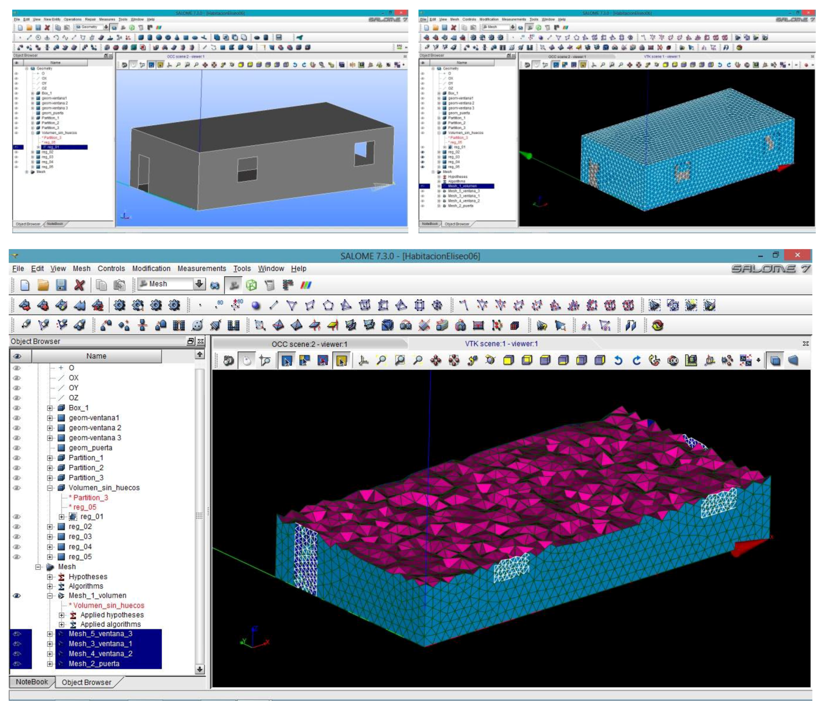
3.1. Salome Analysis
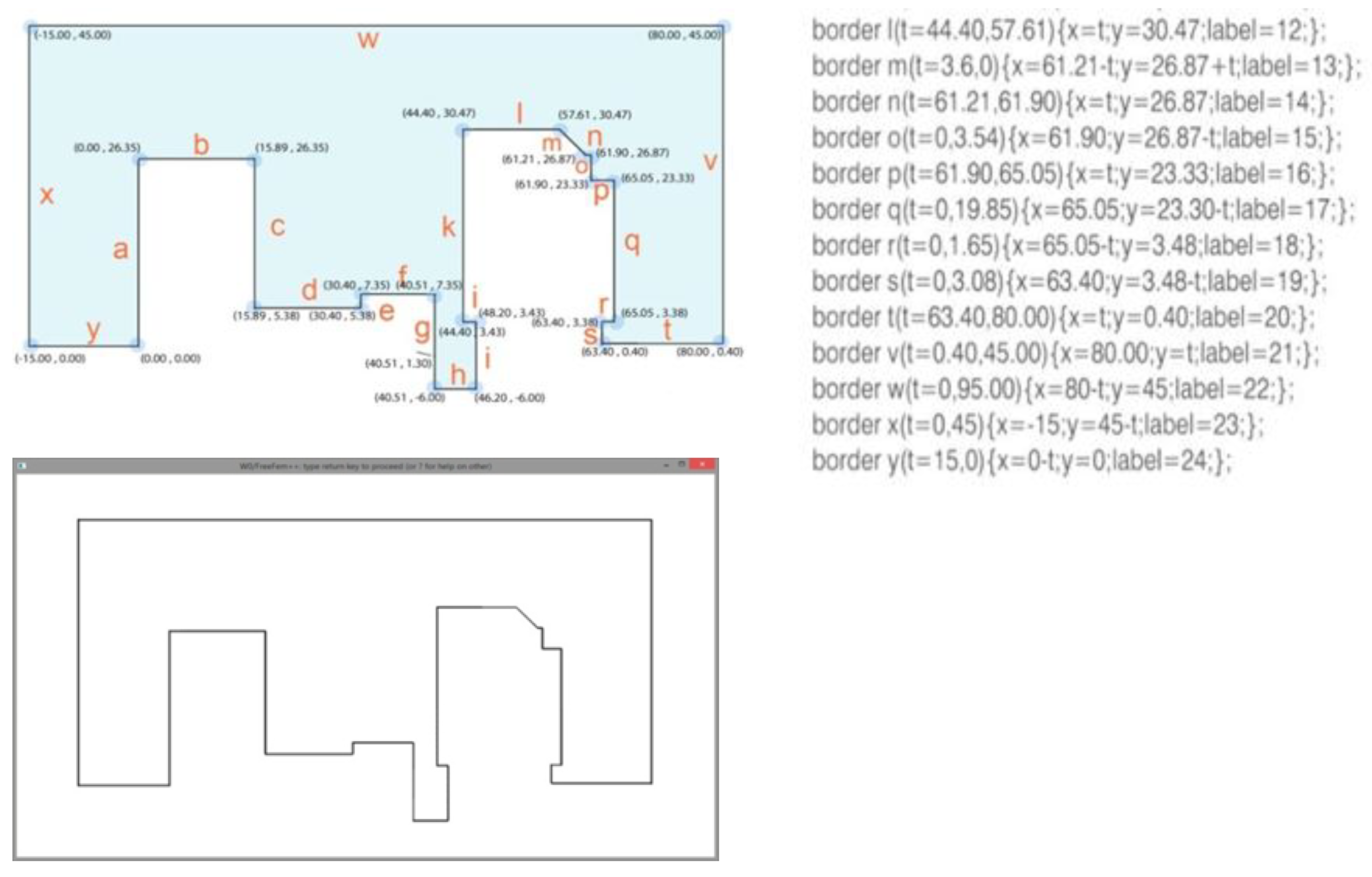
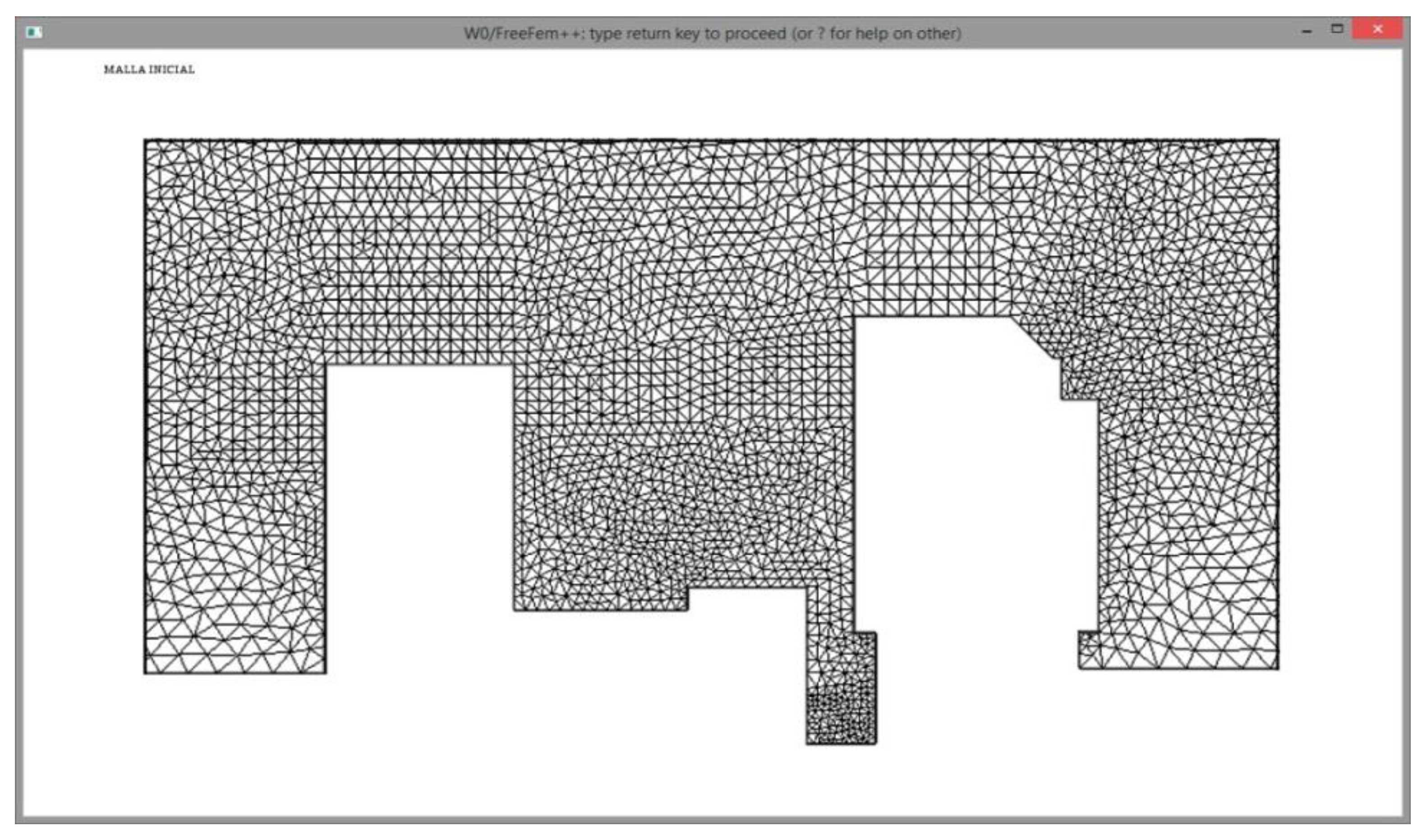
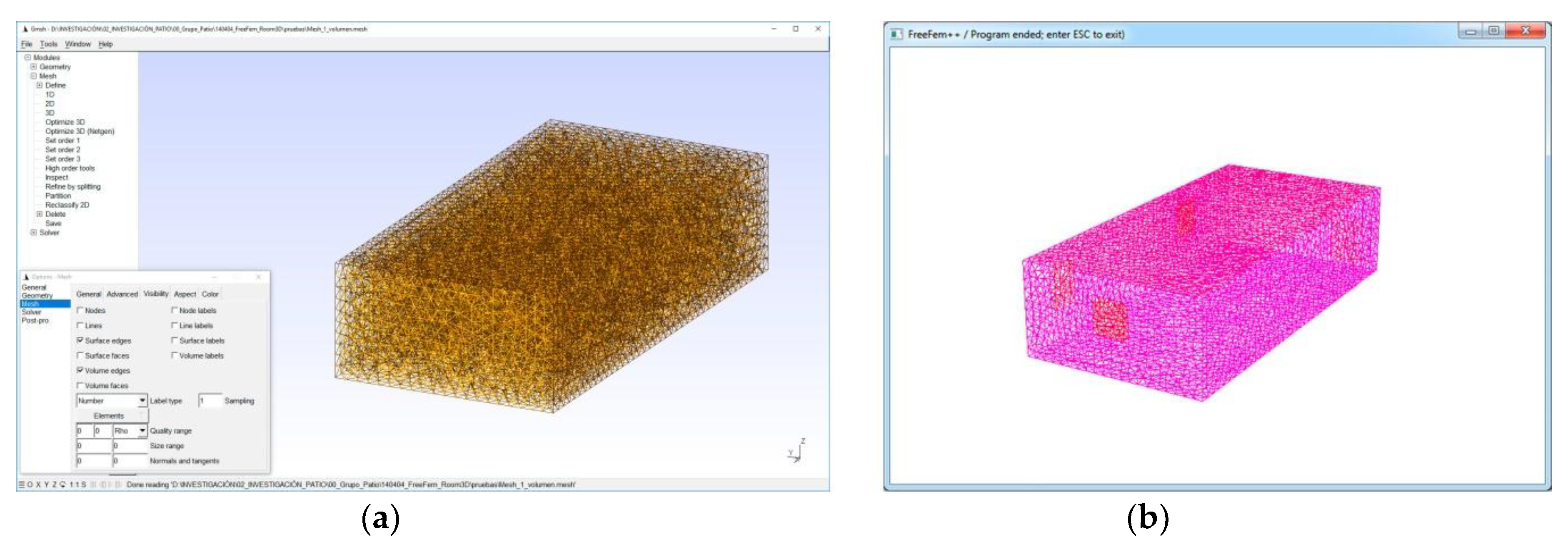
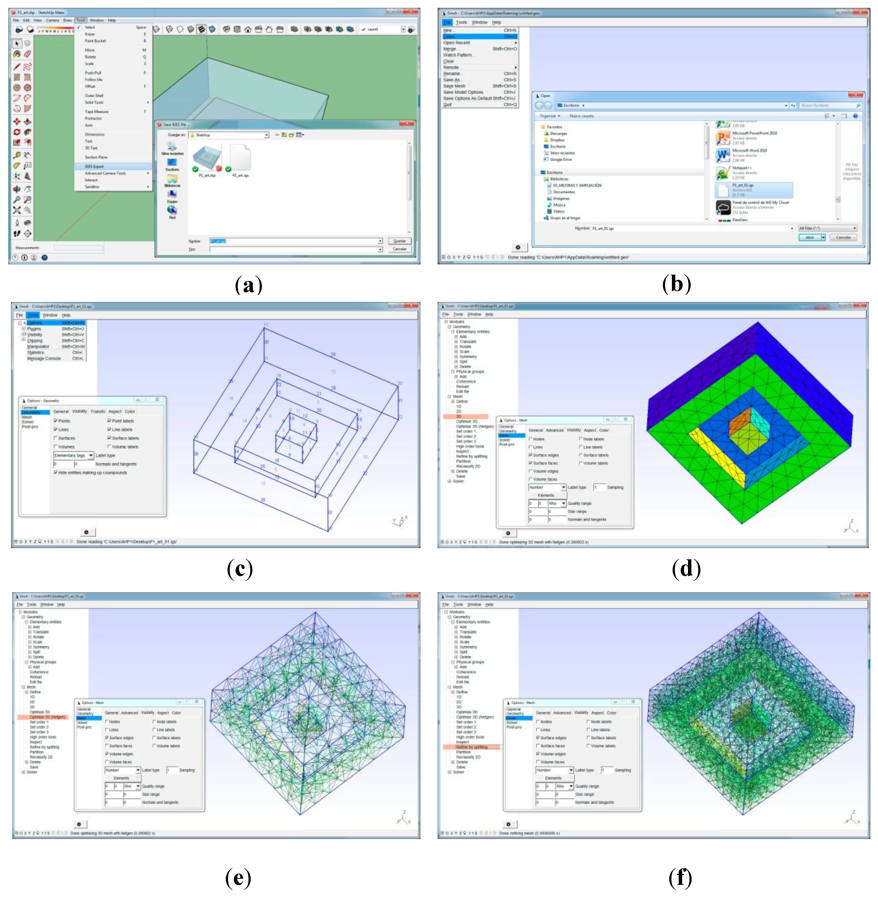
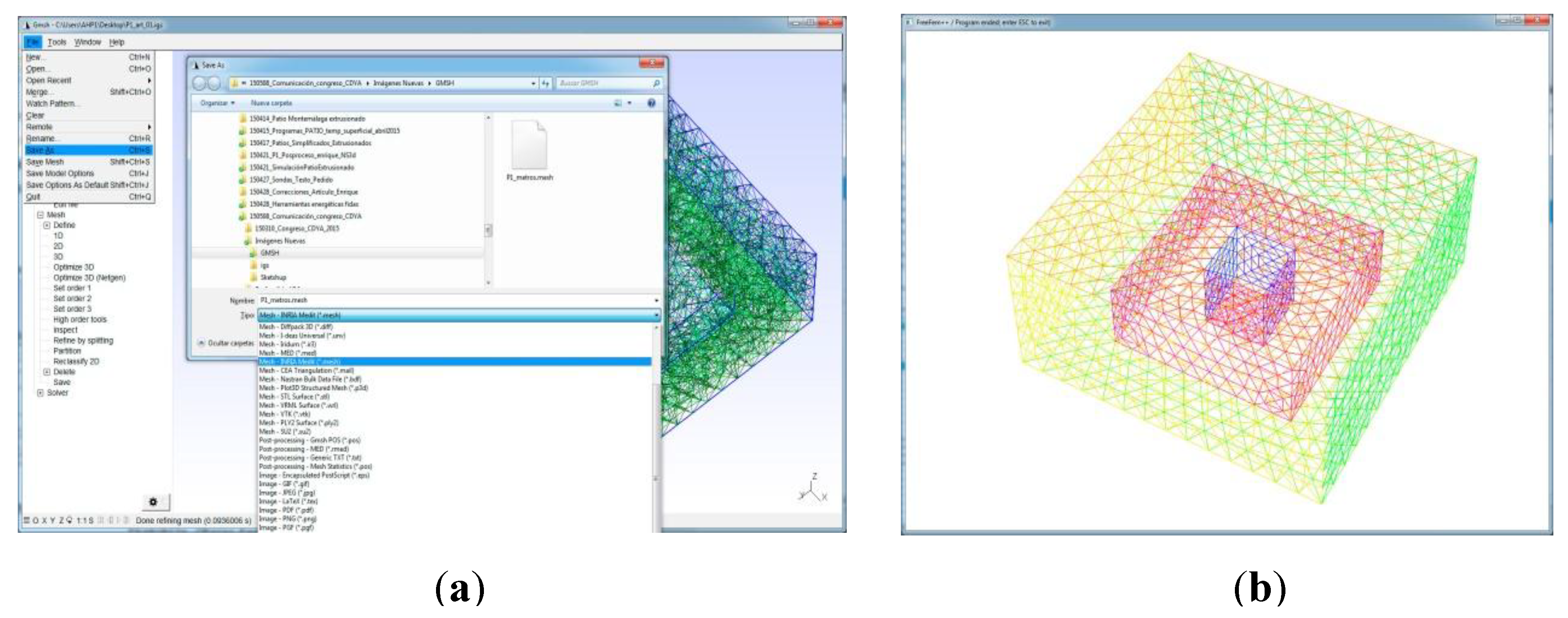
3.2. GMESH Analysis
4. Computer-Aided Design Programs
4.1. AutoCAD
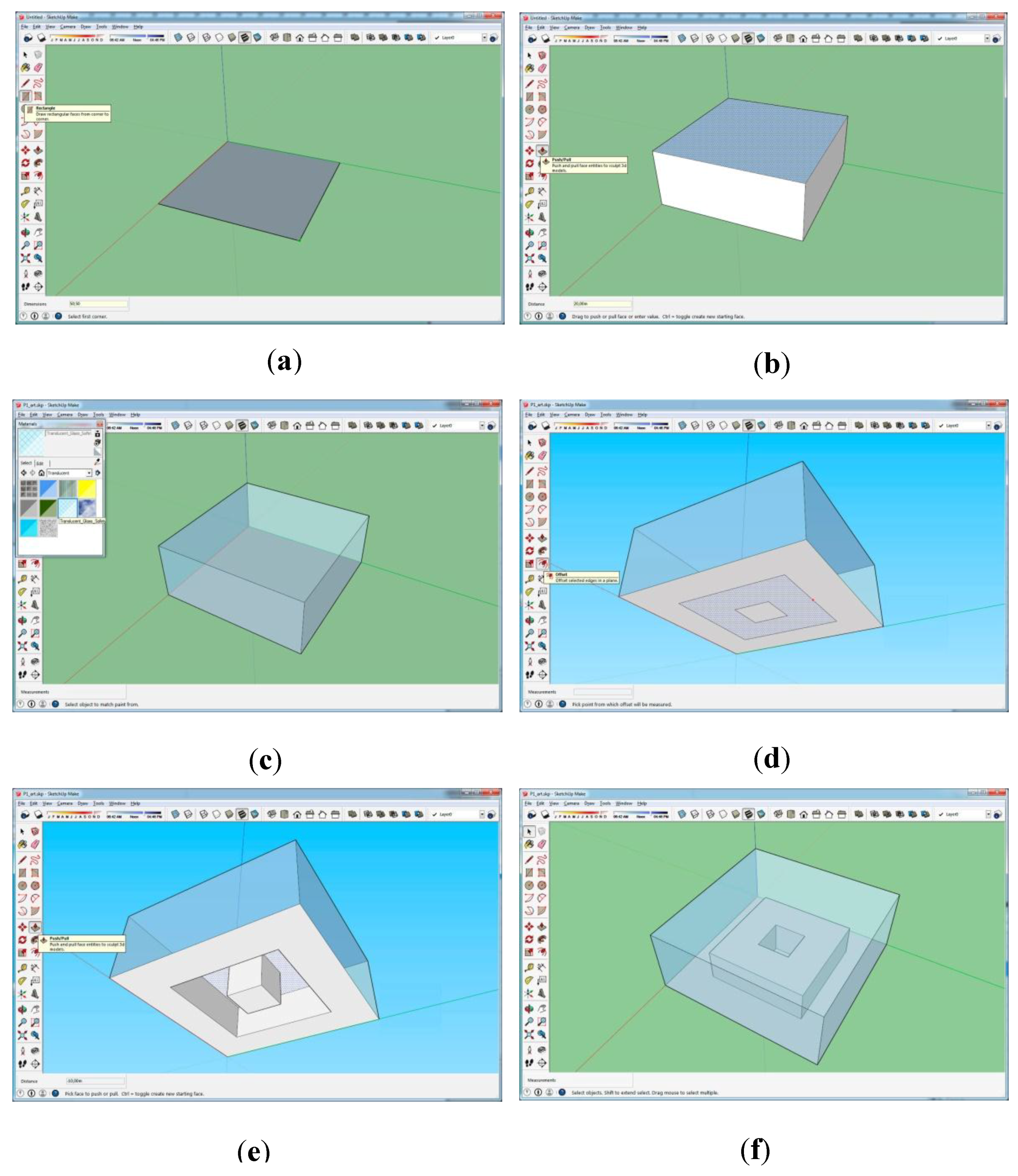
4.2. SketchUp
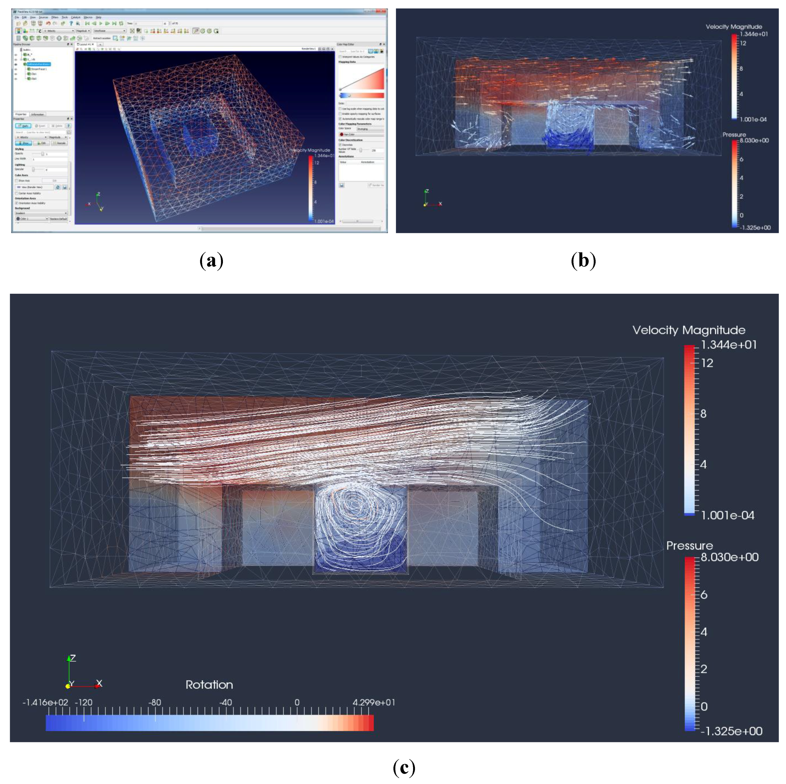
4.3. ParaView
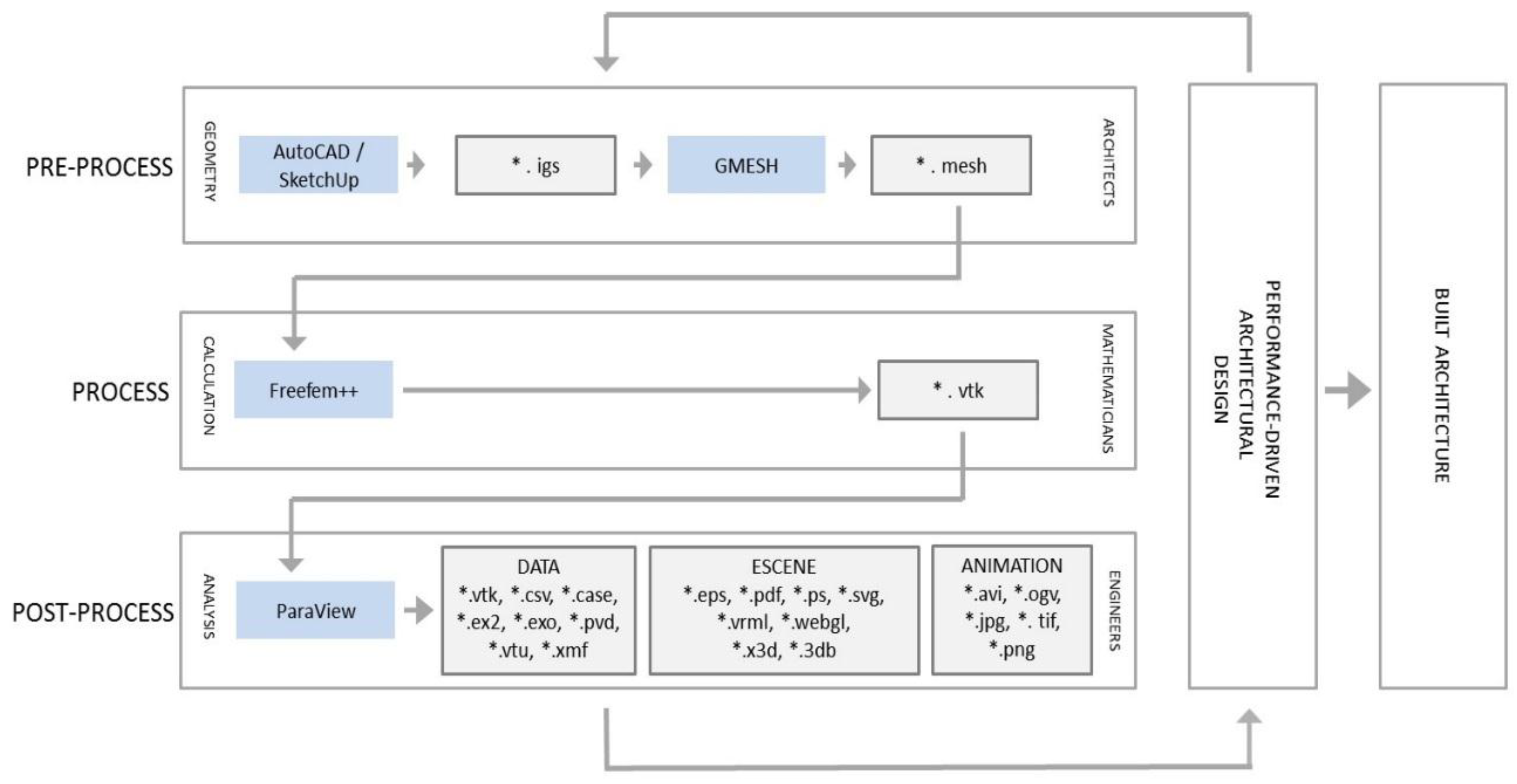
5. Proposed Plug-In Procedure
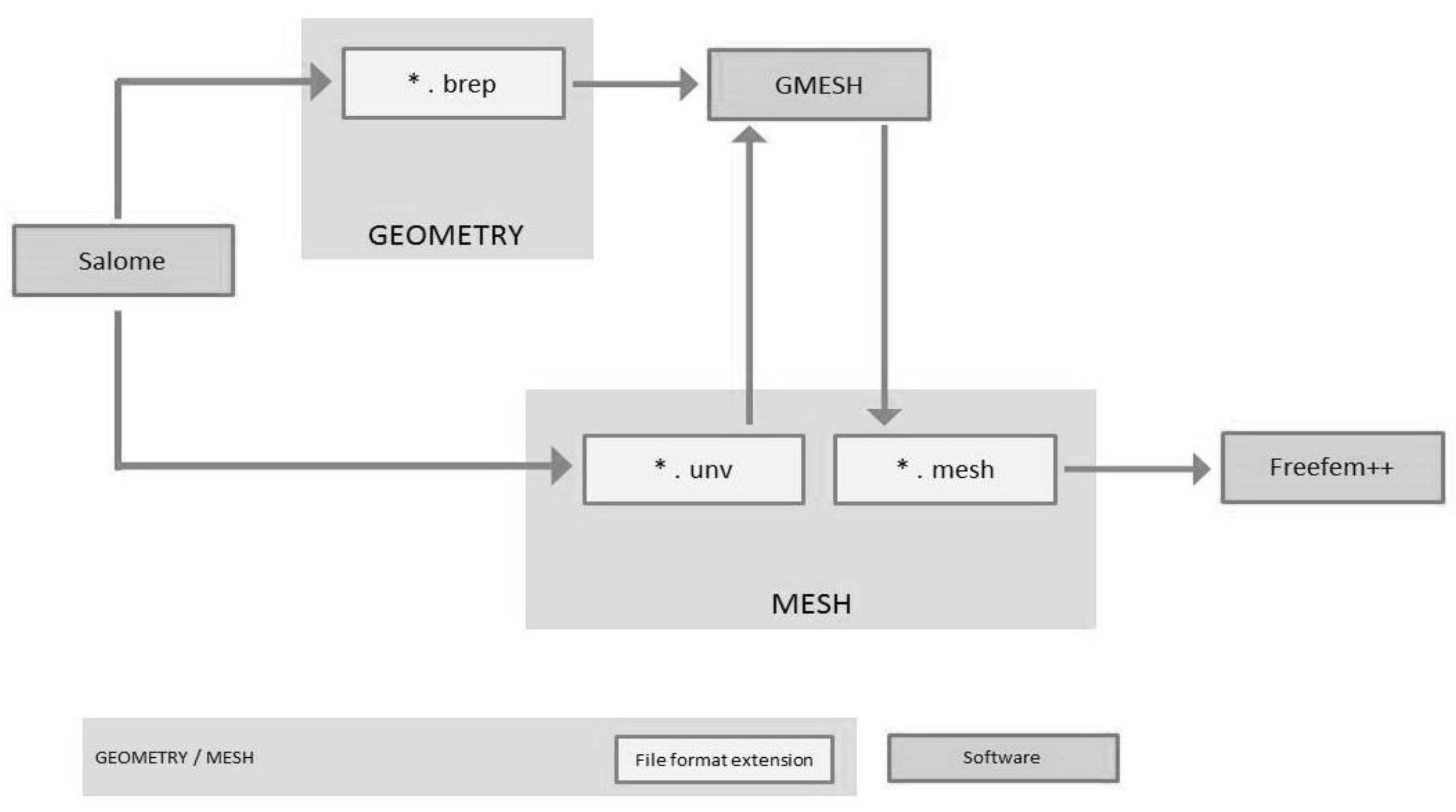
5.1. File Exchange
5.2. Case Study
| load "msh3" |
| load "medit" |
| load "tetgen" |
| load "mshmet" |
| load "UMFPACK64" |
| load "iovtk" |
| real nu=0.000015; |
| real dt=0.1; |
| real tfinal=3600; |
| real dts=60; |
| real t=0; |
| real tsave=dts; |
| mesh3 Th=readmesh3("P_1.mesh"); |
| fespace Vh(Th,P1b3d); |
| fespace Ph(Th,P13d); |
| Vh uu1,uu2,uu3,v1,v2,v3; |
| Vh u1=0,u2=0,u3=0; |
| Ph p,q; |
| problem NavierStokes3d(uu1,uu2,uu3,p,v1,v2,v3,q,solver=sparsesolver) = |
| int3d(Th)((uu1*v1+uu2*v2+uu3*v3)/dt |
| +nu*(dx(uu1)*dx(v1)+dy(uu1)*dy(v1)+dz(uu1)*dz(v1)) |
| +nu*(dx(uu2)*dx(v2)+dy(uu2)*dy(v2)+dz(uu2)*dz(v2)) |
| +nu*(dx(uu3)*dx(v3)+dy(uu2)*dy(v3)+dz(uu3)*dz(v3)) |
| −(dx(uu1)+dy(uu2)+dz(uu3))*q |
| −(dx(v1)+dy(v2)+dz(v3))*p + 1e-10*q*p) |
| +int3d(Th)(−convect([u1,u2,u3],-dt,u1)*v1/dt |
| −convect([u1,u2,u3],-dt,u2)*v2/dt |
| −convect([u1,u2,u3],-dt,u3)*v3/dt) |
| +on(4,uu1=(10.0)*(z>9.0),uu2=0,uu3=0) |
| +on(1,7,8,10,11,9,12,13,14,15,16,uu1=0,uu2=0,uu3=0); |
| int i=0; |
| while (t<= tfinal){ |
| NavierStokes3d; |
| u1=uu1; |
| u2=uu2; |
| u3=uu3; |
| t += dt; |
| cout << "Time: " << t << " tsave: " << tsave << endl; |
| if (abs(t-tsave)< 0.0001) |
| { |
| i++; |
| savevtk("it_"+i+".vtk",Th,[u1,u2,u3],p,dataname="Velocity Pressure"); |
| tsave+=dts; |
5.3. Results
6. Conclusions
Supplementary Materials
Author Contributions
Funding
Acknowledgments
Conflicts of Interest
References
- Fernandez-Nieto, E.D.; Lucas, C.; de Luna, T.M.; Cordier, S. On the influence of the thickness of the sediment moving layer in the definition of the bedload transport formula in Exner systems. Comput. Fluids 2014, 91, 87–106. [Google Scholar] [CrossRef]
- De La Flor, F.S.; Domınguez, S.A. Modelling microclimate in urban environments and assessing its influence on the performance of surrounding buildings. Energy Build. 2004, 36, 403–413. [Google Scholar] [CrossRef]
- Alvarez, S. Experimental work and analysis of confined urban spaces. Sol. Energy 2001, 70, 263–273. [Google Scholar]
- Rojas, J.M.; Galán-Marín, C.; Fernández-Nieto, E.D. Parametric study of thermodynamics in the mediterranean courtyard as a tool for the design of eco-efficient buildings. Energies 2012, 5, 2381–2403. [Google Scholar] [CrossRef]
- Shi, X.; Yang, W. Performance-driven architectural design and optimization technique from a perspective of architects. Autom. Constr. 2013, 32, 125–135. [Google Scholar]
- Yi, Y.K.; Malkawi, A.M. Optimizing building form for energy performance based on hierarchical geometry relation. Autom. Constr. 2009, 18, 825–833. [Google Scholar] [CrossRef]
- Rojas-Fernández, J.M.; Domínguez-Hernández, L. Corporate Web of Arquitectos Hombre de Piedra. Available online: https://hombredepiedra.com/en/research/mediterranean-courtyard/ (accessed on 2 July 2018).
- Abanda, F.H.; Vidalakis, C.; Oti, A.H.; Tah, J.H. A critical analysis of Building Information Modelling systems used in construction projects. Adv. Eng. Softw. 2015, 90, 183–201. [Google Scholar] [CrossRef]
- Mansuri, D.; Chakraborty, D.; Elzarka, H.; Deshpande, A.; Gronseth, T. Building Information Modeling enabled Cascading Formwork Management Tool. Autom. Constr. 2017, 83, 259–272. [Google Scholar] [CrossRef]
- Pärn, E.A.; Edwards, D.J. Conceptualising the FinDD API plug-in: A study of BIM-FM integration. Autom. Constr. 2017, 80, 11–21. [Google Scholar] [CrossRef]
- NBS. Building Information Modelling Report. 2016. Available online: http://www.thenbs.com/pdfs/NBS-National-BIM-Report-2016.pdf (accessed on 2 July 2018).
- López-Cabeza, V.P.; Galán-Marín, C.; Rivera-Gómez, C.; Roa-Fernández, J. Courtyard microclimate ENVI-met outputs deviation from the experimental data. Build. Environ. 2018, 144, 129–141. [Google Scholar] [CrossRef]
- Ramírez-Balas, C.; Fernández-Nieto, E.; Narbona-Reina, G.; Sendra, J.; Suárez, R. Thermal 3D CFD Simulation with Active Transparent Façade in Buildings. Energies 2018, 11, 2265. [Google Scholar] [CrossRef]
- Official Web of ANSYS Fluent. Available online: https://www.ansys.com/es-es/products/fluids/ansys-fluent (accessed on 2 July 2018).
- Official Web of DesignBuilder. Available online: http://www.designbuilder.co.uk/ (accessed on 2 July 2018).
- Official Web of Autodesk Ecotec Analysis. Available online: http://usa.autodesk.com/ecotect-analysis/ (accessed on 2 July 2018).
- Chronis, A.; Liapi, K.A.; Sibetheros, I. A parametric approach to the bioclimatic design of large scale projects: The case of a student housing complex. Autom. Constr. 2012, 22, 24–35. [Google Scholar] [CrossRef]
- Robinson, D.; Campbell, N.; Gaiser, W.; Kabel, K.; Le-Mouel, A.; Morel, N.; Stone, A. SUNtool-A new modelling paradigm for simulating and optimising urban sustainability. Sol. Energy 2007, 81, 1196–1211. [Google Scholar] [CrossRef]
- Idczak, M.; Groleau, D.; Mestayer, P.; Rosant, J.M.; Sini, J.F. An application of the thermo-radiative model SOLENE for the evaluation of street canyon energy balance. Build. Environ. 2010, 45, 1262–1275. [Google Scholar] [CrossRef]
- Matzarakis, A.; Rutz, F.; Mayer, H. Modelling radiation fluxes in simple and complex environments: Basics of the RayMan model. Int. J. Biometeorol. 2010, 54, 131–139. [Google Scholar] [CrossRef] [PubMed]
- Tumini, I.; Higueras-García, E. Strengths and weaknesses of urban microclimate simulation tools. DYNA Energía Sostenibilidad 2013, 1, 1–17. [Google Scholar]
- Official Web of EnergyPlus. Available online: http://apps1.eere.energy.gov/buildings/energyplus/ (accessed on 2nd July 2018).
- Official Web of ENVI-Met. Available online: http://www.envi-met.com/ (accessed on 2 July 2018).
- Yang, X.; Zhao, L.; Bruse, M.; Meng, Q. Evaluation of a microclimate model for predicting the thermal behavior of different ground surfaces. Build. Environ. 2013, 60, 93–104. [Google Scholar] [CrossRef]
- Yang, X.; Zhao, L.; Bruse, M.; Meng, Q. An integrated simulation method for building energy performance assessment in urban environments. Energy Build. 2012, 54, 243–251. [Google Scholar] [CrossRef]
- Official Web of Freefem++. Available online: http://www.freefem.org/ (accessed on 2 July 2018).
- Fernández, F.J.; Alvarez-Vázquez, L.J.; Martínez, A.; Vázquez-Méndez, M.E. A 3D optimal control problem related to the urban heat islands. J. Math. Anal. Appl. 2017, 446, 1571–1605. [Google Scholar] [CrossRef]
- Ramírez-Balas, C.; Fernández-Nieto, E.D.; Narbona-Reina, G.; Sendra, J.J.; Suárez, R. Numerical simulation of the temperature evolution in a room with a mur neutralisant. Application to “The City of Refuge” by Le Corbusiero. Energy Build. 2015, 86, 708–722. [Google Scholar] [CrossRef]
- Bernard Barrois, Example of Use of Freefem ++ for an Object 3D. Web on Freefem ++ Inside the Official Web of the Univerisad of Murcia. Available online: http://www.um.es/freefem/ff++/pmwiki.php?n=Main.Room3D (accessed on 2 July 2018).
- Zhang, R.; Zhang, Y.; Lam, K.P.; Archer, D.H. A prototype mesh generation tool for CFD simulations in architecture domain. Build. Environ 2010, 45, 2253–2262. [Google Scholar] [CrossRef]
- Official Web of Salome Software. Available online: http://www.salome-platform.org/ (accessed on 2 July 2018).
- Official Web of GMESH. Available online: http://geuz.org/gmsh/ (accessed on 2 July 2018).
- Almhafdy, A.; Ibrahim, N.; Ahmad, S.S.; Yahya, J. Courtyard Design Variants and Microclimate Performance. Procedia-Soc. Behav. Sci. 2013, 101, 170–180. [Google Scholar] [CrossRef]
- Official Web of Sketchup. Available online: http://www.sketchup.com/ (accessed on 2 July 2018).
- Exports the Model to IGES Format. Available online: http://rhin.crai.archi.fr/rld/download.php?file=iges_export_V0.6.zip (accessed on 2 July 2018).
- Official Web of ParaView. Available online: http://www.paraview.org/ (accessed on 2 July 2018).
- Save in vtk File from Freefem++ and Read from ParaView. Inside the Official Web of Universidad de Murcia. Available online: http://www.um.es/freefem/ff++/uploads/Main/paraview_freefem_english.pdf (accessed on 2 July 2018).
- Geyer, P.; Stopper, J.; Lang, W.; Thumfart, M. A Systems Engineering Methodology for Designing and Planning the Built Environment—Results from the Urban Research Laboratory Nuremberg and Their Integration in Education. Systems 2014, 2, 137–158. [Google Scholar] [CrossRef]


 fulfilled issue
  pending issue
| Software Analysed | Outdoor Conditions Simulations | Simulations Using CFD | Free Software | Open Sauce | AutoCAD/Sketchup Import |
|---|---|---|---|---|---|
| ANSYS Fluent | | | | ||
| DesignBuilder | | | | ||
| Revit/Ecotect Analysis | | | |||
| SUNtool | | | |||
| Solene | | | |||
| RayMan | | | |||
| URSUS | | | |||
| GreenCanyon | | | | ||
| EnergyPlus | | | | | |
| ENVI-met | | | | ||
| Software using FreeFem++ | | | | | |
© 2018 by the authors. Licensee MDPI, Basel, Switzerland. This article is an open access article distributed under the terms and conditions of the Creative Commons Attribution (CC BY) license (http://creativecommons.org/licenses/by/4.0/).
Share and Cite
Rojas-Fernández, J.; Galán-Marín, C.; Rivera-Gómez, C.; Fernández-Nieto, E.D. Exploring the Interplay between CAD and FreeFem++ as an Energy Decision-Making Tool for Architectural Design. Energies 2018, 11, 2665. https://doi.org/10.3390/en11102665
Rojas-Fernández J, Galán-Marín C, Rivera-Gómez C, Fernández-Nieto ED. Exploring the Interplay between CAD and FreeFem++ as an Energy Decision-Making Tool for Architectural Design. Energies. 2018; 11(10):2665. https://doi.org/10.3390/en11102665
Chicago/Turabian StyleRojas-Fernández, Juan, Carmen Galán-Marín, Carlos Rivera-Gómez, and Enrique D. Fernández-Nieto. 2018. "Exploring the Interplay between CAD and FreeFem++ as an Energy Decision-Making Tool for Architectural Design" Energies 11, no. 10: 2665. https://doi.org/10.3390/en11102665
APA StyleRojas-Fernández, J., Galán-Marín, C., Rivera-Gómez, C., & Fernández-Nieto, E. D. (2018). Exploring the Interplay between CAD and FreeFem++ as an Energy Decision-Making Tool for Architectural Design. Energies, 11(10), 2665. https://doi.org/10.3390/en11102665