1. Introduction
Real-time (RT) simulation means that the time that is required by the simulation platform to complete the computation of state outputs for each step size is shorter than or equal to the selected step size [
1], which can be used for design, prototype construction, hardware-in-the-loop testing, teaching, and training [
2]. Electromagnetic transient (EMT) simulation generally calculates with a 30–100 μs time-step [
3], which is mainly used for closed-loop testing of control systems, such as static var compensators (SVCs), synchronous condensers, and protection devices [
4]. Although it is considered to be more precise, its simulation calculation burden is heavy, which limits the simulation scale [
5]. The typical calculation time-step of transient stability analysis (TSA) simulation is 8–10 ms [
2]. Although it sacrifices the description of fast transients, harmonics, and electromagnetic nonlinearities, it can be used for closed-loop testing of power flow controllers and energy storage equipment, and dispatcher training, etc. TSA has the advantage of large system analysis [
2,
4,
5,
6], therefore, it is not always necessary to perform EMT simulation on the whole system, only the part that needs detailed study. When the computational resources of the large-scale power system for EMT simulation are insufficient, a feasible solution is that the part requiring detailed study performs EMT simulation and the rest perform TSA simulation. Both are connected through an interface.
Interface technology is the key to hybrid simulation [
7]. The interface technology of hybrid simulation mainly involves three aspects: equivalent method, interaction timing, and interface position selection. Regarding the equivalent method, when simulating the TSA sub-system, the EMT sub-system is generally replaced by a power source [
7,
8,
9], a current source [
10,
11,
12], or a Thevenin (Norton) equivalent [
13]. The power source equivalent is the most common EMT sub-system equivalent in the current EMT–TSA hybrid simulation. The current source equivalent is the most direct among the three equivalent methods. Its basic idea is to measure the phasor of the fundamental wave current of each sequence and directly transmit it to the TSA side [
14]. When simulating the EMT sub-system, the TSA sub-system is generally replaced by the Thevenin (Norton) equivalent, which is based on fundamental frequency [
14]. Regarding interaction timing, in view of the shortcomings that the interface error of current parallel data interaction mode is large, an improved parallel data interaction scheme is presented [
15]. The core of the data interaction scheme is to use the EMT sub-system historical calculation results to predict the parameters that are required in the current iterative calculation of the TSA subprogram. To reduce the influence of communication delay on simulation accuracy, an interface electrical quantity interaction method, which is based on the principle of using the other party’s simulation data as early as possible, is proposed [
16]. When considering interface location selection, there are currently two ideas for developing network partition schemes: To reduce the modeling amount of the electromagnetic sub-system, the interface position is often set at the DC converter bus [
17,
18]. According to the need to partition the network at a low asymmetry position, the interface position is extended to the TSA side [
10,
19]. However, existing network partition schemes cannot be used for pure AC power networks. Concerning accuracy, hybrid simulation is more suitable for an AC system [
20,
21,
22], so the network partition scheme for an AC system is very important. Some work has pointed out that, for the actual large-scale interconnected power grid, the network partitioning scheme should analyze the coupling relationship between the various parts of the system analytically and carry out the network partition scheme in the position where the system coupling relationship is most clear [
23], however, no specific practice is suggested.
Following the target power system being carried out to network partitioning in the existing works, the areas of EMT simulation and TSA simulation are often fixed. To make the area of EMT simulation flexible to change, the current authors propose the method of hybrid real-time simulation of the variable area of interest in this paper. That is, according to the difference of interest areas, EMT simulation of different areas is performed in different periods, and TSA simulation is performed on other areas. The authors divide the simulation object into multiple sub-networks. The EMT simulation range of an area of interest is determined according to the voltage drop depth at the boundary of the adjacent sub-network that is caused by the three-phase short-circuit fault at the boundary of each area of interest. According to the characteristics of a hybrid real-time simulation of variable area of interest, the Norton equivalent is obtained by using the sub-network as a basic unit. The calculations on the electromagnetic side and the TSA side mainly include three steps. Based on this, a general model of the contact system is constructed. The contact system consists of the Norton equivalents of electromagnetic sub-networks and the Norton equivalents of the TSA models of the remaining sub-networks. The electromagnetic sub-network forms its own Norton equivalent model on the TSA side by means of the positive sequence components of voltage and current that are extracted by the discrete sequence at its interfaces and the Norton equivalent admittance of its TSA model. Looking at the problem of large interface error in the parallel data interaction mode, which is caused by the use of the previous time-step equivalent parameters on both the TSA side and the electromagnetic side [
15], the fundamental phasor prediction and the Norton equivalent current source prediction are used to reduce the interface error.
The rest of the paper is organized as follows. The simulation object is divided into multiple sub-networks and a network partition scheme is provided in
Section 2.
Section 3 presents the overall framework of hybrid real-time simulation of the variable area of interest.
Section 4 details the relevant practices of the TSA side.
Section 5 presents the specific practices of the EMT side.
Section 6 presents the case studies and the simulation results. Finally, brief conclusions are made in
Section 7.
2. Network Partition Scheme
To facilitate the switching between an electromagnetic transient (EMT) program and the corresponding transient stability analysis (TSA) program and to determine the EMT simulation range, the authors first divide the large power network into multiple sub-networks. Based on this, the EMT simulation range corresponding to each sub-network is determined. The simulation range does not change with different faults or operations in the sub-network.
2.1. Determination of the Sub-Networks
To avoid excessive writing of EMT programs and to avoid the situation that obtaining an equivalent model and calculating the contact system, which will cause an excessive additional amount of calculation (relative to the case of no network segmentation) in the case of an excessive number of interfaces, the sub-network that is generated by division cannot be too small. Since the target system is large, the interface position is only set at the boundary. When a fault or operation occurs at the boundary, the surrounding sub-networks are included in the scope of EMT simulation. When the sub-network that is generated by division is too large, it is not conducive to the improvement of simulation efficiency. Therefore, the sub-network that is generated by division should not be too small or too large. Under the above principle, the simulation object is divided into multiple sub-networks, each of which is an area of interest.
2.2. Determination of EMT Simulation Range
The lighter the voltage drops, the lower the harmonic content, and TSA simulation only considers the fundamental frequency component. Therefore, when the fault occurs, the voltage drop depth can be used to determine the affiliated area corresponding to each sub-network. The affiliated area is an area that extends outward to ensure the accuracy of the simulation of the area of interest. The sub-network and its affiliated area are the EMT simulation range corresponding to each sub-network. The voltage drop depth is defined as:
where
and
are the voltage amplitudes before and after the fault, respectively.
Since the three-phase short-circuit fault has the widest influence range under the same conditions, a three-phase short-circuit fault can be set at the boundary of each sub-network, and the voltage drop depth at the fault location is used as a reference. When the ratio of to of nodes at adjacent boundaries is less than (threshold), then the impact of faults on these nodes is negligible. These nodes at the boundary can be used as interface nodes. When the ratio is larger than , the remaining boundary nodes that are closer to the fault location should be detected again until all of the nodes that meet the requirements are found. This will determine the range of EMT simulation.
3. Overall Framework of Hybrid Real-Time Simulation of Variable Area of Interest
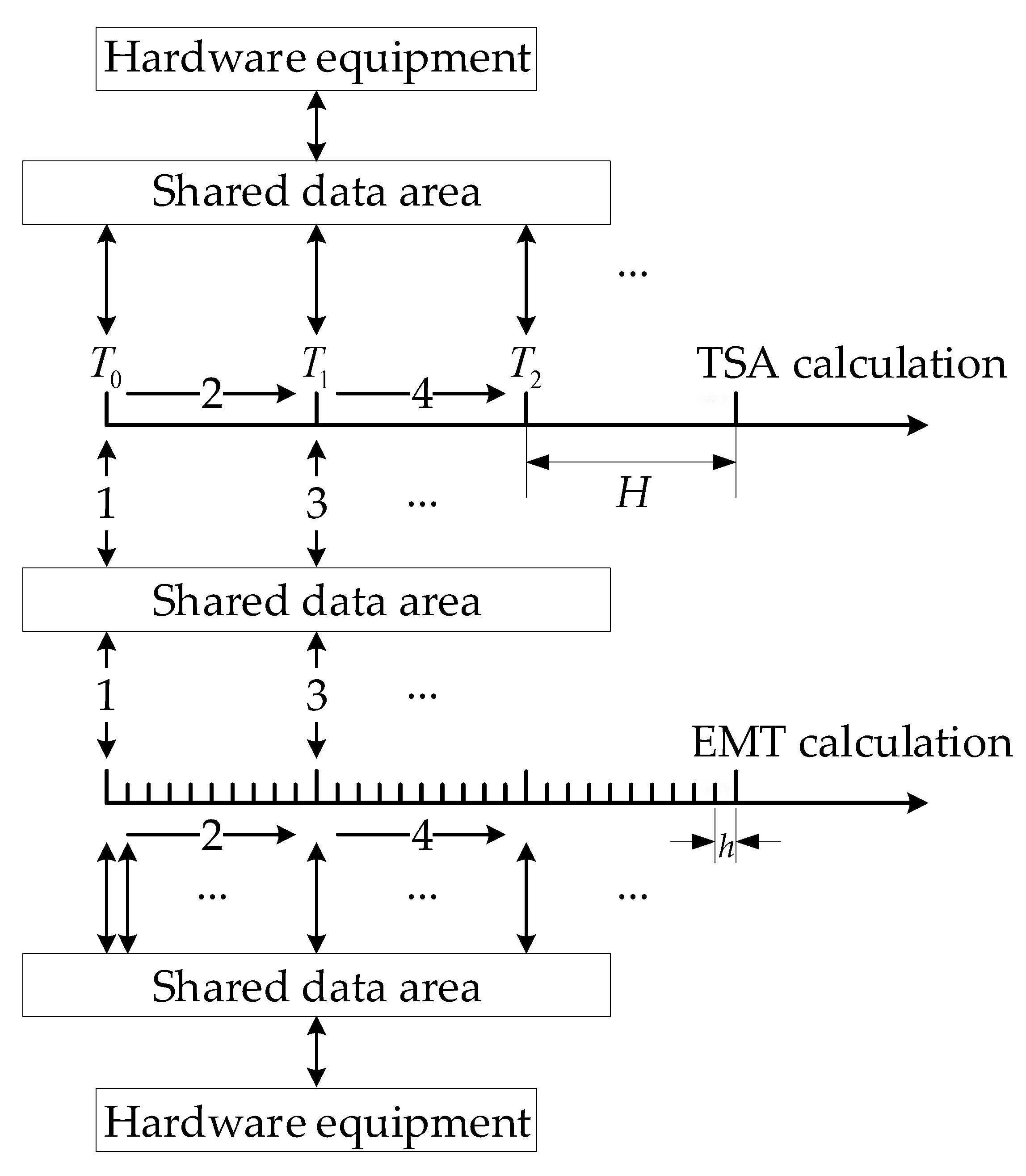
Real-time simulation needs to meet the requirements of hardware closed loop and real-time, therefore, the overall protocol for system interaction is shown in
Figure 1. Regarding hardware-in-the-loop, the relevant output information of the electromagnetic side is written into the shared data area in a small time-step, the relevant output information on the TSA side is written into the shared data area in a large time-step and the output information that is processed by the input/output program is transmitted to the hardware equipment. The input/output program is a program that processes input and output data. The information input by the hardware device is written to the shared data area after being processed by the input/output program. The EMT and TSA calculation processes can read the required information from the shared data area. TSA simulation is performed with a large time-step size
H and EMT with a small time-step size
h. The two are performed in parallel. The shared data area contains multiple storage units.
To make the areas of EMT and TSA simulation flexible to change, the external equivalent model is obtained from the sub-network.
While considering the characteristics of a hybrid real-time simulation of a variable area of interest, the model of the contact system needs to be kept unchanged, therefore, it is necessary to construct a general model for the calculation of the contact system. To this purpose, the calculations on the electromagnetic and TSA sides mainly include three steps: obtaining the equivalence models needed to build the contact system, the calculation of the contact system, and the calculation of each sub-network itself.
TSA simulation is performed on all sub-networks, and parallel calculation is performed between sub-networks. The sub-networks within the scope of the EMT sub-system perform both EMT and TSA simulation.
The information interaction diagram of the whole system is shown in
Figure 2.
represents the
k-th sub-network in
Figure 2. The area where
is located is the model area. The TSA model of all sub-networks completes obtaining the equivalent parameters of the TSA sub-networks, the attaining of the equivalent parameters II of electromagnetic sub-networks, and the calculation of the TSA sub-networks themselves. The EMT model of the sub-networks completes the acquiring of the equivalent parameters I of electromagnetic sub-networks and the calculation of the electromagnetic sub-networks themselves. Both
and
represent the equivalent parameters of the
k-th sub-network, but they represent different meanings.
represents the voltage and current values at the
k-th sub-network interface (the interface parameters). The interface parameters are calculated by the contact system. The interface parameters on the TSA side are used for the calculation of the TSA sub-networks themselves. The electromagnetic side interface parameters are used not only for the calculation of the electromagnetic sub-networks themselves, but also for the phasor extraction of the TSA side. The area where
,
, and
are located is the data area. To use the parameters conveniently, the relevant parameters on both sides are stored in different storage units by sub-network number. The components in the ellipse belong to the electromagnetic side. The sub-network within the solid ellipse is the area of interest, and the sub-network within the dashed ellipse is the affiliated area. The area of interest contains only one sub-network, while the affiliated area might contain multiple sub-networks. The components in the rectangle belong to the TSA side. Arrows indicate the process of information interaction. To describe more easily, the “equivalent parameters of TSA sub-networks” appears twice in
Figure 2, but their parameters and storage addresses are identical. The contact system exists in the form of phasors in the process of TSA calculation. It is recorded as the TSA model of the contact system. The contact system exists in the form of instantaneous value in the EMT calculation process. It is recorded as the EMT model of the contact system. The role of the pre-processing of the TSA sub-network equivalent parameters is to predict the equivalent current sources (or equivalent voltage sources) of the next time-step of the TSA sub-networks and to realize the discretization of the equivalent current sources (or equivalent voltage sources) according to the electromagnetic step size.
Only one of the equivalent parameters that were obtained from the same sub-network under different modeling methods is used by the corresponding contact system. The sub-networks … that perform EMT simulation are variable. The EMT model of the sub-networks vary with the difference of the areas that perform EMT simulation. The TSA model of all sub-networks, the TSA model of the contact system, and the EMT model of the contact system are invariant. Their storage space is also invariant and only the parameters of them are changed. The interface parameters of the EMT side and the equivalent parameters of the TSA sub-networks are stored in a plurality of storage units for ping-pong operations between the EMT side and TSA side, respectively. The ping-pong frequencies on both sides are H, and the data of two or more time-steps of the same parameter can be saved. To write programs conveniently, the voltages and the currents at all sub-network interfaces on the electromagnetic side are carried out via phasor extraction.
4. The Simulation of TSA Side
To ensure the consistency of the external characteristics of the TSA and EMT models of the same component in steady state, and to obtain the equivalent model of the TSA sub-network easily, the component models should be simplified and preprocessed. The load adopts the constant impedance model. The line adopts the pi-type, quasi-steady-state model. The transformer is the ideal transformer and it adopts the pi-type equivalent model [
24]. The generator uses a six-order detailed model and it is processed as a virtual injection current in parallel with a virtual admittance.
4.1. The Construction Method of TSA General Model of Contact System
The TSA model and the EMT model of the same sub-network have the same external equivalent form, so the models of the contact system are unchanged. Second, when the EMT and TSA sub-systems are equivalent to the first-order boundary condition (the Thevenin or Norton equivalent), the iterative factor is the smallest under the same conditions, which is beneficial to accelerate the convergence of the system iteration [
25], since fast convergence is critical for real-time simulation applications. Therefore, both the TSA sub-network and the EMT sub-network are replaced by a Norton equivalent.
The Norton equivalents of the TSA model of all sub-networks are obtained according to the method [
13]. The Norton equivalent of an EMT sub-network is derived from the modified Norton equivalent of the TSA model of the sub-network. Since the corresponding TSA sub-network is applied with the same fault or operation at the same time when the EMT sub-network fails or operates, the Norton admittance
of the corresponding TSA model does not require correction. Only the Norton equivalent current source of its TSA model needs to be corrected. The correction method is as follows.
According to the discrete sequence that was calculated by the EMT model of the contact system, the voltage positive sequence component
at the interface and the current positive sequence component
of each branch are obtained by fitting. According to
,
, and the equivalent admittance
at the interface, the modified Norton current source
is given by:
4.2. Phasor Extraction
To reduce the computational burden on the electromagnetic side, the phasor extraction is performed on the TSA side. The phasor is extracted by the method [
26,
27] in this paper. The phasors are extracted from the voltage and current waveforms at the boundary buses, which are provided by EMT simulation. To be clear, the presentation deals with currents, but the processing of the voltages is similar.
The amplitude and the phase angle of the current positive sequence component are computed from the three time-varying current waveforms by projecting the latter on (
x,
y) reference axes. These are the axes used in the TSA simulation to project the rotating vectors that are associated with quasi-sinusoidal variables and obtain their corresponding rectangular components. This is shown in
Figure 3, where
and
are the components of phasor
, all three varying with time.
The reference axes are taken as rotating at the angular velocity
in the TSA simulation. Thus, at time
t, the angle between the
x-axis and a fixed reference is (see
Figure 3):
assuming that the
x-axis and the reference axis coincide at
t = 0.
The vector of projected currents,
, is obtained from the three-phase instantaneous currents,
, using the linear transformation:
where:
When the three-phase currents were balanced at the fundamental frequency, for example:
then, it is easy to conclude that:
which shows that the components of
are indeed the projections on
x and
y of a vector rotating at angular velocity
, having amplitude
, and a phase angle
relative to the
x-axis, as shown in
Figure 3.
and
are the real and imaginary parts of the current phasor required in the TSA simulation, respectively.
This phasor extraction technique does not introduce a delay that is associated with the processing of the waveforms at times prior to
t +
H [
27].
Equation (7), however, is applicable only to balanced three-phase currents at a fundamental frequency. When the effects of a fault that is located in the EMT sub-system are felt at the boundary between the EMT and TSA sub-systems, the boundary current waveforms are affected by “noise”, consisting of aperiodic, negative and zero-sequence components, and harmonics. Therefore, filtering is necessary to eliminate their effects.
The aperiodic (regarding the negative-sequence) components present in
will show their effects on
in the form of fundamental (regarding double-fundamental) frequency sinusoidal components. The Butterworth low pass filter [
28] can be used for filtering.
4.3. Fundamental Phasors Prediction
Since the fundamental-frequency voltage and current phasors are extracted according to the interface information of the EMT side of the last TSA step size, if the phasors are directly used in the calculation of the Norton equivalent current sources, it will cause a large interface error. Interface errors can be reduced by predicting the fundamental voltage and current phasors. The presentation deals with the fundamental current phasors, but the fundamental voltage phasors are treated similarly. The details are as follows.
The amplitude
and the phase angle
of fundamental current phasors that are required for the calculation of the current step size are predicted based on the fundamental current phasors extracted by the current and the last time-steps of the TSA side. Concerning the first-order (linear) prediction, their values are given by the following equation:
6. Case Studies and Simulation Results
The IEEE 118-bus system is taken as an example, and the example system is shown in
Figure 4. A field programmable gate array (FPGA) is used as the simulation platform for testing. An EMT simulation is performed with 50 μs, and TSA simulation with 10 ms. The implicit trapezoidal method is used for differentiating.
6.1. The Network Partition Result
Twenty-seven areas of interest are set in the IEEE 118-bus system; thus, 27 sub-networks are generated. To simplify, only partial network partitioning results are given. The nodes that are included in each sub-network are shown in
Table 1. The same nodes in every two sub-networks are boundary nodes.
Subsequent to repeated experiments, to meet the simulation accuracy requirements, can be taken to 0.03–0.034, and, on this basis, the affiliated area corresponding to each sub-network can be determined. To simplify, only the affiliated areas of sub-networks 6, 7, and 20 are given. The affiliated area of sub-network 6 is sub-networks 4, 5, 8, and 11. The affiliated area of sub-network 7 is sub-networks 2, 4, 8, 9, and 13. The affiliated area of sub-network 20 is sub-networks 18, 19, 23, 24, 26, and 25.
6.2. Verification and Application
6.2.1. Verification of Norton Equivalent Accuracy
To illustrate the effectiveness of the Norton equivalent of the electromagnetic sub-network on the TSA side, three off-line simulation methods are designed for comparison: full EMT simulation, hybrid simulation with the electromagnetic sub-network using a Norton equivalent on the TSA side, and hybrid simulation with the electromagnetic sub-network using a current source equivalent on the TSA side. The full model PSCAD/EMTDC simulation method is represented by the symbol EMT, the hybrid simulation method using the Norton equivalent is represented by the symbol EMT + TSA + Norton, and the hybrid simulation method using the current source equivalent is represented by the symbol EMT + TSA + Current, in the following.
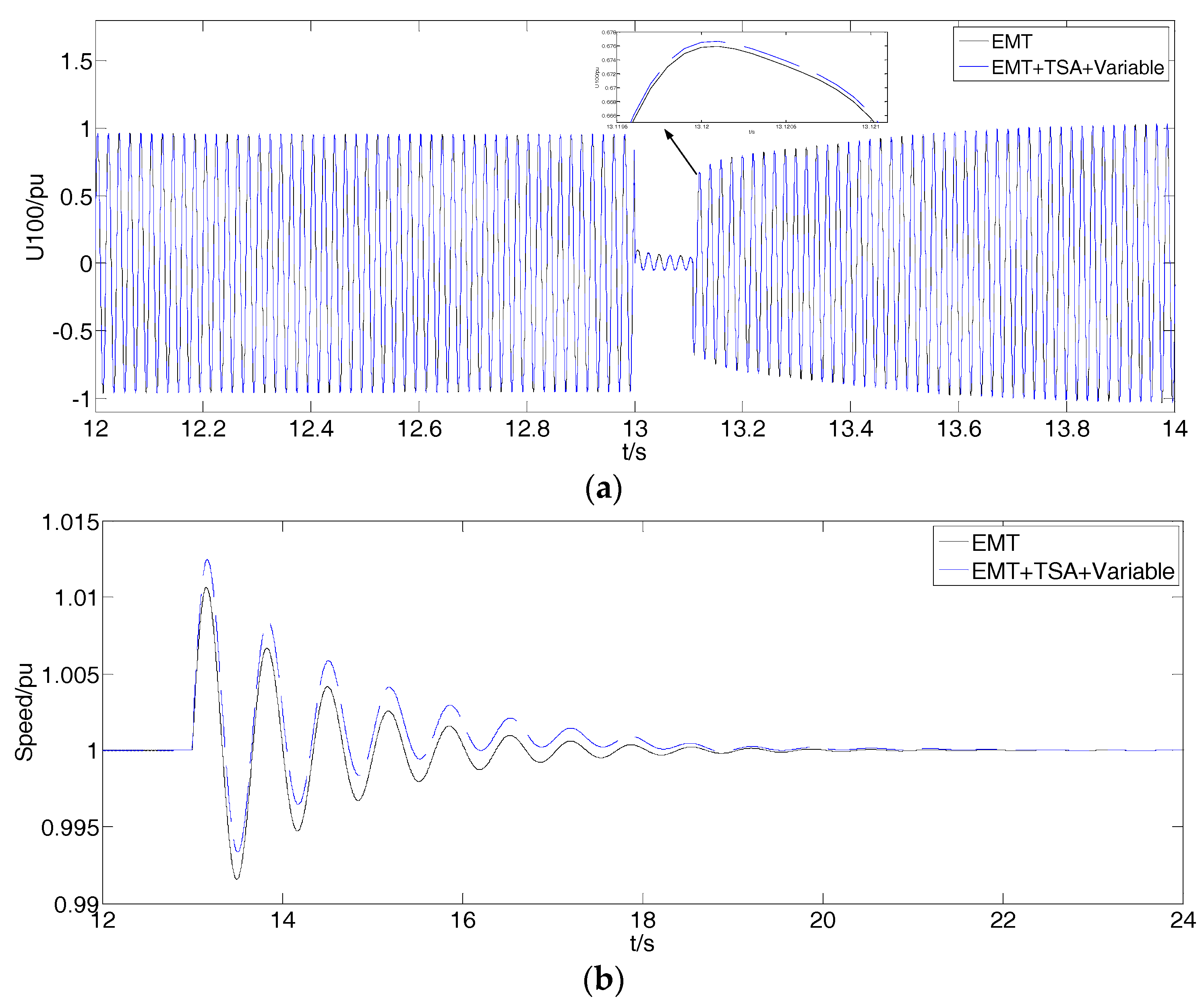
Sub-network 6 and its affiliated area (sub-networks 4, 5, 8, and 11) performs EMT simulation, and other parts perform TSA simulation. A 100 ms three-phase fault is applied to bus 23. The phase A voltage of bus 23 and the rotor speed of the generator at bus 25 are as shown in
Figure 5.
It can be seen from
Figure 5 that the hybrid simulation with the electromagnetic sub-network while using a Norton equivalent on the TSA side is closer to the EMT reference curve than the hybrid simulation using the current source equivalent. That is, the accuracy of the hybrid simulation is improved. It is proven that the method of obtaining the Norton equivalent of an electromagnetic sub-network on the TSA side is effective.
6.2.2. Verification of Variable Area of Interest and Application
To illustrate the effectiveness of the proposed hybrid real-time simulation method, two methods are designed for comparison: full EMT simulation, hybrid real-time simulation proposed in this paper. The hybrid real-time simulation method that is proposed in this paper is represented by the symbol EMT + TSA + Variable. Only the test results of two cases are given.
- a.
Case One
Sub-network 7 and its affiliated area (sub-networks 2, 4, 8, 9, and 13) performs EMT simulation, and other parts perform TSA simulation. A 100 ms three-phase fault is applied to bus 37. The phase A voltage of bus 37 and the rotor speed of the generator at bus 34 are as shown in
Figure 6.
- b.
Case Two
It can be seen from
Figure 6 that the system basically reaches steady state at
t = 12 s, and the object that performs EMT simulation can be changed at this time. Occurring at
t = 12 s, sub-network 20 and its affiliated area (sub-networks 18, 19, 23, 24, 26, and 25) performs EMT simulation and other parts perform TSA simulation. A 100 ms three-phase fault is applied to bus 100. The phase A voltage of bus 100 and the rotor speed of the generator at bus 100 are as shown in
Figure 7.
Figure 6 and
Figure 7 show case one and case two are continuous in time.
Figure 7 demonstrates that the waveform of the phase A voltage of bus 100 and the waveform of the rotor speed of the generator at bus 100 can maintain continuity when the area of EMT simulation is changed. This is because the system basically reaches steady state at
t = 12 s, and the EMT model and the TSA model of the same sub-network at steady state are equivalent. Through analyzing the simulation results, it can be seen that, although a serious three-phase short-circuit fault occurs at the boundary of the area of interest, the average difference [
31] of the voltages at the fault points and the average difference of rotor speed are all within 0.05 pu. It is proven that the proposed method can ensure that the area of EMT simulation is flexibly changed and meets the requirements of simulation accuracy.


