1. Introduction
With the explosive application of high-power equipment promoted by steady development of AC drive systems, applications of multiphase motor drive systems (MMDS) which are popular in high precision and extreme reliability occasions, have been growing dramatically in recent years [
1,
2,
3]. Compared with conventional three-phase drive systems, in which voltage and current sharing always suffer accidents caused by series-parallel power devices, MMDS possesses notable advantages of lower torque ripple, higher fault tolerance and reliability. Meanwhile, accessibility to more phases enhances the freedom of the motor control strategy. Besides, the fundamental and harmonic components can be handled by space vector decoupling. The harmonic component control can be managed flexibly by a harmonic sub-plane, further improving the comprehensive performance of multiphase motors. Consequently, in-depth study on driving techniques of MMDS has vital theoretical and practical significance for high-power industrial applications, ranging from electric and hybrid electric vehicles to electric ship propulsion, and from locomotive traction to “more-electric” aircraft.
As a prominent MMDS, dual Y shift 30° six-phase motor (DYSM) has gained widespread attention and representative application in high-power yet energy-effective fields, such as electric locomotive traction, ship electric propulsion, wind power generation, etc. [
4,
5,
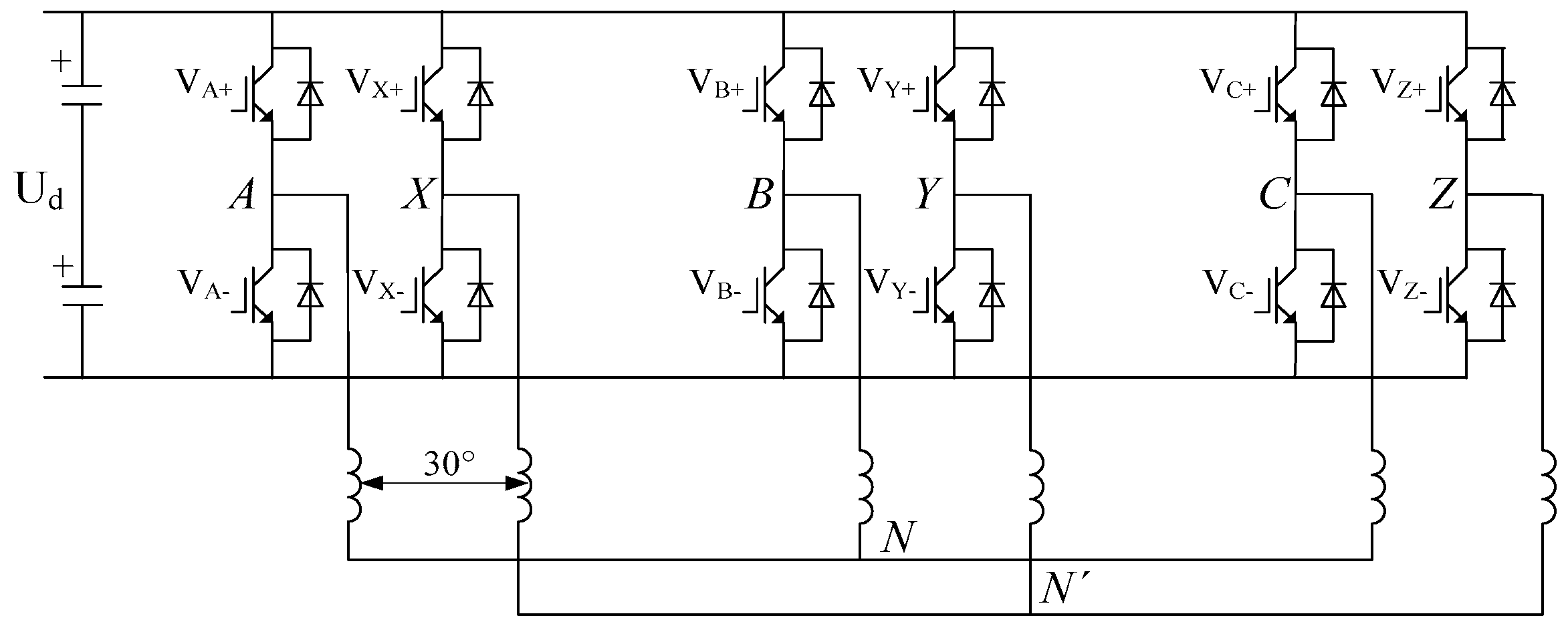
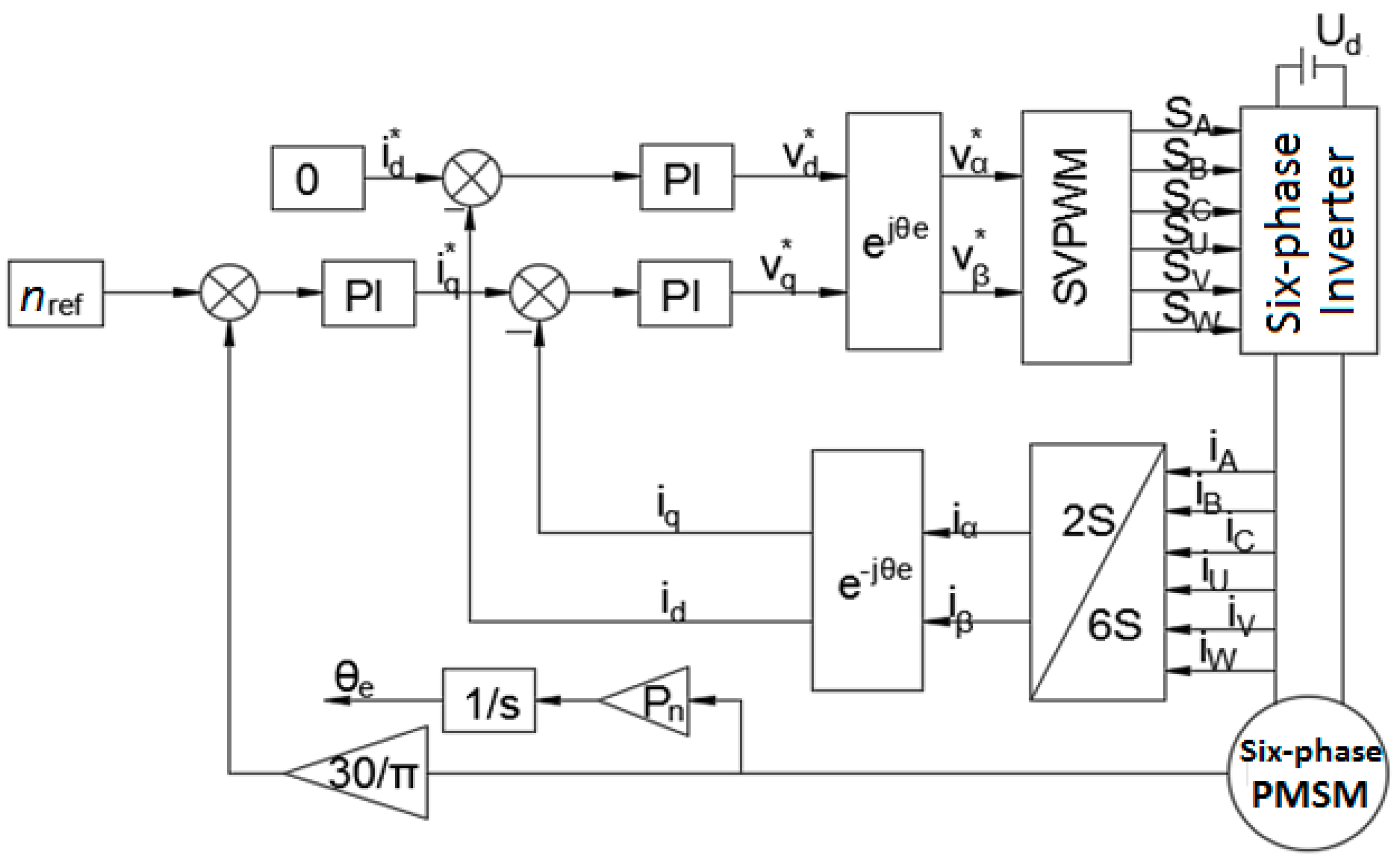
6]. The stator of a DYSM has an irregular but delicate structure. As shown in
Figure 1, the asymmetric six-phase windings of a DYSM are constructed with two sets of three-phase windings, which are arranged with a 30° spatial electrical angle displacement. This special structure brings the following three typical advantages: (1) With the asymmetric six-phase winding, lower-order harmonic components of the magnetic motive force can be effectively eliminated; (2) With double the number of winding phases, higher power can be transmitted on the same voltage or current level; (3) Continuous operating of DYSMs under phase-deficient conditions is possible. These advantages are highly beneficial to green power and sustainable energy-saving.
Given a determined inverter topology, a modulation strategy is extremely significant to improve the performance of a certain motor system [
7,
8,
9]. It can be evidently investigated that, the space vector pulse width modulation (SVPWM) is the most widely applied scheme. SVPWM has attractive flexibility for optimizing switching waveforms and is convenient to implement on embedded processors [
10,
11], as well as its operational advantages over carrier-based techniques (i.e., low total harmonic distortion, high efficiency and voltage available in the DC-link) [
12].
Generally, six-phase SVPWM is implemented by two basic approaches. One is vector classification control, which treats the six-phase motor as two independent three-phase motors with a phase difference of 30°, and then separately adopts three-phase SVPWM. The other, named vector space decomposition (VSD) control, is based on space vector decoupling techniques [
13]. With regard to this method, except for magnifying the fundamental voltage, the stator harmonic voltage should be cautiously considered and completely suppressed. The relationship, respective features, and recommended applications of these two control methods have been extensively investigated in [
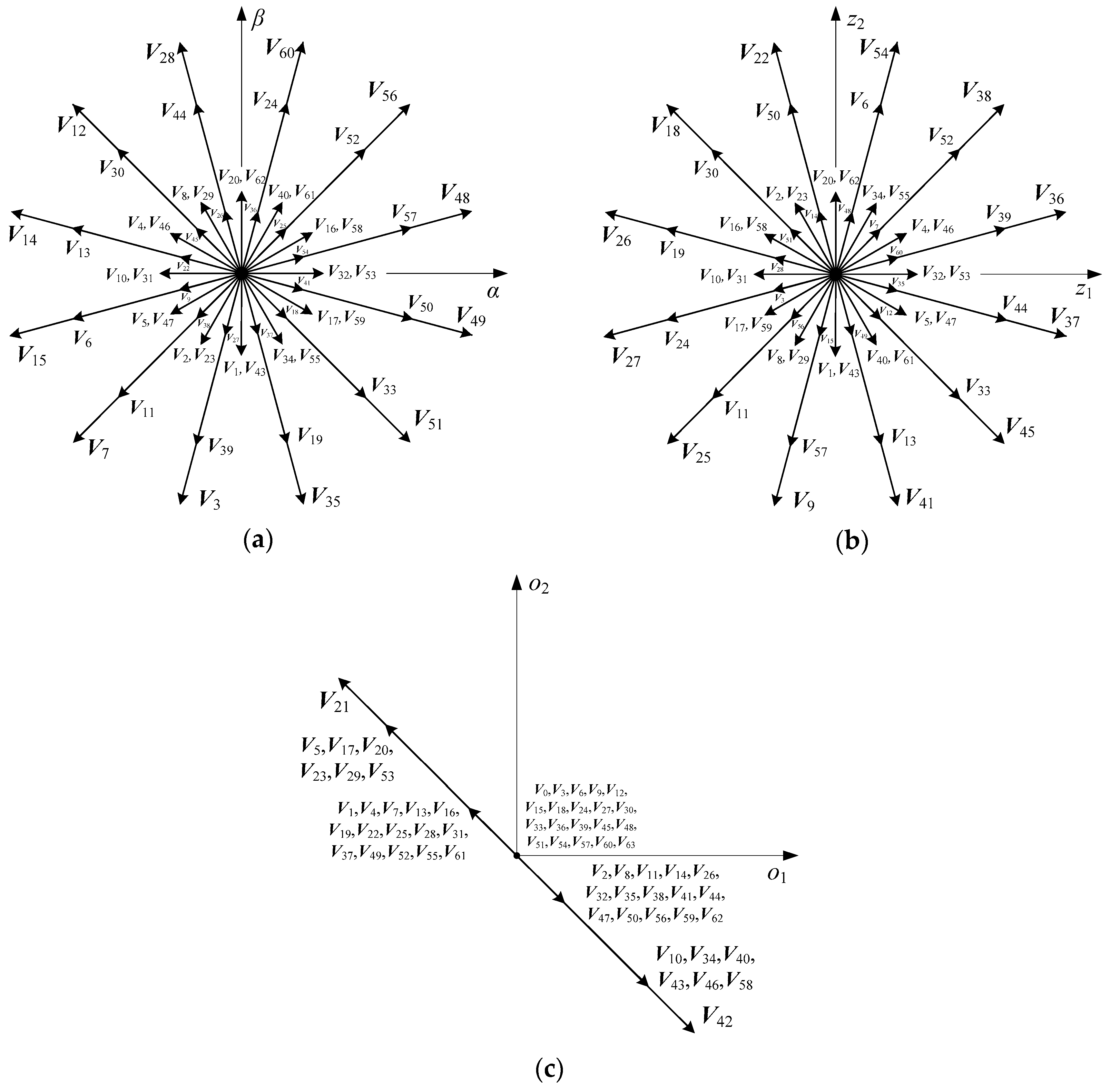
14]. This paper focuses on the latter one. As shown in
Figure 2, 64 phase voltages corresponding to 64 switching states of an inverter are respectively mapped to three orthogonal coordinate sub-planes: fundamental sub-plane (
α-β sub-plane), harmonic sub-plane (
z1-
z2 sub-plane) and zero-sequence sub-plane (o
1-o
2 sub-plane). Then, 64 voltage vectors are generated correspondingly. The
α-β sub-plane contains fundamental waves and
t1th harmonic components, the
z1-
z2 sub-plane contains
t2th harmonic components, and the o
1-o
2 sub-plane contains
t3th harmonic components, where
t1 = 12k ± 1,
t2 = 12k ± 5,
t3 = 12k ± 3, k = 0,1,2,3,…, The harmonics on the
z1-
z2 sub-plane make null contribution to motor electromechanical energy conversion but result in energy wastage, which should be suppressed as far as possible.
The past two decades have witnessed numerous developments of state-of-the-art VSD control strategies, they mainly treat the machine as an integral six-phase system [
15,
16,
17,
18,
19,
20]. Supposing the coordinate transformation matrix follows the principle of amplitude equivalence, the 64 fundamental vectors exhibit five different magnitudes on the
α-β sub-plane: 0.644U
d (large vectors), 0.4714U
d (medium vectors), 0.2066U
d (small vectors), 0.1725U
d (ultra-small vectors), and 0 (zero vectors), where U
d denotes the DC-bus voltage of inverter. In [
15], the traditional three-phase SVPWM was directly applied in six-phase motor systems, this method could track reference vectors on
α-β sub-plane precisely, but leaving the harmonic elements on
z1-
z2 sub-plane unconsidered. Innovatively, a classical VSD-base SVPWM strategy (hereafter is referred to C-SVPWM) was proposed to limit the 5th, 7th, 17th, 19th…, harmonic elements [
16]. The key idea is that the
α-β sub-plane is divided into 12 equal but non-overlapping sectors, and in each sector, five vectors (i.e., four adjacent large vectors and one zero vector, where their vector synthesized results on the
z1-
z2 sub-plane equals to zero) are selected to track the reference vectors. Consequently, the harmonic voltages on the
z1-
z2 sub-plane are completely suppressed. The motor performance on current, torque and speed are satisfactory, but its fundamental amplitude of the stator winding voltage is limited below 0.57735U
d.
A mid-vector-based SVPWM strategy (hereafter is referred to M-SVPWM) was first proposed in [
17]. Arbitrary three adjacent large vectors (where their vector synthesized results on the
z1-
z2 sub-plane equals to zero) are chosen from
α-β sub-plane to synthesize one mid-vector with the fixed magnitude and position. Then 12 mid-vectors with equal magnitude and 30° phase difference can be obtained, and the reference vector is synthesized by using the 12 mid-vectors and one zero vector. Since the essence of M-SVPWM is the same as that in [
16], the limitation of 0.57735U
d cannot be broken theoretically. To overcome this barrier, a six-phase pre-synthetic-vector-based SVPWM strategy (hereafter is referred to PS-SVPWM) was proposed in [
18]. Three arbitrary adjacent large vectors (where their vector synthesized results on the
z1-
z2 sub-plane can be allowed not equal to zero) are chosen from
α-β sub-plane to synthesize one variable-magnitude but position-invariant vector, which names pre-synthesized vector. Then a total of 12 pre-synthetic vectors with variable-magnitude and 30° phase difference can be obtained. And the reference vector is synthesized by using the 12 pre-synthetic vectors (but without zero vector). In PS-SVPWM, the voltage values of the fundamental amplitude of the stator winding can be as many as 2U
d/π, and the harmonic voltage suppression has been highly emphasized on the
z1-
z2 sub-plane. Thus, the comprehensive performance is improved to a large extent. However, the suppression degree of the harmonic voltage could be further strengthened as minimizing operation is absent among its vector synthesized results on
z1-
z2 sub-plane. Based on the aforementioned achievements, an optimal modeled six-phase SVPWM is proposed in this paper (hereafter is referred to OM-SVPWM). After four adjacent large vectors are selected from each sector of the 12 pre-divided sectors on the
α-β sub-plane, an optimization model is constructed to optimally determine activation durations of the four selected vectors. In the model, the optimization objective is to minimize vector synthesized results on the
z1-
z2 sub-plane of the four selected vectors, and the constraint condition is that vector synthesized result on the
α-β sub-plane of the four selected vectors satisfies a reference vector. In practical engineering applications, given every magnitude and position of the reference vector, the general central path following algorithm (GCPFA) [
21] is adopted to obtain the optimum solution in real time. The rest of this paper is organized as follows:
Section 2 briefly introduces the theory preliminaries of two traditional SVPWM strategies.
Section 3 elaborates the theory of the proposed OM-SVPWM in detail. Theoretical simulation and real-world experiments are illustrated and discussed in
Section 4.
Section 5 finally concludes this paper.
2. State-of-the-Art Six-Phase SVPWM Strategies
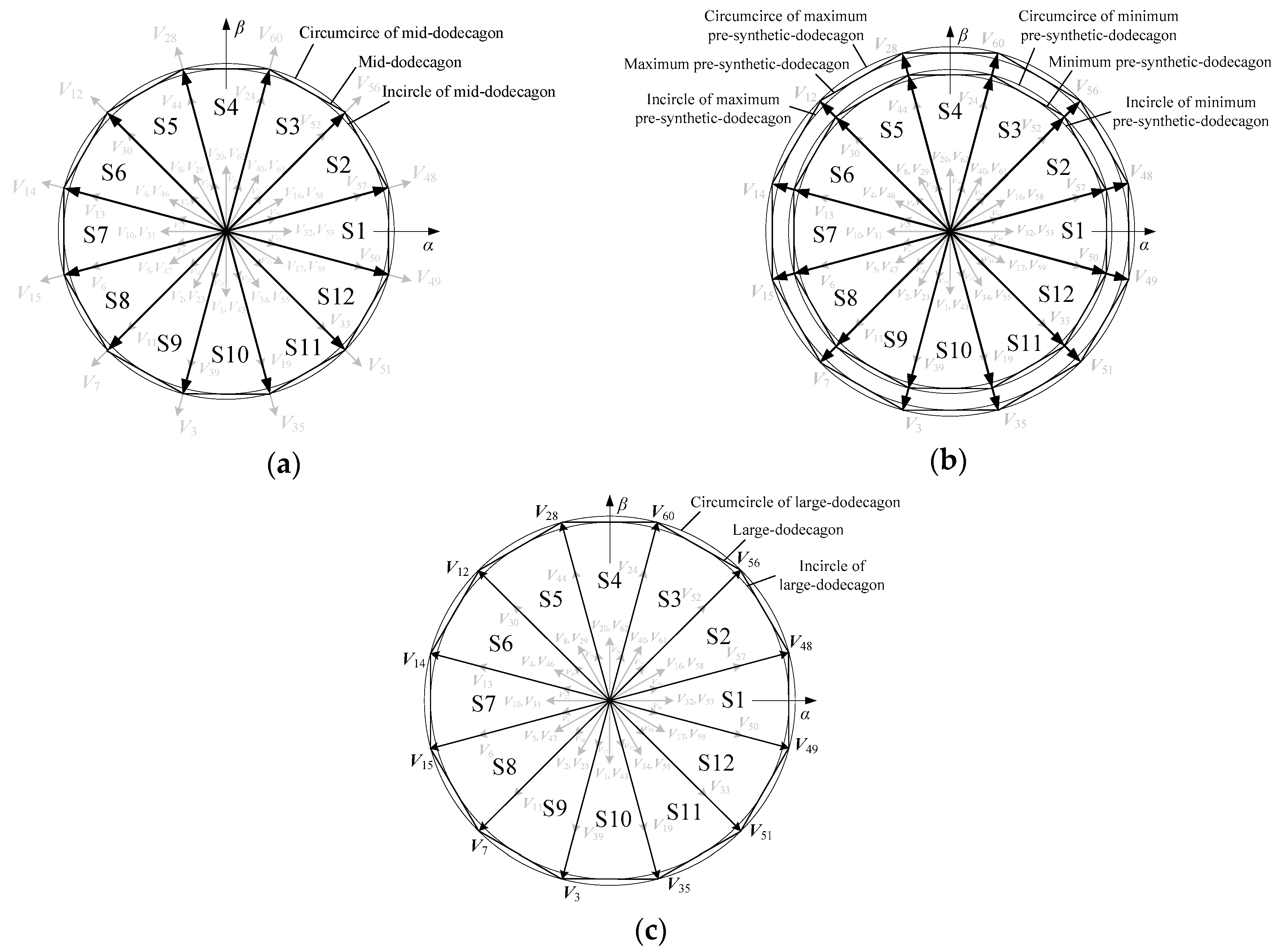
In the M-SVPWM, the 12 mid-vectors on the
α-β sub-plane form a regular 12-sided shape, which is called the mid-dodecagon. Its circumcircle radius
Rm is 0.5977U
d, and incircle radius r
m is 0.57735U
d. With 12 mid-vectors as the boundary, the
α-β sub-plane is divided into 12 sectors, expressed by S1–S12, as shown in
Figure 3a. In each sector, the reference vector
V* is synthesized by using two mid-vectors (i.e., the mid-vector at the initial side of the sector and the mid-vector at the terminal side of the sector) and one zero vector. Since two mid-vectors correspond to four adjacent large vectors, the reference vector is finally synthesized through five vectors (i.e., four adjacent large vectors and one zero vector). The activation durations
t1,
t2,
t3,
t4,
t0 of these five vectors in a switching period
Ts are:
where
V* is the magnitude of reference vector, and
θ is the position of reference vector (i.e., the angle between the reference vector and the mid-vector at the initial side of the sector, 0° ≤
θ ≤ 30°).
According to (1), when the value of V* exceeds the radius rm (i.e., 0.57735Ud) of the inscribed circle, the activation duration of zero vector t0 will appear negative value, so the value range of V* is 0 ≤ V* ≤ 0.57735Ud. Within this span, the synthesis result of the five vectors on the α-β sub-plane is equal to the reference vector, and the synthesis result is equal to zero on the z1-z2 sub-plane.
The PS-SVPWM can make the value of
V* exceed 0.57735U
d. As shown in
Figure 3b, the PS-SVPWM on the
α-β sub-plane form a series of regular 12-sided shapes, called the pre-synthetic-dodecagons. The minimum pre-synthetic-dodecagon coincides with the mid-dodecagon, and the maximum pre-synthetic-dodecagon coincides with the 12-side shape formed by the 12 large vectors. Thus, the maximum circumcircle radius R
p is 0.644U
d, and the maximum incircle radius r
p is 0.622U
d. With 12 pre-synthetic vectors as the boundary, the
α-β sub-plane is divided into 12 sectors, which are represented by S1–S12. In each sector, the reference vector
V* is synthesized by two pre-synthetic vectors (i.e., the pre-synthetic vector at the initial side of the sector and the pre-synthetic vector at the terminal side of the sector), and zero vectors are no longer involved in the synthesis. Since two pre-synthetic vectors correspond to four adjacent large vectors, the reference vector is ultimately synthesized from four adjacent large vectors. The activation durations
t1,
t2,
t3 and
t4 of the four vectors in one switching period
Ts are:
where
a is a proportional coefficient, which varies with the magnitude and position of reference vector;
Ta is the activation duration of the pre-synthetic vector at the initial side of the sector, which varies with the position of reference vector;
Tb is that at the terminal side of the sector. The specific expressions of the three parameters are as follows:
According to (2) and (3), the span of V* is 0.57735Ud ≤ V* ≤ 0.622Ud. In this span, the synthesis result of the four vectors on the α-β sub-plane is equal to the reference vector, while the synthesis result on the z1-z2 sub-plane is not equal to zero.
The above two methods are based on the six phase SVPWM of the non-optimized model. M-SVPWM can make the synthesis result of z1-z2 sub-plane to zero, but the value of V* can only reach 0.57735Ud at most; by contrast, the value of V* can reach 0.622Ud at most, but the synthesis result of z1-z2 sub-plane is not equal to zero. Therefore, in order to minimize the synthesis result of z1-z2 sub-plane and at the same time to maximize the value of V* up to 0.622Ud, the following six-phase SVPWM method based on optimization model is proposed.
3. Six-Phase SVPWM Based on Optimization Model
As shown in
Figure 3c, the 12 large vectors on the
α-β sub-plane form a normal 12-sided shape, called the large-dodecagon. The circumcircle radius
RL is 0.644U
d, and the incircle radius
rL is 0.622U
d. By using 12 large vectors as the boundary, the
α-β sub-plane is divided into 12 sectors, which are represented by S1–S12. In each sector, the reference vector
V* is synthesized by four adjacent large vectors, and zero vectors do not participate in the synthesis. The optimization model is as follows:
where
Vh is the hth vector from four large vectors;
Th is the activation duration of the hth large vector and is the design variable;
is the synthesis result of four large vectors;
is the magnitude of the synthesis result of four large vectors;
is the sum of the four activation durations, which is equal to the switching period
Ts.
The objective function of the (4) shows that the smaller
, the more effective suppression of the harmonic voltage on
z1-
z2 sub-plane. There are three constraints to (4): First,
is equal to the reference vector on the
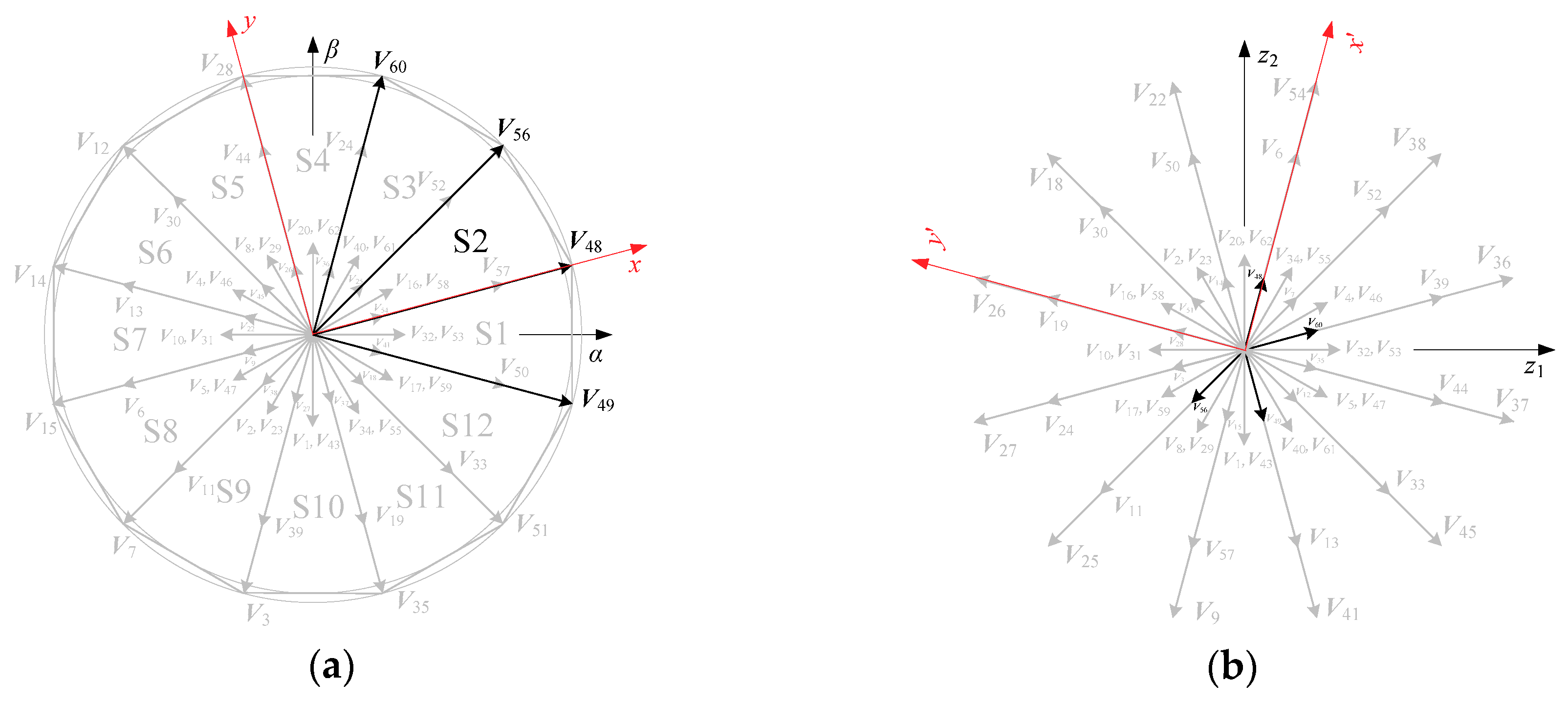
α-β sub-plane; Second, the sum of the four activation durations is equal to one switching period; Third, the activation duration of each large vector is nonnegative. Take sector S2 as an example, the four large vectors are
V49,
V48,
V56,
V60. Then set up a local rectangular coordinate on the sector, where the horizontal axis
x is consistent with the vector
V48 at the initial side of the sector, as shown in
Figure 4a; set up a local rectangular coordinate on the
z1-
z2 sub-plane, where the horizontal axis
x′ is consistent with
V48, as shown in
Figure 4b. Therefore the objective function is:
where
is the square of the projection of the four vectors synthesis result on the horizontal axis
x′, and
is that on the longitudinal
y′.
The concrete expressions for
and
are as follows:
The objective function can be further simplified to:
Turn (8) into a quadratic form about
t49,
t48,
t56 and
t60 as follows:
According (9), the matrix of quadratic form is a positive semidefinite matrix. The constraint condition is:
From (8) to (10), we know that this is a convex quadratic programming (CQP) with equality constraints and inequality constraints. The CQP problem contains two parameters, the magnitude
V* and position
θ of the reference vector, where, 0.57735U
d ≤
V* ≤ 0.622U
d, 0° ≤
θ ≤ 30°. For each specific
V* and
θ, the optimal solution can be obtained by using an optimization algorithm. There are many algorithms for solving the CQP problem, but through the joint debugging of software and hardware, we find that a general central path following algorithm (GCPFA) [
21] can quickly find the exact optimal solution. The situation in other sectors is similar to sector S2, so it is not repeated.
5. Conclusions
In the electromechanical systems composed of a dual Y shift 30° six-phase motor and two-level voltage source inverter, to further suppress the stator harmonic voltages of the motor, a novel six-phase space vector pulse width modulation based on the optimization model (OM-SVPWM) is proposed. Efficient and effective suppression to the voltage (and current) harmonics of stator windings is achieved by innovatively realized the synthesis vectors minimization on the z1-z2 sub-plane.
In the proposed optimization model, four adjacent large vectors are employed on each of 12 sectors of the fundamental sub-plane; the decision variables are the actuation durations of the four vectors; the objective function is the synthesis result of the four vectors on the harmonic sub-plane; and the constraint condition is the synthesis result of the four vectors on the fundamental sub-plane satisfies a reference vector. Essentially, the solving process of this model is a convex quadratic programming (CQP) with equality constraints and inequality constraints. With each specific magnitude and position of the reference vector, an optimal solution is obtained effectively by using a generalized central path tracking algorithm. With this generalized OM-SVPWM model, in addition to achieving intensive harmonic suppression, we realize that the fundamental amplitude of the stator winding voltage breaks through the limitation of 0.57735Ud by boosting the vector synthesized results on α-β sub-plane to a large extent. This is precisely the advantage of the optimization modelling compared with the analytical solution methods.
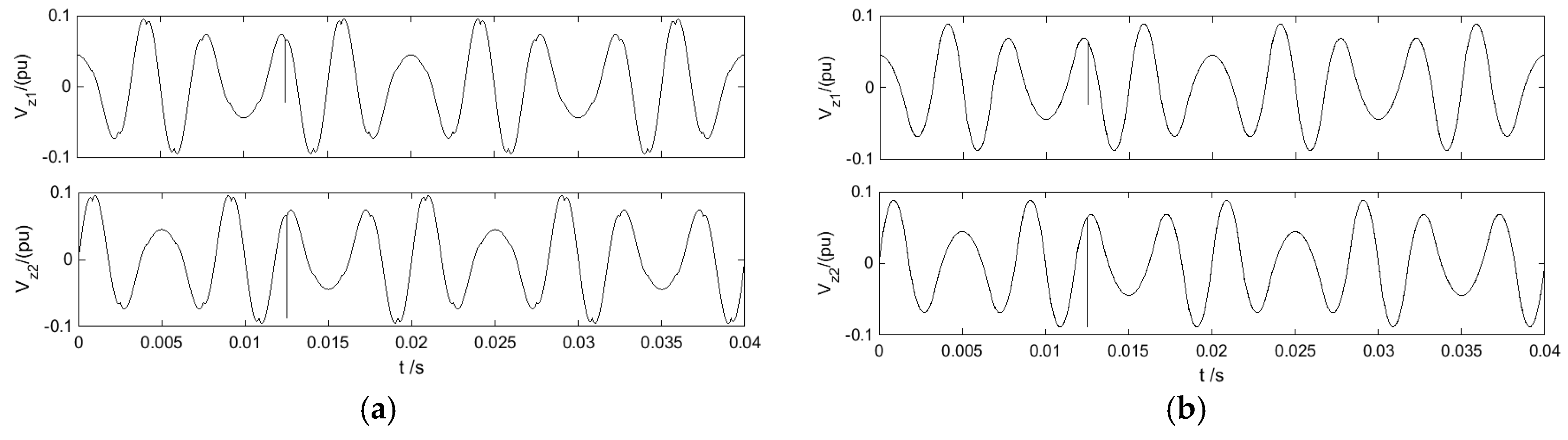
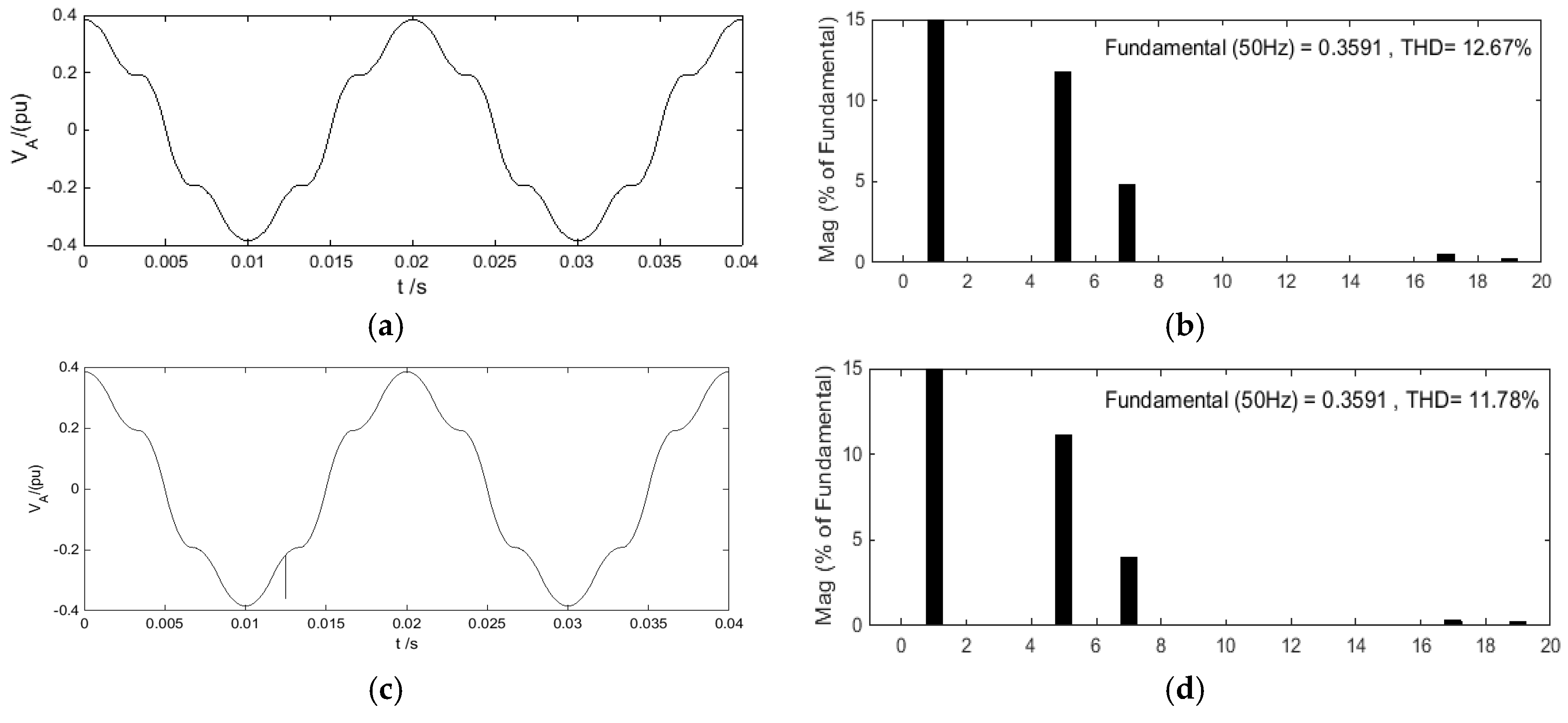
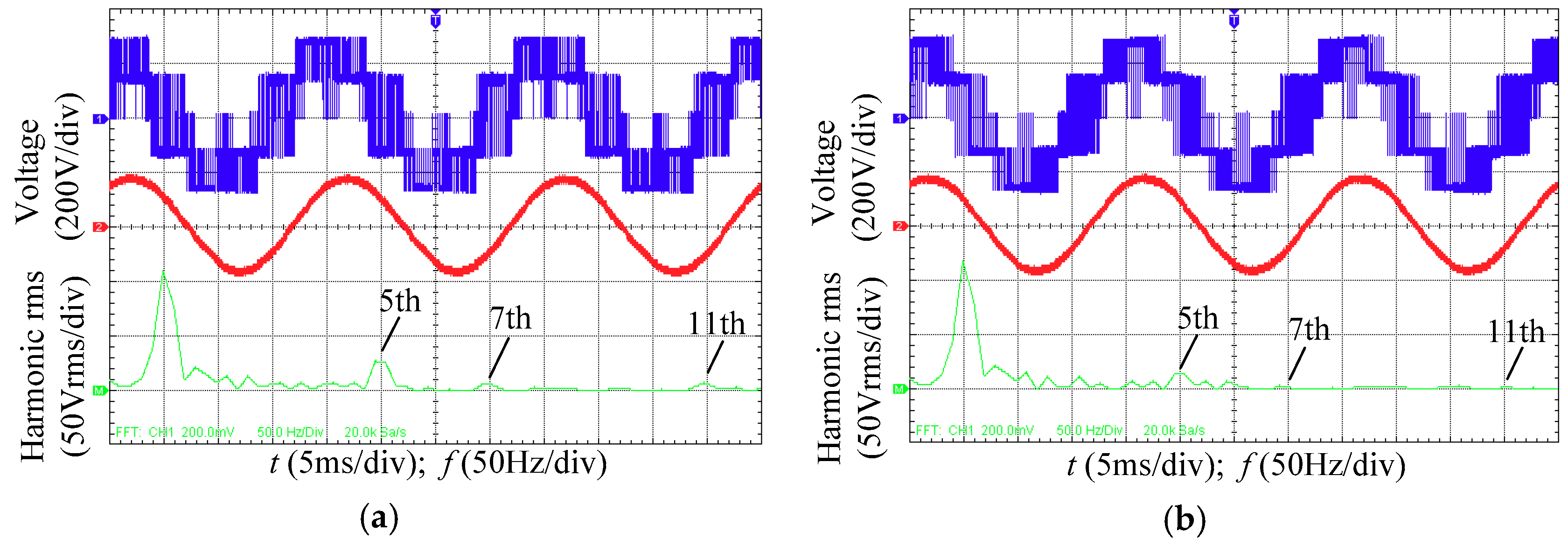
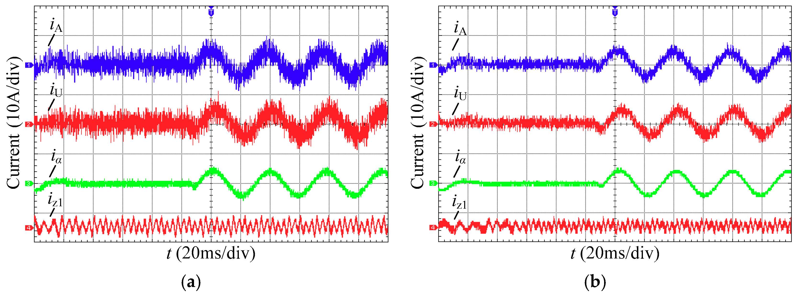
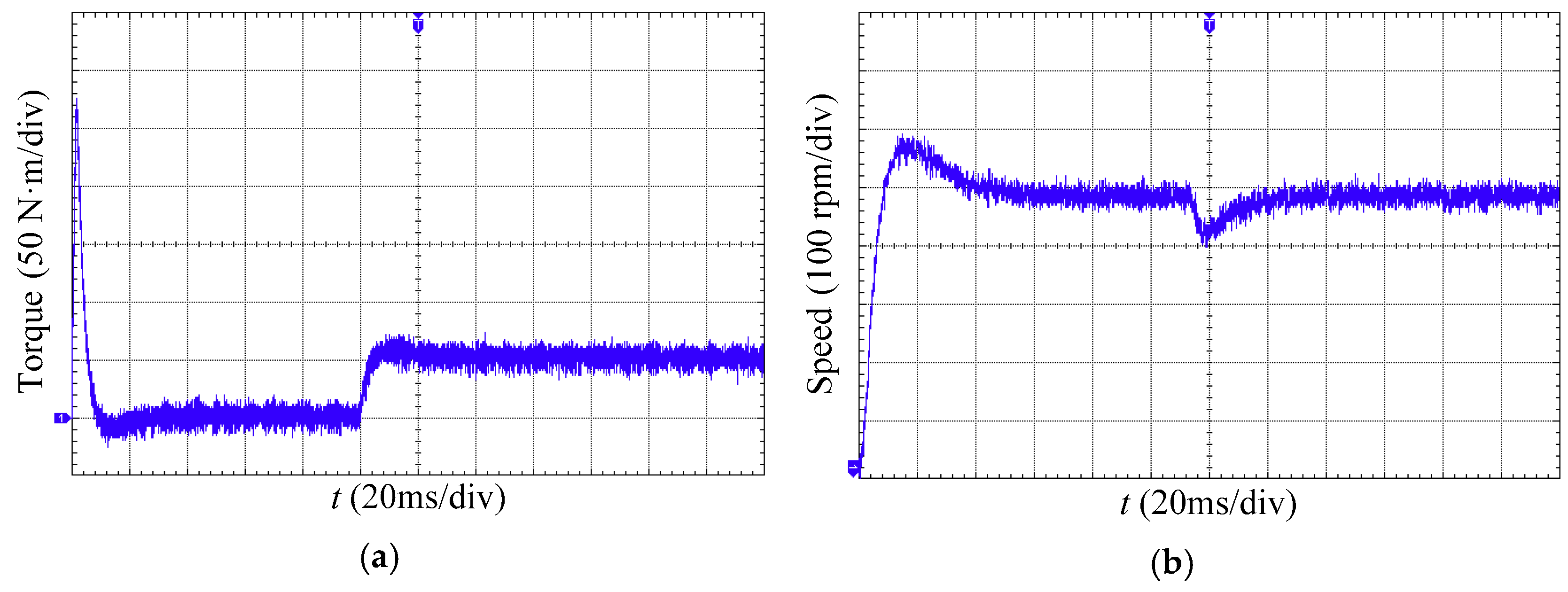
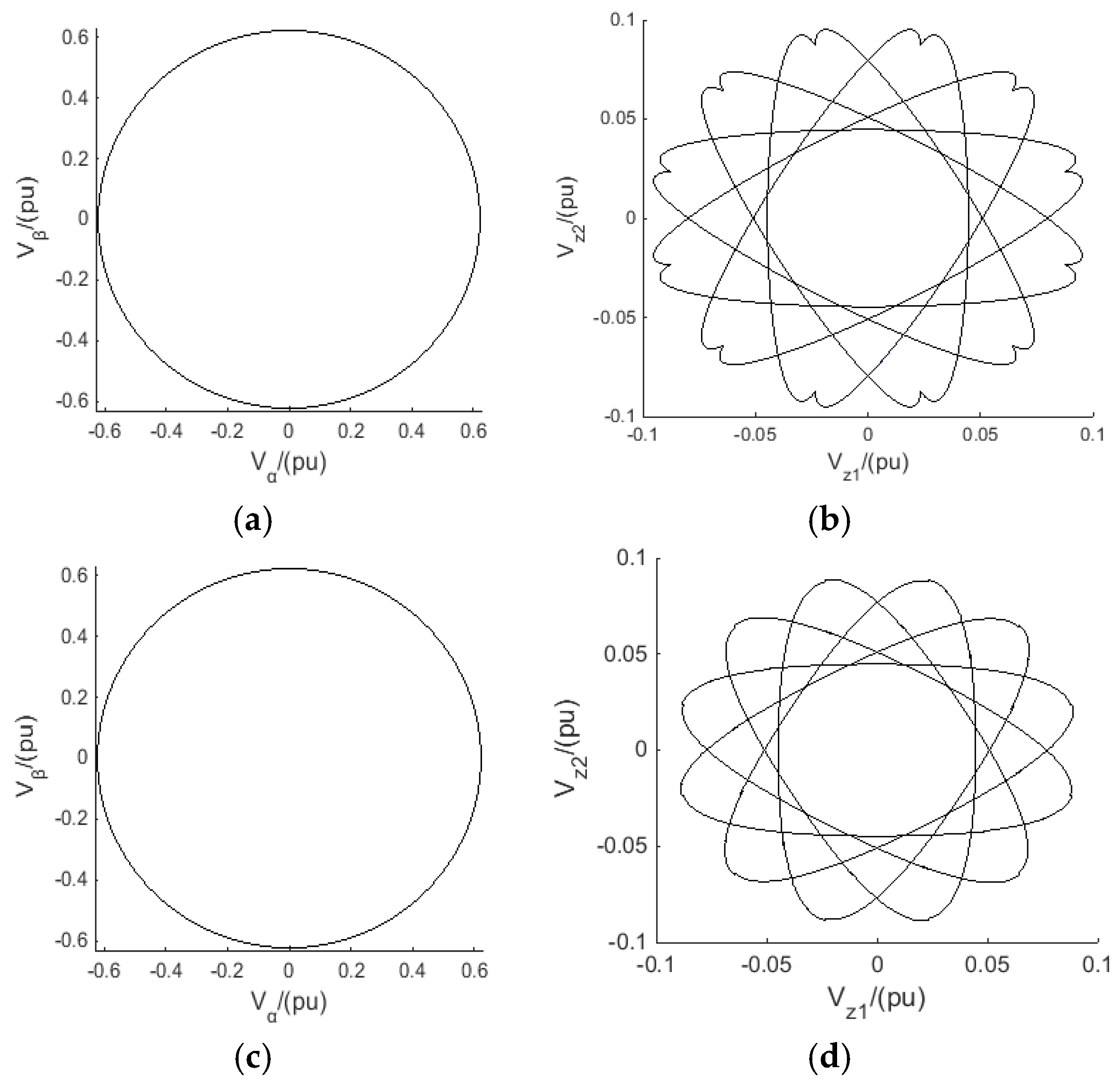
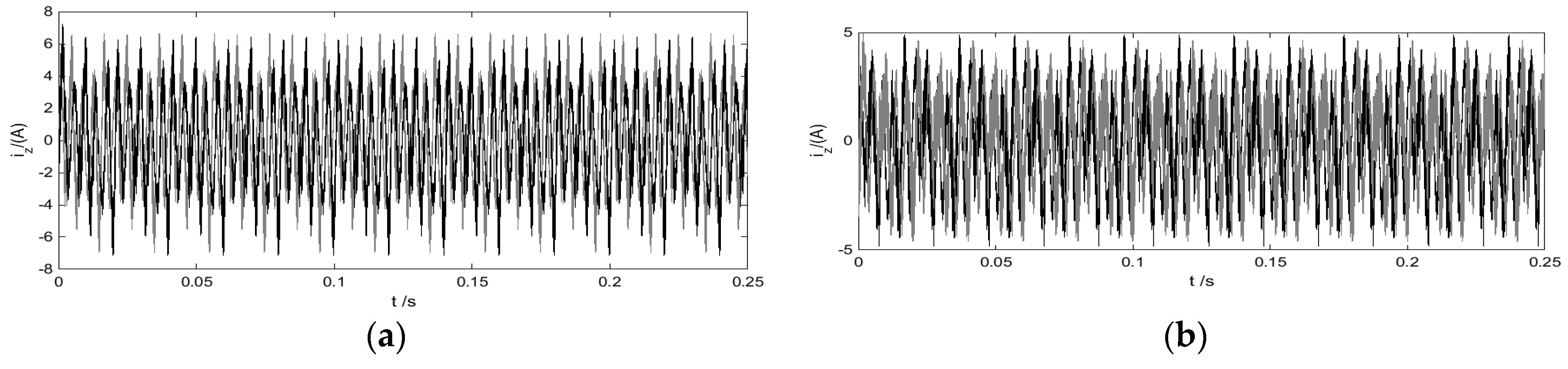
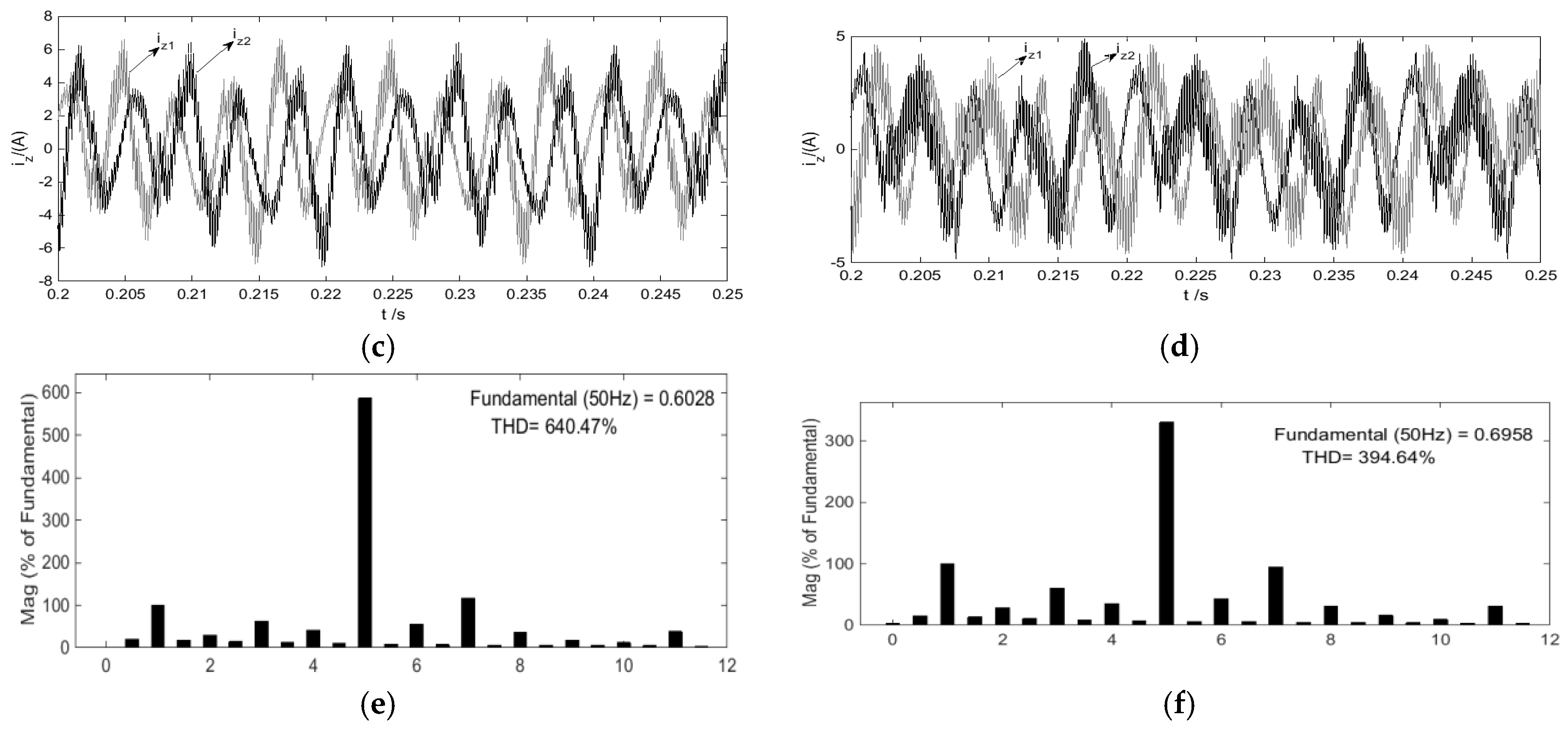
Experimental results from both theoretical simulation and a real-world application indicate the proposed OM-SVPWM performs better than a recent state-of-the-art strategy (PS-SVPWM) in terms of voltage and current harmonic suppression. In the open-loop simulation setup with modulation index m = 0.622, the harmonic voltage on z1-z2 sub-plane by using our OM-SVPWM is 20.51% lower than that of the PS-SVPWM, and the THDu is improved from the 12.67% of PS-SVPWM to 11.78%. In the close-loop simulation setup with motor speed nref = 478 r/min, our OM-SVPWM generates only 4.89 A amplitude of harmonic current while PS-SVPWM suffers 7.12 A, and performs nearly twice better than PS-SVPWM regarding to the THDi, experiencing only 394.64% vs. 640.74%. All these improvements have been witnessed in the actual experiments. In the open-loop experiment, OM-SVPWM experiences evidently lower than PS-SVPWM for all the 5th, 7th and 11th voltage harmonics (5th voltage harmonic: 13.16 Vrms for OM-SVPWM vs. 24.85 Vrms for PS-SVPWM). In the close-loop experiment, our OM-SVPWM performs even 37.56% better than PS-SVPWM on harmonic suppression under the premise of insuring the same synthesized results on α-β sub-plane, with iz1 pulsation amplitude 5.69 A vs. 9.08 A.
Future work will focus on improving the calculation parallelizability to solve the CQP problem of the OM-SVPWM, so as to obtain more precise approximation solution, with the hope of that the proposed method could be further extended to the SVPWM systems of five-phase, nine-phase, twelve-phase and other multi-phase motors.


