Digital Generator Control Unit Design for a Variable Frequency Synchronous Generator in MEA


Abstract
:1. Introduction
- ➢
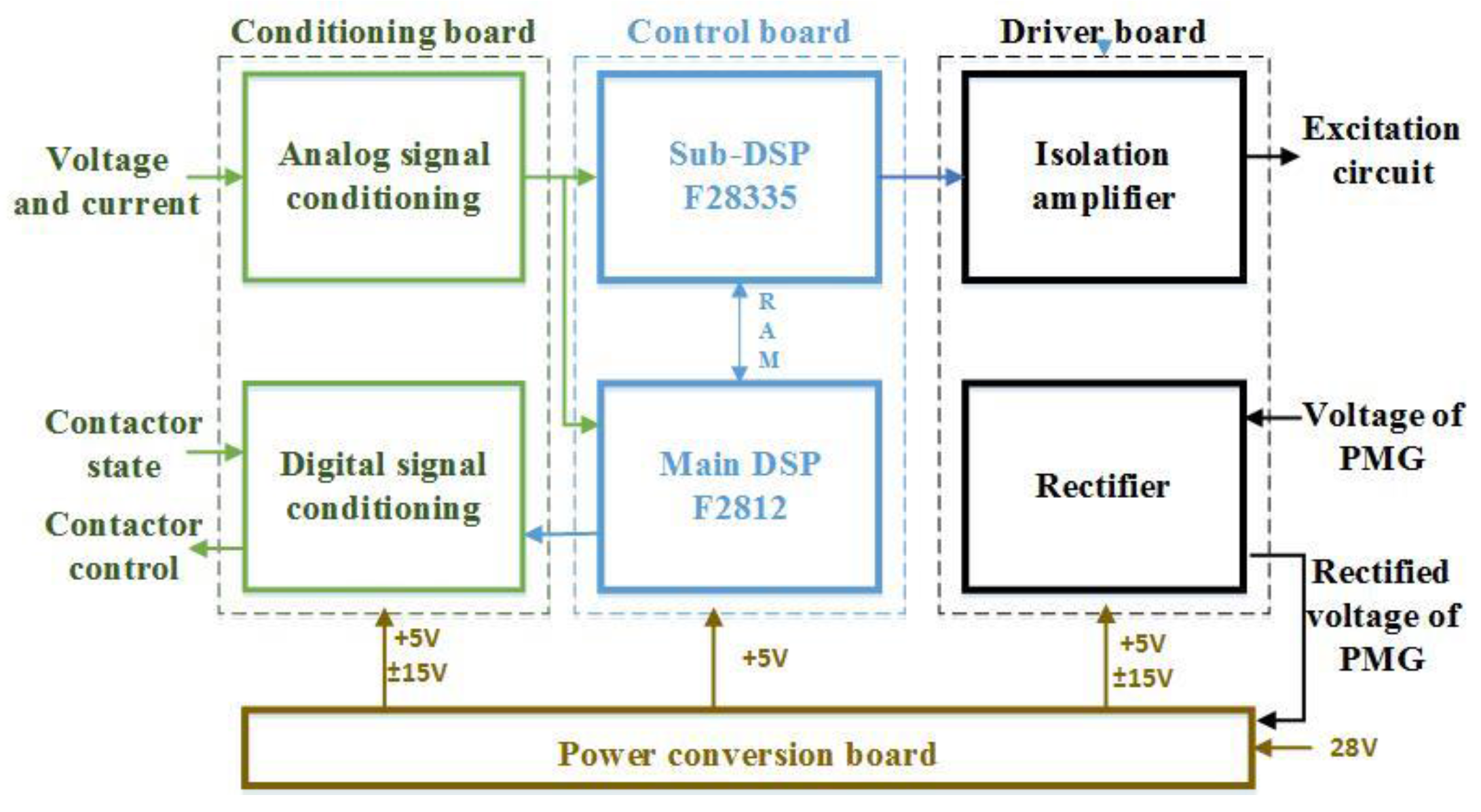
- This paper proposes a dual-DSP system, in which the main-DSP completes protection, communication, and management functions of the system, while the sub-DSP completes generator voltage control and other functions. Dual DSP design can ensure that the system is more reliable, and has better control performance.
- ➢
- The parameters of the PI controller will be changed adaptively according to the frequency, and the voltage regulation accuracy is thus higher than the constant PI controller.
- ➢
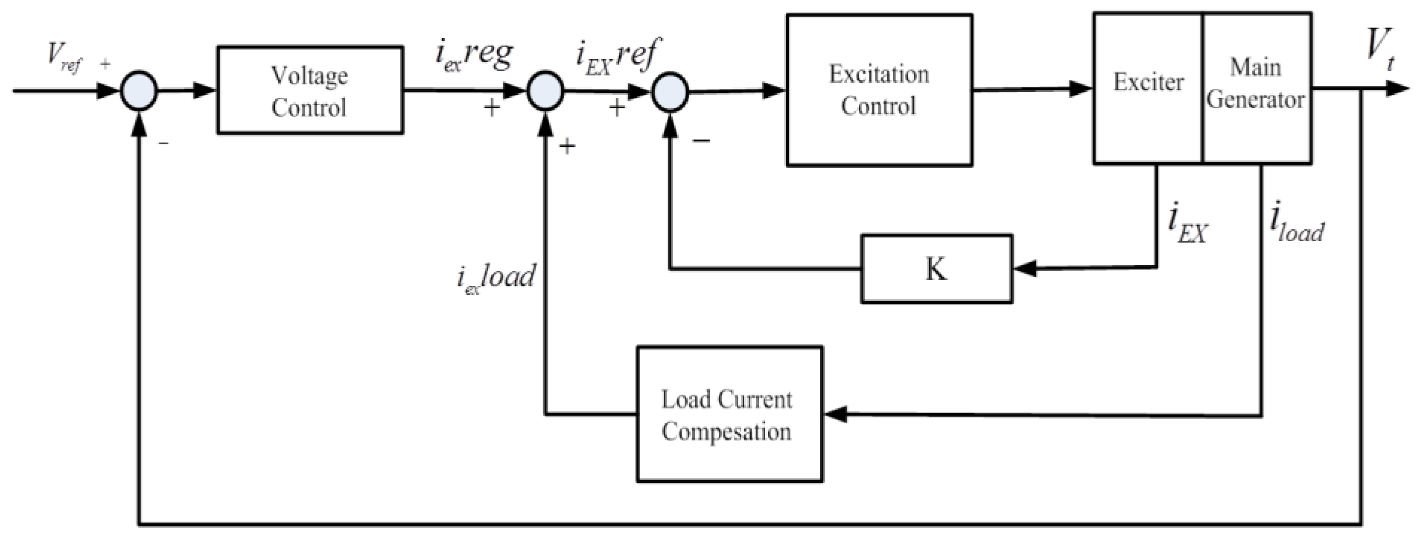
- Moreover, this paper adopts a multi-feedback multi-loop controller structure. The inner loop compensates for the load current, so as to reduce the influence of the load current, enabling the regulator to adapt to a larger scope of working frequency and having better steady and dynamic performance.
2. System Description
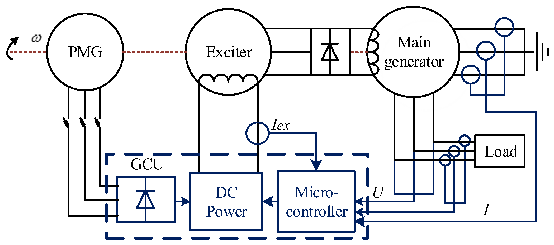
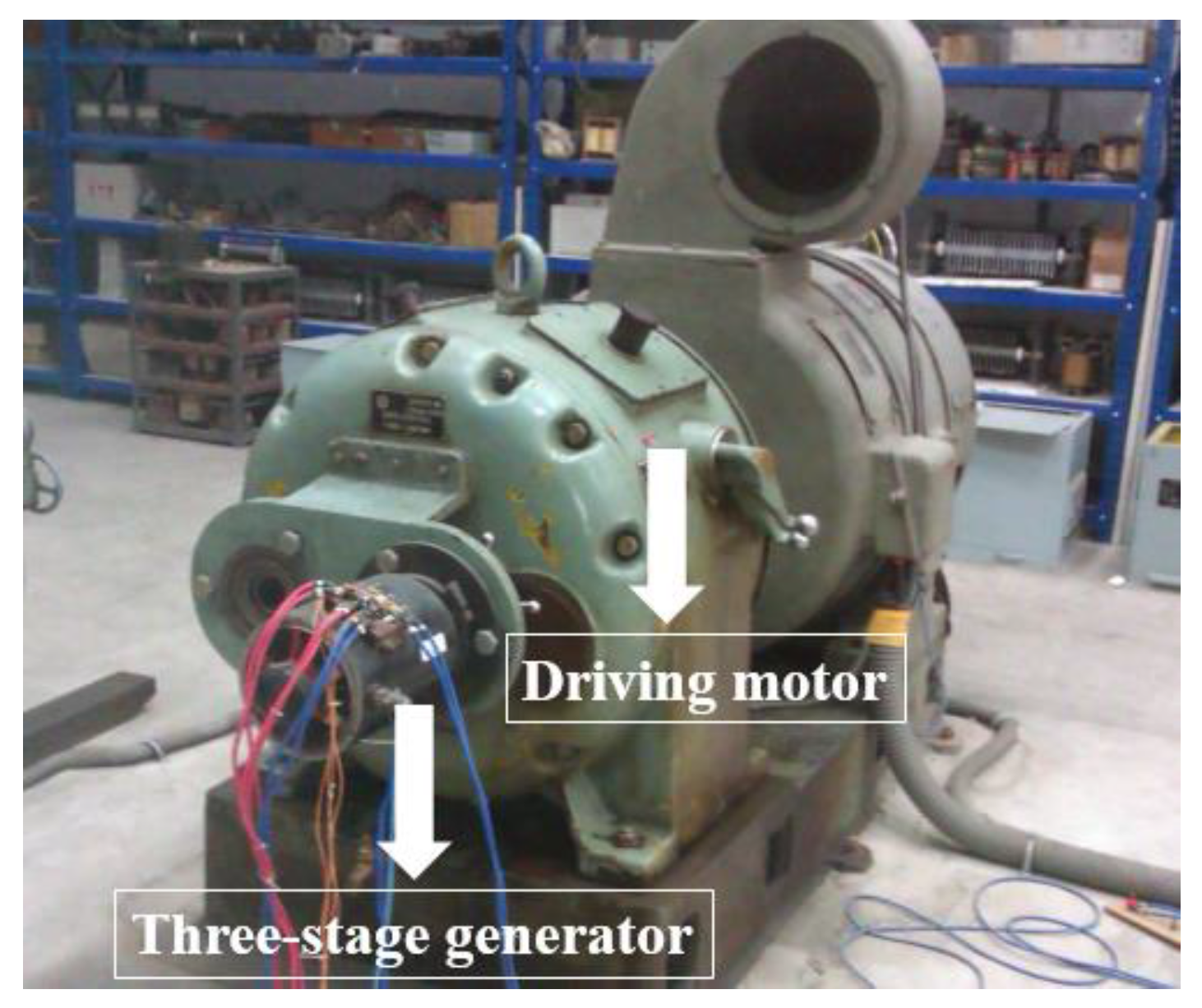
2.1. Three-Stage Generator
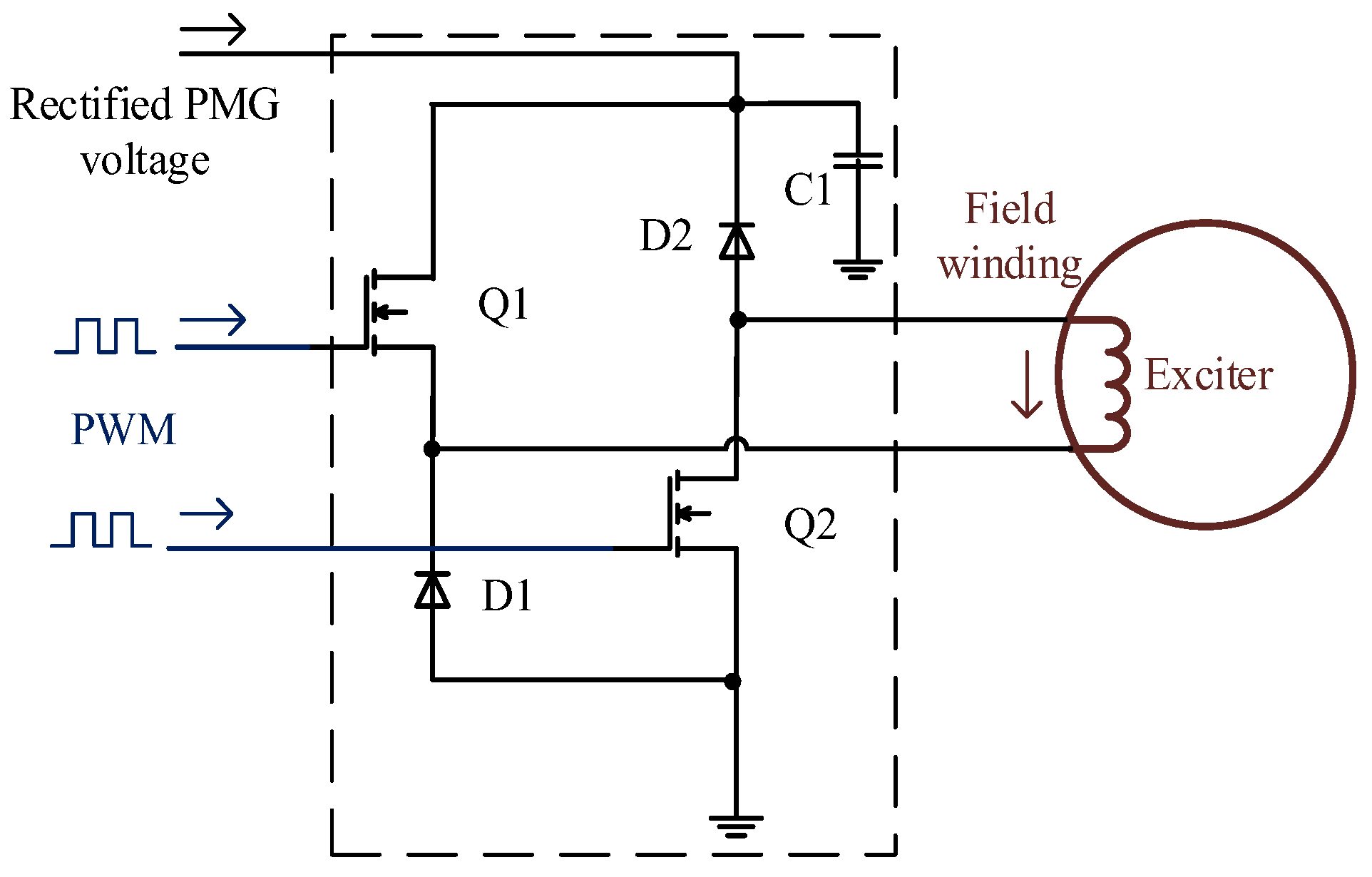
2.2. Internal Structure and Working Principle of GCU
3. Generator Controller Unit Control Method
4. Modeling and Stability Analysis
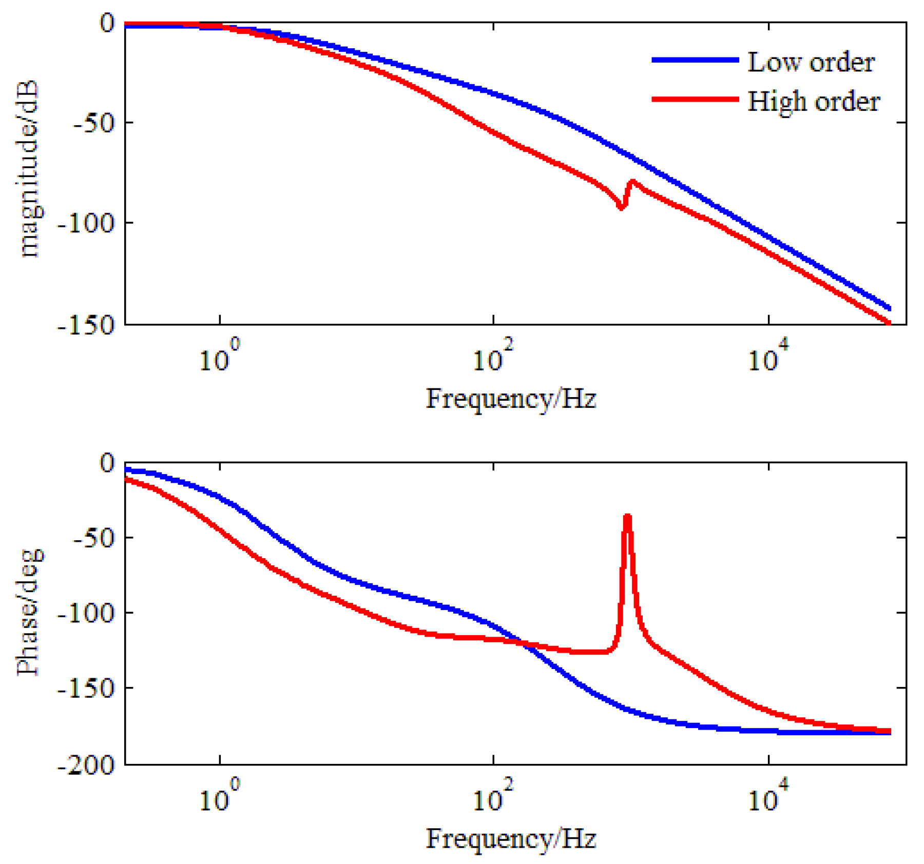
4.1. Three Stage Generator Transfer Function
4.2. Stability Analysis
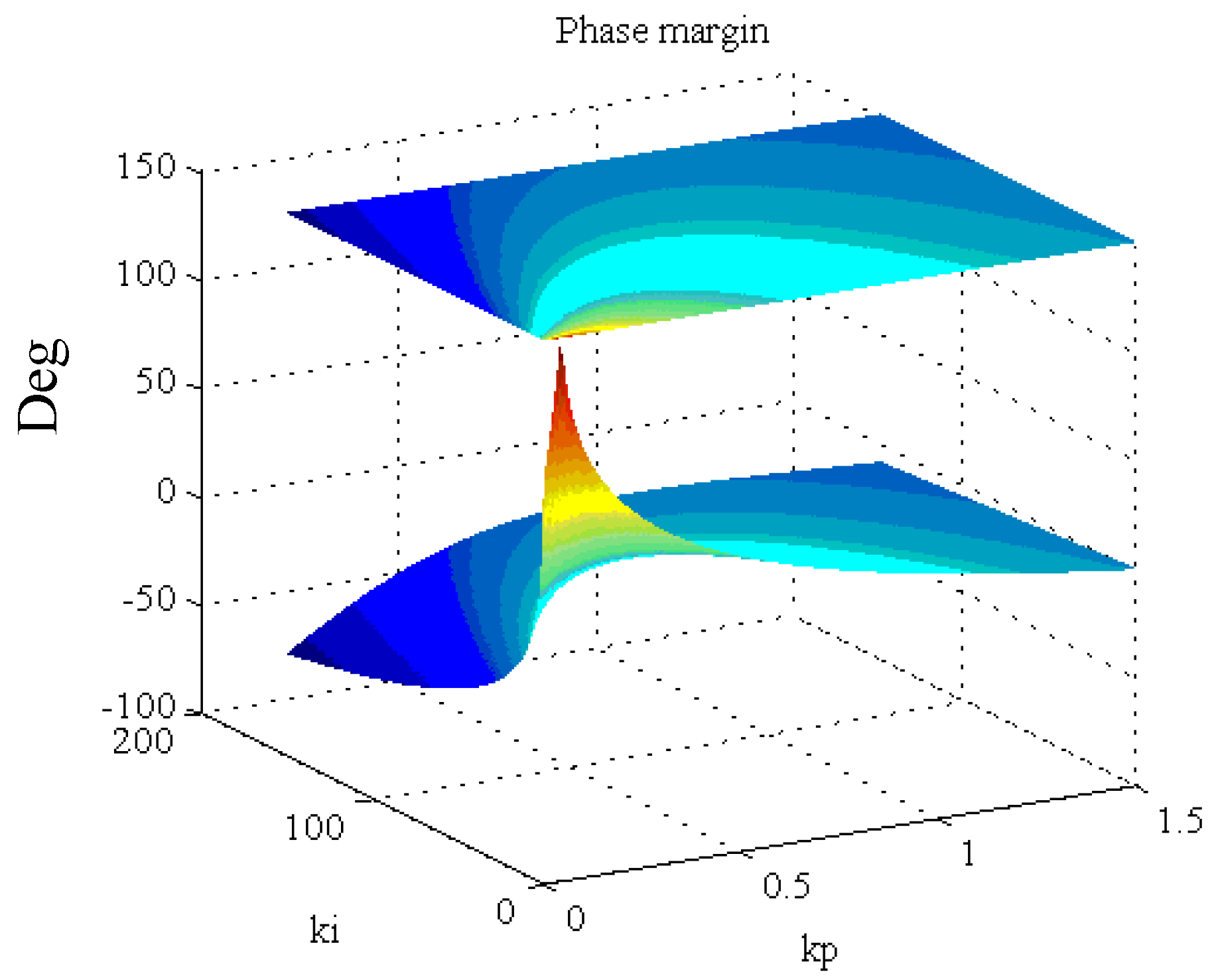
- ➢
- The smaller ki is, the better stability system can get. But there is no linear proportional relationship between kp and stability;
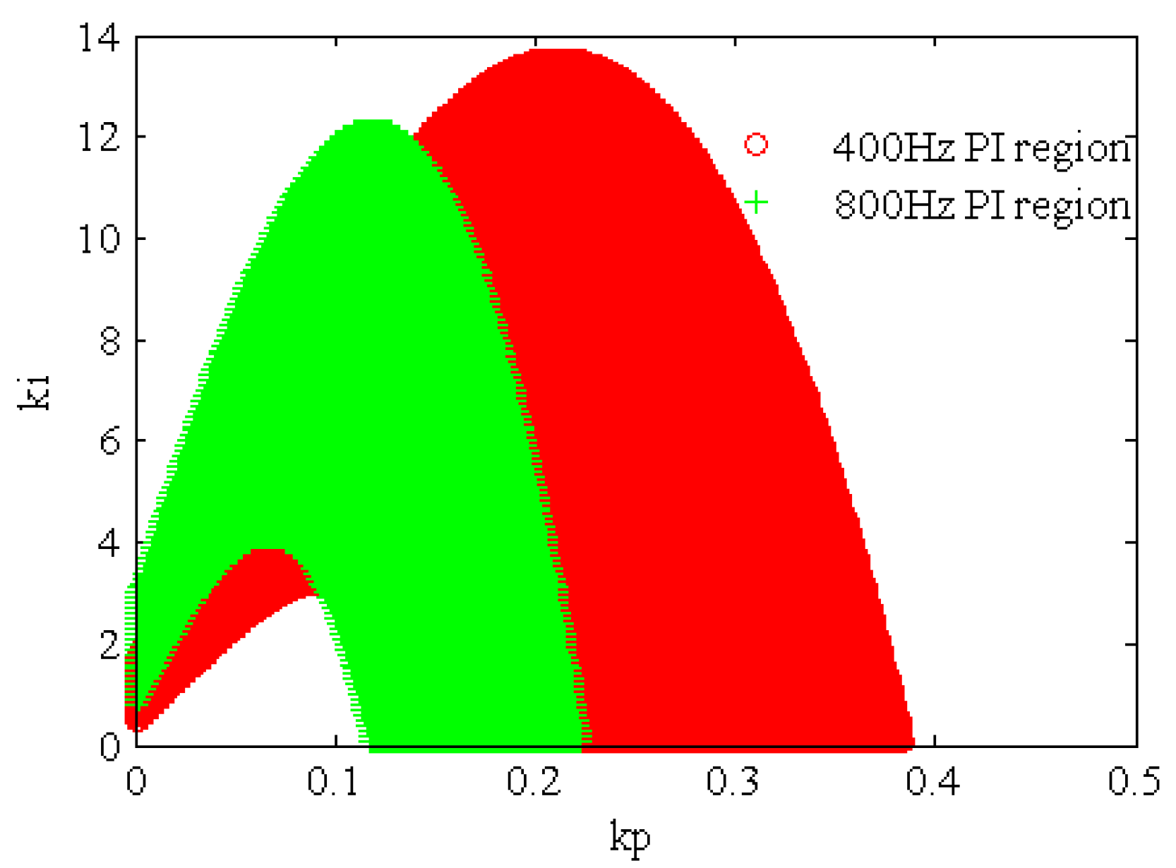
- ➢
- Controller parameter under 400 Hz and 800 Hz is feasible in different regions for the same stability requirements;
- ➢
- For kp ki feasible region under the same stability demand, domain area under 400 Hz is greater than that under 800 Hz. This is because the stability of the system descends if frequency increases, so the kp ki parameter tuning requirements are more stringent, thus its feasible region is smaller;
- ➢
- Feasible regions have overlapping parts. If we use the same PI parameter at different frequencies, the PI parameter is required to fall on the overlapping part of the feasible region.
5. Software Algorithm Design
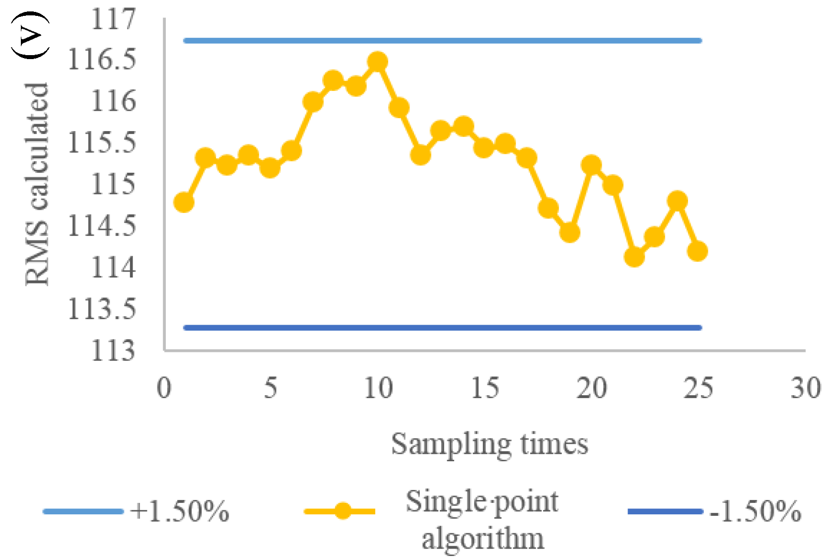
5.1. RMS Algorithm
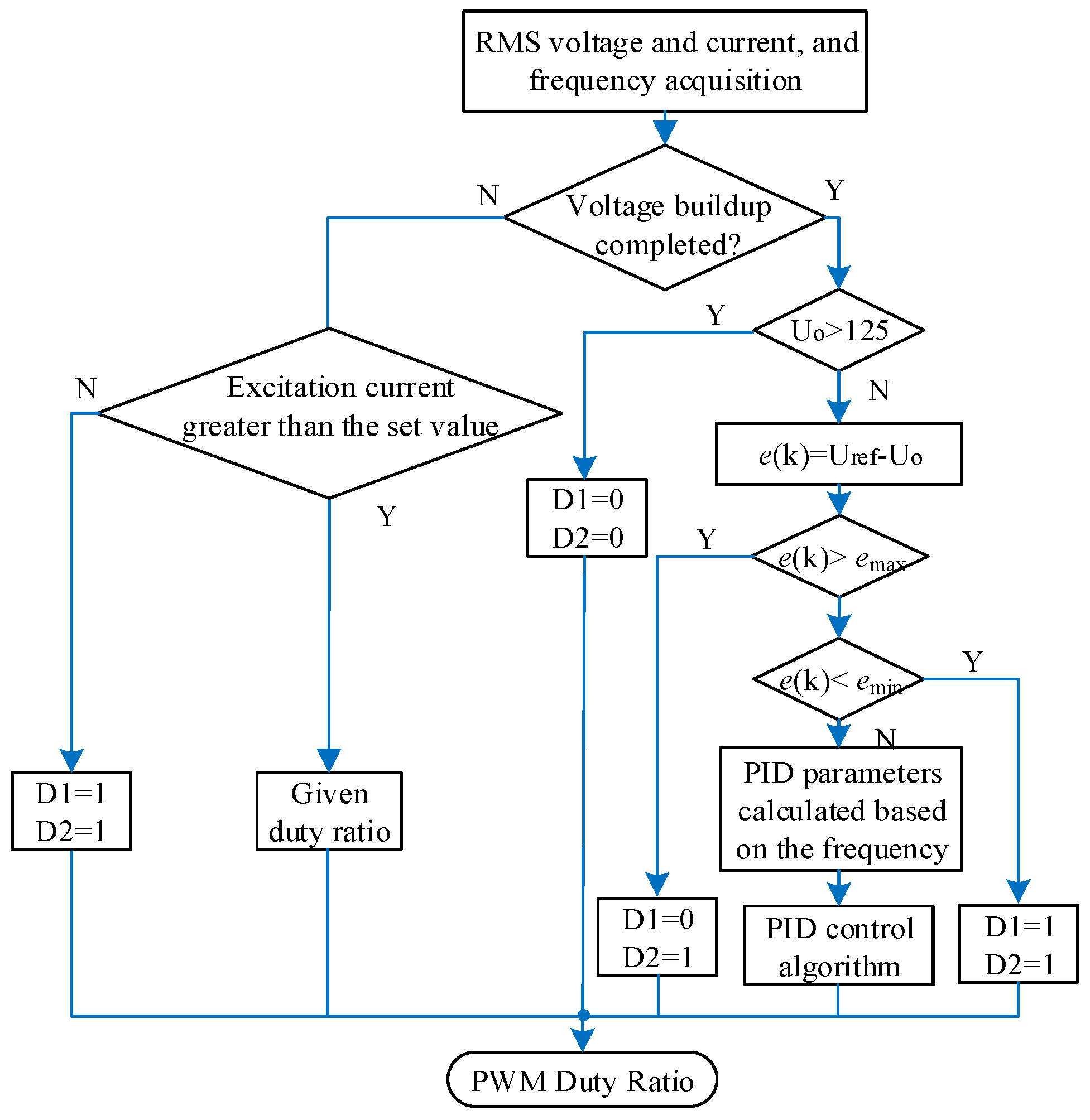
5.2. Voltage Regulation Algorithm
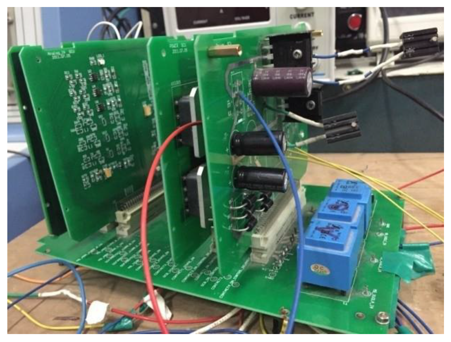
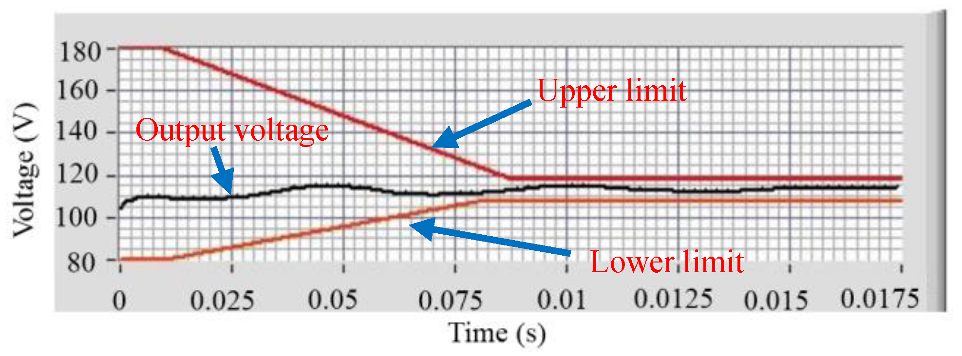
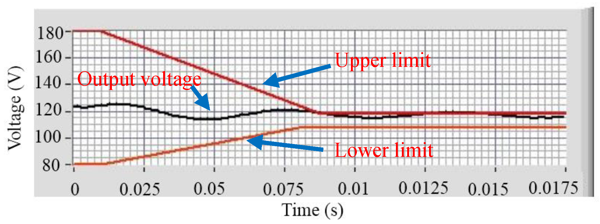
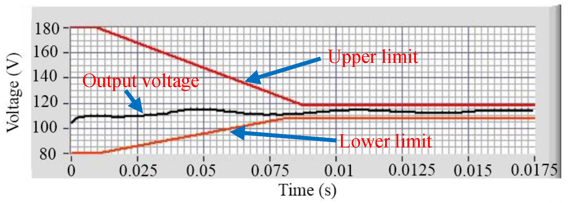
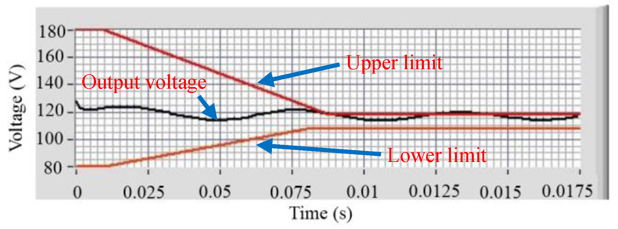
6. Experimental Verification
7. Conclusions
Acknowledgments
Author Contributions
Conflicts of Interest
Nomenclature
| Generator stator d, q, and 0 currents | |
| Generator stator d, q, and 0 voltages | |
| Generator stator d, q and 0 flux linkages | |
| Generator damper windings d and q currents | |
| Generator damper windings d and q flux linkages | |
| Generator field winding current, voltage and flux linkage | |
| Generator field winding current and voltage | |
| Field winding resistance and inductance | |
| Generator stator and damper winding resistance | |
| Generator d and q magnetizing inductances | |
| Synchronous inductance in dq0 coordinates | |
| Damper winding synchronous inductance | |
| Load inductance and resistance | |
| Generator rotating speed |
Appendix A
Appendix B

| Parameters | Values |
|---|---|
| P | 30 KVA |
| n | 2 |
| V | 115 V |
| f | 400 Hz |
| PF | 0.75 |
| Ra | 0.0364 Ω |
| Rf | 1.9 Ω |
| Rd | 0.0445 Ω |
| Rq | 0.1414 Ω |
| Ld | 8.0360 × 10⁻⁴ H |
| Lq | 2.8792 × 10⁻⁴ H |
| Lls | 4.1690 × 10⁻⁵ H |
| L0 | 3.0081 × 10⁻⁷ H |
| Lf | 0.1615 Ω |
| LDD | 7.7977 × 10⁻⁴ H |
| LQQ | 2.5017 × 10⁻⁴ H |
| Maf | 0.0090 H |
| Md | 6.2210 × 10⁻⁴ H |
| Mq | 2.0105 × 10⁻⁴ H |
| Mdf | 0.0110 H |
References
- Alnajjar, M.; Gerling, D. Predictive control of variable frequency brushless excited synchronous generator for more electric aircraft power system. In Proceedings of the 2014 International Conference on Electrical Machines (ICEM), Berlin, Germany, 2–5 September 2014; pp. 2127–2132. [Google Scholar]
- Li, W.; Liu, W.; Wu, W.; Zhang, X.; Gao, Z.; Wu, X. Fault diagnosis of star-connected auto-transformer based 24-pulse rectifier. Measurement 2016, 91, 360–370. [Google Scholar] [CrossRef]
- Shi, M.; Zhou, B.; Wei, J.; Zhang, Z.; Mao, Y.; Han, C. Design and practical implementation of a novel variable-speed generation system. IEEE Trans. Ind. Electron. 2011, 58, 5032–5040. [Google Scholar] [CrossRef]
- Li, W.; Liu, W.; Zhang, X.; Gao, Z.; Xie, M.; Wang, H. Study on impedance characteristics of aircraft cables. Int. J. Aerosp. Eng. 2016, 2016, 645–650. [Google Scholar] [CrossRef]
- European Committee for Standardization. Characteristics of Aircraft Electrical Systems; European Standard EN 2282; European Committee for Standardization: Brussels, Belgium, 1992. [Google Scholar]
- Xavier, R. New trends and challenges of electrical networks embedded “in more electrical aircraft”. In Proceedings of the IEEE ISIE (International Symposium on Industrial Electronics) Conference, Toulouse, France, 27–30 June 2011; pp. 26–31. [Google Scholar]
- Yu, L.; Zhang, Z.; Chen, Z.; Yan, Y. Analysis and verification of the doubly salient brushless DC generator for automobile auxiliary power unit application. IEEE Trans. Ind. Electron. 2014, 61, 6655–6663. [Google Scholar] [CrossRef]
- Saidy, M.; Hughes, F. Predictive excitation control of a turboalternator. Int. J. Control 1995, 61, 507–524. [Google Scholar] [CrossRef]
- Chen, H.C.; Huang, M.S.; Liaw, C.M.; Chang, Y.C.; Yu, P.Y.; Huang, J.M. Robust current control for brushless DC motors. IEE Proc.-Electr. Power Appl. 2000, 147, 503–511. [Google Scholar] [CrossRef]
- Ma, X. Digital Generator Control Unit for Synchronous Brushless Generator; Virginia Polytechnic Institute and State University: Blacksbug, VA, USA, 2004. [Google Scholar]
- Morshed, M.J.; Fekih, A. A new fault ride-through control for DFIG-based wind energy systems. Electr. Power Syst. Res. 2017, 146, 258–269. [Google Scholar] [CrossRef]
- Morshed, M.J.; Fekih, A. A fault-tolerant control paradigm for microgrid-connected wind energy systems. IEEE Syst. J. 2016, PP, 1–13. [Google Scholar] [CrossRef]
- Khodabakhshian, A.; Morshed, M.J.; Parastegari, M. Coordinated design of STATCOM and excitation system controllers for multi-machine power systems using zero dynamics method. Int. J. Electr. Power Energy Syst. 2013, 49, 269–279. [Google Scholar] [CrossRef]
- Li, W.; Zhang, X.; Li, H. Design of star-connected autotransformer based 24-pulse rectifier and its application in the more electric aircraft. Eur. Power Electron. Drives J. 2014, 24, 37–44. [Google Scholar]
- Li, W.; Li, H.; Ni, F.; Zhang, X.; Monti, A. Digital automatic voltage regulator for synchronous generator considering sensor failure. Eur. Trans. Electr. Power 2012, 22, 1037–1052. [Google Scholar] [CrossRef]
- Krause, P.C.; Wasynczuk, O.; Sudhoff, S. Analysis of Electric Machinery and Drive Systems, 2nd ed.; IEEE-Press/Wiley Interscience: Piscataway, NJ, USA, 2002. [Google Scholar]
- Jadric, I.; Borojevic, D.; Jadric, M. Modeling and control of a synchronous generator with an active DC load. IEEE Trans. Power Electron. 2000, 15, 303–311. [Google Scholar] [CrossRef]
- Zeng, X.J.; Yu, K.; Wang, Y.Y.; Xu, Y. A novel single phase grounding fault protection scheme without threshold setting for neutral ineffectively earthed power systems. CSEE J. Power Energy Syst. 2016, 2, 73–81. [Google Scholar] [CrossRef]
- Li, W.; Liu, W.; Liu, S.; Ji, R.; Zhang, X. Impedance characteristics study of three-phase aircraft power wires. Measurement 2015, 78, 235–244. [Google Scholar] [CrossRef]
- Li, Y.; Liu, Q.; Hu, S.; Liu, F.; Cao, Y.; Luo, L.; Rehtanz, C. A virtual impedance comprehensive control strategy for the controllably inductive power filtering system. IEEE Trans. Power Electron. 2017, 32, 920–926. [Google Scholar] [CrossRef]
- Li, W.; Liang, L.; Liu, W.; Wu, X. State of charge estimation of lithium ion batteries using a discrete time nonlinear observer. IEEE Trans. Ind. Electron. 2017, 64, 8557–8565. [Google Scholar] [CrossRef]


| Frequency (Hz) | Magnitude Margin (dB) | Phase Margin (deg) |
|---|---|---|
| 400 Hz | 3.37 | 12.4 |
| 500 Hz | 1.03 | 3.81 |
| 600 Hz | −0.63 | −2.3 |
| 700 Hz | −1.89 | −7.39 |
| 800 Hz | −2.9 | −11.6 |
| Speed (r/min) | Steady State Value (V) | ||
|---|---|---|---|
| Phase A | Phase B | Phase C | |
| 6500 | 115.4 | 115.3 | 115.3 |
| 6900 | 115.2 | 115.1 | 115.1 |
| 7300 | 115.1 | 115.1 | 115.1 |
| 7600 | 115.3 | 115.3 | 115.3 |
| 8000 | 115.2 | 115.2 | 115.2 |
| 8200 | 115.2 | 115.2 | 115.2 |
| 8400 | 115.1 | 115.1 | 115.1 |
| Speed (r/min) | Steady-State Output Voltage (V) | Voltage Modulation (V) | |
|---|---|---|---|
| 8000 | 115.22 | 2.12 | 4.034 (modified) |
| 8000 | 116 | 5 | 5 (before) |
| Speed (r/min) | With Rated Load | ||
|---|---|---|---|
| Steady-State (V) | Voltage Modulation (V) | ||
| 6500 | 115.46 | 2.43 | 5 |
| 7400 | 115.44 | 1.68 | 4.45 |
| 7800 | 115.06 | 1.91 | 4.28 |
| 8000 | 115.08 | 2.51 | 4.03 |
| 8200 | 115.15 | 2.34 | 3.82 |
© 2018 by the authors. Licensee MDPI, Basel, Switzerland. This article is an open access article distributed under the terms and conditions of the Creative Commons Attribution (CC BY) license (http://creativecommons.org/licenses/by/4.0/).
Share and Cite
Li, W.; Yang, Y.; Zhang, X. Digital Generator Control Unit Design for a Variable Frequency Synchronous Generator in MEA. Energies 2018, 11, 96. https://doi.org/10.3390/en11010096
Li W, Yang Y, Zhang X. Digital Generator Control Unit Design for a Variable Frequency Synchronous Generator in MEA. Energies. 2018; 11(1):96. https://doi.org/10.3390/en11010096
Chicago/Turabian StyleLi, Weilin, Yang Yang, and Xiaobin Zhang. 2018. "Digital Generator Control Unit Design for a Variable Frequency Synchronous Generator in MEA" Energies 11, no. 1: 96. https://doi.org/10.3390/en11010096
APA StyleLi, W., Yang, Y., & Zhang, X. (2018). Digital Generator Control Unit Design for a Variable Frequency Synchronous Generator in MEA. Energies, 11(1), 96. https://doi.org/10.3390/en11010096