Article

Study of an Altered Magnetic Circuit of a Permanent Magnet Linear Generator for Wave Power

1
Department of Engineering Sciences, Uppsala University, Box 534, 751 21 Uppsala, Sweden
2
Seabased Industry AB, Verkstadsgatan 4, 453 30 Lysekil, Sweden
3
Department of Electrical Engineering, Chalmers University of Technology, 412 96 Gothenburg, Sweden
*
Author to whom correspondence should be addressed.
Energies 2018, 11(1), 84; https://doi.org/10.3390/en11010084
Submission received: 15 November 2017 / Revised: 23 December 2017 / Accepted: 26 December 2017 / Published: 31 December 2017
(This article belongs to the Special Issue Electric Machines and Drives for Renewable Energy Harvesting 2017)

Abstract

:
The wave energy converter (WEC) studied and developed at Uppsala University in Sweden is a point absorbing buoy connected to a linear generator (LG) on the seabed. Previous studies have improved the sustainability of the generator, changing its magnets from Nd2Fe14B-magnets to ferrites. In this paper, the magnetic circuit of the linear generator is further studied. Ferrite magnets of two different types (Y30 and Y40) are studied along with different shapes of pole shoes for the system. The finite element method (FEM) simulations in a program called Ace are performed. The results show that a linear generator including both Y30 and Y40 magnets and shortened T-shaped pole shoes can generate a similar magnetic energy in the airgap as a linear generator only containing Y40 magnets and rectangular pole shoes. This shows that the magnetic circuit can be altered, opening up sizes and strengths of magnets for different retailers, and thereby possibly lowering magnet cost and transportation. This work was previously presented as a conference at the European Wave and Tidal Energy Conference (EWTEC) 2017 in Cork, Ireland; this manuscript has been carefully revised and some discussions, on magnet costs for example, have been added to this paper.

1. Introduction

Energy contained in ocean waves is considered a promising source of renewable energy by many countries. Although the first patent on the wave energy conversion technique was obtained more than 100 years ago [1], different research groups all over the world are still striving to develop an efficient and economically viable means of converting wave energy to electrical energy [2]. A diverse variety of wave energy converters (WECs) can be classified based on their location, type of absorption, and power take-off [1,3,4].
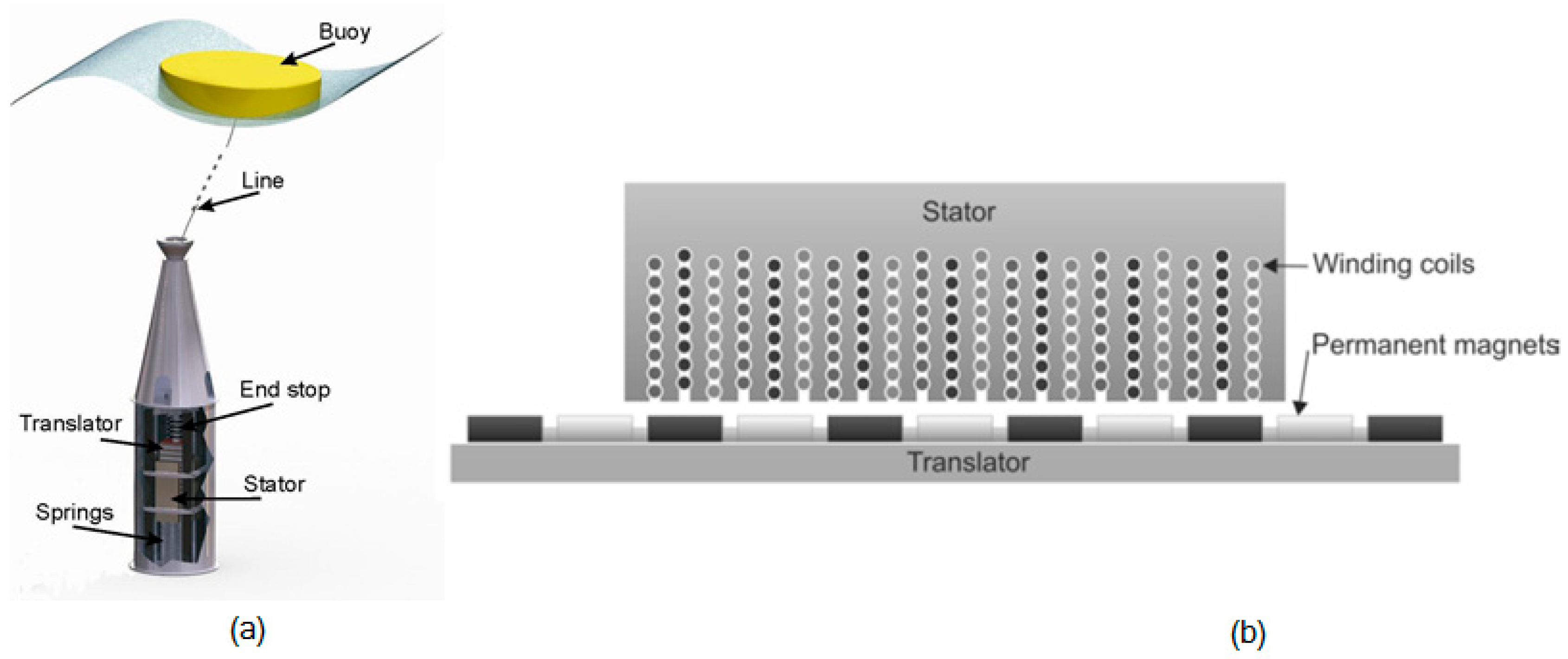
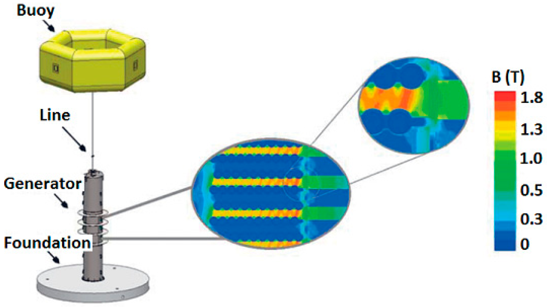
The WEC concept developed at Uppsala University in Sweden, illustrated in Figure 1a, is an offshore device of a point absorption type with a permanent magnet linear generator (PMLG) power take-off. The PMLG is directly driven and placed on the seabed, and protected from seawater by a watertight hull. The linear generator (LG) contains a stator and a translator with magnets [5], as shown in Figure 1b. A voltage is induced in the stator coils due to the relative translator motion. The operational principle is rather simple, ensuring the WEC’s robustness, low cost, and sustainability. Seabased Industry AB (Lysekil, Sweden, http://www.seabased.com/en/) is currently commercializing a similar WEC with previous projects in Scandinavia and Ghana [6]. 
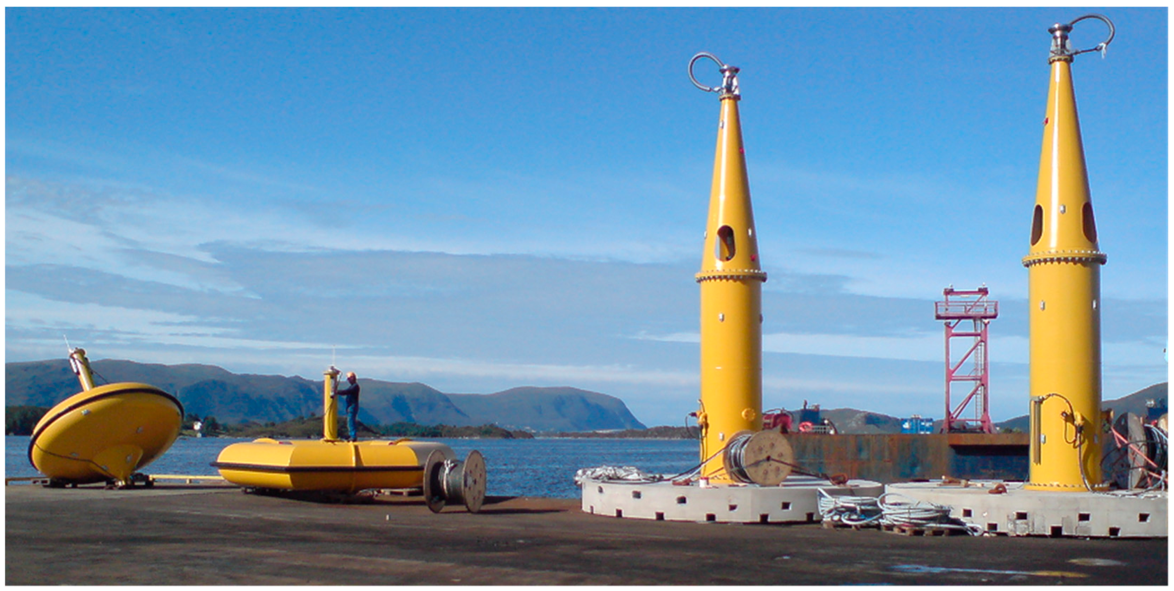
Figure 2 shows a photo of buoys and translators on the harbor before offshore deployment in Norway.
Since 2006, the WEC system developed at Uppsala University has undergone several offshore experiments at the research site in Lysekil, Sweden [7,8,9,10,11], covering different aspects on wave energy conversion including the environmental aspects [12,13], wave power park layout analysis [14], manufacturing [15,16] and deployment [6] processes, WEC survivability in extreme seas [17], and efficiency of WECs subjected to tides [18].
An application of a direct drive PMLG for wave energy conversion (mainly used for the Archimedes Wave Swings) was suggested in [19]. PMLGs for single-body point absorbers were discussed in [20,21] and for two-body floating point absorbers in [22]. Various topologies for PMLG for wave power conversion were summarized in [23], and some generator designs were compared in [23,24,25,26]. The type of magnets in the LG affects the performance and sustainability of the WEC. A sketch of the magnetic field of the Uppsala WEC is shown in Figure 3 [27]. Nd2Fe14B-magnets can be used in the LG. Issues regarding environment, health, and price [28] do however make these rare earth magnets unfit for a sustainable WEC. Ferrite permanent magnets (PMs), with magnetization in the direction of motion, are placed between pole shoes and used in the LG. This setup is proving to be a sustainable alternative to Nd2Fe14B [27,29].
The aim of this paper is to discuss an altered magnetic circuit of a PMLG for wave energy conversion. The magnetic energy in the airgap between the stator and translator is determined, using the finite element method (FEM) simulations, as parts of the magnetic material and the pole shoes are altered from the previous design, where only one type of ferrite and rectangular pole shoes was included. There are several reasons as to why it would be interesting to further study different magnetic circuit designs of the LG: the stronger Y40 magnets [30] are generally more expensive than Y30 and are not available from all manufacturers; increasing the flexibility of the magnetic circuit may open up the possibility of using cheaper PMs, shorter material transportations, in-house magnet production and so on; and the different designs of pole shoes can decrease magnetic leakage flux in the LG, resulting in a higher magnetic energy in its airgap, possibly increasing the performance of the LG. The following study was previously included as a conference [31] and the manuscript has been revised and partly rewritten with additional discussions, for example, on magnet costs.
Previous studies have suggested that a mixed magnet grade design can be used for electrical machines [32,33,34,35,36,37,38,39]. Several of these studies have discussed magnetic circuits with rare earth magnets [34,35,36,38,39], whereas others included ferrites [32,33] or a mixture of ferrites and rare earth metals [37]. Most reviewed research on mixed magnet grade involved rotating machines [32,33,34,35,37,38,39]; however, a linear PM motor was studied in [36]. The focus of these publications were generally of the torque- or total harmonic distortion (THD) measurements of the system [36,37,38,39] or its demagnetization behavior [32,33,34,35]. A number of studies have investigated linear machines with magnetization in the direction of motion [40,41,42,43,44]. Furthermore, modified pole shoes for a rotating PM synchronous wind turbine [45] and different salient pole shoe faces for a synchronous machine [46] were previously studied. However, none of the reviewed literature has looked into the influence of replacing a fraction of the pole shoe with a non-magnetic material closest to the shaft or using mixed magnet grading for the studied WEC system.

2. Theory and Method

The theoretical background of this study is based on Maxwell’s equations. The PMs (here divided magnets) are modelled by a current sheet approach, as described in [47]. A magnetic vector potential, A, is used in Maxwell’s equations and the contribution from displacement currents is neglected. As described in [48], the time-dependent induced eddy currents are removed for a steady state simulation, resulting in:
× ( 1 μ r μ 0 × A ) = J s + J p m ,
where the source current density J s represents the current densities of the stator windings and J p m represents the permanent magnets as an equivalent current density [49].
In this study, an in-house developed program Ace (developed at ABB AB, Coporate Research, Västerås, Sweden) was used to model the magnetic circuit of the LG [50]. The software solves Maxwell’s equations for a two-dimensional segment of a generator using FEM, approximating a constant field in the axis of the conductor windings and simulating each magnet as a closed current loop. Several previous studies have used this simulation tool and the results were verified with experimental data in [51,52]. Simulations in Ace on a segment of the LG were previously presented in [53,54] and the longitudinal end effects of the LG were studied more thoroughly in [
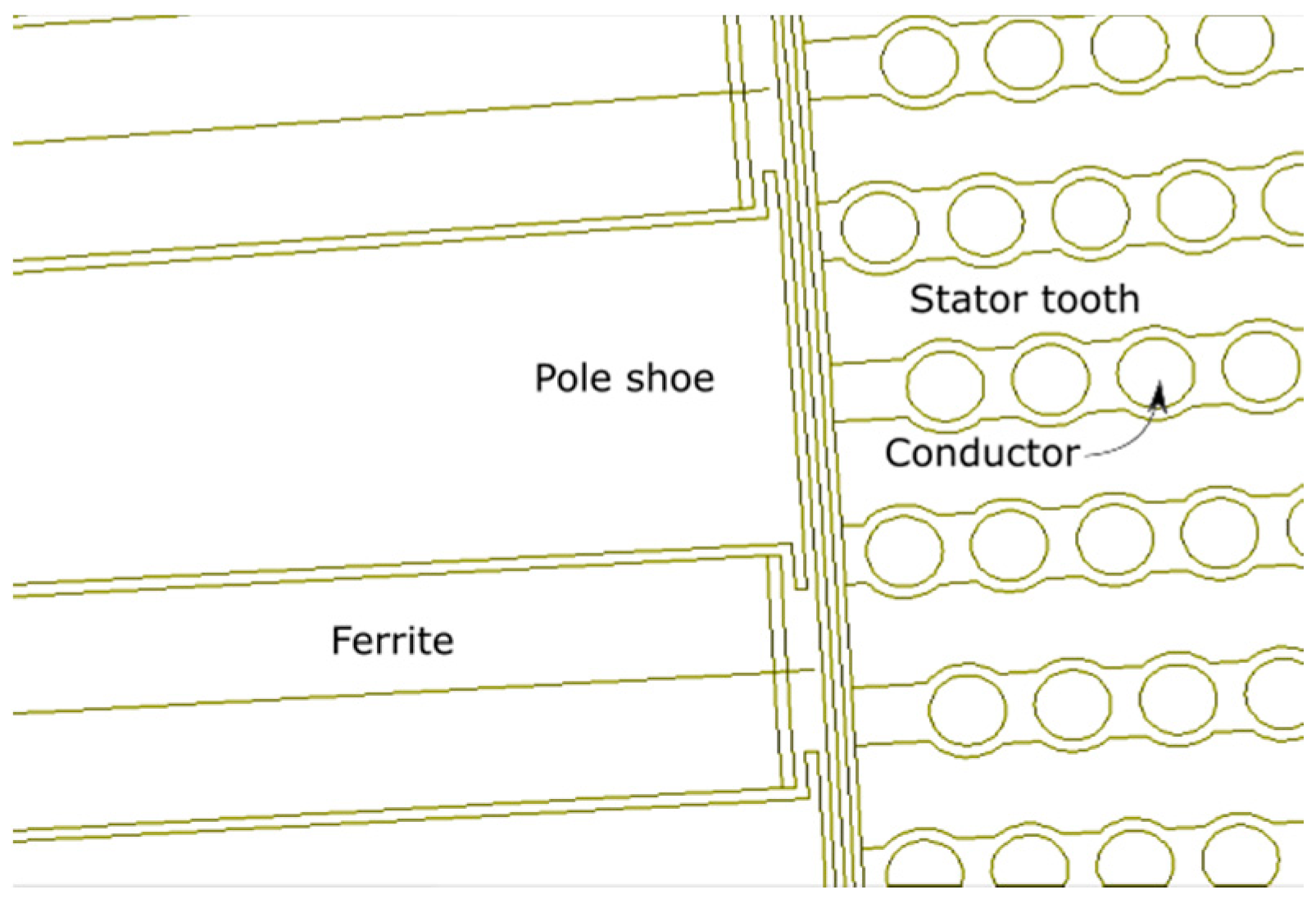
55]. These effects are neglected here. A segment of the studied WEC LG is shown in Figure 4, illustrating the translator, with ferrite PMs and T-shaped pole shoes, next to the stator, with coils and stator steel. This geometry is used in Ace.
The properties of magnets used in the modelling are inserted into the software. Here, the ferrite PMs of type Y30 and Y40 are investigated. In Table 1, some important properties of Y30 and Y40 are shown [30]. Y40 is a stronger ferrite PM than Y30. The relative permeability of Y30 and Y40 were calculated using the mean values of the remanence and the energy product. All values are presented in Table 1.
The cost of ferrites varies with the chosen retailer, the size and geometry of the magnet, the number of magnets bought at the same time and so on, according to contacted retailers with delivery to Sweden (Bakker Magnetics, (Eindhoven, The Netherlands) www.bakkermagnetics.com/en; Compotech, (Stockholm, Sweden) www.en.compotech.se/; BJA Magnetics (Leominster, MA, USA) www.bjamagnetics.com/). It is indicated that the price of Y40 is several times higher than Y30 for this large size. In the following analysis, we have used the ratio 6:1 when comparing the prices of Y40 to Y30. The cost of Y40 is higher than Y30 because of the increased magnetic properties and the more advanced manufacturing processes involved when producing larger magnets of higher grading. The relative cost difference between Y30 and Y40 increases with magnet size. The prices of the magnets generally increase with the strength of the magnets. Moreover, the delivery (shipping) time, capacity and the cost of other necessary tools for processing may affect the overall price and choice of suitable retailer.
The method of this study is to perform simulations in Ace for a section of the LG with a stepwise altered magnetic circuit, partly changing the ferrites from Y40 to Y30, while altering the shape of the pole shoes to increase the magnetic energy in the airgap. The study is restricted to include only two types of ferrites (Y30 and Y40) and two types of pole shoes (rectangular and T-shaped). The simulations in Ace are subdivided into three studies, as described in more detail, namely investigations of mixed ferrite permanent magnets, different designs of pole shoes and the combination of mixed magnets and different pole shoes. The results from all studies are analyzed and some conclusions are drawn.

2.1. Mixed Ferrite Permanent Magnets

The magnetic material in the LG is changed from 100% of Y40 to 100% of Y30 in several steps, where some cases include both Y40 and Y30, as described in Table 2. The total length of the magnetic material is 120 mm and the width is 20 mm. The pole shoes are rectangular with a length of 124 mm and width 15 mm.

2.2. Different Designs of Pole Shoes

The second study is restricted to two different shapes of pole shoes, namely rectangular and T-shaped, as described in Table 3 and shown in Figure 4. The magnets are of type Y40. The T-shaped pole, with more material in the proximity of the stator, may increase the portion of magnetic flux through the airgap and stator.

2.3. Mixed Magnets and Different Pole Shoes

Some combinations of the Y30 and Y40 magnets are investigated together with T-shaped pole shoes of different length, as described in Table 4.

3. Results

The results from the three studies (mixed ferrite permanent magnets, different designs of pole shoes and mixed magnets and different pole shoes) are presented in the following section, including the magnetic energy per unit stack length (Ws/m) summed up in the airgap and figures showing the magnetic field lines in the LG segment for the different cases described above.

3.1. Results for Mixed Ferrite Permanent Magnets

The total magnetic energy in the airgap and the relative cost and relative magnetic energy cost for each case can be seen in Table 5. The relative cost is based on the prices for a large magnet, of full size suitable for the WEC. The relative magnetic cost is calculated as the relative cost divided by the magnetic energy in the airgap, and normalizing the result in regards to Y30. Case 1, only including Y40 magnets, resulted in the highest magnetic energy in the airgap. Case 2b, with 25% Y30 and 75% Y40, generates the second highest magnetic energy in the airgap; this simulation is shown in Figure 5. Placing Y40 closer to the stator than Y30 results in a slightly higher magnetic energy in the airgap. The magnetic energy in the airgap per unit stack length (Ws/m) for different amounts of Y40 (%) and Y30 is shown in Figure 6. Note that a magnet of type Y40 costs about six times more than a magnet of type Y30, see Table 5.

3.2. Results for Different Designs of Pole Shoes

The results for the studies with different pole shoes are shown in Table 6. The slightly higher magnetic energy in the airgap was obtained with the T-shaped pole shoe, showing that the change of pole shoe face can increase the magnetic flux through the airgap and in the stator.

3.3. Results for Mixed Magnets and Different Pole Shoes

Table 7 shows the magnetic energy in the airgap for mixed magnets and different pole shoes. Case 9, which used 25% Y30, 75% Y40 and a T-shaped pole shoe shortened to 85% of its initial length, resulted in the highest magnetic energy in the airgap. Shorter T-shaped pole shoes lead to a higher magnetic energy in the airgap than the 124-mm long T-shaped pole shoe. Cases 7 and 8 are shown in Figure 7 and Figure 8, respectively.
In Figure 9, the magnetic energy per unit stack length is plotted against a length of the increasing pole shoes for the combination of 2b and T, showing that there is a maximum magnetic energy in the airgap for a slightly shorter pole shoe, namely about 85% of its maximum length.

4. Discussion

Offshore marine renewable energy, such as wave power and marine current power, has slowly become more cost-efficient and reliable. Marine renewable energy has been considered an alternative energy source for countries with a coastline, possibly challenging the more established renewable energy sources, such as solar or wind power. Moreover, several parts of the world realize the possibility of powering small communities or certain services (such as desalination plants [56]) with renewable energy. Increasing the number of intermittent energy sources naturally imposes many engineering challenges and in order to improve the wave energy systems, which is discussed in this paper, careful consideration of the entire process from wave-to-wire should be undertaken. In this light, the LG of the WEC designed in Sweden continues to benefit from research concerning the (economic, environmental, and social) sustainability of the system. This research approaches the sustainability of one of its features, namely the sustainability of the LG, and specifically its magnetic circuit.
There is a price difference between the stronger and more expensive Y40 and the less strong magnet Y30, as noted in Section 2. The prices of ferrites are today strongly dependent on magnet sizes, grades and purchased quantities. The price of regular (large) sized ferrites, suitable for this type of WEC, with certified quality Y40 is about six times more expensive than an Y30 of same size, geometry and quantity, according to current retailers. Meanwhile, much smaller ferrite magnets of type Y40 are seemingly more in the same price range as Y30 magnets (where Y30 is about 30% cheaper according to retailers). The relative price difference between magnets of type Y30 and Y40 will go from 1:6, for large magnets, towards more similar values for smaller sizes. However, all results still indicate that it is more affordable with Y30 magnets than Y40 and that Y40 should be put closest to the airgap, if both Y30 and Y40 are included in the magnetic circuit. As the magnet prices are size dependent, it may be interesting to change one large magnet into several smaller magnets, if the generator design enables their mounting. The more advanced instruments needed for producing larger magnets of higher grading influences the costs, and not all manufacturers provide ferrites of Y40 quality. That is, the overall supply and demand affects the ferrite prices. This further suggests that it is interesting to look into the possibility of varying the magnetic circuit of a PM generator, or varying the shapes and sizes of the magnets to optimize the overall price and to ensure a reliable magnet cost. From an industrial point of view, the development of a flexible magnetic circuit (possibly produced with different types of magnets and pole shoes) can reduce the overall WEC cost in several ways, for example, by increasing the power output of the WEC, and taking the opportunity to more freely choose which company to produce the magnets and the requirements of the magnets in terms of quantity, quality, geometry, transportation, ethical working situation and so on. Moreover, it may be possible to produce some magnets in-house. In the future, an LG with mixed types of ferrite permanent magnets might be constructed and studied experimentally.
The power output from a WEC LG generally increases with increasing magnetic energy in the stator/translator airgap (unless the stator steel gets saturated or the WEC is undersized in some way). However, how much the variations of magnetic energy in the airgap affect the voltage induced in the WEC coil windings and the power output of the WEC have not been fully studied here. That is, there are still questions on whether this type of (more complicated) circuit design is justifiable from the cost perspective. Moreover, the dimensions of the suggested T-shaped pole shoes, described in Table 3, are so small that the suggested pole shoe design may only be possible and interesting to study in simulations at this stage.
When altering the magnetic circuit of an LG to obtain a higher sustainability, a similar or increased magnetic performance compared to other circuit designs is desirable. Comparing the resulting values for an LG with rectangular pole shoes and only Y40 magnets, as presented in Table 5, Case 1 (123 Ws/m), with the values for a mixed Y30 and Y40 LG with T-shaped pole shoes (see Table 7), the performance in terms of magnetic energy in the stator/translator airgap was similar although the magnetic circuit was redesigned.
As can be seen in Figure 6, there is an approximately linear relation between the magnetic energy per unit stack length in the airgap and the amount of Y40 in the linear generator. As the stronger magnetic material (Y40) is placed further away from the stator steel, the leakage flux, which does not reach the airgap, increases, resulting in a lower magnetic energy in the airgap than for those cases where the stronger magnetic material is placed closer to the stator. Figure 6 also indicates that the current sheet approach for modelling the magnets may cause small additional magnetic flux paths for the divided magnets, when simulating this system. Naturally, all resulting figures and values presented in the results are limited in accuracy and resolution by the features of the simulation tool.
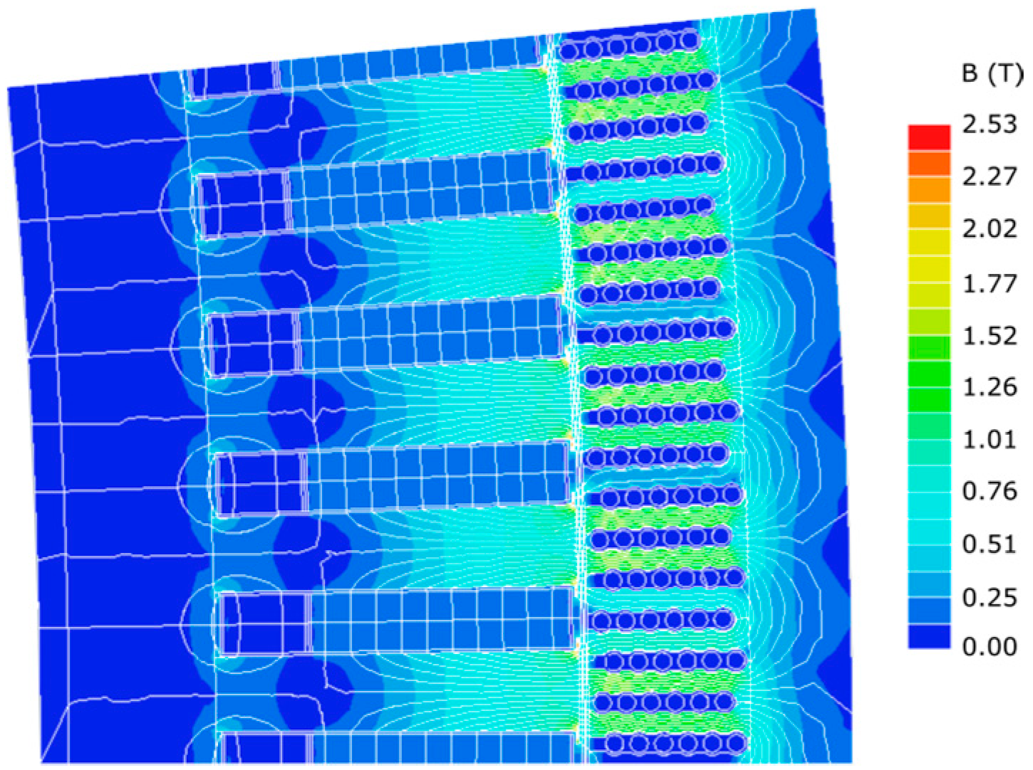
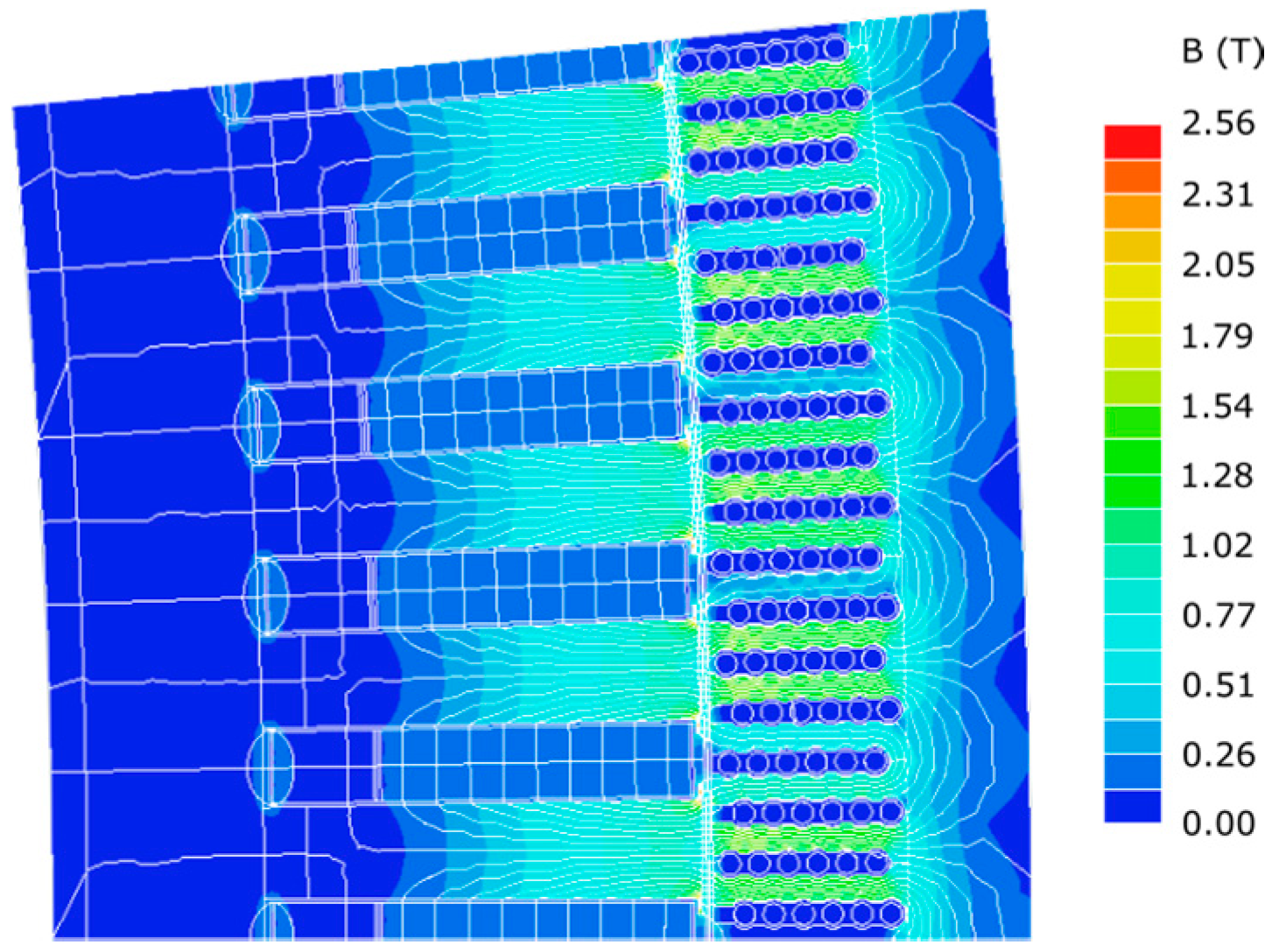
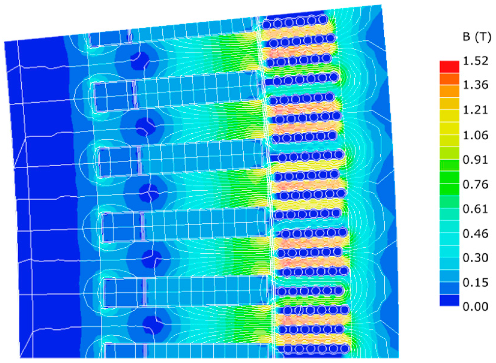
The current study found that it is possible to increase the magnetic energy in the airgap by altering the design of the pole shoes: making them shorter and changing their shapes from a rectangular shape to a T-shape. The shape is changed in order to decrease the leakage flux in the LG. By examining Figure 5, a magnetic flux leakage from the left part of the magnet, not reaching the stator, can be identified. In order to increase the magnetic energy in the airgap between the stator and translator, a shorter pole shoe was a successful choice, redirecting the previous magnetic leakage flux towards the stator. A T-shaped pole shoe also increased the magnetic energy in the airgap slightly compared to a regular rectangular pole shoe. However, due to the more advanced geometry of the pole shoe, the change in shape from a rectangular to a T-shaped pole shoe may not be the best choice from an industrial point of view. The shorter pole shoes (of a rectangular shape) are seemingly easier to manufacture than the full-length T-shaped pole shoe.

5. Conclusions

In this paper, the magnetic circuit of an LG, for a direct-driven wave power system, was studied using FEM simulations with the software Ace. The results provided estimations of the magnetic energy in the airgap between the stator and translator (Ws/m), as the magnetic properties of the LG were changed in different design steps. The study presents an alternative design of an LG with different ferrite PMs (of the type Y30 and Y40) and pole shoes (rectangular and T-shaped). Changing parts of the magnetic material from Y40 to Y30 leads to a decrease in the resulting airgap magnetic energy. On the other hand, the magnetic energy in the airgap increased as the ferrite of type Y40 was placed closer to the stator steel than Y30 (for mixed magnets), as this lowers the magnetic leakage flux in the circuit. The cost of the ferrites with high grading (i.e., Y40) is increasing with block size, due to a more advanced manufacturing process for larger magnets of high grading. The possibility to reduce costs with the use of smaller magnets is a strong argument to why this kind of investigation for magnetic circuits of electrical machines for industrial purposes can be interesting to continue with in the future.
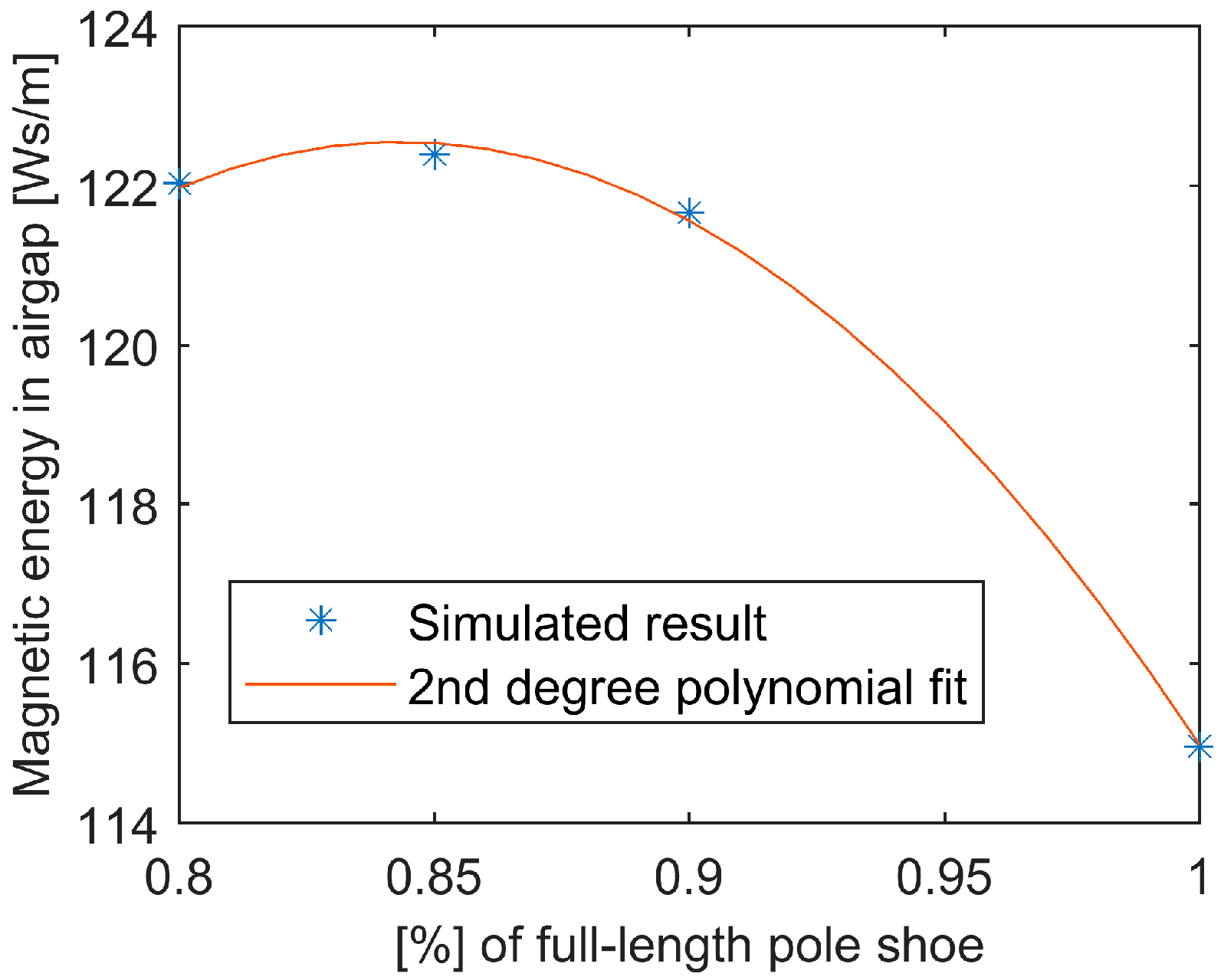
It can be concluded that a shortened pole shoe increases the magnetic energy in the airgap, since it decreases the leakage flux and thereby redirects the flux towards the airgap. For the studied case, the optimal pole shoe length was found to be 85% of its original length. This study has identified that the pole shoe design will change the features of the LG magnetic circuit. In industry, there will be a trade-off between ferrite and pole shoe costs. More research is needed in order to establish if it will be interesting, from a sustainability perspective, to create an LG using mixed types of ferrites and pole shoe designs.

Acknowledgments

This research was financially supported by the Swedish Research Council, VR grant No. 2015-03126, the Swedish Energy Agency P42243-1 and Uppsala University. This work was conducted within the STandUP for Energy strategic research framework. We would like to express our gratitude towards Arne Wolfbrandt and Urban Lundin for their support and development of the Ace tool, as well as acknowledge ABB.

Author Contributions

This was a collaborative work. B.E. and M.L conceived and designed the experiments. J.S. and J.L. performed the simulations with guidance from mainly S.E., C.B. and B.E. All authors analyzed the results and contributed to the discussion. All authors contributed to the writing of the paper, J.L. wrote most of the paper and I.T. and J.S. contributed significantly to the text.

Conflicts of Interest

The authors declare no conflict of interest. The founding sponsors had no role in the design of the study; in the collection, analyses, or interpretation of data; in the writing of the manuscript, and in the decision to publish the results.

Nomenclature

AVs/mMagnetic vector potential
BrTRemanence
HcA/mCoercivity
HciA/mIntrinsic coercivity
JsA/m2Source current density
JpmA/m2Permanent magnet current density
μ r N/A2Relative permeability
μ 0 N/A2Permeability of free space
FEM Finite element method
LG Linear generator
PM Permanent magnet
PMLG Permanent magnet linear generator
THD Total harmonic distortion
WEC Wave energy converter

References

  1. De Falcão, A.F.O. Wave energy utilization: A review of the technologies. Renew. Sustain. Energy Rev. 2010, 14, 899–918. [Google Scholar] [CrossRef]
  2. Falnes, J. A review of wave-energy extraction. Mar. Struct. 2007, 20, 185–201. [Google Scholar] [CrossRef]
  3. Falnes, J.; Lovseth, J. Ocean wave energy. Energy Policy 1991, 19, 768–775. [Google Scholar] [CrossRef]
  4. Drew, B.; Plummer, A.R.; Sahinkaya, M.N. A review of wave energy converter technology. Proc. Inst. Mech. Eng. Part A J. Power Energy 2009, 223, 887–902. [Google Scholar] [CrossRef]
  5. Lejerskog, E.; Boström, C.; Hai, L.; Waters, R.; Leijon, M. Experimental results on power absorption from a wave energy converter at the Lysekil wave energy research site. Renew. Energy 2015, 77, 9–14. [Google Scholar] [CrossRef]
  6. Chatzigiannakou, M.A.; Dolguntseva, I.; Leijon, M. Offshore deployments of wave energy converters by seabased industry AB. J. Mar. Sci. Eng. 2017, 5. [Google Scholar] [CrossRef]
  7. Tyrberg, S.; Stålberg, M.; Haikonen, K.; Tedelid, J.; Sundberg, J.; Leijon, M.; Boström, C.; Waters, R.; Svensson, O.; Strömstedt, E.; et al. The Lysekil Wave Power Project: Status Update. In Proceedings of the 10th World Renewable Energy Conference (WREC), Glasgow, UK, 19–25 July 2008. [Google Scholar]
  8. Leijon, M.; Boström, C.; Danielsson, O.; Gustafsson, S.; Haikonen, K.; Langhamer, O.; Strömstedt, E.; Stålberg, M.; Sundberg, J.; Svensson, O.; et al. Wave energy from the north sea: Experiences from the lysekil research site. Surv. Geophys. 2008, 29, 221–240. [Google Scholar] [CrossRef]
  9. Lejerskog, E.; Gravråkmo, H.; Savin, A.; Strömstedt, E.; Tyrberg, S.; Haikonen, K.; Boström, C.; Rahman, M.; Ekström, R.; Svensson, O.; et al. Lysekil Research Site, Sweden: A Status Update. In Proceedings of the 9th European Wave and Tidal Energy Conference, Southampton, UK, 5–9 September 2011. [Google Scholar]
  10. Hong, Y.; Hultman, E.; Castellucci, V.; Ekergård, B.; Sjökvist, L.; Elamalayil Soman, D.; Krishna, R.; Haikonen, K.; Baudoin, A.; Lindblad, L.; et al. Status Update of the Wave Energy Research at Uppsala University. In Proceedings of the 10th European Wave and Tidal Energy Conference (EWTEC), Aalborg, Denmark, 2–5 September 2013. [Google Scholar]
  11. Parwal, A.; Remouit, F.; Hong, Y.; Francisco, F.; Castelucci, V.; Hai, L.; Ulvgård, L.; Li, W.; Lejerskog, E.; Baudoin, A.; et al. Wave Energy Research at Uppsala University and the Lysekil Research Site, Sweden: A Status Update. In Proceedings of the 11th European Wave and Tidal Energy Conference, Nantes, France, 6–11 September 2015. [Google Scholar]
  12. Langhamer, O.; Haikonen, K.; Sundberg, J. Wave power-Sustainable energy or environmentally costly? A review with special emphasis on linear wave energy converters. Renew. Sustain. Energy Rev. 2010, 14, 1329–1335. [Google Scholar] [CrossRef]
  13. Haikonen, K.; Sundberg, J.; Leijon, M. Characteristics of the operational noise from full scale wave energy converters in the Lysekil project: Estimation of potential environmental impacts. Energies 2013, 6, 2562–2582. [Google Scholar] [CrossRef]
  14. Göteman, M.; Engström, J.; Eriksson, M.; Isberg, J. Fast modeling of large wave energy farms using interaction distance cut-off. Energies 2015, 8, 13741–13757. [Google Scholar] [CrossRef]
  15. Hultman, E.; Leijon, M. Automated Cable Preparation for Robotized Stator Cable Winding. Machines 2017, 5, 14. [Google Scholar] [CrossRef]
  16. Kamf, T.; Leijon, M. Automated Mounting of Pole-Shoe Wedges in Linear Wave Power Generators—Using Industrial Robotics and Proximity Sensors. Machines 2017, 5, 10. [Google Scholar] [CrossRef]
  17. Sjökvist, L.; Göteman, M. Peak Forces on Wave Energy Linear Generators in Tsunami and Extreme Waves. Energies 2017, 10. [Google Scholar] [CrossRef]
  18. Castellucci, V.; Eriksson, M.; Waters, R. Impact of Tidal Level Variations on Wave Energy Absorption at Wave Hub. Energies 2016, 9, 843. [Google Scholar] [CrossRef]
  19. Polinder, H.; Gardner, F.; Vriesema, B. Linear PM generator for wave energy conversion in the AWS. In Proceedings of the International Conference on Electrical Machines, Kosice, Slovak Republic, 5–7 September 2000; pp. 309–313. [Google Scholar]
  20. Leijon, M.; Danielsson, O.; Eriksson, M.; Thorburn, K.; Bernhoff, H.; Isberg, J.; Sundberg, J.; Ivanova, I.; Sjöstedt, E.; Ågren, O.; et al. An electrical approach to wave energy conversion. Renew. Energy 2006, 31, 1309–1319. [Google Scholar] [CrossRef]
  21. Franzitta, V.; Curto, D. Sustainability of the renewable energy extraction close to the Mediterranean islands. Energies 2017, 10. [Google Scholar] [CrossRef]
  22. Huang, L.; Hu, M.; Chen, Z.; Yu, H.; Liu, C. Research on a Direct-Drive Wave Energy Converter Using an Outer-PM Linear Tubular Generator. IEEE Trans. Magn. 2017, 53, 8104704. [Google Scholar] [CrossRef]
  23. Faiz, J.; Nematsaberi, A. Linear electrical generator topologies for direct-drive marine wave energy conversion- an overview. IET Renew. Power Gener. 2017, 11, 1163–1176. [Google Scholar] [CrossRef]
  24. Oprea, C.A.; Martis, C.S.; Jurca, F.N.; Fodorean, D.; Szabó, L. Permanent magnet linear generator for renewable energy applications: Tubular vs. four-sided structures. In Proceedings of the ICCEP 2011 3rd International Conference on Clean Electrical Power: Renewable Energy Resources Impact, Ischia, Italy, 14–16 June 2011; pp. 588–592. [Google Scholar]
  25. Rhinefrank, K.; Schacher, A.; Prudell, J.; Brekken, T.K.A.; Stillinger, C.; Yen, J.Z.; Ernst, S.G.; Von Jouanne, A.; Amon, E.; Paasch, R.; et al. Comparison of direct-drive power takeoff systems for ocean wave energy applications. IEEE J. Ocean. Eng. 2012, 37, 35–44. [Google Scholar] [CrossRef]
  26. Du, Y.; Cheng, M.; Chau, K.T.; Liu, X.; Xiao, F.; Zhao, W.; Shi, K.; Mo, L. Comparison of linear primary permanent magnet vernier machine and linear vernier hybrid machine. IEEE Trans. Magn. 2014, 50, 10–13. [Google Scholar] [CrossRef]
  27. Ekergård, B. Full Scale Applications of Permanent Magnet Electromagnetic Energy Converters—From Nd2Fe14B to Ferrite; Uppsala University: Uppsala, Sweden, 2013. [Google Scholar]
  28. Eriksson, S.; Bernhoff, H. Rotor design for PM generators reflecting the unstable neodymium price. In Proceedings of the 2012 XXth International Conference on Electrical Machines (ICEM), Marseille, France, 2–5 September 2012; pp. 1419–1423. [Google Scholar]
  29. Danielsson, O.; Thorburn, K.; Eriksson, M.; Leijon, M. Permanent magnet fixation concepts for linear generator. In Proceedings of the 5th European Wave Energy Conference, Cork, Ireland, 17–20 September 2003; pp. 1–7. [Google Scholar]
  30. Leijon, J.; Sjölund, J.; Ekergård, B.; Boström, C.; Eriksson, S.; Dolguntseva, I.; Leijon, M. Linear Generator with Different Types of Ferrite Permanent Magnets for Wave Energy Conversion. In Proceedings of the European Wave and Tidal Energy Conference 2017 (EWTEC), Cork, Ireland, 27 August–1 September 2017. [Google Scholar]
  31. Odor, A.M.F. Two-component magnets for DC motors. IEEE Trans. Magn. 1977, 13, 1161–1162. [Google Scholar] [CrossRef]
  32. Gutt, H.J.; Lust, R.; Gutt, H.J.; Lust, R. Numerical field calculation of additional nonlinear effects and additional nonlinear components in permanent excited machines. IEEE Trans. Magn. 1990, 26, 532–535. [Google Scholar] [CrossRef]
  33. Ruoho, S.; Arkkio, A. Mixed-grade pole design for permanent magnet synchronous machines. In Proceedings of the International Aegean Conference on Electrical Machines and Power Electronics, Bodrum, Turkey, 10–12 September 2007. [Google Scholar]
  34. Ruoho, S.; Kolehmainen, J.; Ikäheimo, J.; Arkkio, A. Demagnetization testing for a mixed-grade dovetail permanent-magnet machine. IEEE Trans. Magn. 2009, 45, 3284–3289. [Google Scholar] [CrossRef]
  35. Isfahani, A.H.; Vaez-Zadeh, S.; Azizur Rahman, M. Using modular poles for shape optimization of flux density distribution in permanent-magnet machines. IEEE Trans. Magn. 2008, 44, 2009–2015. [Google Scholar] [CrossRef]
  36. Shen, Y.; Zhu, Z.Q. Analysis of Electromagnetic Performance of Halbach PM Brushless Machines Having Mixed Grade and Unequal height of Magnets. IEEE Trans. Magn. 2013, 49, 1461–1469. [Google Scholar] [CrossRef]
  37. Wu, L.; Zhu, Z. Analytical Modeling of Surface-Mounted PM Machines. IEEE Trans. Magn. 2014, 50. [Google Scholar] [CrossRef]
  38. Kasha, A.E.; Sudhoff, S.D. Multi-Objective Design Optimization of a Surface-Mounted Modular Permanent-Magnet Pole Machine. In Proceedings of the 2016 IEEE Power and Energy Conference at Illinois (PECI), Urbana, IL, USA, 19–20 February 2016. [Google Scholar]
  39. Danielsson, O.; Thorburn, K.; Eriksson, M.; Leijon, M. Permanent magnet fixation concepts for linear generator Permanent magnet fixation concepts for linear generator. In Proceedings of the 11th EWTEC Conference, Nantes, France, 9–11 September 2015; pp. 1–7. [Google Scholar]
  40. Cipriani, G.; Di Dio, V.; Franzitta, V.; Russo, A.; Trapanese, M.; Viola, A. A ferrite tubular linear permanent magnet generator (FTLPMG) analysis and design. In Proceedings of the 2014 Oceans-St. John’s, St. John’s, NL, Canada, 14–19 September 2014; pp. 1–6. [Google Scholar]
  41. Wang, J.; Howe, D.; Jewell, G.W. Analysis and Design Optimization of an Improved Axially Magnetized Tubular Permanent-Magnet Machine. IEEE Trans. Energy Convers. 2004, 19, 289–295. [Google Scholar] [CrossRef]
  42. Arof, H.; Nor, W.; Nor, K.M. Linear generator: Design and simulation. In Proceedings of the National Power Engineering Conference, Bangi, Malaysia, 15–16 December 2003; pp. 306–311. [Google Scholar]
  43. Kurbatov, P.; Molokanov, O.; Kryukov, K. Design of a prototype of PM vernier electrical generator with power electronic unit for a wave energy plant. In Proceedings of the 2014 16th International Power Electronics and Motion Control Conference and Exposition, Antalya, Turkey, 21–24 September 2014; pp. 1053–1058. [Google Scholar]
  44. Spooner, E.; Williamson, A. Modular, permanent-magnet wind-turbine generators. In Proceedings of the IAS ‘96. Conference Record of the 1996 IEEE Industry Applications Conference Thirty-First IAS Annual Meeting, San Diego, CA, USA, 6–10 October 1996; Volume 1, pp. 497–502. [Google Scholar]
  45. Ranlöf, M.; Lundin, U. Form Factors and Harmonic Imprint of Salient Pole Shoes in Large Synchronous Machines. Electr. Power Compon. Syst. 2011, 39, 900–916. [Google Scholar] [CrossRef]
  46. Fouad, F.; Nehl, T.; Demerdash, N. Permanent magnet modeling for use in vector potential finite element field analysis in electrical machinery. IEEE Trans. Magn. 1981, 17, 3002–3004. [Google Scholar] [CrossRef]
  47. Gupta, R.; Yoshino, T.; Saito, Y. Finite element solution of permanent magnetic field. IEEE Trans. Magn. 1990, 26, 383–386. [Google Scholar] [CrossRef]
  48. Craiu, O.; Dan, N.; Badea, E.A. Numerical analysis of permanent magnet DC motor performances. IEEE Trans. Magn. 1995, 31, 3500–3502. [Google Scholar] [CrossRef]
  49. ABB Corporate Research. Ace 2.2 User Manual the ABB Common Platform for 2D Field Analysis and Simulation; ABB Corporate Research: Vasteras, Sweden, 1993. [Google Scholar]
  50. Thomas, K.; Grabbe, M.; Yuen, K.; Leijon, M. A low-speed generator for energy conversion from marine currents—Experimental validation of simulations. Proc. Inst. Mech. Eng. Part A J. Power Energy 2008, 222, 381–388. [Google Scholar] [CrossRef]
  51. Eriksson, S.; Bernhoff, H.; Leijon, M. FEM Simulations and Experiments of Different Loading Conditions for a 12 kW Direct Driven PM Synchronous Generator for Wind Power. Int. J. Emerg. Electr. Power Syst. 2009, 10. [Google Scholar] [CrossRef]
  52. Danielsson, O.; Leijon, M.; Sjostedt, E. Detailed study of the magnetic circuit in a longitudinal flux permanent-magnet synchronous linear generator. IEEE Trans. Magn. 2005, 41, 2490–2495. [Google Scholar] [CrossRef]
  53. Danielsson, O.; Eriksson, M.; Leijon, M. Study of a longitudinal flux permanent magnet linear generator for wave energy converters. Int. J. Energy Res. 2006, 30, 1130–1145. [Google Scholar] [CrossRef]
  54. Danielsson, O.; Leijon, M. Flux Distribution in Linear Permanent-Magnet Synchronous Machines Including Longitudinal End Effects. IEEE Trans. Magn. 2007, 43, 3197–3201. [Google Scholar] [CrossRef]
  55. e-Magnets UK Grades of Ferrite Magnets. Available online: http://e-magnetsuk.com/ferrite_magnets/ferrite_grades.aspx (accessed on 28 April 2017).
  56. Leijon, J.; Boström, C. Freshwater production from the motion of ocean waves—A review. Desalination 2017. [Google Scholar] [CrossRef]
Figure 1. (a) Illustration of the wave energy converter (WEC) considered in this study; (b) sketch of the stator and translator of the linear generator (LG).
Energies 11 00084 g001
Figure 2. Photo of buoys and translators on the harbor before offshore deployment.
Energies 11 00084 g002
Figure 3. A rough sketch of the magnetic field in the WEC.
Energies 11 00084 g003
Figure 4. The geometry in the software Ace, showing a close view of a 2D segment of the LG with a translator including ferrite permanent magnets (PMs) and T-shaped pole shoes next to the stator.
Energies 11 00084 g004
Figure 5. Magnetic field lines in the LG for Case 2b, where 75% of the PM is Y40 and 25% is Y30.
Energies 11 00084 g005
Figure 6. The magnetic energy per unit stack length in the airgap (Ws/m) for relative amount of Y40.
Energies 11 00084 g006
Figure 7. Magnetic field lines in the LG for Case 7, where 75% of the PM is Y40 and 25% is Y30 and the pole shoe is T-shaped.
Energies 11 00084 g007
Figure 8. Magnetic field lines in the LG for Case 8, where 75% of the PM is Y40 and 25% is Y30 and the pole shoe is T-shaped and shortened to 90% of its initial value.
Energies 11 00084 g008
Figure 9. The magnetic energy per unit stack length in the airgap (Ws/m) for a different length of the T-shaped pole shoe.
Energies 11 00084 g009
Table 1. Properties of the ferrite permanent magnets Y30 and Y40.
PropertyUnitY30Y40
Remanence BrmT370–400440–460
Coercivity HckA/m175–210330–354
Intrinsic coercivity HcikA/m180–220340–360
Max. energy product (BH) maxkJ/m326.0–30.037.5–41.8
Relative permeability μrN/A21.0531.016
Table 2. The different cases for simulation of divided magnets. Star * indicates the magnet closest to the stator.
CaseDescription
1100% Y40 *
275% Y40 and 25% Y30 *
2b25% Y30 and 75% Y40 *
350% Y40 and 50% Y30 *
3b50% Y30 and 50% Y40 *
425% Y40 and 75% Y30 *
4b75% Y30 and 25% Y40 *
5100% Y30 *
Table 3. Different designs of the pole shoes in the linear generator (LG).
DesignShape of Pole ShoeSize
RRectangular shapeLength: 124 mm, Width: 15 mm
TT-shapeLength: 124 mm, Width: 15 mm.
Additional 1 mm and 4 mm in the respective direction for the T-shaped corners.
Table 4. Divided ferrites and different length of T-shaped pole shoes.
CaseCombinationDescription
63b and T50% Y30 and 50% Y40; 124 mm long
72b and T25% Y30 and 75% Y40; 124 mm long
82b and T90%25% Y30 and 75% Y40; 112 mm long
92b and T85%25% Y30 and 75% Y40; 105 mm long
102b and T80%25% Y30 and 75% Y40; 99 mm long
Table 5. Amount of the different ferrites in the generator and the resulting magnetic energy in the airgap, relative cost and relative magnetic cost for the different cases. Star * indicates the magnet closest to the stator.
CaseDescriptionMagnetic Energy in the Airgap (Ws/m)Relative CostRelative Magnetic Energy Cost
1100% Y40 *12364.39
275% Y40 and 25% Y30 *1124.753.82
2b25% Y30 and 75% Y40 *1134.753.78
350% Y40 and 50% Y30 *1043.53.03
3b50% Y30 and 50% Y40 *1053.53.00
425% Y40 and 75% Y30 *962.252.11
4b75% Y30 and 25% Y40 *972.252.09
5100% Y30 *9011
Table 6. Magnetic energy in the airgap for Y40 when using different pole shoe designs.
Type of Pole ShoeMagnetic Energy in the Airgap (Ws/m)
R (rectangular)123
T (T-shaped)124
Table 7. Magnetic energy in the airgap for divided ferrites and different shapes of pole shoes.
CaseCombinationMagnetic Energy in the Airgap (Ws/m)
63b and T106.9
72b and T115.0
82b and T90%121.7
92b and T85%122.4
102b and T80%122.0

