Article

Flat Concentrator Photovoltaic System with Lateral Displacement Tracking for Residential Rooftops

Department of Information and Communication Engineering, Myongji University, 116 Myongji-ro, Cheoin-gu, Yongin, Gyeonggi-do 17058, Korea
*
Authors to whom correspondence should be addressed.
Energies 2018, 11(1), 114; https://doi.org/10.3390/en11010114
Submission received: 11 December 2017 / Revised: 28 December 2017 / Accepted: 29 December 2017 / Published: 3 January 2018
(This article belongs to the Special Issue Building renewable energy and thermal energy storage system 2018)

Abstract

:
We present a design for a flat concentrating photovoltaic (CPV) system that requires only lateral displacement for sun-tracking, intended for residential rooftop applications. Compared with flat-plate photovoltaics (PVs), CPV technology is essential for reducing the use of semi-conductor materials, which also enables cheaper solar power generation. Existing CPV designs are more bulky and complex than traditional PV panel techniques and are therefore better suited to solar farms than rooftop use. In this study, we explore an alternate approach, employing a mirror-coated lenslet array, to demonstrate a flat CPV system for rooftop installation. This mirror-coated lenslet array collects solar radiation and concentrates it with a very short focal length. The lateral movement of lenslet focal points according to a changing incident angle of sunlight allows for the use of a lateral displacement tracking mechanism. A square array of solar cells integrated on a transparent sheet is placed on top of a mirror-coated lenslet array to collect focused sunlight and convert it to electricity. The proposed CPV panel can be achieved with a 35 mm thickness. Simulation models were developed using commercial optical design software (LightTools). The simulation demonstrates an optical efficiency of up to 89.5% when the concentration ratio of the system is fixed to 50×. The simplicity of the structure enables cheaper mass production. Our quest for a lateral displacement sun-tracking mechanism also shows that the system has a high tolerance, thereby enabling cost savings by replacing a highly precise, active sun-tracking system with a lower-accuracy system. The presented flat CPV is a strong candidate for a low-cost, high-efficiency solar energy system that can be installed on the rooftops of residential buildings to deliver energy savings.

1. Introduction

Solar power is one of the most promising renewable energy technologies for producing electricity as part of the shift away from fossil fuels. Common approaches employ photovoltaic (PV) panels. These use semiconductors to produce electric potential, on the basis of the photoelectric effect, when exposed to sunlight. Very high PV cell conversion efficiency of 43.5% have been demonstrated in laboratory measurement condition [1]. However, such efficiency comes with a very high fabrication cost, because of the need to manufacture multi-junction solar cells. Using highly efficient solar cells, such as multi-junction solar cells, with a flat PV panel base can achieve higher efficiency, but it is expensive because of the large number of solar cells needed to cover a large area. Concentrated photovoltaic (CPV) systems, which utilize highly efficient PV cells under concentrated solar radiation, are solutions for reduction of the solar electricity cost. The main purpose of CPVs is the utilization of low-cost concentrating optical components that dramatically reduce the required cell area, allowing for the replacing of low-electricity-conversion-efficiency solar cells by expensive but high-efficiency cells [2,3]. A CPV system that can achieve an efficiency of 38.9% at standard test conditions has been demonstrated by the Soitec Company (Bernin, France) recently [4]. Some commercial CPV systems have exceeded an efficiency of 30% [5]. A CPV system is composed of three main components: the sunlight concentrator, a sun-tracking system, and solar cells. In conventional CPV systems, there are two mechanisms to concentrate solar radiation: solar concentrator base on refraction such as Fresnel lenses or converging lenses, and concentrator based on reflection such as compound parabolic concentrators (CPC) or parabolic mirrors. Long focal distance of solar concentrator makes CPV system become complex and bulky. Furthermore, conventional CPV systems require sun tracking systems to precisely rotate system and align its surface normal to sunlight direction. These sun tracking systems are usually cumbersome, require a pedestal, and must be mechanically stable against wind-loading forces [6,7]. These problesms of concentrators and sun-tracking systems inhibit the use of CPV systems on roofs, which is where the majority of solar panels throughout the world are installed.
Flat CPVs with lateral displacement tracking have been proposed to enable CPV installation on rooftops [8,9]. Some types of flat solar concentrators with various translation-based sun-tracking strategies have been designed to reduce the complex of CPV system. Jared et al. [10] explored an alternate approach using a sandwich structure. high-efficiency micro solar cells are sandwiched between a two layer of lenslet arrays to demonstrate quasi-static concentrating PV panels less than 1 cm thick that accomplish full-day tracking through a small lateral translation at a fixed latitude tilt. Fabian et al. proposed a CPV system in the context of mobile freeform optics, in which the positions of the PV cells are varied laterally with respect to multiple concentrator optics [6]. The planar micro-optic solar concentrator by Justin et al. used a combination of planar waveguide and lenslet array. Sunlight is concentrated by lenslet array then be coupled to waveguide by small reflective facets at the focal point of each lenslet [7]. This design also allows a lateral displacement mechinsm of sun tracking. However, general difficulties among these approaches include complexity and a very small scale.
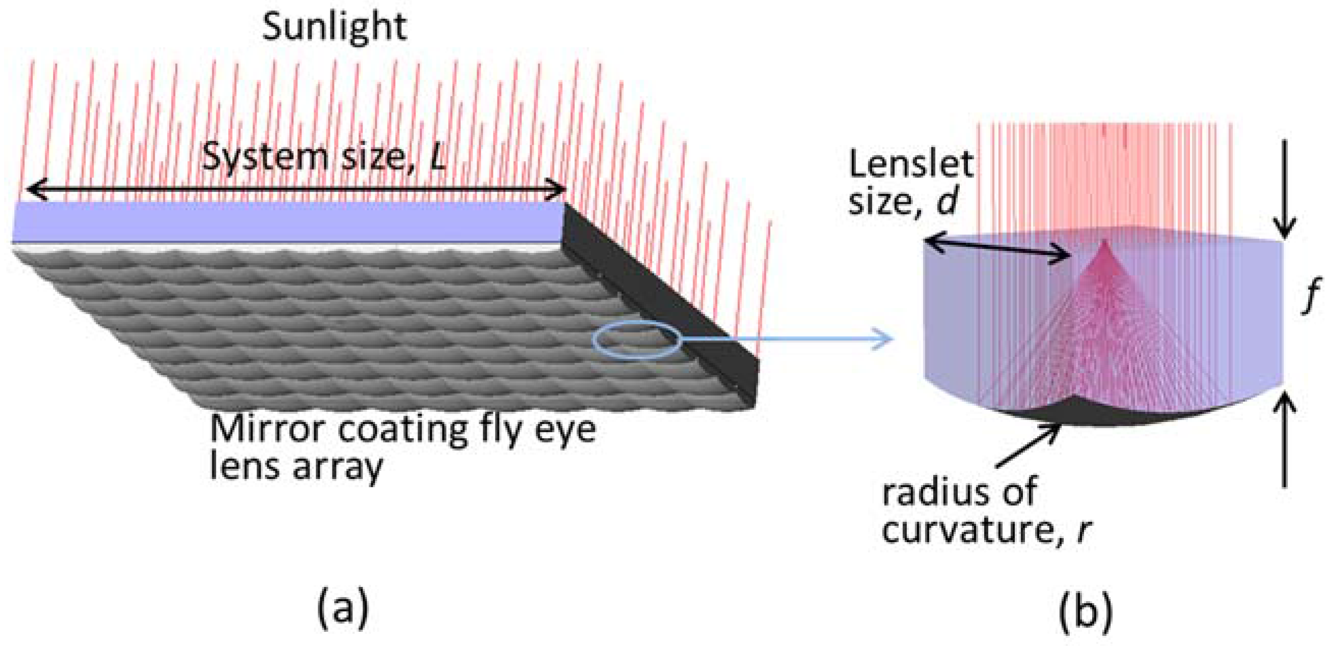
In this study, we introduce an alternative approach for a large-scale, flat CPV system comprised of an array of large-scale lenslets with mirror coating at the bottom and an array of solar cells integrated on a transparent substrate. The principles of CPV systems based on lenslet arrays are proposed in [5,8,11]; however, distance from lenslet to the focal point is long in comparison with its diameter. As shown in 
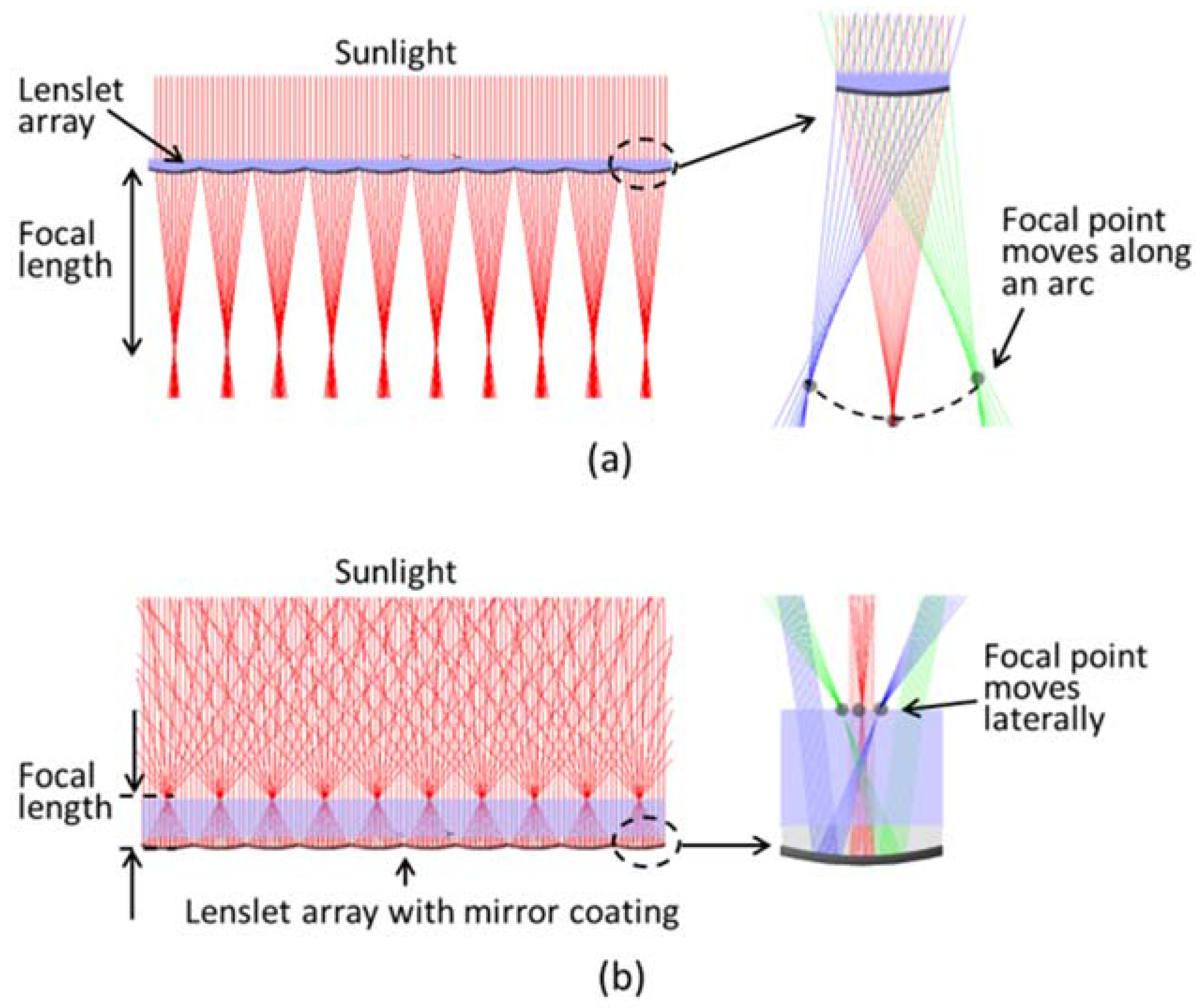
Figure 1a, in a larger-scale CPV system using an array of large-size lenslets, the system becomes very thick. The exaggerated part of Figure 1a shows the orbit of the focal point of each lenslet when the sunlight direction changes. The orbit of focal point of each lenslet is a arc. This does not allow for the use of a lateral displacement-tracking mechanism. Here, we propose a novel CPV system using amirror coated lenslet array. The mechanism of a solar concentrator based on mirror coated lenslet array is shown in Figure 1b. With this specialist design, sunlight is focused by a reflection mechanism instead of refraction in the conventional designs. The focal length can be sufficiently small, and the orbits of focal points are in a straight line (as shown in the exaggerated part of Figure 1b) instead of an arc (as in the exaggerated part of Figure 1a). With this design, the complex CPV system with cumbersome sunlight concentrator and rotation sun tracking mechanism could be replaced by a flat concentrator with lateral sun tracking mechanism. The aim of this research was to design and analyze a compact solar concentrator based on a mirror-coated lenslet array that might contribute to developing a high-efficiency, low-cost CPV system suitable for rooftop installation, thus facilitating the mass production and commercialization of cost-effective CPV systems.
The remainder of the paper is organized as follows: Section 2 discusses in detail the design of the proposed flat CPV system based on a mirror-coated lenslet array. In Section 3, the proposed system has been modeled using LightTools software (Synopsys, Inc., San Diego, CA, USA) to evaluate its performance. The requirements for lateral displacement and tolerance of sun-tracking systems are also discussed. Detailed discussion, technical issues, and cost factors are presented in Section 4. Finally, brief concluding remarks and possibilities for future research are presented in Section 5.

2. System Deign

This section presents the design of a flat CPV system with a lateral displacement sun-tracking system. Figure 2 shows the physical layout of our proposed CPV system. The solar concentrator is composed of mirror coated lenslet array. The receiver, which is placed on top of the concentrator, consists of a transparent layer and an array of solar cells on the top surface. The concentrator is fixed, and the receiver can slides freely on the flat surface of the lenslet arrays. The gap between the concentrator and receiver is filled by transparent fluid as lubricant that is also index-matched to reduce Fresnel reflection losses at the gap region. Detail of each part in the proposed system is discussed below.

2.1. Static Solar Concentrator

In conventional CPV systems, the primary concentrator has a long focal length that is not suited to the design of a flat CPV system. In this study, the primary concentrator is constructed from a large-scale array of polymethyl methacrylate (PMMA) lenslets, as shown in Figure 3a. A conventional lenslet array consists of a set of lenslets in one plane. Each lenslet usually has the same focal length. Such lenslet arrays have many uses, but they are commonly found in Shack–Hartmann wavefront sensors and in beam homogenization optics for projection systems. Each element of lenslet array is an plano convex lens so its focal length can be calculate by simple equation: f = R/(n − 1) ≅ 2R, where n = 1.49 is the refractive index of PMMA, and R is the radius of curvature. In this study, A mirror coated layer is coated on the curvature surface of lenslet array so each lens play as a concave mirror with focal length can be calculated by f = R/2. It means the focal length of system reduced four times in our proposed design. Short focal length of concentrator shows the basic for designing a flat CPV system.
Figure 3 shows the design of statics concentrator based on mirror coated lenslet array with the association with some main parameters. The main parameters include system thickness (focal length), f; curvature radius of lens, r; the size of lenslet, d; size of concentrator, L. In our optical design and simulations, the lenslet array consists 100 lenslets with radius of curvature of r = 75 and size of d = 50 mm. They are arranged in a rectangular array as shown in Figure 3a such that the total size of static solar concentrator is L = 500 mm and its thickness is 35 mm (thickness of system is equivalent with the focal length). The size of concentrator and each lenslet can be selected freely. However, for the purpose of installation on the roof the thickness of system should be similar to thickness of typical flat PV panel. For the purpose of designing a flat CPV system for rooftop installation, a lenslet size of d = 50 mm and r = 75 mm is reasonable.

2.2. Receiver

The receiver is composed of an array of solar cells integrated on a transparent sheet, which gathers solar radiation and converts it to electricity. As shown in Figure 2, this part is placed on top of the primary concentrating lens array. The concentrator comprises a 10 × 10 array of lenslets, giving a focused region of 100 points, also arranged in the square array, on the focal plane. The use of a lenslet array has several inherent disadvantages, including dispersion of the solar spectrum when the sunlight direction deviates from the axis of the lenslets. The concentration ratio of the sytem is calculated by the ratio of the focused area to the lenslet area. Ray tracing function of LightTools software was applied to analyze the distribution of sunlight on the focal plane. The sunlight source used in the analysis was within the range of 200–2500 nm. The distribution of concentrated solar radiation on the focal plane is shown in Figure 4a. Figure 4b illustrates schematically how the sunlight beam passes through a lenslet and shows its dispersion. The sunlight is dispersed at the focal plane of the lenslet array because of the wavelength’s dependence of the refractive index of the lens material. The focused area also defines how large the sun image will be at the focal region and is a design parameter for the receiver part.
When the sunlight direction changes the distribution of sunlight on the focal plane also changed. We used ray tracing analysis to quantify the dependence of sunlight concentrated shape on the sunlight direction. Several simulations were carried out with sunlight deviations of θ = 0°, 30°, 45°, 60°. Figure 4c shows the variation in the sunlight distribution at the focal region. For the sizes of the focused areas, we obtained divergences of 4, 5.9, 7.1, and 9.7 mm, respectively. In order to collect all of the concentrated sunlight input, the size of solar cells must be larger than the size of sunlight concentrated area. Although using large size of the solar cells will increase the acceptance angle of the sunlight direction, but it will also reduce the concentration ratio of the system. As shown in Figure 4c, when the sunlight angle is 45°, the concentration spot have size of 7.1 mm. In our proposed design, we selected the solar cells which are squares of 7.1 mm × 7.1 mm corresponding to a sunlight acceptance angle of 45°. Base on definition of concentration ratio which is ratio between sunlight collecting area and solar cell area, the concentration ratio, Cgeo of our proposed design is given by
C g e o = Lenslet   Area Solar   Cell   Area = 50   mm × 50   mm 7.1   mm × 7.1   mm 50
The proposed flat CPV system achieves a concentration ratio of approximately 50×, categorized as medium-level concentration. Silicon concentrator solar cells (c-Si solar cells) are particularly well suited to utilizing concentrated light in medium (30–100×) concentration ranges. This type of solar cell can convert sunlight directly into electricity, with a maximum reported laboratory-scale cell efficiency of ~23% [10,12]. The index-matched oil is inserted into the thin gap between the concentrator and receiver. We suggest using a transparent oil of a high refractive index, which is commonly used in light microscopy. The receiver is intended to be equipped with a two-axis planar tracking system to collect sunlight from different directions during the course of the day. The optical efficiency and sun-tracking performance of the proposed system are discussed in Section 3.

3. Simulation Results and Discussion

3.1. Optical Efficiency

We used commercial optical simulation software LightTools to design and model the proposed flat CPV. In the designed systemthe static solar concentrator is made of PMMA and the transparent layer of receiver is made of glass. The coupling region between the receiver and concentrator parts was filled with index-matching fluid with a matching refractive index of n = 1.51. For the simulation, the curvature surface of the concentrator (lenslet array) was assumed to be mirror-coated with a reflection coefficient of 96%. Optical losses in the system were simulated by modeling 100 optical power detectors as output optical receivers at the positions of the focused regions. The input optical receiver is a large plane that can cover the total area of the system. The simulation scheme is described in Figure 5. The optical losses of system include the Fresnel reflection losses, material absorption, and reflection loss at the mirror. It is very difficult to model these losses individually. However, the LightTools software can provide a simulation model that is similar to a virtual experiment; thus all kinds of losses were taken into account in the simulation. Some other losses that will appear in real conditions, such as the misalignment between optical elements, the impurities in optical material, degradation, and so forth, could not be calculated by simulation. These issues will be considered in future work when we create the prototype and perform the experiments. The optical efficiency, ηoptics, is simply defined as the ratio of the optical power on receiver to the optical power on the surface of solar concentrator:
η o p t i c s = Optical   power   on   output   receivers Optical   power   on   input   receiver
Simulations were conducted with sunlight at angles of 0°–45° at 5° increments. The dependence of the optical efficiency on the sunlight direction is illustrated in Figure 6. The optical efficiency decreases slightly when the sunlight direction θ increases. This is attributed to Fresnel reflection losses, which occur at the boundaries where light passes between regions with differing refractive indices; as such, the loss depends on the incident angle of light and the difference in refractive indices. In this design, Fresnel losses occur at the surface of the receiver, the gap between the concentrator and receiver, and the surface of the solar cells. The Fresnel loss at the conjunction between the concentrator and receiver can be reduced to <0.1% by filling with index-matched gel. Another system loss is the shading of solar cells and electrical wiring connections between them, estimated at approximately 3%. As shown in Figure 6, the system achieved an average optical efficiency of 89.5%.

3.2. Sun-Tracking Platform

For proper operation of the proposed flat CPV system, the solar cells should always align at the same position of sunlight focused area. Maintaining operation of CPV system as the sun moves East to West over the course of each day and North to South throughout the year is not a simple task for every CPV system. Most CPV systems are require precise sun tracking mechanism [7]. As discussed above, the proposed flat CPV system can implement tracking by lateral movement of the receiver part with respect to the lenslet array layer. Therefore, this lateral displacement form of tracking avoids the need to rotate the entire CPV system and reduces the complexity of the sun-tracking hardware. Consequently, this mechanism reduces the size and complexity of the sun tracking mechanisms at the cost of additional constraints on optical design.
To explore the proposed tracking mechanism, we aligned fat CPV system as shown in Figure 7. The input surface of the system is aligned normal to the sunlight direction at the highest elevation of the day and year. The moving part of the system (receiver) is mounted with a two-axis lateral tracking system. Two important parameters of the lateral sun tracking system are its amplitude of translation and tolerance. To determine the amplitude of translation, we examined the focal point positions at different angular deviations of sunlight within the range of acceptance angle of ±45°. Figure 8 shows the dependence of the lateral displacement of the focal point on the incident angle of sunlight within the range ±45°. Because the range of sunlight direction along North and South is from −23.5° to 23.5° so the lateral movement of receiver part along this direction is only 19 mm. The azimuth angle of the sun position varies by 180° daily, but the acceptance angle of the system is limited to ±45°; therefore, the working time of the system is limited to about 8 h per day in the summer. The movement amplitude of daily tracking is about 37 mm. Along East–West direction, the sun moves 180° daily, however the acceptance angle of our designed system is only ±45° therefor system only works from 8 a.m. to 4 p.m. in the summer day. The working time reduce in the other seasons. The movement of sun tracking along this direction is about 37 mm.
Tracking systems have been developed with the goal of maintaining precise alignment between concentrated sunlight regions and solar cells as the sun moves, thus maximizing the optical efficiency of the system. The tolerance of the system refers to the acceptable misalignment of the sunlight-focused region and the solar cell, within the allowable efficiency loss, and is defined as the misalignment at which the optical efficiency drops by 10% [11,13]. The acceptance of misalignment determines the required accuracy of the tracking system employed by the CPV system. The dependencies of the optical efficiency of the system on the misalignment along the two axes of the sun-tracking system are similar because the system is geometrically symmetrical. We examined the efficiency with different misalignments along one direction only. As mentioned above, the solar cells have sides of 7.1 mm. At the incident angle θ = 0°, the size of the sunlight-focused area is much smaller than at θ = 45° (4.0 and 7.1 mm, respectively), and the acceptance of the misalignment is much greater, as illustrated in Figure 9. The calculated acceptance of misalignment δ for θ = 45° represents the tolerance of the system.
Figure 10 shows the dependence of the normalized optical efficiency on the misalignment δ when the incident sunlight is at θ = 45°. The variations of efficiency on the left and right side of misalignment are different because the distribution of the sunlight at the focused area is not symmetrical. As shown in Figure 10, the acceptance of misalignment for the left side is 1.71 mm, compared with 0.9 mm for the right side. The smaller value, 0.9 mm, is selected as representative of the tolerance of the sun-tracking system. Conventional CPV systems use an active sun-tracking mechanism that controls motors via algorithms, combined with feedback control by optical sensors for measuring solar illumination. This mechanism generally exhibits high reliability and tracking accuracy, but it is complex and expensive. In our proposed CPV system, the high tolerance of 0.9 mm allows for the use of less precisestep-motors.

4. Discussion

Providing a cost-effective system is the major challenge for achieving the wider adoption of CPVs. As discussed in the introduction, to be competitive, a CPV system must be fabricated using a low-cost process. Accordingly, they must be manufactured using plastic materials. The use of plastic allows the lenslet array to be molded, thereby providing a low-cost solution for mass production. Reducing the use of materials will also contribute to reducing the costs of manufacturing, supplier management, and recycling. In our system design, the receiver and concentrator are made of a single material—PMMA.
Our proposed system has a lower concentration ratio (Cgeo = 50×) in comparison with typical Fresnel-based CPV systems (Cgeo is from 300× to 1000×), thereby requiring a larger solar cell area. Nevertheless, despite this comparative cost increase for additional solar cells, the declining unit cost of solar cell production means the system cost remains acceptable. On the other hand, the high concentration ratio of conventional designs requires very high-quality optical devices and sun-tracking systems. Very close alignment is also required between optical components, and these can rapidly become misaligned when operating under outdoor conditions [12,14]. Heat is also a problem in high-concentration systems, the remediation of which involves an additional cost. The highly condensed and non-uniform profile of light at the focused area in conventional systems requires a complicated and lossy optical system for the redistribution of light, which results in a lower efficiency and higher cost. Because of a lower concentration ratio in our proposed design, the heat problem becomes the minority.
As discussed in the introduction part, to be competitive, the flat CPV system must be efficient and must be fabricated using a low-cost process. The concentrator, which is an array of lenses, can be manufactured by a simple molding process. The fabrication of the receiver part, which is composed of a solar cell array integrated on a transparent sheet, seems not to be easy. We suggest using transparent light-emitting diode (LED) display technology; however, the LED chips will be replaced by solar cells. The LED display on a glass substrate was commercialized with a low cost and has been widely applied for decorative lighting or displays recently [15]. 
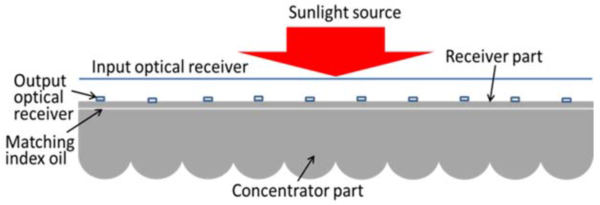
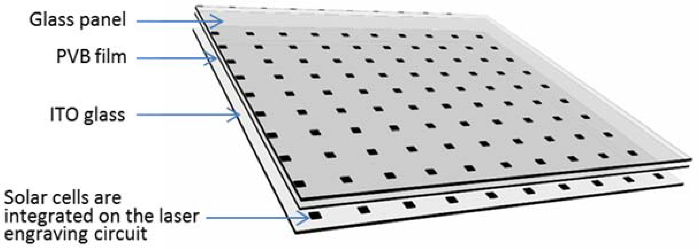
Figure 11 shows the structure of a receiver constructed on the basis of this technology. The receiver is composed of indium tin oxide (ITO) conductive glass, solar cells and a glass panel. ITO coated glass is often used for displays and touch screens. The solar cell array is glued onto a conductive glass. The solar cells on the conductive glass are electrified through the method of laser ablation. No electrical wire is utilized in this method; hence the shadow of the electric wire is eliminated. A glass plate is placed on the upper to protect the degradation under outdoor conditions. Two layers are glued together using a polyvinyl butyral (PVB) film, which is a resin mostly used for adhesion to many surfaces. In [16], the thermal conductivity of the ITO layer is 4–5.86 W/mK, while the thermal conductivity of the glass is 0.8 W/mK and of the PMMA is 0.167–0.25 W/mK; thus this ITO layer also plays the role of a heat dissipation layer. Because the solar cells are placed on the top of the CPV system, we propose coating a thin layer of silver as an additional heat sink.
Because of the simplicity of the proposed flat CPV system in terms of its shape, weight, operating principle, and cost, it can easily be installed on rooftops. The adoption of flat CPVs for rooftop installation will address the apparent huge demand for commercialization [17]. The aim of the present research is to design a flat CPV system suitable for residential rooftops; therefore, a brief comparison between our proposed system and widely used PV panels is essential. Most PV panels have an electricity conversion efficiency of 18–20% as a result of using Si solar cells with a multi-crystalline structure. Our proposed system utilizes single-crystalline Si solar cells with an efficiency of 25%; considering optical losses (~10%), the overall system efficiency is approximately 22.5%. Unlike traditional or more conventional flat-panel systems, our proposed flat CPV system is much less expensive to produce, as each cell requires much less semiconductor material than conventional solar cells, which also makes the system more environmentally friendly. Sunlight has two components: direct normal irradiance (DNI) and diffuse horizontal irradiance (DHI). As for most concentration systems, our proposed flat CPV system is unable to collect diffuse irradiation. This is a drawback in comparison with flat PV systems. There have recently been rapid developments in transparent solar cell technology. A transparent solar panel can absorb both the ultra violet and infrared parts of the solar spectrum to generate electricity. This type of solar cell is transparent to the visible spectrum. We suggest that the transparent PMMA sheet used in the receiver part of our proposed system might be replaced by a transparent solar panel and the solar cell arrays be replaced by double-junction solar cells baed on GaInP/GaInAs, which have the highest conversion efficiencies within the visible spectrum. This would allow the non-visible components of both DNI and DHI to be collected and converted to electricity, and visible irradiation—the largest portion of solar energy—will be concentrated and converted by high-conversion-efficiency solar cells. The approach of combining with transparent solar cells, as discussed here, may provide a new path for efficient, compact, and inexpensive PV power.

5. Conclusions

A large-scale flat CPV system using a mirror-coated lenslet array with a lateral displacement tracking mechanism has been designed and discussed for rooftop installation as an alternative to flat PV panels. Simulation results show that system can achieve optical efficiency of 89.5% at Cgeo = 50×. The lateral displacement method of sun-tracking shows a very high tolerance, allowing for the use of a less-accurate and -costly tracking system (such as passive sun-tracking on the basis of the known equations of solar motion). This is the first study to use a mirror-coated lenslet array for a flat CPV system. The proposed system is highly suited to large-scale production and rooftop installation and shows great potential for commercial-scale and industrial-scale solar energy systems. Future studies will make a prototype of flat CPV system and evaluate its performance under real conditions.

Acknowledgments

This work was supported by the National Research Foundation of Korea (NRF) grant funded by the Korea government (MSIT) (No. 2017R1C1B5017659) and 2017 Research Fund of Myongji University.

Author Contributions

Ngoc Hai Vu conceived and developed the original ideas. Ngoc Hai Vu carried out the performance analysis and simulations and wrote the paper. Seoyong Shin supervised the research and finalized the paper.

Conflicts of Interest

The authors declare no conflict of interest.

References

  1. Mojiri, A.; Taylor, R.; Thomsen, E.; Rosengarten, G. Spectral beam splitting for efficient conversion of solar energy—A review. Renew. Sustain. Energy Rev. 2013, 28, 654–663. [Google Scholar] [CrossRef]
  2. Steiner, M.; Kiefel, P.; Siefer, G.; Wiesenfarth, M.; Dimroth, F.; Krause, R.; Gombert, A.; Bett, A.W. CPV module design optimization for advanced multi-junction solar cell concepts. AIP Conf. Proc. 2015, 1679. [Google Scholar] [CrossRef]
  3. Steiner, M.; Siefer, G.; Schmidt, T.; Wiesenfarth, M.; Dimroth, F.; Bett, A.W. 43% Sunlight to Electricity Conversion Efficiency Using CPV. IEEE J. Photovolt. 2016, 6, 1020–1024. [Google Scholar] [CrossRef]
  4. Willis, B. Soitec Reaches 38.9% Conversion Efficiency with CPV Module; PV-Tech News Letter; PV-Tech: London, UK, 2015. [Google Scholar]
  5. Philipps, S.P.; Bett, A.W.; Horowitz, K.; Kurtz, S. Current Status of Concentrator Photovoltaic (CPV) Technology; National Renewable Energy Laboratory (NREL): Springfield, VA, USA, 2015.
  6. Duerr, F.; Meuret, Y.; Thienpont, H. Tracking integration in concentrating photovoltaics using laterally moving optics. Opt. Express 2011, 19 (Suppl. 3), A207–A218. [Google Scholar] [CrossRef] [PubMed]
  7. Hallas, J.M.; Baker, K.A.; Karp, J.H.; Tremblay, E.J.; Ford, J.E. Two-axis solar tracking accomplished through small lateral translations. Appl. Opt. 2012, 51, 6117. [Google Scholar] [CrossRef] [PubMed]
  8. Dhakal, R.; Lee, J.; Kim, J. Bio-inspired thin and flat solar concentrator for efficient, wide acceptance angle light collection. Appl. Opt. 2014, 53, 306–315. [Google Scholar] [CrossRef] [PubMed]
  9. Price, J.P.; Giebink, N. Concentrating photovoltaic panels for the rooftop. SPIE Newsroom 2015, 2, 2–4. [Google Scholar] [CrossRef]
  10. Price, J.S.; Sheng, X.; Meulblok, B.M.; Rogers, J.A.; Giebink, N.C. Wide-angle planar microtracking for quasi-static microcell concentrating photovoltaics. Nat. Commun. 2015, 6, 6223. [Google Scholar] [CrossRef] [PubMed]
  11. Bouchard, S.; Thibault, S. Planar waveguide concentrator used with a seasonal tracker. Appl. Opt. 2012, 51, 6848. [Google Scholar] [CrossRef] [PubMed]
  12. Rand, B.P.; Genoe, J.; Heremans, P.; Poortmans, J. Solar cell efficiency tables (version 37). Prog. Photovolt. Res. Appl. 2010, 15, 659–676. [Google Scholar] [CrossRef]
  13. Vu, N.; Shin, S. A Large Scale Daylighting System Based on a Stepped Thickness Waveguide. Energies 2016, 9, 71. [Google Scholar] [CrossRef]
  14. Vu, N.-H.; Shin, S. Cost-effective optical fiber daylighting system using modified compound parabolic concentrators. Sol. Energy 2016, 136, 145–152. [Google Scholar] [CrossRef]
  15. Wooscreen LED Smart Glass. Available online: http://www.wooscreen.com/index.php?c=content&a=show&id=61 (accessed on 15 November 2017).
  16. Ashida, T.; Miyamura, A.; Oka, N.; Sato, Y.; Yagi, T.; Taketoshi, N.; Baba, T.; Shigesato, Y. Thermal transport properties of polycrystalline tin-doped indium oxide films. J. Appl. Phys. 2009, 105. [Google Scholar] [CrossRef]
  17. Vu, N.; Shin, S. A Concentrator Photovoltaic System Based on a Combination of Prism-Compound Parabolic Concentrators. Energies 2016, 9, 645. [Google Scholar] [CrossRef]
Figure 1. (a) Solar concentrators based on conventional lenslet array have a very long focal length. (b) A solar concentrator using a mirror-coated lenslet array concentrates sunlight on the basis of a reflection mechanism and has a short focal length.
Energies 11 00114 g001
Figure 2. Physical layout of flat concentrated photovoltaic (CPV) system, using mirror-coated lenslet array as a static concentrator and a solar cell array integrated on a transparent sheet as a laterally moveable receiver.
Energies 11 00114 g002
Figure 3. The structure of a static solar concentrator: (a) Three-dimensional (3D) view of a mirror-coated lenslet array and associated parameters; (b) details of ray-tracing analysis on a single mirror-coated lenslet.
Energies 11 00114 g003
Figure 4. Concentrated sunlight distribution on the focal plane of concentrator (a) Three-dimensional (3D) view of light distribution on a receiver placed at focal plane of concentrator, (b) mechanism of dispersion inside a single lenslet, and (c) the expansion of sunlight distribution at the focal area with different sunlight deviations.
Energies 11 00114 g004
Figure 5. Illustration of the simulation scheme for analyzing optical efficiency of the designed system.
Energies 11 00114 g005
Figure 6. Optical efficiency depends on the incident angle of sunlight.
Energies 11 00114 g006
Figure 7. Alignment of the system along the north–south (N–S) and east–west (E–W) directions.
Energies 11 00114 g007
Figure 8. Dependence of displacement of focal point on incident angle of sunlight within the range from −45° to 45°.
Energies 11 00114 g008
Figure 9. Illustration of the misalignment between sunlight-focused area and solar cell for θ of 0° and 45°.
Energies 11 00114 g009
Figure 10. The dependence of normalized optical efficiency on misalignment δ when incident sunlight is at θ = 45°.
Energies 11 00114 g010
Figure 11. Receiver part of proposed system composed of indium tin oxide (ITO) glass, solar cells and glass panel is fabricated on the basis of transparent light-emitting diode (LED) display technology.
Energies 11 00114 g011

