Article

Influence of Stator MMF Harmonics on the Utilization of Reluctance Torque in Six-Phase PMA-SynRM with FSCW

Department of Electrical Engineering, Harbin Institute of Technology, Harbin 150080, China
*
Author to whom correspondence should be addressed.
Energies 2018, 11(1), 108; https://doi.org/10.3390/en11010108
Submission received: 28 October 2017 / Revised: 25 December 2017 / Accepted: 26 December 2017 / Published: 3 January 2018

Abstract

:
Although fractional-slot concentrated winding (FSCW) offers many significant advantages, such as short end-turn windings, high slot filling factor, and low cogging torque, it is frequently limited by excessive stator magnetomotive force (MMF) harmonics which will induce high eddy losses in the permanent magnets (PMs). What is more, in the literature, it can be observed that the reluctance torque of the salient-pole machine with FSCW is usually much lower than that obtained with integral slot winding. To explore the underlying reason why the reluctance torque in a salient machine with FSCW significantly decreases, a new six-phase FSCW with 24 slots and 10 poles, which can significantly reduce the undesirable stator MMF harmonics, is obtained by using the concept of stator shifting. Then, two permanent-magnet-assisted synchronous reluctance machines (PMA-SynRMs) with the proposed winding layout and conventional asymmetric 12-slot/10-pole six-phase winding layout are designed and simulated by the finite-element method (FEM). The reluctance torque, total torque, and d/q-axis inductances with different current phase angles are also compared under different loaded conditions. The results show that a reduction in stator MMF harmonics can indeed lead to a significant enhancement in reluctance torque under heavy loaded conditions, while the dominance will diminish under light loaded conditions.

1. Introduction

Nowadays, owing to its high torque density and high efficiency, the rare-earth permanent-magnet (PM) (such as NdFeB) synchronous machine (PMSM) is widely used for industrial applications, such as electric vehicle (EV) traction application [1,2,3]. Unfortunately, the volatile price of NdFeB after 2011 as well as a limited flux-weakening capacity have immensely limited their further development for EV applications, which require a low cost and a wide speed range [4]. For this reason, owing to their advantages such as mature technology, robust structure, relatively low cost, and excellent flux-weakening performance, induction machines (IMs) are often more competitive for EV applications [1]. However, the low efficiency and power factor of IMs increase the battery cost, which plays a dominant role in the whole EV cost.
To balance the performance and cost, permanent-magnet-assisted synchronous reluctance machines (PMA-SynRMs) are employed, which can not only reduce the amount of PMs by increasing the reluctance torque with a high saliency ratio, but also keep a relatively high efficiency due to the added PMs [5,6,7,8]. PMA-SynRMs with NdFeB were designed for EV applications in References [9,10]. To reduce the cost further, the use PMA-SynRMs with ferrite magnets has also attracted much attention. PMA-SynRMs with ferrite magnets, which have the same efficiency and power density as those with rare-earth magnets, were investigated in Reference [11]. However, the arc-shaped magnets increase the manufacturing difficulty and cost. Thus, a new PMA-SynRM with rectangular-shaped ferrite magnets was designed, taking the manufacturing problem into consideration [12].
Recently, due to its enhanced fault-tolerant capacity compared with a conventional three-phase machine, the multiphase machine has become a competitive candidate for safety-critical applications. Fractional-slot concentrated winding (FSCW) is always used together with a multiphase machine owing to its short end-turn windings, high slot filling factor, and low cogging torque [13,14]. Moreover, the inherent high self-inductance of FSCW can enhance its flux-weakening ability and fault-tolerant capacity. A PMA-SynRM equipped with multiphase FSCW seems to be very attractive for EV application. Unfortunately, FSCW often produces a large number of undesirable space harmonics in stator magnetomotive force (MMF), which induces significant eddy loss in PMs and thus decreases the efficiency and increases the irreversible demagnetization risk of the PMs [15,16]. What is more, several papers show that FSCW is not suitable for salient-pole machines because of its weak ability to output reluctance torque [17]. In Reference [18], four stators—two integral-slot distributed windings (ISDWs) and two FSCWs—were designed using the same interior PM rotor. The comparison results show that the reluctance torques of the interior PMSMs with FSCWs are much lower than those with ISDWs.
To improve the situation, it is necessary to suppress the MMF harmonics of the FSCWs. It has been reported that, for FSCW, an appropriate pole and slot combination will aid in the reduction of the MMF harmonics. In Reference [19], it was reported that asymmetrical six-phase winding with 30 degrees between the two three-phase windings has better MMF distribution than symmetrical six-phase winding. The paper therefore focuses on the selection of the fractional-slot winding, particularly the number of slots and poles necessary to achieve asymmetrical six-phase winding. The effect of the single- or double-layer FSCW on the MMF harmonics was investigated in Reference [20]. The study indicates that by employing double-layer winding type, the 24-slot/22-pole six-phase machine can effectively reduce the sub-harmonic compared with the single-layer one. Adding extra flux barriers in the no-winding teeth is also a technique used to reduce the MMF harmonics [21]. Some other winding topologies have also been proposed to reduce the MMF harmonics. Multilayer winding [22,23] and winding with different numbers of turns per coil side [24,25] were also employed to enhance the quality of the stator MMF distribution. These winding configurations significantly enhance the manufacturing cost. Reference [26] shows a new concept—the concept of stator shifting, in which the conventional 12-slot/10-pole three-phase machine is divided into two sets of three-phase winding and the final 24-slot/10-pole dual three-phase winding configuration is obtained by placing a right phase shift between the two sets of windings. The new 24-slot/10-pole winding can effectively reduce the MMF harmonics. Also, in recent literature, some new winding configurations, such as 24-slot/10-pole [27,28,29,30] and 18-slot/8-pole [31], which were developed from the conventional 12-slot/10-pole and 9-slot/8-pole winding configurations, have been proposed by employing the concept of stator shifting.
Although the new winding configurations after using the concept of stator shifting can significantly reduce the content of the MMF harmonics, they are rarely used in salient-pole machines. What is more, whether the optimized stator MMF distribution indeed improves the usage of the reluctance torque has not yet been fully investigated. In this paper, the 24-slot/10-pole six-phase winding, which was developed from the conventional 12-slot/10-pole six-phase winding using the same concept, is used in a PMA-SynRM. A PMA-SynRM equipped with the conventional 12-slot/10-pole six-phase winding is also designed. All of the parameters, such as the rotor dimensions, turns-per-phase, slot filling factor, inner and outer diameters, and stack length, are the same except the number of slots. The widths of the teeth are adjusted to the different numbers of slots in the stator. With the same rated current, the average torque, torque ripple, various loss components, and efficiency are compared. Then, with different current magnitudes, the total torque characteristics, the reluctance torques, and the inductances of the two machines under different current phase angles ψ (the leading angle of the current vector from the q-axis) are also compared. Finally, the different output capacities of the two machines are obtained, and may offer a possible way to enhance the reluctance torque in salient-pole machines. This paper aims to investigate the relationship between the stator MMF harmonics and the usage of the reluctance torque. Both the MMF harmonics and the reluctance torque can’t be measured directly by experiment. Therefore, the investigation is carried out using the finite-element method (FEM), which is expected to show the comparison more clearly and then, to give a fair judgment.

2. Winding Configurations and MMF Analysis

FSCWs that satisfy Q = 2p+/−2, where Q denotes the number of slots and p denotes the number of poles, are often employed by multiphase machines to maximize their winding factor and enhance their fault-tolerant capacity [32]. For a six-phase machine, the slot number is also required to satisfy Q = 6k, where k is a positive integer. Here, by way of example, 12-slot/10-pole machines with both three-phase and six-phase winding layouts are analyzed, as shown in Figure 1.
In Figure 1, it can be found that there is only one kind of six-phase winding configuration (Winding II) for a single-layer 12-slot/10-pole winding type, while there can be two different kinds of six-phase winding configurations for a double-layer winding type—symmetric six-phase (Winding IV) and asymmetric six-phase winding (Winding V). The symmetric six-phase windings with a 60-degree phase belt have electromagnetic features similar to a conventional 60-degree three-phase winding [33], as shown in Table 1. The symmetric six-phase windings (Winding II and Winding IV) possess the same winding factors and MMF distributions as the three-phase windings (Winding I and Winding III). For three-phase and symmetric six-phase windings, a double-layer winding type will lower the winding factor because the double layer winding will introduce an extra winding distribution factor. It should be highlighted that the content of MMF harmonics of 12-slot/10-pole asymmetric six-phase winding is almost half of the other four winding configurations. Moreover, its winding factor is not reduced, even though it is double-layer compared with the single-layer winding type. With the same ampere-turns, the simulated results of the MMF distributions of the five different winding configurations are obtained, as shown in Figure 2. For these 12-slot/10-pole machines, the 5th harmonic component is the working one and the others are all the undesirable harmonics. It can be seen that the main MMF harmonic orders of Winding I–IV are 1, 5, 7, 11, 13, 17, and 19 (satisfied with 6k ± 1 as shown in Table 1). For Windings III and IV, the magnitudes of the 5th harmonic (the working harmonic in a 5-pole-pair machine) are lower than the other three winding topologies because of their lower winding factors. But, Windings III and IV can greatly suppress the 1st harmonic compared with Windings I and II. As for Winding V, it not only produces a higher 5th harmonic, but also completely eliminates the 1st harmonic. With the aim of enhancing the quality of MMF distribution, Winding V is the best choice.
According to References [4,34], it can be found that for FSCWs, the most harmful MMF harmonics are those which are close to the fundamental harmonic (also called the synchronous harmonic in Reference [
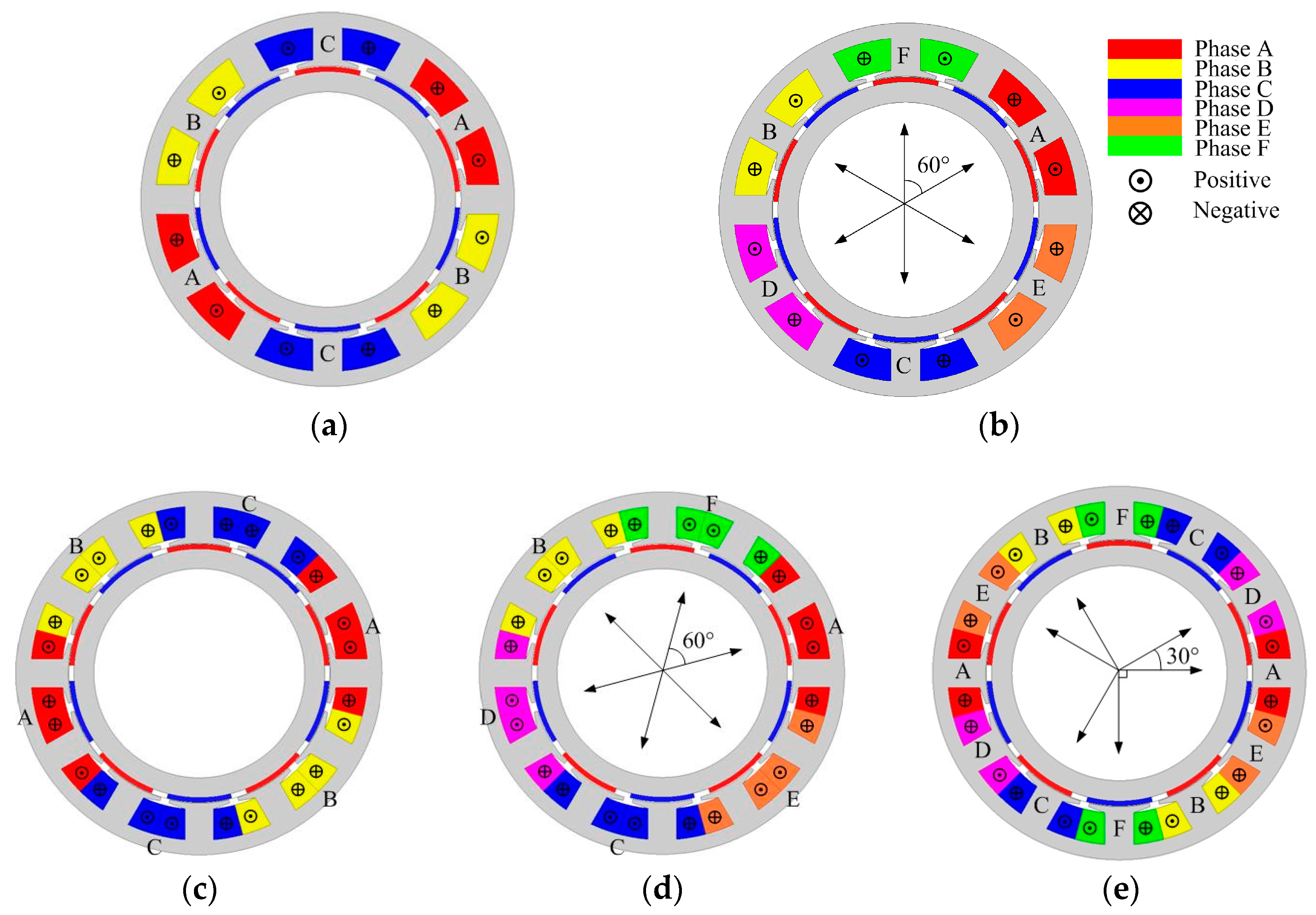
4]). Here, for a 5-pole-pair FSCW machine, the most harmful MMF harmonics will be the 1st and 7th harmonics, knowing that the fundamental harmonic is the fifth harmonic. Although Winding V can eliminate the 1st harmonic, the magnitude of the 7th one is still high, which will lead to serious PM eddy loss and then reduce the efficiency and increase the risk of irreversible demagnetization of the PMs. What is more, it will have a significant negative influence on the utilization of reluctance torque in a salient-pole machine. To cancel the 1st and 7th harmonics at the same time, the concept of stator shifting is employed, which is an effective way to suppress the undesirable MMF harmonics by using two FSCW stators with the same slot/pole combination to form a new stator. In this paper, due to its excellent stator MMF distribution, the concept of stator shifting is employed by 12-slot/10-pole asymmetric six-phase winding (Winding V), which implies that a 24-slot/10-pole machine with two sets of Winding V will be obtained, as shown in Figure 3. By increasing the coil pitch to two and doubling the number of the slots, two sets of Winding V can be placed in the new 24-slot stator. It should be noted that the 24-slot/10-pole configuration no longer satisfies the relation Q = 2p+/−2, so that its winding factor will significantly decrease if it still employs a tooth-coil winding (coil pitch equals 1).The second Winding V (as shown in Figure 3b) is obtained by shifting the first Winding V (as shown in Figure 3a) with a certain mechanical angle α. Different α results in different phase shifts between the two sets of windings which will lead to different winding factors and different stator MMF distributions.
Here, to avoid an uneven teeth stator, the angle α between the two stators is limited to (2k − 1)360°/Q, where k is a positive integer. Assuming that the magnitude of the 7th harmonic of one Winding V is F7, the sum of the 7th harmonic of the two sets of Winding V can be obtained as follows:
F s u m = F 7 cos 7 θ + F 7 cos 7 ( θ α ) = F 7 cos 7 θ + F 7 cos 7 ( θ ( 2 k 1 ) 15 ) = 2 F 7 cos ( 7 θ + 7 ( θ ( 2 k 1 ) 15 ) 2 ) cos ( 7 θ 7 ( θ ( 2 k 1 ) 15 ) 2 ) = 2 cos ( 7 ( 2 k 1 ) 15 ) 2 ) cos ( 7 θ ( 2 k 1 ) 52.5 ) = 2 cos ( ( 2 k 1 ) 52.5 ) cos ( 7 θ ( 2 k 1 ) 52.5 )
It can be seen from (1) that the magnitude of the 7th harmonic will be minimum when the value of cos((2k − 1)52.5°) is minimum. When k is 3 or 10, the value of cos((2k − 1)52.5°) reaches the lowest value. When k is 3 or 10, the angle α is 75° or 285°. Then, the MMF distributions with different values of α are simulated by FEM. For the “combined” 24-slot stator, there will be 12 different values of α, as listed in 
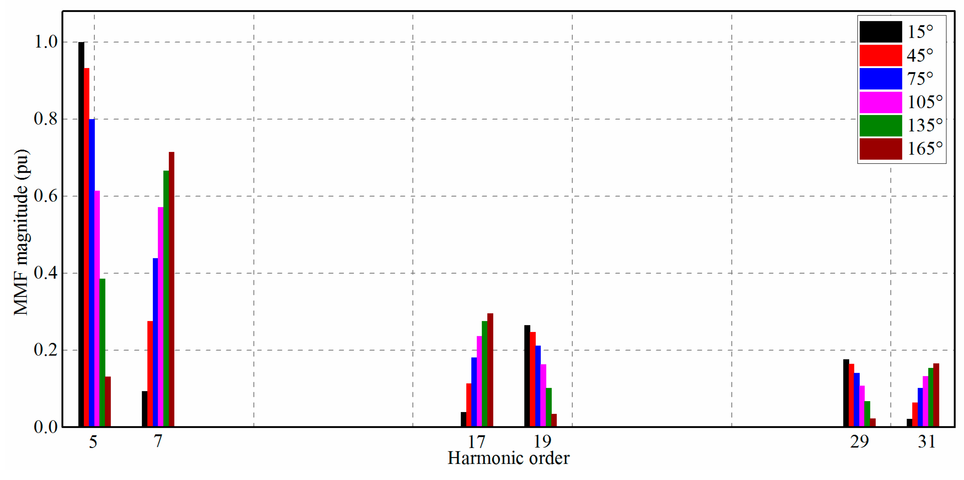
Table 2. By analyzing the phasor diagrams of all 12 schemes, the phase shifts between the two sets of windings are reduced to six different schemes. The stator MMF distributions of the six different phase shifts are shown in Figure 4, and their corresponding harmonic spectra are shown in Figure 5. Firstly, it can be clearly seen that the different phase shifts will indeed have a significant influence on the stator MMF distributions. In Figure 5, it can be found that all six schemes can cancel the 1st harmonic, owing to the advantage of Winding V. The magnitude of the 7th harmonic reaches the lowest value of 0.094 pu when the phase shift is 15°. It can be also found that the different phase shifts will result in different 5th harmonics (the working harmonic) which implies different winding factors. The winding factors with different phase shifts are listed in Table 3.
It can be seen that the winding factor will reach the highest value of 0.958 when the phase shift is 15°, so the magnitude of the 5th harmonic is the highest when the phase shift is 15°, as shown in Figure 5. The winding factor of Winding V is 0.966. This is to say that the proposed 24-slot/10-pole scheme with a phase shift of 15° between the two sets of Winding V can significantly suppress the 7th harmonic with just a little reduction in winding factor, compared with the 12-slot/10-pole with Winding V. Hence, the 15° phase shift is selected as the optimum phase shift and the corresponding winding layout is employed.

3. Machine Design and Specifications

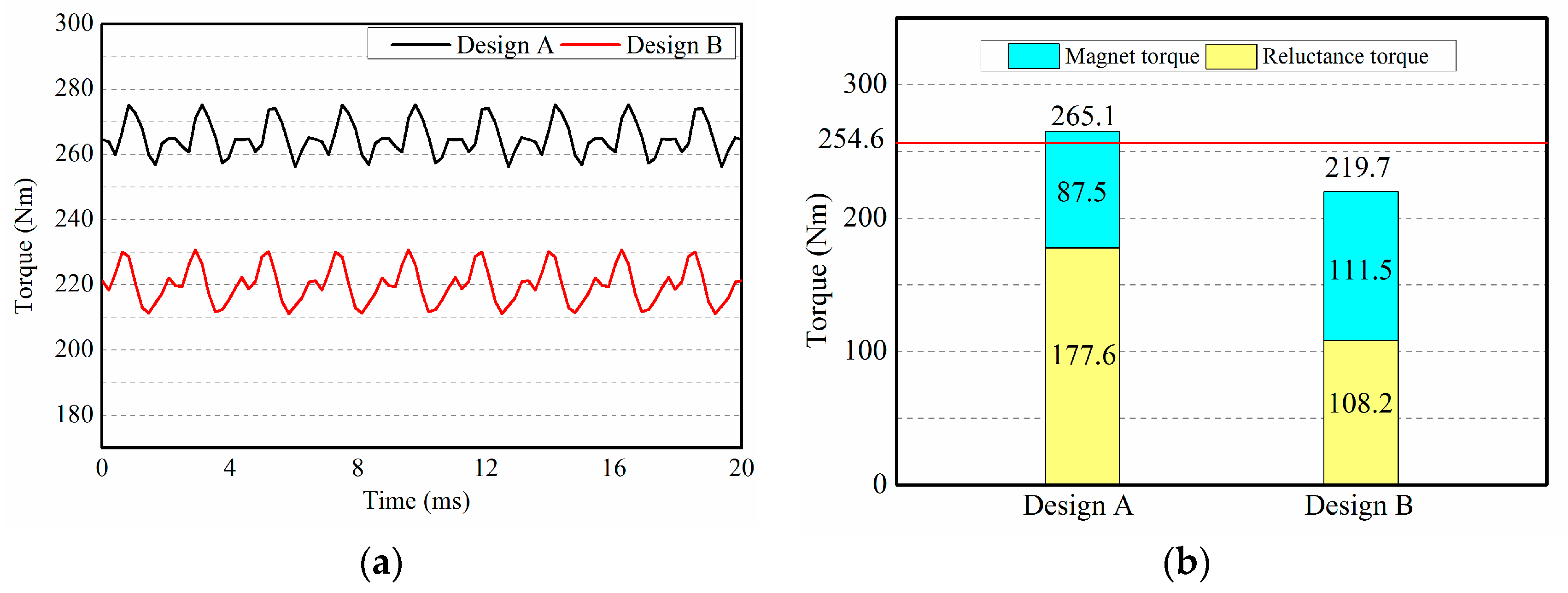
In this paper, to show that the reduction of MMF harmonics does not automatically lead to a reduction of the reluctance torque, two PMA-SynRMs whose reluctance torques are dominant components of the total torques are designed for comparison, as shown in Figure 6. The optimal 24-slot/10-pole six-phase winding investigated above is employed by Design A. The 12-slot/10-pole six-phase winding whose content of the stator MMF harmonic is relatively high is employed by Design B. For the sake of comparison, the same rotors are used for the two machines. The same stator inner and outer diameters are also used. In addition, the same turns per phase are also utilized. Although the widths of the stator teeth are adjusted to the different numbers of slots, the slot area and slot filling factor are still kept the same. The design specifications for the machines are listed in Table 4. The main dimensions are shown in Figure 6c and 
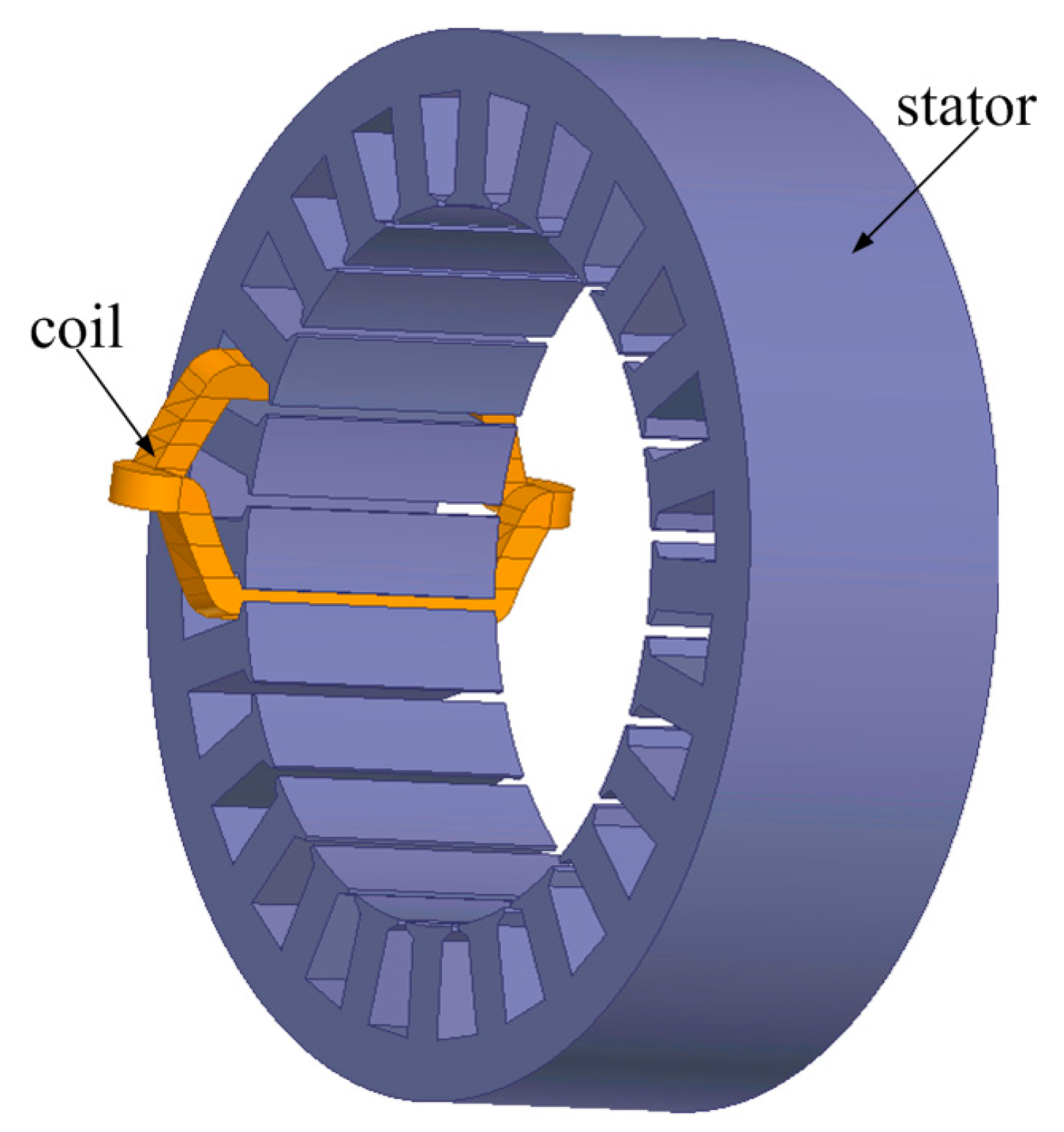
Table 5. For the sake of the relatively large amount of permanent magnet volumes, the cheap PM, a ferrite magnet (DM 4545) whose coercive force is 334 kA/m and remnant flux density is 0.45 T at 20 °C, is used. Also, to avoid increasing manufacturing costs, the PMs are rectangular-shaped. In Table 5, it can be found that the phase resistance of Design A is larger than that of Design B because the length of the coil of Design A is 500.4 mm, while it is only 426.4 mm in Design B, resulting from the longer end-windings of Design A. This is because Design A can no longer be tooth-concentrated due to its increased coil pitch, as shown in Figure 7.
With the same rated currents, the stator MMF distributions and their corresponding harmonic spectra are obtained, as shown in Figure 8. Design B produces a higher 5th harmonic (working harmonic) owing to its higher winding factor (0.966), in comparison to that produced in Design A (0.958). Both machines can completely eliminate the 1st harmonic. The magnitude of the 7th harmonic of Design A is greatly suppressed, as analyzed above, while it is still very high in Design B. The different magnitudes of the 7th harmonic of the two different machines result in different harmonic leakage inductances, which will finally make a difference to the reluctance torque outputting capacity.

4. Simulation Results and Performance Comparisons

In this section, the mathematical model of the PMA-SynRM is first established and the torque characteristics under different current phase are analyzed by employing the two-reaction theory. Then, the two designed PMA-SynRMs shown in Section 3 are simulated by two-dimensional (2-D) FEM. The performances, such as output torque, reluctance torque, and various losses, are compared at the rated point. Finally, to explore the ultimate causation of the different reluctance torque outputting capacity for the two machines, the total torques, reluctance torques, and the d/q-axis inductance characteristics versus current phase angle under both saturated and unsaturated situations are performed.

4.1. Mathematical Model and Analysis of Reluctance Torque

A PMA-SynRM can be regarded as a hybrid machine of an interior PMSM and a synchronous reluctance machine. In this paper, the same d-q reference frame system as that used in a PMSM is employed. The d-axis is aligned with the rotor magnetic center and the q-axis leads the d-axis by a 90° electrical angle, as shown in Figure 9a. By employing the two-reaction theory, the phasor diagram of one operating point (very light loaded condition) at steady state condition is obtained, as shown in Figure 9b.
From Figure 9b, the d-axis and q-axis currents can be obtained:
{ I d s = I s sin ψ I q s = I s cos ψ
where Ids denotes the magnitude of the d-axis current phasor, Iqs denotes the magnitude of the q-axis current phasor, Is denotes the magnitude of the phase current phasor, and Ψ denotes the leading angle of the current phasor from the q-axis (called the current phase angle in this paper). The following equations can be obtained:
{ U s sin θ = I q s ω L q s + I d s R s U s cos θ = E 0 I d s ω L d + I q s R s
where Us denotes the magnitude of the phase voltage phasor, θ denotes the leading angle of the voltage phasor from the q-axis, Lq denotes the q-axis inductance, Ld denotes the d-axis inductance, ω denotes angular frequency, E0 denotes the no-load back- electromagnetic force (EMF), and Rs is the phase resistance. The electromagnetic torque can be described as follows:
T e = m p I s U s cos φ ω
where m is the number of phases. Utilizing (2) and (3), (4) can be expressed as follows:
T e = m p I s U s cos φ ω = m p I s U s cos ( θ ψ ) ω = m p I s [ ( E 0 I d s ω L d + I q s R s ) cos ψ + ( I q s ω L q + I d s R s ) sin ψ ] ω = m p ω I s E 0 cos ψ + m p 2 I s 2 sin ( 2 ψ ) ( L q L d ) + m p ω I s 2 R s
In (5), it can be seen that the electromagnetic torque constitutes three components: the first component is the magnet torque, the second component is the reluctance torque, and the third component is the copper loss. Here, aiming at investigating the reluctance and magnet torque, the third component in (5) is ignored. It should be noted that Ld and Lq are obtained by using the phasor diagram shown in Figure 9b by injecting a tiny current. So, Ld and Lq are constant because of an unsaturation operating condition. The current phase angle versus the torque behaviors can be obtained as shown in Figure 10. It can be seen that the reluctance torque reaches its top value when the current phase angle is 45°. The magnet torque decreases with the increase of the current phase angle. So, the current phase angle which produces the maximum total torque must be between 0° and 45°.

4.2. Performances at Rated Point

By using the maximum torque per ampere (MTPA) control, the performances of the two machines are obtained at the same rated speed of 450 r/min. The torque waveforms are shown in Figure 11a. The magnet and reluctance torques are shown in Figure 11b. The average value and torque ripple of the two machines are listed in Table 6. It can be seen that, with the same rated current, 30 A (peak), the maximum torque of Design B (219.7 Nm), is much less than the required rated torque (254.6 Nm), while Design A can offer enough torque (265.1 Nm). What is more, the torque ripple of Design A is less than that of Design B. At this operating point, the reluctance torque of Design A is much more than that of Design B, as shown in Figure 11b, which results in different output capacities for the two different designs. The inductance saliency ratio ξ is defined as:
ξ = L q L d
This is also investigated in Figure 11c. The inductance saliency ratio of Design A is almost twice that of Design B. In conclusion, the large content of stator MMF harmonics of Design B reduces its inductance saliency ratio and thus reduces its reluctance torque.
The various losses are also listed in Table 6. It can be seen that the output power of Design B is much lower than that of Design A because of its lower output torque. Owing to its reduced MMF harmonics, the core loss of Design A is less than that in Design B. However, the copper loss of Design A is almost 100 W higher than that of Deign B because the phase resistance of Design A is bigger, as analyzed above. The efficiency of Design A is 94.2%, corresponding to a 0.6% improvement compared with Design B. It should be noted that the PM eddy loss is zero because the ferrite magnet is nonconductive. If rare-earth permanent magnets (NdFeB) are used, the difference between the efficiencies of Design A and Design B will be larger because the PM eddy loss of Design A will be much lower than that of Design B. Design A gains a reduction of 20.2% in phase voltage compared with Design B, which may lower the required direct-current-bus (DC-bus) voltage, thus reducing the battery cost. In conclusion, at rated operating point, the performances of Design A are better than those of Design B because of the higher reluctance torque produced by Design A. The performances under light loaded condition (5 A) are also obtained as shown in Table 7. With a lower current of 5 A, the maximum torque of Design B is higher than that of Design A owing to its higher winding factor. But, the efficiency of Design A is still higher than that of Design B.

4.3. Torque Characteristics under Different Loaded Conditions

It has been proved that the machine with less stator MMF harmonics (Design A) can output higher reluctance torque under a rated loaded condition. To investigate how the stator MMF harmonics function in reluctance torque utilization, the torque characteristics and the inductances of the two designed PMA-SynRMs under different current phase angles with the current magnitudes of 30 A and 5 A are performed, as shown in Figure 12 and Figure 13, respectively.
In Figure 12c, it can be seen that both Ld and Lq increase with the increase of the current phase angle for both Design A and Design B. This is to say that the rated current, 30 A (peak), induces significant saturations both in d-axis and q-axis magnetic roads in the two machines. Furthermore the saturation level of Design B is much higher than Design A, so the increment of Lq in Design B is smaller than it in Design A, thus resulting in a smaller difference between Lq and Ld in Design B, as shown in Figure 12c. Therefore, the maximum of reluctance torque provided by Design B is significantly lower than that provided by Design A, as shown in Figure 12b. With the same rotor, ampere turns, and similar winding factor for Designs A and B, the magnet torques of the two machines are almost the same. So, Design A can produce higher total torque under a maximum torque per ampere (MTPA) strategy with the same rated current, as shown in Figure 12a.
The current phase angle versus total torque, reluctance torque, and inductance with the current amplitude of 5 A are shown in Figure 13. In Figure 13c, it can be clearly found that the inductances of both machines are invariant with the current phase angle because they are both working under an unsaturated condition. What is more, the differences between Lq and Ld are almost the same in Design A and Design B, so the same reluctance torque can be obtained, as shown in Figure 13b. The q-axis and d-axis inductance can be expressed as follows:
{ L q = L a q + L 1 L d = L a d + L 1
where Lad denotes the d-axis armature reaction inductance, Laq denotes the q-axis armature reaction inductance, and L1 denotes leakage inductance. Under an unsaturated condition, the d/q-axis reaction inductances of the two designed machines are the same because they have the same turns per phase and magnetic roads. The different contents of the MMF harmonics of Design A and Design B only imply different harmonic leakage inductance as a part of L1, which has no effect on the difference between Lq and Ld under an unsaturated condition. So, the reluctance torque is irrelevant to the MMF harmonics under the unsaturated conditions. It should be noted that the total torque of Design B is slightly higher than that of Design A because of its higher winding factor.
Compared the results shown in Figure 12 and Figure 13, a preliminary conclusion can be made: under heavy loaded conditions, a high content of MMF harmonics will lead a larger reduction in inductances (especially Lq), which leads to a smaller difference between the q-axis inductance and the d-axis inductance, indicating a great reduction in reluctance torque. While under unsaturated conditions, the MMF harmonics have no effect on the reluctance torque.

5. Conclusions

(1)
For the 12-slot/10-pole combination, the asymmetric six-phase winding (Winding V) can not only produce a higher 5th harmonic, but also completely eliminate the 1st harmonic. Unfortunately, it has no effect on the most harmful MMF harmonic—the 7th harmonic.
(2)
By using the concept of stator shifting, the 24-slot/10-pole six-phase winding derived from the 12-slot/10-pole asymmetric six-phase winding is obtained. The various phase shifts between the two sets of 12-slot/10-pole asymmetric six-phase windings are compared. When the phase shift is 15°, the 24-slot/10-pole six-phase winding can reach the highest winding factor (0.958) and the lowest 7th harmonic (0.094 pu).
(3)
Two PMA-SynRMs with ferrite magnets using the new 24-slot/10-pole six-phase winding (Design A) and the conventional 12-slot/10-pole six-phase winding (Design B) are designed. The performances of Designs A and B are compared with the rated current by using the MTPA strategy. With less stator MMF harmonics in the air gap, Design A can indeed produce more reluctance torque than Design B. Moreover, owing to its lower MMF harmonics, the torque ripple is lower and the efficiency is higher.
(4)
It should be noted that, for the 24-slot/10-pole winding layout, increasing the coil pitch to two and doubling the number of the slots will complicate the manufacturing process and increase the copper loss. Moreover, the eddy-loss due to the slot effects will increase due to the increased slot number.
(5)
To investigate the influence of the stator MMF harmonics on the utilization of reluctance torque, the torque characteristics and the inductances of the two designed PMA-SynRMs under different current phase angles with the current amplitudes of 30 A and 5 A are carried out. The results show that, under heavy loaded conditions, a high content of MMF harmonics will induce deep saturation, which will have a significant negative effect on the utilization of reluctance torque. By contrast, under light loaded conditions, the reluctance torque is irrelevant to the stator MMF harmonics. This is to say that a high content of MMF harmonics has no negative effects on the utilization of reluctance torque under light loaded conditions. Since the experiment tests of the MMF harmonics and the reluctance torque are very difficult, the investigation is carried out using the FEM, which is expected to show the comparison more clearly.

Acknowledgments

This work was supported in part by the National Natural Science Foundation of China under Projects 51325701, 51637003, and 51607046, in part by the National Key R&D Program of China under Project 2017YFB0203600, in part by the Self-Planned Task (Nos. SKLRS201710A and 201504B) of State Key Laboratory of Robotics and System (HIT), in part by the China Postdoctoral Science Foundation funded project (2017M610204), and in part by the Fundamental Research Funds for the Central Universities (Grant No. HIT.MKSTISP.2016 24).

Author Contributions

This paper was a collaborative effort among all authors. All authors participated in the design of the proposed machine, in the comparison of the results with the conventional machine, and in writing the paper.

Conflicts of Interest

The authors declare no conflict of interest.

References

  1. Zhu, Z.Q.; Chan, C.C. Electrical Machine Topologies and Technologies for Electric, Hybrid, and Fuel Cell Vehicles. In Proceedings of the 2008 IEEE on Vehicle Power and Propulsion Conference, Harbin, China, 3–5 September 2008; pp. 1–6. [Google Scholar]
  2. Zhu, Z.Q.; Howe, D. Electrical Machines and Drives for Electric, Hybrid, and Fuel Cell Vehicles. Proc. IEEE 2007, 95, 746–765. [Google Scholar] [CrossRef]
  3. El-Refaie, A.M. Motors/Generators for Traction/Propulsion Applications: A Review. IEEE Veh. Technol. Mag. 2013, 8, 90–99. [Google Scholar] [CrossRef]
  4. Petrov, I.; Niemela, M.; Ponomarev, P. Rotor Surface Ferrite Permanent Magnets in Electrical Machines: Advantages and Limitations. IEEE Trans. Ind. Electron. 2017, 64, 5314–5322. [Google Scholar] [CrossRef]
  5. Lee, J.H.; Jang, Y.J.; Hong, J.P. Characteristic Analysis of Permanent Magnet-Assisted Synchronous Reluctance Motor for High Power Application. J. Appl. Phys. 2005, 97, 10Q503. [Google Scholar] [CrossRef]
  6. Niazi, P.; Toliyat, H.A.; Goodarzi, A. Robust Maximum Torque per Ampere (MTPA) Control for PM-Assisted SynRM for Traction Applications. IEEE Trans. Veh. Technol. 2007, 56, 1538–1545. [Google Scholar] [CrossRef]
  7. Guglielmi, P.; Boazzo, B.; Armando, E. Permanent-Magnet Minimization in PM-Assisted Synchronous Reluctance Motors for Wide Speed Range. IEEE Trans. Ind. Appl. 2013, 49, 31–41. [Google Scholar] [CrossRef]
  8. Jung, D.H.; Kwak, Y.; Lee, J.; Jin, C.S.M. Study on the Optimal Design of PMa-SynRM Loading Ratio for Achievement of Ultrapremium Efficiency. IEEE Trans. Magn. 2017, 53, 8001904. [Google Scholar] [CrossRef]
  9. Baek, J.; Rahimian, M.M.; Toliyat, H.A. Optimal Design and Comparison of Stator Winding Configurations in Permanent Magnet Assisted Synchronous Reluctance Generator. In Proceedings of the 2009 IEEE on Electric Machines and Drives Conference, Miami, FL, USA, 3–6 May 2009; pp. 732–737. [Google Scholar]
  10. Boldea, I.; Tutelea, L.; Pitic, C.I. PM-Assisted Reluctance Synchronous Motor/Generator (PM-RSM) for Mild Hybrid Vehicles: Electromagnetic Design. IEEE Trans. Ind. Appl. 2004, 40, 492–498. [Google Scholar] [CrossRef]
  11. Ooi, S.; Morimoto, S.; Sanada, M. Performance Evaluation of a High-Power-Density PMASynRM with Ferrite Magnets. IEEE Trans. Ind. Appl. 2013, 49, 1308–1315. [Google Scholar] [CrossRef]
  12. Ooi, S.; Morimoto, S.; Sanada, M. Performance of PMASynRM with Ferrite Magnets for EV/HEV Applications Considering Productivity. IEEE Trans. Ind. Appl. 2013, 50, 2429–2435. [Google Scholar]
  13. El-Refaie, A.M. Advanced High-Power-Density Interior Permanent Magnet Motor for Traction Applications. IEEE Trans. Ind. Appl. 2014, 50, 3235–3248. [Google Scholar] [CrossRef]
  14. Reddy, P.B.; EL-Refaie, A.M.; Huh, K.K. Effect of Number of Layers on Performance of Fractional-Slot Concentrated-Windings Interior Permanent Magnet Machines. IEEE Trans. Power Electron. 2014, 30, 2205–2218. [Google Scholar] [CrossRef]
  15. Barrero, F.; Duran, M.J. Recent Advances in the Design, Modeling, and Control of Multiphase Machines—Part I. IEEE Trans. Ind. Electron. 2016, 63, 449–458. [Google Scholar] [CrossRef]
  16. Wang, J.; Wang, W.; Atallah, K.; Howe, D. Demagnetization assessment for three-phase tubular brushless permanent-magnet machines. IEEE Trans. Magn. 2008, 44, 2195–2203. [Google Scholar] [CrossRef]
  17. Tangudu, J.K.; Jahns, T.M.; El-Refaie, A.M. Unsaturated and Saturated Saliency Trends in Fractional-Slot Concentrated-Winding Interior Permanent Magnet Machines. In Proceedings of the 2010 IEEE on Energy Conversion Congress and Exposition (ECCE), Atlanta, GA, USA, 12–16 September 2010; pp. 1082–1089. [Google Scholar]
  18. Tangudu, J.K.; Jahns, T.M. Comparison of Interior PM Machines with Concentrated and Distributed Stator Windings for Traction Applications. In Proceedings of the 2011 IEEEV on Vehicle Power and Propulsion Conference (VPPC), Chicago, IL, USA, 6–9 September 2011; pp. 1–8. [Google Scholar]
  19. Barcaro, M.; Bianchi, N.; Magnussen, F. Six-Phase Supply Feasibility Using a PM Fractional-Slot Dual Winding Machine. IEEE Trans. Ind. Appl. 2012, 47, 2042–2050. [Google Scholar] [CrossRef]
  20. Zheng, P.; Wu, F.; Sui, Y.; Wang, P.; Lei, Y.; Wang, H. Harmonic Analysis and Fault-Tolerant Capability of a Semi-12-Phase Permanent-Magnet Synchronous Machine Used for EVs. Energies 2012, 5, 3586–3607. [Google Scholar] [CrossRef]
  21. Dajaku, G.; Xie, W.; Gerling, D. Reduction of low space harmonics for the fractional slot concentrated windings using a novel stator design. IEEE Trans. Magn. 2014, 50, 8201012. [Google Scholar] [CrossRef]
  22. Reddy, P.; El-Refaie, A.M.; Huh, K.-K. Effect of number of layers on performance of fractional-slot concentrated-windings interior permanent magnet machines. IEEE Trans. Power Electron. 2015, 30, 2205–2218. [Google Scholar] [CrossRef]
  23. Wang, Y.; Qu, R.; Li, J. Multilayer windings effect on interior PM machines for EV applications. IEEE Trans. Ind. Appl. 2015, 51, 2208–2215. [Google Scholar] [CrossRef]
  24. Dajaku, G.; Gerling, D. Eddy current loss minimization in rotor magnets of PM machines using high-efficiency 12-teeth/10-slots winding topology. In Proceedings of the 2011 International Conference on Electrical Machines and Systems (ICEMS), Beijing, China, 20–23 August 2011; pp. 1–6. [Google Scholar]
  25. Dajaku, G.; Gerling, D. Different novel methods for reduction of low space harmonics for the fractional slot concentrated windings. In Proceedings of the 2012 International Conference on Electrical Machines and Systems (ICEMS), Sapporo, Japan, 21–24 October 2012; pp. 1–6. [Google Scholar]
  26. Dajaku, G. Elektrischemaschine. German Patent DE102008 057 349 B3, 15 July 2010. [Google Scholar]
  27. Dajaku, G.; Gerling, D. A novel 24-slots/10-poles winding topology for electric machines. In Proceedings of the 2011 IEEE International on Electric Machines & Drives Conference (IEMDC), Niagara Falls, ON, Canada, 15–18 May 2011; pp. 65–70. [Google Scholar]
  28. Reddy, P.B.; Huh, K.-K.; El-Refaie, A. Effect of stator shifting on harmonic cancellation and flux weakening performance of interior PM machines equipped with fractional-slot concentrated windings for hybrid traction applications. In Proceedings of the 2012 IEEE Energy Conversion Congress and Exposition, Raleigh, NC, USA, 15–20 September 2012; pp. 525–533. [Google Scholar]
  29. Dajaku, G.; Gerling, D. A novel tooth concentrated winding with low space harmonic contents. In Proceedings of the 2013 IEEE International on Electric Machines & Drives Conference (IEMDC), Chicago, IL, USA, 12–15 May 2013; pp. 755–760. [Google Scholar]
  30. Abdel-Khalik, A.S.; Ahmed, S.; Massoud, A.M. A Six-Phase 24-Slot/10-Pole Permanent-Magnet Machine with Low Space Harmonics for Electric Vehicle Applications. IEEE Trans. Magn. 2016, 52, 1–10. [Google Scholar] [CrossRef]
  31. Vipulkumar, I.P.; Wang, J.; Wang, W. Six-Phase Fractional-Slot-per-Pole-per-Phase Permanent-Magnet Machines with Low Space Harmonics for Electric Vehicle Application. IEEE Trans. Ind. Appl. 2014, 50, 31–41. [Google Scholar]
  32. Tong, C.; Wu, F.; Zheng, P. Investigation of Magnetically-Isolated Multiphase Modular Permanent-Magnet Synchronous Machinery Series for Wheel-Driving Electric Vehicles. IEEE Trans. Magn. 2014, 50, 1–4. [Google Scholar] [CrossRef]
  33. Zheng, P.; Wu, F.; Lei, Y.; Sui, Y.; Yu, B. Investigation of a Novel 24-Slot/14-Pole Six-Phase Fault-Tolerant Modular Permanent-Magnet In-Wheel Motor for Electric Vehicles. Energies 2013, 6, 4980–5002. [Google Scholar] [CrossRef]
  34. Aslan, B.; Semail, E.; Legranger, J. General Analytical Model of Magnet Average Eddy-Current Volume Losses for Comparison of Multiphase PM Machines With Concentrated Winding. IEEE Trans. Energy Convers. 2014, 29, 72–83. [Google Scholar] [CrossRef] [Green Version]
Figure 1. Different winding configurations for the 12-slot/10-pole configuration: (a) Three-phase winding with single layer (Winding I); (b) Symmetric six-phase winding with single layer (Winding II); (c) Three-phase winding with double layer (Winding III); (d) Symmetric six-phase winding with double layer (Winding IV); (e) Asymmetric six-phase winding with double layer (Winding V).
Energies 11 00108 g001
Figure 2. The simulation results of MMF distributions of the different winding layouts for the 12-slot/10-pole configuration.
Energies 11 00108 g002
Figure 3. The six-phase 24-slot/10-pole winding layout and the stator shifting of two sets of six-phase 12-slot/10-pole winding layouts: (a) The first set of the 12-slot/10-pole winding layout; (b) The second set of the 12-slot/10-pole winding layout; (c) The 24-slot/10-pole winding layout.
Energies 11 00108 g003
Figure 4. MMF distributions for different phase shifts between the two sets of 12-slot/10-pole windings: (a) 15°; (b) 45°; (c) 75°; (d) 105°; (e) 135°; (f) 165°.
Energies 11 00108 g004
Figure 5. MMF harmonic spectra for different phase shifts.
Energies 11 00108 g005
Figure 6. Permanent-magnet-assisted synchronous reluctance machines (PMA-SynRMs) with different winding layouts: (a) 24-slot/10-pole layout (Design A); (b) 12-slot/10-pole layout (Design B); (c) The geometrical parameters.
Energies 11 00108 g006
Figure 7. Three-dimensional (3-D) model of one coil for Design A.
Energies 11 00108 g007
Figure 8. MMF distributions for Design A and B: (a) MMF distributions; (b) Harmonic spectra.
Energies 11 00108 g008
Figure 9. d-q axis and phasor diagram in PMA-SynRM: (a) d-q axis definition; (b) Phasor diagram.
Energies 11 00108 g009
Figure 10. Torque behaviors with constant Ld and Lq.
Energies 11 00108 g010
Figure 11. Torque behaviors and inductances at rated point: (a) Torque waveforms; (b) Reluctance and magnet torque; (c) d/q inductance.
Energies 11 00108 g011aEnergies 11 00108 g011b
Figure 12. Torque and inductance under different current phase angles with a current magnitude of 30 A: (a) Total torque; (b) Reluctance torque; (c) Inductances.
Energies 11 00108 g012
Figure 13. Torque and inductance under different current phase angles with the current magnitude of 5 A: (a) Total torque; (b) Reluctance torque; (c) Inductances.
Energies 11 00108 g013
Table 1. Comparison of different winding layouts for the 12-slot/10-pole configuration.
WindingsWinding TypePhase NumberWinding FactorMagnetomotive Force (MMF) Distribution
Winding ISingle-layer30.9666k ± 1
Winding IISingle-layer6 (symmetric)0.9666k ± 1
Winding IIIDouble-layer30.9336k ± 1
Winding IVDouble-layer6 (symmetric)0.9336k ± 1
Winding VDouble-layer6 (asymmetric)0.96612k ± 5
Table 2. Possible phase shifts in the 24-slot/10-pole six-phase winding layout.
α (Mechanical Angle)Slot-ShiftPhase Shift between the Two Sets Windings (Electrical Angle)
15–345°1–2375°
45–315°3–21135°
75–285°5–1915°
105–255°7–17165°
135–225°9–1545°
165–195°11–13105°
Table 3. Winding factor with different phase shifts in the 24-slot/10-pole six-phase winding layout.
Phase Shift between the Two Sets Windings (Electrical Angle)Winding Factor
15°0.958
45°0.893
75°0.766
105°0.588
135°0.370
165°0.126
Table 4. Machine design specifications.
SpecificationValue
Base speed450 rpm
Rated power12 kW
Rated torque254.6 Nm
Rated current (peak)30 A
Direct-Current (DC)-bus voltage288 V
Permanent-Magnet (PM) materialFerrite (DM 4545)
Remanent flux density0.45 T
Coercive force of PM344 kA/m
Table 5. Machine dimensions.
ParameterSymbolValue
Stack lengthL1115 mm
Stator outer radiusR1205 mm
Slot depthSD43.8 mm
Tooth widthTW20 mm (Design A), 40 mm (Design B)
Slot openingSO4 mm (Design A), 8 mm (Design B)
Stator inner radiusR2137.2 mm
Distance between PM and the axisHPM98.2 mm
Width of PM1BM120 mm
Thickness of PM1HM18 mm
Width of PM2BM228 mm
Thickness of PM2HM26 mm
Width of PM3BM336 mm
Thickness of PM3HM35 mm
Width of PM4BM425 mm
Width of PM5BM514 mm
The angle between two PM4β70°
Conductors per slot64 (Design A), 128 (Design B)
Wire diameter0.9 mm
Length of the coil500.2 mm, 426.4 mm
Slot Fill Factor61.2% (Design A), 60.4% (Design B)
Phase resistance0.242 Ω (Design A), 0.206 Ω (Design B)
Table 6. Simulation results at rated point.
PerformanceDesign ADesign B
Average output torque265.1 Nm219.7 Nm
Torque ripple3.6%4.5%
Output power12.49 kW10.35 kW
Copper loss653.4 W556.2 W
Core loss117.7 W148.0 W
Total loss771.1 W704.3 W
Efficiency94.2%93.6%
Phase voltage (peak)195.2 V234.7 V
Table 7. Simulation results under light loaded condition (5 A maximum torque per ampere (MTPA)).
PerformanceDesign ADesign B
Average output torque24.0 Nm24.7 Nm
Torque ripple6.9%13.6%
Output power1131.0 W1164.0 W
Copper loss18.2 W15.5 W
Core loss22.4 W30.3 W
Total loss40.6 W45.8 W
Efficiency96.5%96.2%

