1. Introduction
In future aircraft scenarios, facing challenges to satisfy the global market growth requires new approaches in air transport solutions while simultaneously reducing the environmental impact. Boeing [
1] and Airbus [
2] predict revenue passenger kilometres to double in less than 20 years. In addition, twice the current fleet is expected to operate until 2036 as well. In order to achieve sufficient reduction of overall aviation-related emissions, new propulsion technologies and aircraft designs along with tremendous aerodynamic improvements have to be introduced. In the visionary commitment Flightpath 2050 [
3],
emissions should be cut by 75%,
emissions by 90% and noise footprint by 60% in 2050 compared to the reference value of the year 2000. Considering a supply by fossil fuel, these goals appear to be far from being achieved.
In order to replace fossil fuels, hydrogen is a reasonable candidate for a prospective energy supply with a gravimetric energy density of 33.3 kWh/kg compared to kerosene with 12 kWh/kg. Assuming its production by renewable energy sources, the well-to-wheel emissions in terms of greenhouse gases can be reduced significantly. Although hydrogen can be stored in several ways, only liquid hydrogen (
) appears to be feasible in aviation. Gaseous hydrogen (
) offers a specific volume of 5.6-times the volume of
, if stored at 164 bar and 288.15 K [
4]. Additionally, the tank-wall thicknesses rise tremendously for the required internal pressures, which are at least two orders of magnitude greater than the cryogenic storage solution [
5]. Reasonable numbers in the share of hydrogen mass on composite tank mass are between 7.5% and 8.5%, while steel cylinders provide values between 1% and 3% [
6]. Gaseous hydrogen can further be stored in metal hydrides. However, this technology offers a capability of about 5% mass fraction of hydrogen [
5,
7]. Although metal borohydrides store hydrogen mass fractions greater than 10% in more recent studies about unmanned aerial vehicles, those storage densities with associated challenges regarding the rate of fuel withdrawal do not appear to represent the favoured storage option [
6].
Numerous studies, such as from Lockheed and NASA [
8] or the Cryoplane project [
9], attest to the feasibility of liquid hydrogen as aviation fuel. Brewer [
7] summarised various studies on hydrogen-fuelled passenger aircraft showing slightly higher (1–2%) operating empty weights. Gross weights can be reduced by 20% for medium range and by 10% for short range aircraft. Furthermore, the fuel shares approximately 72% in the fuel system weight. The results by Verstraete [
10] demonstrate similar behaviour in terms of energy density of the storage system. Values of approximately 78% are reached relating the hydrogen mass on the sum of system and fuel mass. Common practical kerosene tanks offer fuel shares of around 75% including periphery [
11]. These theoretical studies show that the cryogenic hydrogen tank has a significant share of the fuel, but are nonetheless competitive with kerosene tanks. Consequently, the storage density is mainly driven by the tank design. For this reason, it is worth investigating the hydrogen tank more in detail. Since the direct operating costs (DOCs) and aerodynamic requirements of an aircraft relate directly to the mass, the herein presented study evaluates mainly weight-dependent parameters. In addition to that, the energy density of the hydrogen storage shall be investigated and compared preferable to conventional jet fuel. For these reasons, a mass-related evaluation appears to be suitable and is further applied to this study.
Whereas previous studies on cryogenic hydrogen tanks discuss the storage dimensioning only on particular aircraft geometries, this contribution covers a general approach. Future aircraft concepts provide more volume especially in the outer and rear fuselage parts compared to conventional aircraft designs. A more effective use of cylindrical and elliptical tank designs appears to be enabled [
12]. Furthermore, complex tank geometries, such as obround and complex conformal tanks, are feasible [
13]. Motivated by those aircraft concepts, a widely-flexible description of cylindrical and elliptical tank shapes is applied. Along with future energy storage concepts, a fuel cell is considered to supply the propulsion system with electrical power. Because of its superior efficiency compared to conventional aero engines, the feasibility of hydrogen storage increases, because of less fuel burn [
11].
Dimensionless parameters are introduced characterising the tank geometry and enabling a flexible geometric description. An objective of this study is to elaborate the most favourable design if a spherical geometry is unpractical or rather a non-cylindrical design is contemplated. Further evaluations show expected shares of the tank wall and insulation mass in the overall tank mass while making the evaluation process more transparent. Within the first phase of this study, the hydrogen tank is observed only. Commencing with an overview about hydrogen properties, a description of the tank-design approach follows subsequently. Parametric studies are executed based on a specific flight mission after introducing the tank model. Conclusively, a comparison in terms of weight is drawn between hydrogen and kerosene tanks.
3. Results
In this section, the model is applied to, on the one hand, a parameter variation to gain general information about the tank design. On the other hand, the hydrogen storage is split into a certain number of tanks to elaborate on the associated disadvantages. Whereas these results are obtained by use of the mission profile given in
Section 2.2.7, an additional variant of this scenario is analysed, which assumes changes in the mission parameters. Since the cryogenic tank design is most sensitive to the duration of exposure to ambient temperatures, the hold time before the flight is shortened and extended.
3.1. Geometrical Parameter Variation
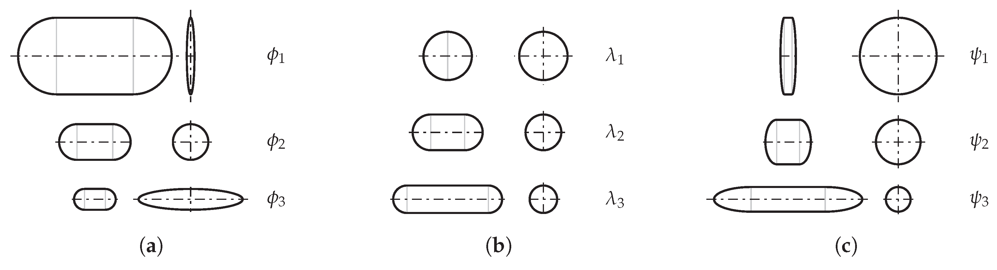
In contrast to most of the previous studies on hydrogen storage, which discuss a dimensioning on particular aircraft geometries, our approach is a more fundamental one: here, the tank design is evaluated over a wide range of the dimensionless parameters
,
and
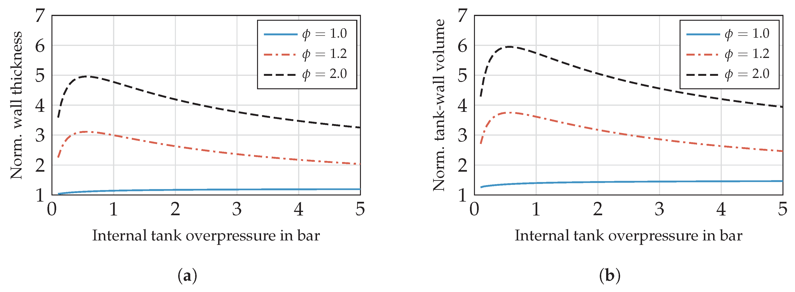
to draw general conclusions on the effect of shapes of tanks. With regard to the significant influence of
on the tank-wall volume (as seen in
Figure 7b), this parameter is varied between 0.5 and 1.5. Furthermore, the parameter
is considered within a range of
. Finally, the parameter
completes the set.
3.1.1. Single Tank
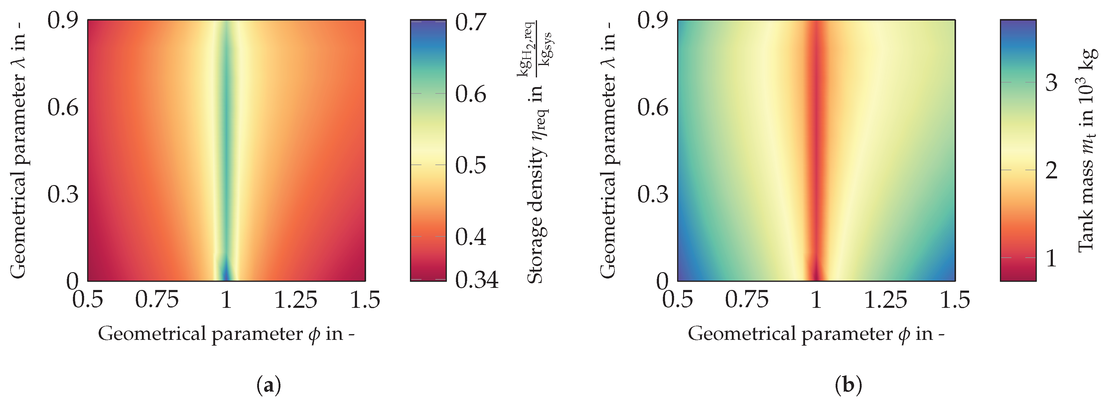
Proceeding with the evaluation of this study for a single tank solution,
Figure 13a shows the storage density
against
and
.
In total, a range in
from 0.34 up to 0.7 is covered, which means that the required hydrogen mass has a maximum share of the total system mass of nearly 70%. This value applies for a spherical tank showing a considerable advantage in wall volume. As indicated in
Section 2.2.4, cylindrical shells (
) exhibit superior storage densities compared to elliptical shapes. The former provide values for
above 0.6 for the complete range of
. For slightly un-round shells, the storage density decreases remarkably. Along the parameter
, the sensitivity on the storage density is significantly smaller.
A qualitatively similar characteristic is shown in
Figure 13b, which plots the tank mass, including insulation and wall mass, against the geometrical parameter
and
. Cylindrical shells offer a tank weight of about
kg, which rises significantly up to
kg for elliptical shells. The gradients from cylindrical to elliptical shells, as well as for increasing shell length behave similar to the observation in the previous paragraph. These sensitivities of the particular geometric parameters are investigated further in the next sections.
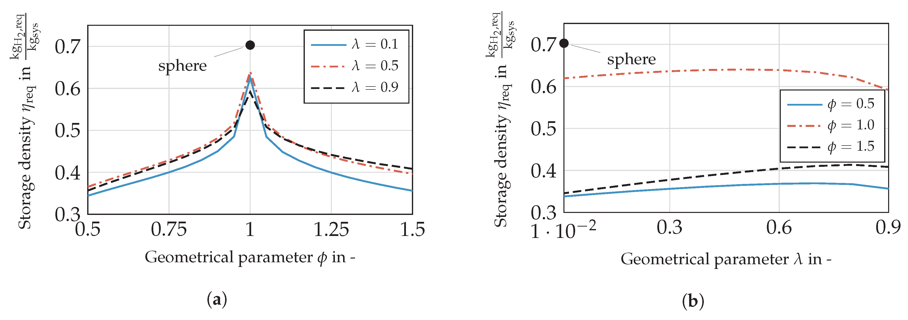
Dependency of on ϕ
Figure 14a shows the storage density in dependence of
for a selection of
. For comparison, the sphere is added, which shows a discontinuity in tank-wall thickness and therefore in storage density (see Equation (
1)). Changing the parameter
diminishes
up to 23%. Slightly elliptical shells (
= 1.2) show a significant higher tank-wall mass compared to cylindrical ones (as seen in
Figure 7). As a result, the wall thickness is highly responsible for this significant gradient. Increasing the un-roundness further the sensitivity on
drops, which is also referable to the wall mass. Towards a greater un-roundness in general, the tanks are geometrical similar for
and
. Differences in storage density are referable to the change rates in the wetted area of the gaseous and liquid hydrogen dependent on the filling level. Consequently, the pressure fluctuations obtain various temporal progresses leading to a different thermal design.
Dependency of on λ
Figure 14b shows the storage density against
for exemplary values of
. In contrast to the sensitivity on
, the parameter
shows significantly less impact on
. Starting from a cylindrical shell, the storage density differs by 10% over the range investigated, for
by
, and
exhibits a deviation of
with regard to the maximum.
For a cylindrical shell (), the optimum design lies within a flat maximum at . While increasing the un-roundness, the maximum shifts toward () and (), respectively. Picking up the motivation of this study, a particular range of is preferable, if the overall mass is the parameter to minimise. Although cylindrical shells are the most advantageous design option in terms of mass, the designs should feature a certain overall tank length.
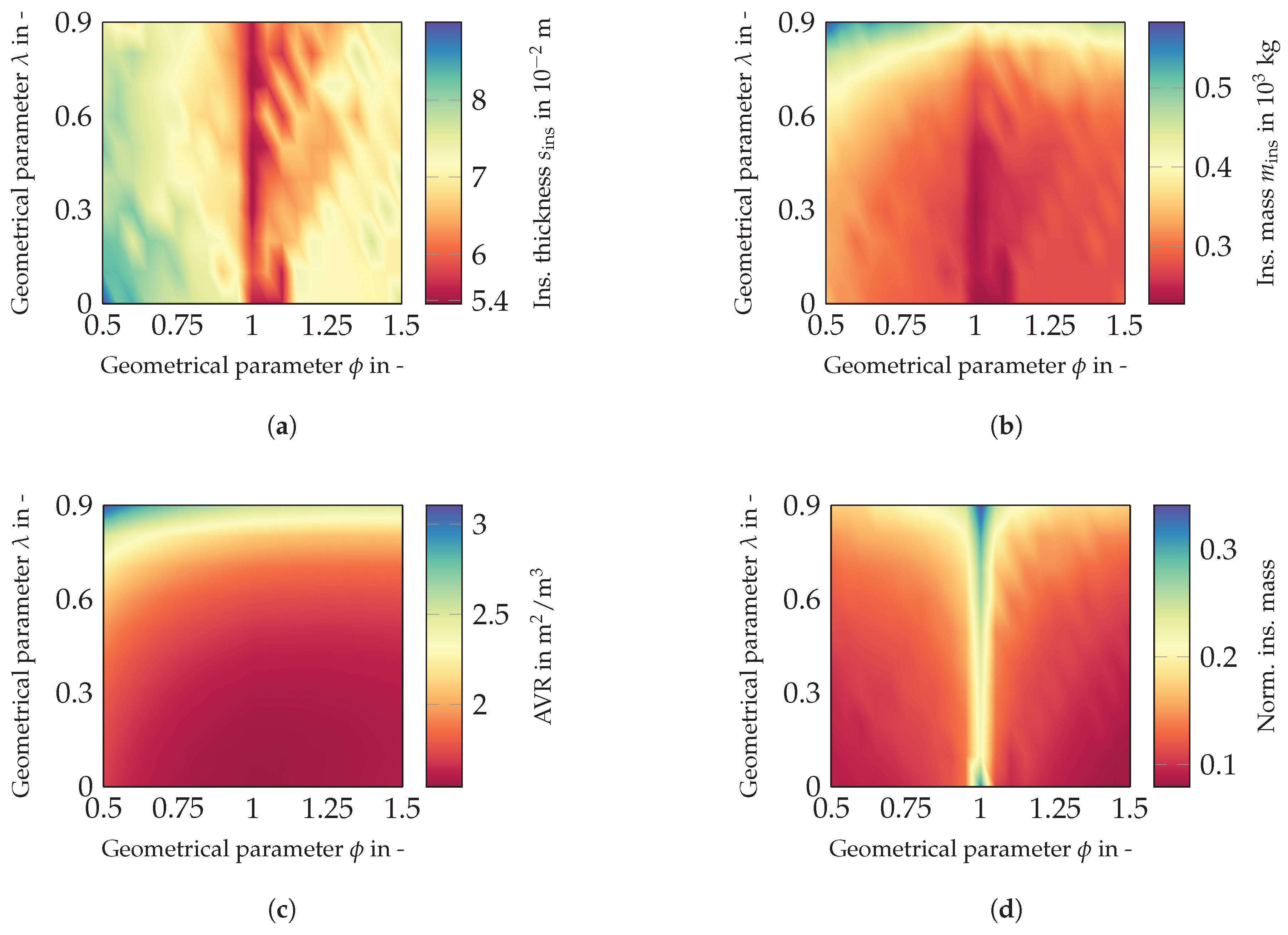
Considering additionally
Figure 15, it can be seen that designs with low lambda allow one to decrease the insulation mass that is needed (
Figure 15b). This occurs despite that the tank diameter increases for more compact tanks, resulting in thicker walls. Although, longer tanks (
) provide slight differences in insulation thickness according to
Figure 15a. Still, the insulation mass is far greater compared to compact tanks, because of the considerable disadvantage in surface-area-to-volume ratio. Consequently, the impacts of insulation and wall mass possess opposite signs and lead to a lower sensitivity on
compared to
.
Dependency of Geometric Parameters on
Larger insulation thicknesses can be observed for designs with decreasing
and increasing un-roundness. Since designs of less
provide greater wall thicknesses resulting from increased diameters (see
Figure 4), the sensitivity on the overall mass is considerably high. Allowing a certain amount of venting, the wall mass would rise remarkable to the rise in volume. Furthermore, the density of the wall material (
) exceeds the density of the insulations material (
) by two orders of magnitude. The point where the insulation thickness is the main driver in storage density change lies towards thicker insulations rather than for designs providing smaller tank diameters. The same applies for designs with a considerable un-roundness.
The insulation mass depends directly on the AVR (see
Figure 15b,c). The overall change in AVR is greater than change in
, so that the absolute insulation mass is in favour of the AVR. Nonetheless, the tank mass is mainly driven by the wall mass as shown in
Figure 15d. This is because, on the one hand, the insulation mass only amounts to 10%–35% of the tank mass. On the other hand, the qualitative characteristic of the normalised insulation mass is similar to the absolute insulation mass, since less insulation mass comes along with smaller shares of the total mass, but mainly driven by the tank-wall mass.
Furthermore, compact geometries providing a superior AVR do not represent the best options in terms of storage density (see
Figure 15c). With regard to their comparatively thick walls resulting from increased diameter, they offer considerably lower storage densities. From this study, tank designs with
between 0.6 and 0.8 are suggested in order to minimise the tank mass compared to the required fuel mass. The spherical design marks an exception according to a less thick wall and offers the highest storage density. Generally, cylindrical shells show their advantage compared to elliptical ones.
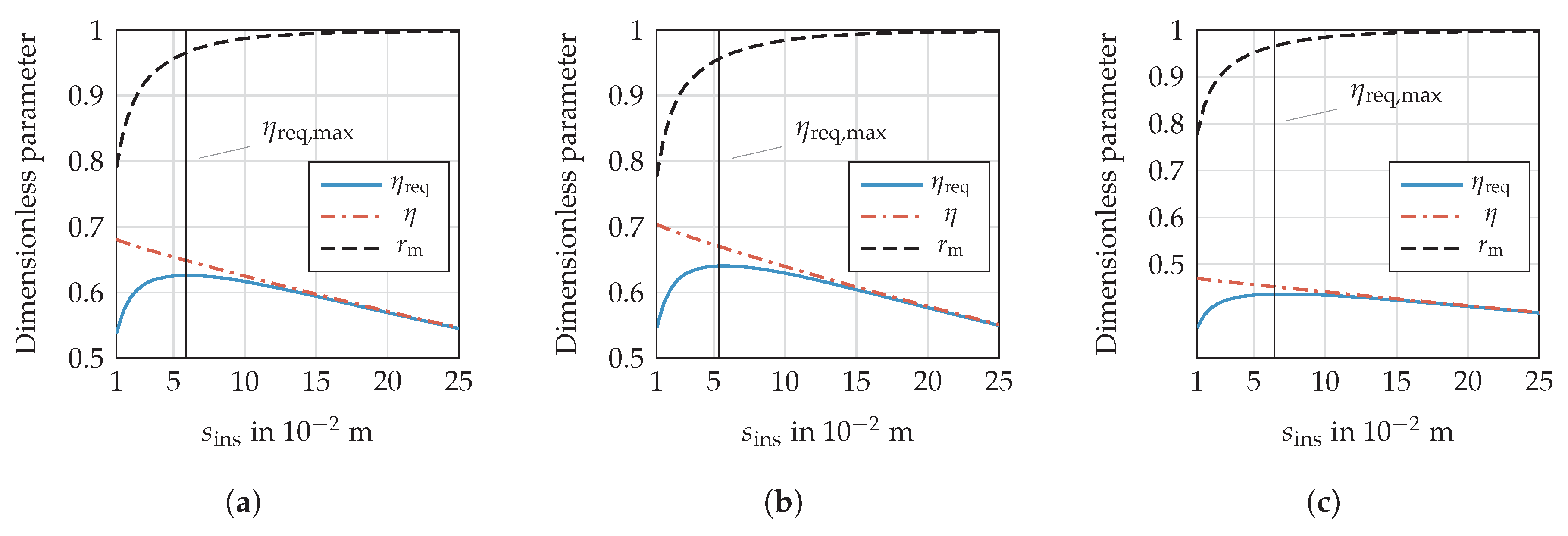
Dependency of on Storage Density and Venting
As the top-down approach discussed the results of the parameter study only, a brief, more in depth view shows the dependency of the insulation thickness on the storage density with an example.
Figure 16 illustrates
,
and
over a certain range of the insulation thickness
for selected parameters.
Whenever fuel is vented, the ratio of fuel mass and total mass (
) is higher than
(storage density), because the total hydrogen mass
exceeds the required fuel mass
by the amount of
. Furthermore, maximising the storage density is not essentially associated with
kg, if the boundary conditions basically allow a certain amount of venting. A share in the order of 1–5% of the vented losses in the total hydrogen mass leads to an optimum design regarding the storage density. As indicated in
Figure 16, the curve is flat around the maximum characterises
, which offers some scope in designing the insulation system. To illustrate this behaviour by some examples,
Figure 16 shows storage densities as a function of the insulation thickness for three parameter sets. The plots in
Figure 16a,b differ in the value of
, whereas
Figure 16c shows an increased
, but with the same
as the plot in
Figure 16b.
Especially for greater , the maximum becomes even flatter, so that the tolerance in the outer design loop ought to be significantly less. Nonetheless, proceeding from the maximum, the vented hydrogen mass rises significantly less towards thicker than thinner insulations. Consequently, highly under-estimated heat leakage might result in considerable boil-off losses, which decrease the available fuel mass, as well, if the tank is designed close to this critical gradient.
Interim Conclusion
To sum up, introducing materials for the mechanical design superior in density and strength in cryogenic environments promises great enhancement in tank weight due to noticeably high density and shares on the overall tank weight. Especially compact designs will gain the most benefit by improving the tank-wall material. Otherwise, longer tanks possess a greater share of the insulation mass in overall tank weight. Cylinders offer a comparable high share of approximately 30% in insulation mass, because the wall thickness is less compared to elliptical shells. The latter otherwise show shares between 10% and 20%. Improving the insulation system would lead to a considerable increase in for those geometries.
3.1.2. Multiple Tanks
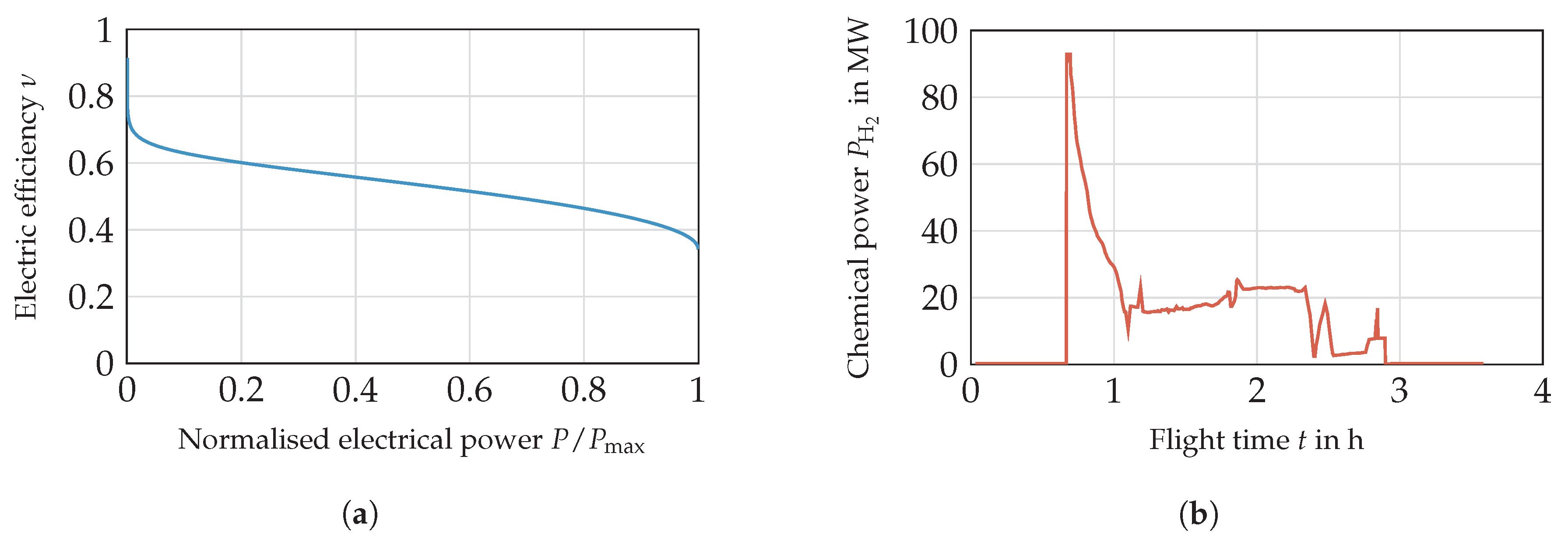
For geometrically-similar designs, a decrease in volume correlates with an increase in AVR in general. Therefore, a higher share of insulation mass on tank mass is expected. A volume variation is performed to investigate this effect. The power profile (see
Figure 11b) is multiplied by the factor
with
n = 0, 1, …, 4. For constant
n, each tank stores the same amount of energy, and the fuel is withdrawn equally. Consequently, the ratio between volume and outlet mass-flow remains constant. For assessing the impact of multiple tanks, the storage density
of the single tank (
) in the previous section can directly be compared to the multiple tank solution.
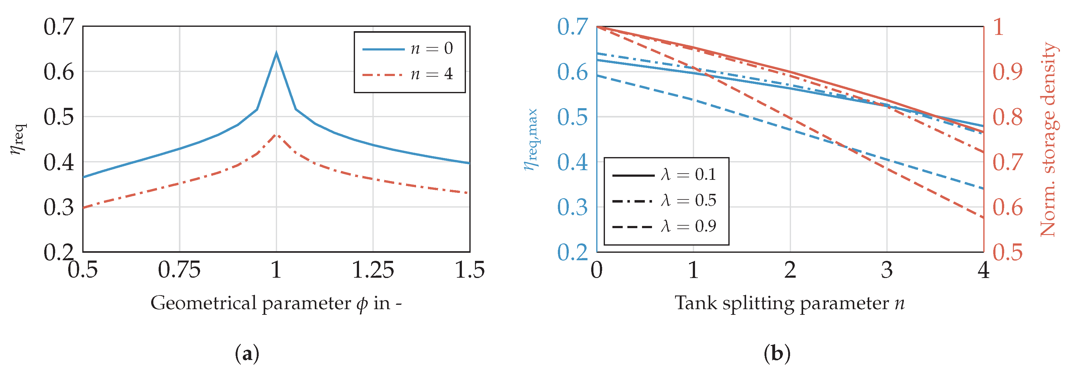
Figure 17 addresses the comparison of the single and multiple tank solution with regard to
.
Figure 17a plots the storage density against
. The loss in storage density is highest for cylindrical shells when storing the fuel in various tanks; this holds as well relatively. Since the reduction in tank-wall mass is considerable less compared to elliptical tanks, this effect does not compensate the disadvantage along with increasing AVR and accordingly in insulation mass. Nevertheless,
is still the favourable option. The density is lower at all
for the split tank version, because the AVR gains increasingly more impact when reducing the overall tank size. Therefore, designs providing a higher AVR in general suffer the most with regard to the storage density (
). This trend is more clearly shown in
Figure 17b, where the absolute maximum storage density and the change in maximum storage density normalised on
are plotted and evaluated for different
and
. The advantage of longitudinal tanks compared to compact designs is outweighed by the disadvantages associated with increasing
n. While increasingly compact designs are affected less by a tank splitting, the optimal value for
shifts towards zero. Although the design with
and
shows less storage density than the tank with
, it provides the smallest change rate, leading to a more competitive design for increasingly smaller tanks.
Splitting or rather reducing the tank size decreases the storage density over the whole range of the screened parameters. Further investigations appear to be thinkable against the background that multiple tank solutions are feasible with regard to various operating strategies. For example, a different withdrawal of the fuel might be advantageous in terms of tank insulation design, balancing the filling or the pressure levels, can be suitable as well. Though these hypotheses are not part of the present study, this should trigger further investigations.
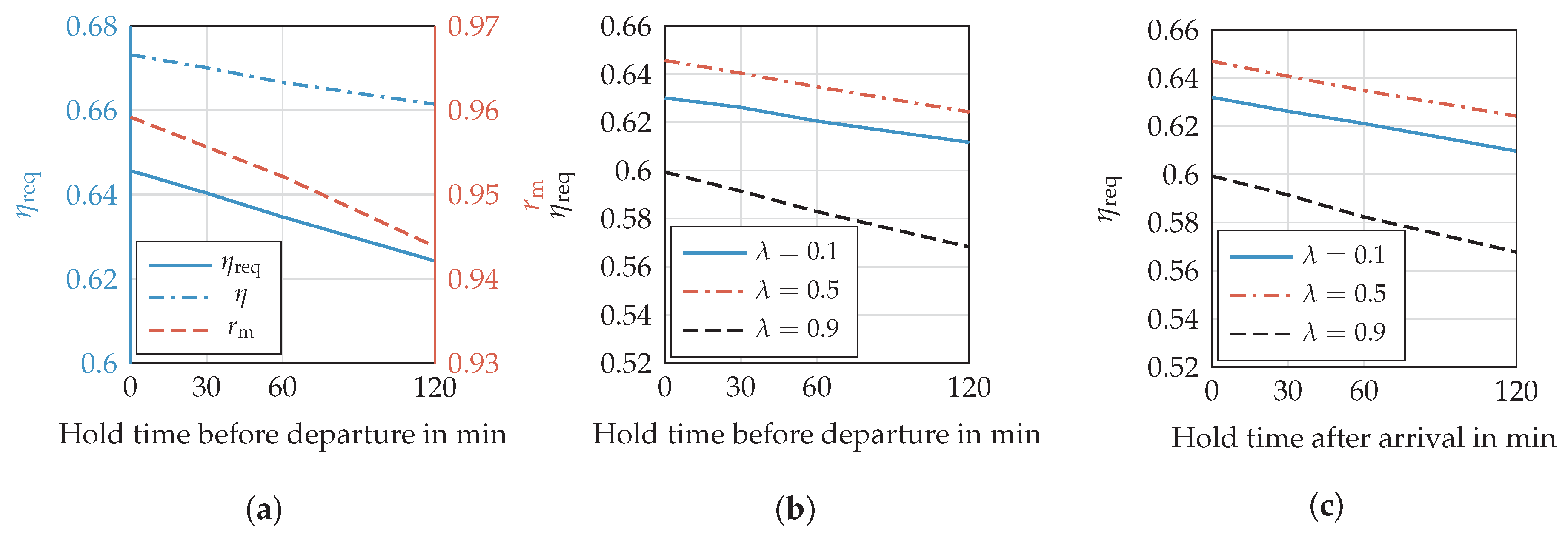
3.2. Hold Time
Since the pressure development inside the tank depends on the heat input, reducing the time on the ground appears to be desirable. For this reason, the impact of the hold time before departure and after arrival is investigated. Commencing with the time period before the flight,
Figure 18a shows
,
and
against various times.
The curves drop approximately linearly over the time investigated. With longer hold times, decreases from 95.9%–94.4%. Therefore, a rising amount of venting is accepted as opposed to a further increase in insulation thickness, in order to maximise the storage density. Since more fuel mass is stored, decreases as well. Combining and , the storage density decreases from 0.648–0.623 .
Figure 18b,c plots
against the hold time before departure and after arrival, respectively. The design with
shows the most significant drop in storage density, because it provides a comparatively high AVR. The other two curves behave equally, featuring a similar gradient. In addition, the hold time after arrival affects the storage density similar to the time before departure. Only the curve for
shows a slightly higher gradient. Since the tank is almost empty, the vapour mass fraction is significantly greater than provided by a refuelled tank. The derivation
(see Equation (
6)) is less for gaseous hydrogen, meaning a smaller amount of energy is required for a certain pressure rise compared to liquid.
This evaluation shows that reducing the hold time leads to less tank and fuel weight. Beside from an exclusive aircraft-related tank design, improving the turn-around time on ground is additionally desirable from this perspective.
3.3. Comparison to Kerosene Tanks
To put the presented results in context, the liquid hydrogen tanks are compared to kerosene tanks in terms of energy density and mass. Based on the presented results, an exemplary cylindrical hydrogen tank () can achieve a storage density of around 0.64. This corresponds to a gravimetric energy density of approximately 21 kWh/kg, which is significantly above 8.9 kWh/kg obtained by kerosene tanks. Although the tank reduces the effective energy density of hydrogen stronger compared to kerosene tanks (), the storage density is still 2.35-times higher. Besides the advantage in gravimetric density of hydrogen, the fuel savings by applying a fuel cell must be taken into account, as well. According to the mission profile in this study, the required hydrogen mass of 1912 kg is only 28% of the required kerosene mass, which amounts to 6890 kg. Consequently, the mass of the storage system including mass of kerosene (9187 kg) is nearly three-times the mass of the system (2988 kg). Although further requirements, such as maintaining cryogenic temperatures inside the tank, safety periphery and heat exchangers, are not covered here, tanks are highly competitive with kerosene tanks. If future materials are applied, the gravimetric energy density improves further.
Comparing the densities of liquid hydrogen and kerosene, the volume of is 11.4-times the volume of kerosene for the same mass. Applying the fuel mass, which is required for the exemplary mission, the factor is reduced to 3.34. Here, a mean density of 67.3 kg/ for hydrogen is chosen considering the gas fraction available for venting. The higher gravimetric energy density and the efficient fuel cell reduce the disadvantage in required hydrogen volume significantly. Although the volume is still tripled compared to kerosene, this technical challenge is manageable while introducing new airframe concepts.
4. Conclusions
In this study, a design tool for cryogenic hydrogen tanks is presented. Analysis of the sensitivity of the storage density shows the importance of using specific design missions for tank design and considering the hydrogen mass required for venting. Therefore, cryogenic hydrogen tanks ought to be tailored to a specific application, including new aircraft designs, as well as flight missions. This applies, because the insulation design depends on the overall mission profile. Additionally, the tank weight has a considerable share of the fuel weight.
Finding a universal solution in overall tank design is more challenging compared to kerosene tanks, because of the insulation design, which is influenced by numerous factors. This might result in over-sizing the insulation system for some applications. Therefore, an important aspect for future research is the investigation of tank structure integration into the airframe to reduce the disadvantage in unified thermal systems and increasing the energy density. Nonetheless, cryogenic hydrogen storage and a fuel cell-supplied propulsion system appear to be superior to the conventional system with regard to mass that has to be considered for storage. The disadvantage of liquid hydrogen compared to kerosene with regard to volume ought to be investigated in the context of the whole aircraft design. Although the integration of hydrogen tanks into common aircraft appears to be challenging or even inappropriate, future aircraft will be designed to accommodate new storage technologies. For this reason, further investigations covering the whole propulsion system are highly suggested under consideration of new design approaches.

 ,
, 


