Article

Super Capacitor Energy Storage Based MMC for Energy Harvesting in Mine Hoist Application

1
School of Electrical Engineering, Beijing Jiaotong University, Beijing 100044, China
2
Tianshui Electric Drive Research Institute Co. LTD, Tianshui 741020, China
*
Author to whom correspondence should be addressed.
Energies 2017, 10(9), 1428; https://doi.org/10.3390/en10091428
Submission received: 23 August 2017 / Revised: 10 September 2017 / Accepted: 13 September 2017 / Published: 17 September 2017
(This article belongs to the Special Issue Decentralised Energy Supply Systems)

Abstract

:
This paper proposes a super capacitor energy storage-based modular multilevel converter (SCES-MMC) for mine hoist application. Different from the conventional MMCs, the sub-modules employ distributed super capacitor banks, which are designed to absorb the regenerative energy of mine hoist and released in the traction condition, so as to improve energy utilization efficiency. The key control technologies are introduced in detail, followed by analysis of the configuration and operation principles. The feasibility of the proposed SCES-MMC topology and the control theory are also verified. Simulation results show that SCES-MMC can adapt to the variable frequency speed regulation of the motor drive, which shows good application prospects in the future for medium- and high-voltage mine hoist systems.

1. Introduction

The mine hoist conveyor is typically one of the largest consumers of electric power, besides of the excavator systems, of all equipment in the mining industry. As the only inoue-to-downhole access, the output performance of mine hoist electric transmission systems may not only play key roles in economical mine production, but may also affect equipment and personal safety [1,2]. In view of the large power rating requirements for mine hoist electric transmission systems, medium-voltage source converters (VSC) have increasingly gained importance due to their high power density, excellent efficiency, and high reliability [3,4,5]. For the last two decades, three-level neutral-point-clamped (NPC) VSCs have been the standard solution in the medium-voltage range for industrial applications [6,7]. Since the regenerative energy in an electric mine hoister and excavator may be as high as 60 percent of the motoring power [8,9], active front-end rectifiers (AFE) are usually adopted to feed the regenerative energy back into the power distribution grid in order for it not to be wasted. However, the practical constraints in the controller bandwidth may place restrictions on the system’s regenerative power handling. Therefore, protective circuits, such as DC choppers and crowbars, are usually added to the system for suppressing the DC bus over-voltage during regeneration [10].
Compared with NPC-VSC, modular multilevel converter (MMC) provides advantages such as high modularity, lower switching efficiency, high efficiency, better output voltage performance, etc. Thus, in addition to its successful commercial implementation in high voltage direct current (HVDC) transmission projects [11,12,13], it also shows good application prospects in fields such as power quality control [14,15]. However, AC drive-based MMCs are only suitable for industrial fans, pumps and other applications of small speed range close to the rated value. In order to solve the low-frequency torque ripple issues of conventional MMC motor drive systems, many scholars have carried out extensive research and proposed control strategies for common mode voltage/current multi-component injection and pulse optimization [16,17,18,19]. However, the above method does not fundamentally eliminate the limitations of MMC variable frequency-speed regulation control. On the other hand, domestic mine accidents have been frequent in recent years. If the high-voltage converter could continue to operate for a short time under outage conditions, the reliability of the mine hoist equipment would be significantly improved. In addition, when the mine hoist is braking, the electric transmission system will be in the generation condition, and the regenerating energy will charge the DC bus capacitor. An energy storage-enabled MMC seems an ideal solution for the abovementioned issues, since the super capacitors show better power density and a longer service life compared to traditional batteries. Thus, the super capacitor energy storage based MMC (SCES-MMC) is more suitable for mine hoist application. However, published technical papers focus mainly on battery energy storage system (BESS)-based MMCs [20,21]. In view of the above issues, this paper adopts the SCES-MMC for energy-harvesting applications. The super capacitor banks within the SCES-MMC operates as a power source to ensure the mine hoist keeps working for a short time when power failures occur unexpectedly. As a result, the safety of the mine hoist equipment can be significantly improved to avoid mine accidents. In addition, when the mine hoist is braking, the regenerative energy is quickly transferred to the SCES to avoid DC bus overvoltage.
This paper is organized as follows. Section 2 presents the structural characteristics and operation principles of SCES-MMC topology. In Section 3, the system control strategies including motor frequency controls and state of charge (SOC) balancing controls are explored in detail. To validate the feasibilities and effectiveness of the proposed topology and theory, extensive simulation results are demonstrated in Section 4. Finally, Section 5 reports the main conclusions.

2. Topology and Operation Principles

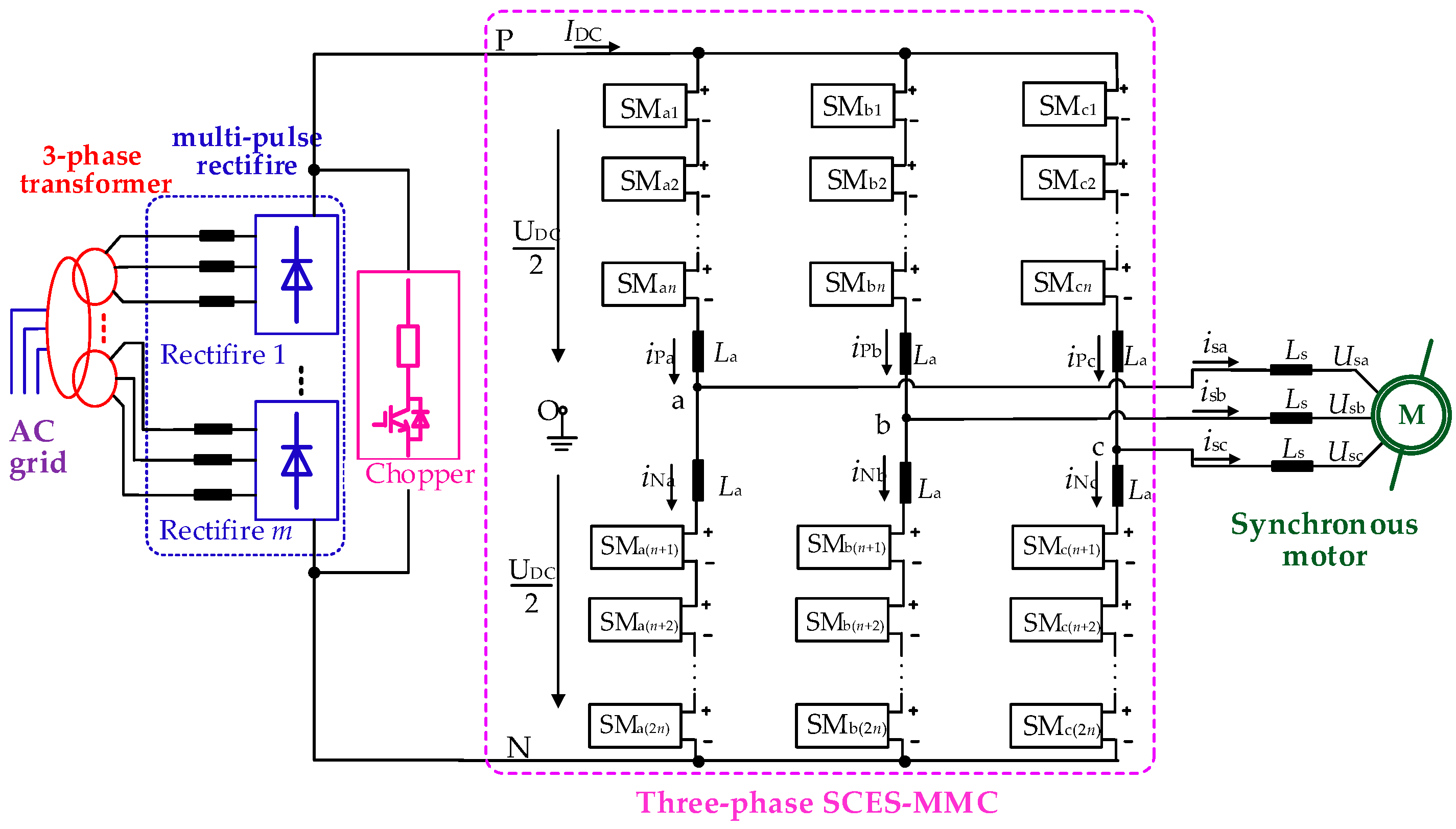
2.1. Topology Analysis

A typical topology for three-phase SCES-MMC is shown in Figure 1, where Ls is the output equivalent AC inductance, o is the neutral point of reference potential between the positive P and negative N of the DC bus. The SCES-MMC is three-phase balanced, and its phase-leg consists of 2n sub-modules SMjk (phase j =a, b, c, SMs number k = 1, 2, …, 2n) and leg inductance La. Figure 1b shows the basic building blocks-SCES-SM, which consists of two IGBTs (T1, T2), two anti-parallel diodes (D1, D2), a capacitor CSM, a super capacitor bank interface circuit.
Figure 2 demonstrates three widely-applied topologies for SCES-SM interface circuits: direct connection, bidirectional buck/boost converter and dual active bridge converter. The main difference between the latter two is the isolating transformer. To simplify the analysis, Figure 2a is selected as the SCES-SM interface circuit, but this does not affect the correctness of the theory. Additionally, the distributed super capacitors CSC results in an SCES-MMC with a highly modular structure and redundant capability, which further improves the reliability of the SCES-MMC for mine hoist applications. What is more, the circulating energy of SCES-MMC is exchanged between phase-legs through the common DC bus. Therefore, the SCES-SMs’ state of charge (SOC) may also be applied for system controls.

2.2. Operation Principles of SCES-MMC

The switching states of the SCES-SM are shown in Table 1, and the output voltage of SCES-SM is switched between zero and USC by controlling T1 and T2, where USC is the DC voltage of the SCES-SM. At the same time, SOC control of the corresponding super capacitor banks (SCBs) may also be implemented in this process.
According to the reference direction shown in Figure 1, AC current of phase-j during normal operation is expressed as
i P j = 1 3 I DC + 1 2 i s j + i Z j
i N j = 1 3 I DC 1 2 i s j + i Z j
i s j = i P j i N j
i C j = 1 3 I DC + i Z j
where iPj and iNj are the upper and lower arm currents, respectively; IDC is the DC bus current. The arm current flows through both the upper and lower legs consist of half of the AC output current isj and the common-mode current iCj, which consists of the DC component IDC/3 and the circulating component iZj. The former refers to the active power for charging and discharging the SM capacitors, while the latter indicates the reactive power causing the SM capacitor voltage ripples. Similarly, the resulting AC and DC voltages are determined by
u P j = U DC 2 u j L a d i P j d t R a i P j
u N j = U DC 2 + u j L a d i N j d t R a i N j
u j = u N j u P j 2 L a 2 d i j d t R a 2 i j
U DC = u P j + u N j + 2 L a d i C j d t + 2 R a i C j
where uj is the AC output phase voltage, UDC is the rated DC bus voltage, Ra is the equivalent series arm resistor, and uPj and uNj denote the upper and lower arm voltages, respectively.

2.3. Power Flow Analysis

Figure 3 illustrates the power flow modes, where PSCES refers to the power absorbed/released by SCES, the load side power Pload is represented by Ptrac when under traction conditions, or by Preg when under regeneration conditions. The fundamental power exchange relation is as follows
P Load = P dc + P SCES
With regard to bidirectional power flow characteristics, SCES-SM charging/discharging is realized through different operation modes. The two basic operation modes in SCES-MMC are defined as follows.
  • Normal operation mode: |PLoad| > |Pdc|
    Mode (a): PLoad = Pdc, PSCES = 0;
    Mode (b): Pdc > 0, PSCES > 0 (discharging), Ptrac > 0 (traction condition);
    Mode (c): Pdc < 0, PSCES < 0 (charging), Preg> 0 (regeneration condition);
  • Fault operation mode: Pdc = 0
    Mode (d): PLoad = PSCES.
In mode (a), SCES does not participate in the work. As a result, the operation principles of SCES-MMC are similar to the conventional MMCs. Load side power is fed exclusively from the DC bus of the SCES-MMC. Notably, when the mine hoist motor is braking, the regenerative energy maybe consumed on the DC bus due to the uncontrolled rectifier, as shown in Figure 3a.
In mode (b), the load side motor is under traction conditions, and the SCES functions as the DC source; thus, SCBs discharge to provide part of the AC load power, as shown in Figure 3b.
In mode (c), the load side motor is under regenerative conditions, and the SCES absorbs part of the regenerative power from the mine hoist motor. However, extra regenerative power is still consumed on the DC bus.
In contrast to conventional MMCs, when power outage faults occur, SCES will play the role of sole DC source, and feed the AC side load under similar control strategies as those shown in Figure 3d; thus, the mine hoist motor system is capable of continuing to work for a short time. This is a major advantage of SCES-MMC in terms of enhancing system reliability.

3. System Control Strategies

The SCES-MMC operates differently from regular MMCs. Since the SCBs within each SCES-SM are able to act as the DC source for supplying the AC load, the power will be delivered not only from the DC bus but also the SCES. Therefore, the SCES-MMC control strategy, when applied to the mine hoist motor drive system, includes two main parts, namely, motor variable frequency speed regulation (VFSR) control and SOC control.

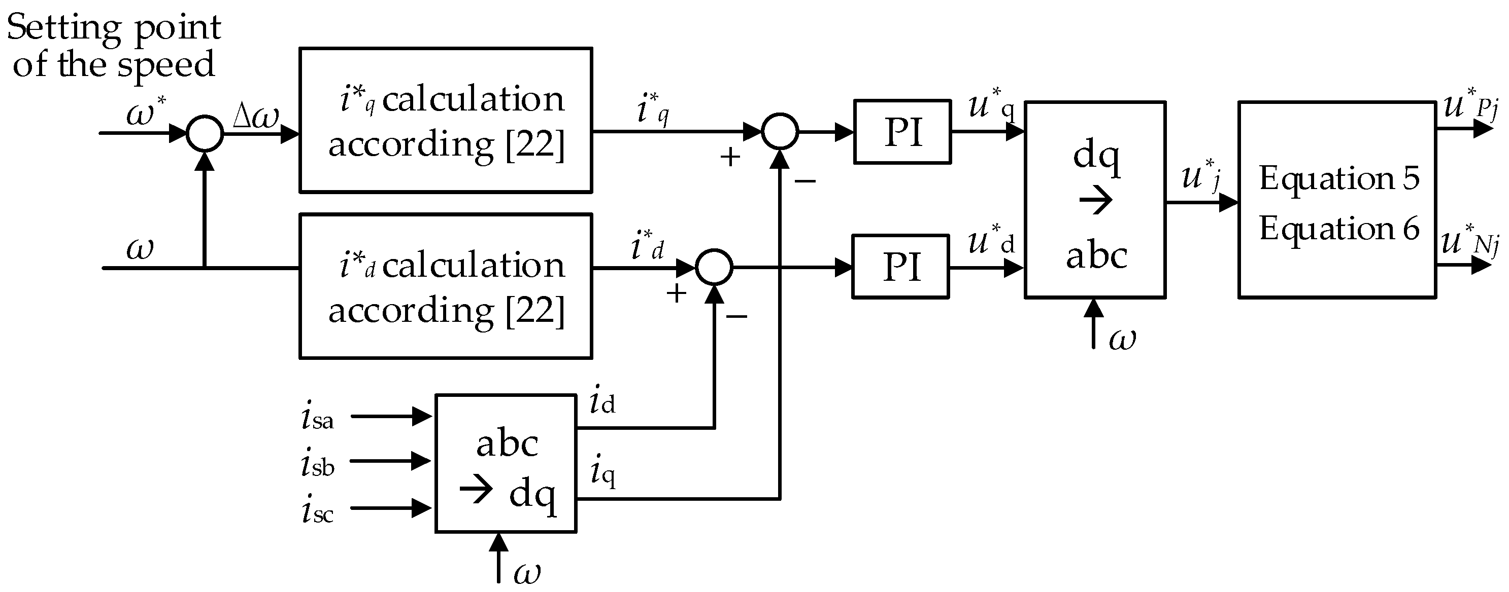
3.1. Variable Frequency Speed Control
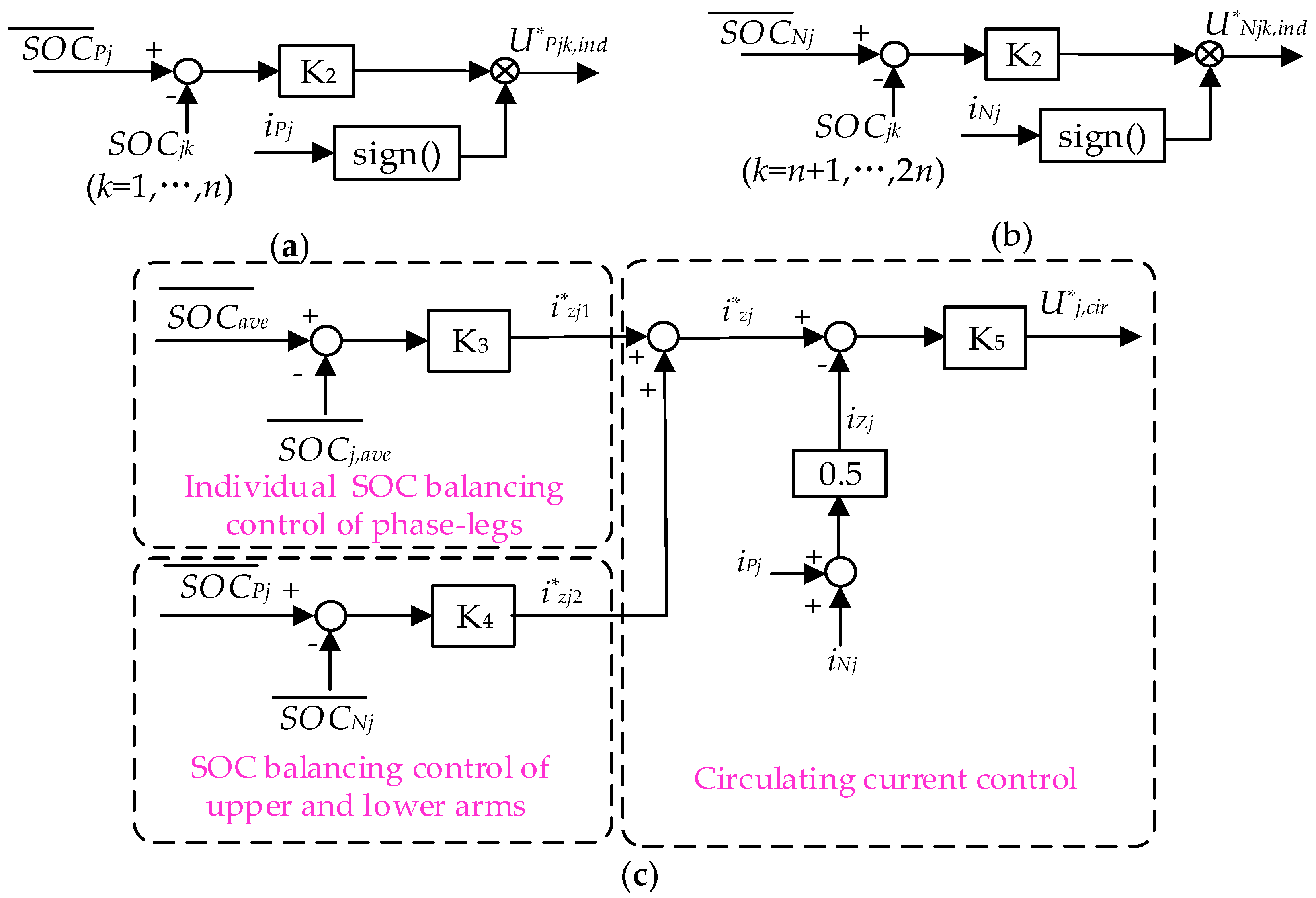
The typical operating states of the mine hoist include acceleration, uniform speed, and deceleration; thus, speed regulation is one of the main control targets. Based on the active flux observer (AFO)-based variable frequency speed regulation control proposed in [22,23], the SCES-MMC VFSR control strategy proposed in this paper is shown in Figure 4, where ω* and ω are the reference mine hoist rotor speed and the observed rotor speed obtained by the active flux observer (AFO) proposed in [22,23], respectively. The reference current i*q, i*d is calculated according to the mathematical model of synchronous motors, as proposed in [22]. Proportional integral regulator PI refers to the current loop controller. Consequently, the upper- and lower-arm voltages u P j and u N j are calculated based on Equations (5) and (6).

3.2. SOC Control

SOC control is one of the main differences from conventional MMCs. It is essential to control the circulating current of SCES-MMC to maximize the efficiency of the SOC controls. According to the configuration features, The SOC control structure of SCES-MMC generally includes SOC control of upper/lower arm sub-modules and SOC balancing control of phase-legs, as shown in Figure 5, where K2 to K5 refer to closed-loop controllers such as PI controllers.
Figure 5a,b shows the block diagram of individual SOC balancing controls, so as to make the SCES-SM SCBs SOC on the same leg equal to its corresponding average arm SOC ( S O C ¯ P j , S O C ¯ N j ). sign() denotes the signum function, and the average arm SOC S O C ¯ P j , S O C ¯ N j are expressed as follows:
S O C ¯ P j = 1 n k = 1 n S O C j k
S O C ¯ N j = 1 n k = n + 1 2 n S O C j k
The arm SOC balancing control aims to eliminate the deviation between the average arm SOCs. Similarly, the SOC balancing control of the phase-legs aims to eliminate the deviation between the average SOC ( S O C ¯ j , a v e ) of each phase and the three-phase average SOC ( S O C ¯ a v e ). Therefore, S O C ¯ j , a v e and S O C ¯ a v e are given by:
S O C ¯ j , a v e = 1 2 n k = 1 2 n S O C j k
S O C ¯ a v e = 1 3 j = a c S O C ¯ j , a v e
The above SOC control is implemented by the control of the circulating current, and the reference circulating current i Z j is calculated from the outputs of the above two SOC balancing control i Z j 1 and i Z j 2 , as follows
i Z j = i Z j 1 + i Z j 2
The controller of the circulating current inner loop aims to make the actual circulating current izj equal to the reference current i Z j , and then to realize the SOC balancing control, with the reference voltage U j , c i r being the output of the controller.
In summary, system control structures for the SCES-MMC are shown as Figure 6, where the reference voltage of the phase arm is calculated as follows:
U P j k = u P j n + U P j k , i n d + U j , c i r + U D C n
U N j k = u N j n + U N j k , i n d + U j , c i r + U D C n

4. Verifications of SCES-MMC

To verify the feasibility of the proposed SCES-MMC mine hoist system and control strategies, a simulation model of a nine-level SCES-MMC was created, as shown in Figure 7. The multi-pulse rectifier and chopper cell are employed to supply the constant DC bus voltage UDC. The simulation model parameters of SCES-MMC are listed in Table 2, and the initial SOC value of the SCBs is 100%. The super capacitor parameter design and selection method are similar to [24], and the modulation method adopted in this simulation is carrier phase-shifted sinusoidal pulse-width-modulation, combined with the third harmonic injection method of [25]. In addition, assuming that the synchronous motor reaches the rated speed at 0.6 s and starts decelerating at 0.9 s, the SCES-MMC output performance is shown in Figure 8.
Figure 8a,b shows that the frequency of the voltage and the current will gradually rise to its rated value under variable frequency speed regulation control. The SCES-MMC comes to its steady state at 0.6 s, and then gradually decays when the system enters the deceleration condition at 0.9 s. From the speed characteristics of the synchronous motor shown in Figure 8c, it can be seen that, before 0.6 s, the SCBs begin to release energy when the motor speed is rising and the system SOC is decreasing, as shown in Figure 8d. Then, the motor speed starts to drop when the synchronous motor brakes at 0.9 s, and the regenerative power in this process will also help charge the SCB of each SCES-SM, hence its SOC will rise.
Due to the high capacitance of the SCBs, even if a large amount of energy is released/absorbed, there is no significant fluctuation in the sub-module capacitor voltage USM, as shown in Figure 8e,f.
Figure 9 illustrates the power distribution laws of the proposed SCES-MMC. From the above-mentioned analysis, it can be concluded that the SCBs in the SCES-MMC will be discharged to provide about 69% of the AC load power requirement. Thus, less DC power is required compared to those without super capacitor banks. Since SCES is involved in absorbing part of the regenerative power from the mine hoist motor, under regeneration conditions, the power dissipated in the SCES-MMC is also less than for conventional MMCs. This makes it possible to minimize the capacity requirements of the AC grid and energy loss of the mine hoist system.

5. Conclusions

A super capacitor energy storage-based modular multilevel converter (SCES-MMC) topology for mine hoist applications has been investigated in this paper. In contrast to conventional MMCs, the sub-modules employ distributed SCBs, which are designed to absorb the regenerative energy of the mine hoist, and release it under traction conditions. Due to the high power density of the super capacitor, the sub-modules’ capacitor voltage will not significantly fluctuate. The configuration and operation principles, together with control technologies were studied in detail. Moreover, the feasibility of the proposed SCES-MMC topology and the control theory were also verified. Simulation results show that SCES-MMC makes reasonable use of the energy of the system through the distributed SCBs, improving the energy utilization efficiency, and shows good application prospects in future medium-/high-voltage mine hoist systems.

Acknowledgments

The authors gratefully acknowledge technical support from the National Key Research and Development Program of China (Award Number: 2016YFE0131700) and the State Key Laboratory of Large Electric Drive System and Equipment Technology (Award Number: SKLLDJ042016005).

Author Contributions

Xiaofeng Yang contributed to the concept, undertook significant theory analysis, and wrote the paper. Piao Wen and Yao Xue helped perform the simulation with constructive discussions, Trillion Q. Zheng supplied guidance, and Youyun Wang provided the field testing parameters and edited the manuscript. All authors read and approved the manuscript.

Conflicts of Interest

The authors declare no conflicts of interest.

Abbreviations

The following abbreviations are used in this manuscript:
ACalternating current
DCdirect current
HVDChigh voltage direct current
VSCvoltage source converter
NPCneutral-point-clamped
AFEactive front end
SCESsuper capacitor energy storage
MMCmodular multilevel converter
SMsub-module
SCBsuper capacitor bank
SOCstate of charge
IGBTinsulated gate bipolar transistor
VFSRvariable frequency speed regulation

References

  1. Chen, H. Research and Application Based on Full Digital DC Speed Adjusting Device in Mine Hoist Automation System. In Proceedings of the International Symposium on Intelligence Information Processing and Trusted Computing, Huanggang, China, 28–29 October 2010; pp. 524–527. [Google Scholar]
  2. Ferreira, V.N.; Mendonça, G.A.; Rocha, A.V.; Resende, R.S.; Cardoso Filho, B.J. Medium voltage IGBT-based converters in mine hoist systems. In Proceedings of the IEEE Industry Applications Society Annual Meeting, Portland, OR, USA, 2–6 October 2016; pp. 1–8. [Google Scholar]
  3. Abu-Rub, H.; Holtz, J.; Rodriguez, J.; Ge, B. Medium-Voltage Multilevel Converters—State of the Art, Challenges, and Requirements in Industrial Applications. IEEE Trans. Ind. Electron. 2010, 57, 2581–2596. [Google Scholar] [CrossRef]
  4. Kouro, S.; Malinowski, M.; Gopakumar, K.; Pou, J.; Franquelo, L.G.; Bin, W.; Rodriguez, J.; Perez, M.A.; Leon, J.I. Recent Advances and Industrial Applications of Multilevel Converters. IEEE Trans. Ind. Electron. 2010, 57, 2553–2580. [Google Scholar] [CrossRef]
  5. Yang, X.; Li, J.; Wang, X.; Fan, W.; Zheng, T.Q. Circulating Current Model of Modular Multilevel Converter. In Proceedings of the Asia-Pacific Power and Energy Engineering Conference (APPEEC), Wuhan, China, 25–28 March 2011; pp. 1–6. [Google Scholar]
  6. Krug, D.; Malinowski, M.; Bernet, S. Design and comparison of medium voltage multi-level converters for industry applications. In Proceedings of the 39th IEEE Industry Applications Conference (IAS), Seattle, WA, USA, 3–7 October 2004; pp. 781–790. [Google Scholar]
  7. Asea Brown Boveri. ACS 6000 Medium Voltage AC Drives—Commissioning Manual; ABB Switzerland Ltd.: Zurich, Switzerland, 2004. [Google Scholar]
  8. Abdel-baqi, O.; Nasiri, A.; Miller, P. Dynamic Performance Improvement and Peak Power Limiting Using Ultracapacitor Storage System for Hydraulic Mining Shovels. IEEE Trans. Ind. Electron. 2015, 62, 3173–3181. [Google Scholar] [CrossRef]
  9. Parkhideh, B.; Mirzaee, H.; Bhattacharya, S. Supplementary Energy Storage and Hybrid Front-End Converters for High-Power Mobile Mining Equipment. IEEE Trans. Ind.Appl. 2013, 49, 1863–1872. [Google Scholar] [CrossRef]
  10. Parkhideh, B.; Bhattacharya, S.; Mazumdar, J.; Koellner, W. Utilization of Supplementary Energy Storage Systems in High Power Mining Converters. In Proceedings of the 2008 IEEE Industry Applications Society Annual Meeting, Edmonton, AB, Canada, 5–9 October 2008; pp. 1–7. [Google Scholar]
  11. Dorn, J.; Huang, H.; Retzmann, D. Novel Voltage-Sourced Converters for HVDC and FACTS Applications. In Proceedings of the CIGRE Symposium, Osaka, Japan, 1–4 November 2007; pp. 314–321. [Google Scholar]
  12. Yang, X.; Xue, Y.; Chen, B.; Lin, Z.; Mu, Y.; Zheng, T.Q.; Igarshi, S. Reverse blocking sub-module based modular multilevel converter with DC fault ride-through capability. In Proceedings of the IEEE Energy Conversion Congress and Exposition (ECCE), Milwaukee, WI, USA, 18–22 September 2016; pp. 1–7. [Google Scholar]
  13. Yang, X.; Xue, Y.; Chen, B.; Lin, Z.; Zheng, T.Q.; Li, Y. Novel modular multilevel converter against DC faults for HVDC applications. CSEE J. Power Energy Syst. 2017, 3, 140–149. [Google Scholar]
  14. Ma, F.; Xu, Q.; He, Z.; Tu, C.; Shuai, Z.; Luo, A.; Li, Y. A Railway Traction Power Conditioner Using Modular Multilevel Converter and Its Control Strategy for High-Speed Railway System. IEEE Trans. Transp. Electrif. 2016, 2, 96–109. [Google Scholar] [CrossRef]
  15. Yang, X.; Zheng, T.Q.; Lin, Z.; Tao, X.; You, X. Power Quality Controller Based on Hybrid Modular Multilevel Converter. In Proceedings of the the 21st IEEE International Symposium on Industrial Electronics (ISIE), Hangzhou, China, 28–30 May 2012; pp. 1997–2002. [Google Scholar]
  16. Hagiwara, M.; Akagi, H.; Nishimura, K. A Medium-Voltage Motor Drive with a Modular Multilevel PWM Inverter. IEEE Trans. Ind. Electron. 2010, 25, 1786–1799. [Google Scholar] [CrossRef]
  17. Li, B.; Zhou, S.; Xu, D.; Yang, R.; Xu, D.; Buccella, C.; Cecati, C. An Improved Circulating Current Injection Method for Modular Multilevel Converters in Variable-Speed Drives. IEEE Trans. Ind. Electron. 2016, 63, 7215–7225. [Google Scholar] [CrossRef]
  18. Antonopoulos, A.; Angquist, L.; Harnefors, L.; Nee, H. Optimal Selection of the Average Capacitor Voltage for Variable-Speed Drives With Modular Multilevel Converters. IEEE Trans. Ind. Electron. 2015, 30, 227–234. [Google Scholar] [CrossRef]
  19. Kolb, J.; Kammerer, F.; Gommeringer, M.; Braun, M. Cascaded Control System of the Modular Multilevel Converter for Feeding Variable-Speed Drives. IEEE Trans. Power Electron. 2015, 30, 349–357. [Google Scholar] [CrossRef]
  20. Vasiladiotis, M.; Rufer, A. A Modular Multiport Power Electronic Transformer with Integrated Split Battery Energy Storage for Versatile Ultrafast EV Charging Stations. IEEE Trans. Ind. Electron. 2015, 62, 3213–3222. [Google Scholar]
  21. Quraan, M.; Yeo, T.; Tricoli, P. Design and Control of Modular Multilevel Converters for Battery Electric Vehicles. IEEE Trans. Power Electron. 2016, 31, 507–517. [Google Scholar] [CrossRef]
  22. Agarlita, S.; Coman, C.; Andreescu, G.; Boldea, I. Stable V/f control system with controlled power factor angle for permanent magnet synchronous motor drives. IET Electron. Power Appl. 2013, 7, 278–286. [Google Scholar] [CrossRef]
  23. Boldea, I.; Paicu, M.C.; Andreescu, G. Active Flux Concept for Motion-Sensorless Unified AC Drives. IEEE Trans. Power Electron. 2008, 23, 2612–2618. [Google Scholar] [CrossRef]
  24. Sau, S.; Fernandes, B.G. Analysis and reduction of capacitor ripple current in modular multilevel converter for variable speed drives. In Proceedings of the European Conference on Power Electronics and Applications (EPE’16 ECCE Europe), Karlsruhe, Germany, 5–9 September 2016; pp. 1–10. [Google Scholar]
  25. Li, R.; Fletcher, J.E.; Williams, B.W. Influence of third harmonic injection on modular multilevel converter -based high-voltage direct current transmission systems. IET Gener. Transm. Distrib. 2016, 10, 2764–2770. [Google Scholar] [CrossRef] [Green Version]
Figure 1. Configuration of three-phase SCES-MMC and its sub-module: (a) Three-phase SCES-MMC topology; (b) SCES-SM.
Energies 10 01428 g001
Figure 2. Topology of SCES-SM interface circuit: (a) Direct connection (b) Bidirectional buck/boost converter (c) Dual active bridge converter.
Energies 10 01428 g002
Figure 3. Illustration of power flow: (a) Conventional VSC without SCES; (b) Traction (discharging) condition; (c) Regeneration (charging) condition; (d) Fault operation mode.
Energies 10 01428 g003
Figure 4. Block diagram of variable frequency speed control.
Energies 10 01428 g004
Figure 5. Block diagram of SOC control: (a) Individual SOC control (upper arm); (b) Individual SOC control (lower arm); (c) SOC balancing control.
Energies 10 01428 g005
Figure 6. Overview of system control structures for SCES-MMC.
Energies 10 01428 g006
Figure 7. Configuration of SCES-MMC simulation model.
Energies 10 01428 g007
Figure 8. Output performance of SCES-MMC: (a) AC output voltage; (b) AC output current; (c) Motor speed; (d) Average SOC of SCBs; (e) Voltage of the SCBsphase a; (f) Voltage of the SCBsphase b.
Energies 10 01428 g008
Figure 9. Power distributions.
Energies 10 01428 g009
Table 1. Switching states of SCES-SM.
ModeT1/D1T2/D2iSMOutput VoltageSOC
Charging0/10/0>0USCincreasing
Discharging1/00/0<0USCdecreasing
Bypass01>00maintaining
Bypass01<00maintaining
Table 2. Simulation parameters of SCES-MMC.
System ParametersValue
AC line-to-line voltage1.45 kV
DC link voltage3.6 kV
Rated power5.3 MW
Leg inductance5.0 mH
SM capacitor voltage0.45 kV
Super capacitor capacitance20 F
Rated speed52 rpm

