Article

Charge Equalization Controller Algorithm for Series-Connected Lithium-Ion Battery Storage Systems: Modeling and Applications

1
Department of Electrical Power Engineering, Universiti Tenaga Nasional, Kajang 43000, Malaysia
2
Department of Electrical & Electronic Engineering, University of Chittagong, Chittagong 4331, Bangladesh
3
Institute of Climate Change, Universiti Kebangsaan Malaysia, Bangi 43600, Selangor, Malaysia
4
Department of Electrical, Electronic and Systems Engineering, Universiti Kebangsaan Malaysia, Bangi 43600, Selangor, Malaysia
*
Author to whom correspondence should be addressed.
Energies 2017, 10(9), 1390; https://doi.org/10.3390/en10091390
Submission received: 21 August 2017 / Revised: 3 September 2017 / Accepted: 7 September 2017 / Published: 13 September 2017
(This article belongs to the Section D: Energy Storage and Application)

Abstract

:
This study aims to develop an accurate model of a charge equalization controller (CEC) that manages individual cell monitoring and equalizing by charging and discharging series-connected lithium-ion (Li-ion) battery cells. In this concept, an intelligent control algorithm is developed to activate bidirectional cell switches and control direct current (DC)–DC converter switches along with pulse width modulation (PWM) generation. Individual models of an electric vehicle (EV)-sustainable Li-ion battery, optimal power rating, a bidirectional flyback DC–DC converter, and charging and discharging controllers are integrated to develop a small-scale CEC model that can be implemented for 10 series-connected Li-ion battery cells. Results show that the charge equalization controller operates at 91% efficiency and performs well in equalizing both overdischarged and overcharged cells on time. Moreover, the outputs of the CEC model show that the desired balancing level occurs at 2% of state of charge difference and that all cells are operated within a normal range. The configuration, execution, control, power loss, cost, size, and efficiency of the developed CEC model are compared with those of existing controllers. The proposed model is proven suitable for high-tech storage systems toward the advancement of sustainable EV technologies and renewable source of applications.

1. Introduction

Sustainable energies and electric vehicles (EVs) have attracted increasing attention as an alternative to conventional energy systems because of their contributions to green global environment and fossil fuel demand reduction. Developing competent EVs with efficient energy management and storage systems is a great concern to automobile developers and researchers [1,2,3]. Among secondary batteries, lithium-ion (Li-ion) batteries are currently the best candidate in hybrid electric vehicle (HEV), plug-in hybrid electric vehicle (PHEV), and battery-powered electric vehicle (BEV) storage applications because of their high storage capability, high energy and power densities, low hysteresis, no memory effects, long life cycle duration, and high terminal voltage [1,4].
Li-ion batteries are applied for large-scale energy storage systems in EVs with a number of series-connected battery cells in a pack. Li-ion batteries provide high voltage and power in high specific energy and power with a low self-discharge rate to EV motors [5,6]. However, these batteries are affected by the imbalance voltage properties of battery cells because of changes in their physical characteristics after a few charge–discharge cycles. Imbalance voltage profiles may reduce the overall performance and durability of energy storage systems [7,8]. Overcharging might cause cell explosion, whereas overdischarging might damage the chemical properties and thus shorten the life of battery cells [9]. A battery management system is essential to protect Li-ion battery cells from overcharging and overdischarging [10].
A battery management system with individual cell monitoring and charge equalization could save battery cells from anomalies caused by overcharging and overdischarging and enhance the overall performance of an energy storage system to effectively power EVs [11,12]. Modeling of a charge equalization controller is an imperative concern that has the key rule to monitor cell conditions and equalize cell charges within a normal operating range.
Various studies and developments on passive and active charge equalization techniques have been carried out to equalize the charges of series-connected battery cells [12,13]. Resistor shunting or analog shunting as a passive charge equalization controller features a simple design and implementation, but suffers from heat and energy dissipation problems [12,13,14]. Active equalization controllers could be based on capacitors, inductors, transformers, and converters to transfer excess energy from an overcharged cell to other-cell/module/pack or to carry the equalization current to an overdischarged cell from other-cell/module/pack [12,13,15]. Capacitor-based charge equalization controllers are applied to shuttle excess energy via capacitors, which are easy to design; however, capacitors possess large current ripples and need long equalization times [16,17]. Equalization controllers based on inductors and transformers require short equalization times and feature a high speed and current; however, these controllers suffer from magnetizing loss, need a capacitor filter, and are expensive [18,19]. Flyback [20], resonant [21,22] and buck-boost [23,24] converter-based charge equalization controllers are efficient in EV applications with various topologies. These controllers demonstrate bidirectional balancing capabilities, fast equalization speed, high efficiency, and low stress, but they require complex control and design, and are costly [12,13,14,15,16,17,18,19,20,21,22,23,24,25]. All existing controllers sufficiently meet the present demand for battery cell equalization in EVs. However, they show disadvantages in terms of equalization time, power loss, heat management, cost, design, and voltage/current stress [12,13,25].
For protecting and fault detecting the battery with efficient charge equalization, the state of charge (SOC) and state of health (SOH) estimation is important in energy storage applications [26]. SOC and SOH estimation have proved challenging for developing and improving battery technologies because of changes in batteries’ electrochemical profile, variation of ambient and load conditions, etc. [27]. A number of studies have been accomplished to predict the SOC and SOH of battery by a variety of methods such as the model predictive control method [28], open circuit method [29], dynamic method [30], adaptive sliding mode observer method [31], spherical cubature particle filter method [32], particle swarm optimization method [33], Kalman filter method [34], data handling group method [35], relevance vectors and capacity degradation model [36], state space model [37] and others [38,39,40]. These different estimation methods have been applied as the service requirement and compatibility with the system, especially battery charge equalization, however, SOC and SOH estimation still have big challenges due to the internal and external factors of batteries.
With the progress of research and development aiming to minimize the deficiencies of existing charge equalization controllers, a model of charge equalization controller is proposed to diminish the problems related to equalization time, design and control complexity, and voltage/current stress. The controller is implemented to monitor and equalize the charge levels of series-connected Li-ion battery cells with a bidirectional flyback converter by using an equalization control algorithm. This model features a simple operation design, good converter efficiency, high equalization speed, tolerable voltage/current stress to switches, and good control of power converter with PWM signals upholding a steady equalization current. With better performance, the CEC model might have prospects to be implemented in real time EV energy storage systems.

2. Overview of Charge Equalization Controller

The charge equalization control model comprises five parts, namely, series-connected Li-ion battery cells, a bidirectional flyback converter, an equalization control function, bidirectional cell switches, and a converter access switch as shown in Figure 1. The series-connected battery cells are arranged with bidirectional switches so that any cell can link up the converter via the converter access switch. All positive and negative polarities of battery terminals are joined to a common node alone through the bidirectional cell switches. The equalization control function regularly communicates to monitor the charge conditions of the cells. In particular, if a cell is detected as overcharged, overdischarged, or unequalized, the equalization control function selects the corresponding bidirectional cell switch, turns ON the converter access switch, and activates the operation of the flyback converter by sending control signals through the equalization control algorithm.
The equalization control function allows the unequalized cell, that is, overcharged or overdischarged cell, to be discharged or charged by stimulating the bidirectional flyback DC–DC converter with PWM signals, whether it might be the reverse flyback converter for discharging or the forward flyback converter for charging. The overall process of the equalization controller is straightforward and efficient to acquire the perfect equalization for individual battery cells. The features of the proposed charge equalization controller model are as follows:
(1)
The overall process of the equalization controller is straightforward and efficient to be executed.
(2)
The equalization controller is active and thus is free of heat and energy dissipation problems.
(3)
The equalization control algorithm can be easily customized with the demand for any modification.
(4)
The controller can be applied to any size of battery storage systems with the power and voltage demand for different applications.

3. Modeling of the Charge Equalization Controller

The equalization of series-connected Li-ion battery cells could be ascertained by modeling the charge equalization controller through individual models of an EV Li-ion battery, optimal power rating, power converter, Li-ion battery charge and discharge, and equalization circuit. This section aggregates these models to obtain an efficient equalization controller model for the charge equalization of series-connected Li-ion battery cells in EVs.

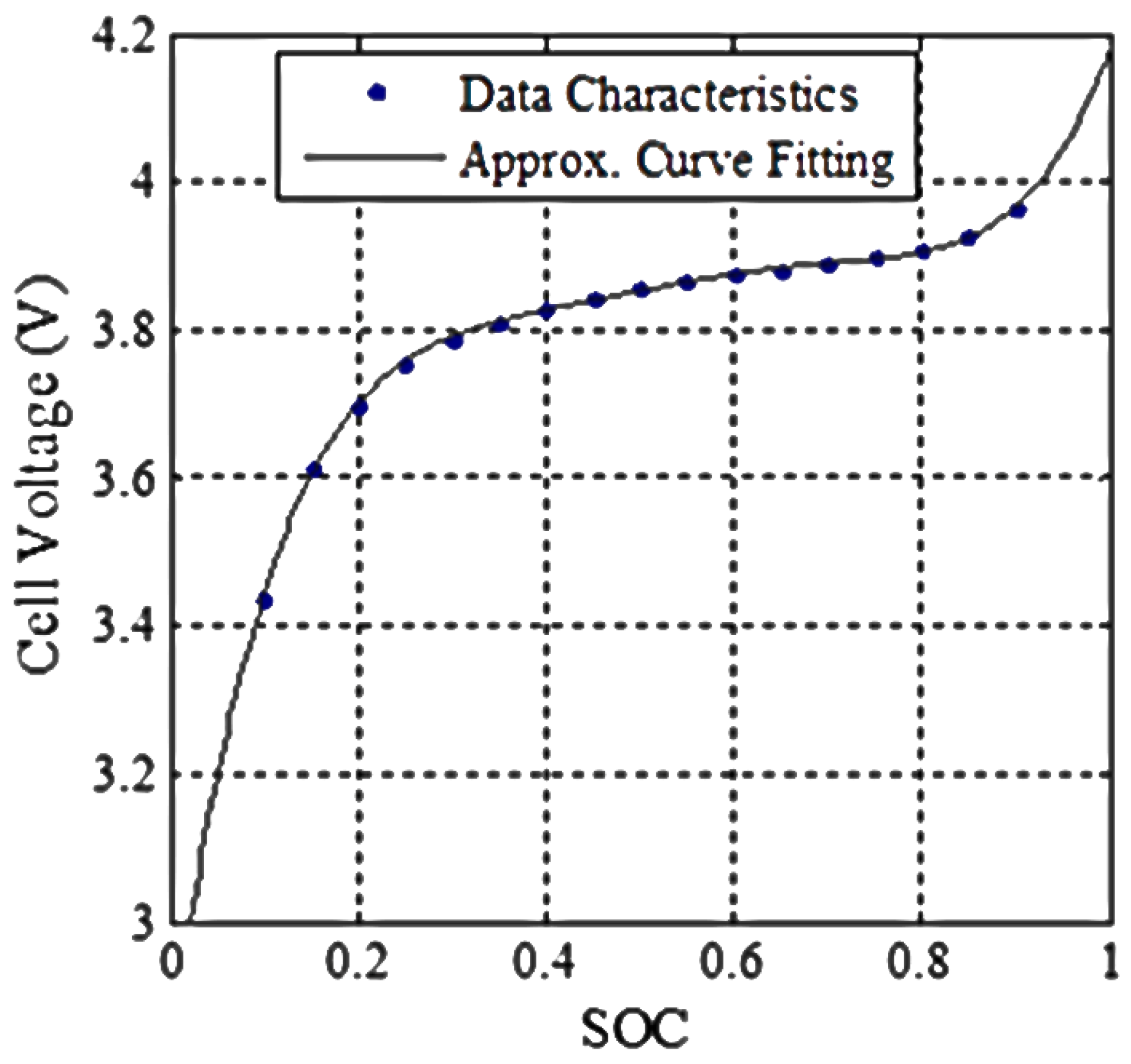
3.1. Modeling of EV Lithium-Ion Battery

The essential task to develop a model of charge equalization controllers is to model the EV Li-ion battery in order to model the optimal power rating, implement the equalization operation, and enhance the performance of equalization. A Li-ion battery of nominal 15.5 Ah and 3.7 V is chosen in EV applications because of its high output rating [6,7,8,12]. The generic model is applied for the Li-ion battery because this model is flexible to configuration at any values for Li-ion, lead-acid, Ni-Cd, and Ni-MH batteries [28]. The generic model is similar to the Shepherd model, except it is free of algebraic loop problems. This model is applicable for both charging Equation (1) and discharging Equation (2) batteries to implement the equalization operation and to enhance its performance. The battery model is considered to be operated at normal operating temperature that required by the EV system although the lithium-ion battery has the negative temperature effect on the internal resistance. When battery is fully charged the voltage increases rapidly. That refers to the polarization resistance in battery model as it increases abruptly until the battery is fully charged due to end-of-charge characteristics of the lithium-ion battery. The battery model uses the SOC as state variable to obtain the accurate manufacturing characteristics. The internal impedance might be determined from the second pulse transient voltage response during the rest period and related with the SOC using empirical equation by polynomial curve fitting approximation [29].
Charging model of Li-ion battery:
V c h = E 0 K Q Q + 0.1 Q i * K Q Q Q Q + A e B Q R i
Discharging model of Li-ion battery:
V d i s c h = E 0 K Q Q Q i * K Q Q Q Q + A e B Q R i
where Vch is the battery voltage at charge, Vdisch is the battery voltage at discharge, E0 is the constant voltage (V), R is the internal resistance (Ω), K is the polarization constant (Ah−1) or polarization resistance (Ω), i is the battery current (A), Q′ is the extracted capacity (Ah), that is, 0 t i ( t ) d t , Q is the maximum battery capacity (Ah), A is the exponential voltage (V), B is the exponential capacity (Ah−1), and i* is the low frequency current (A).
The voltage profiles of the Li-ion battery model at different charge and discharge rates are shown in Figure 2a,b, respectively. These profiles are measured with a current pulse of 1 C, C/2, and C/3 charge and discharge rates for 300 s at 300 s intervals. The waveforms in Figure 2a,b show the uniform characteristics in all charge and discharge profiles.
The open circuit voltage (OCV) is counted using the nonlinear equation on the basis of the actual SOC of the battery as Equations (1) and (2). The model evaluation of the Li-ion battery in terms of the OCV vs. SOC relationship representing the data characteristics is shown in Figure 3 [12,23]. The OCV curve is obtained at SOC variations with the consideration of constant internal resistance and temperature with nonlinear model equation and actual battery charge. The relationship model of the Li-ion battery is applied to model the optimal power rating and to fix the equalization conditions on the basis of the cell voltage and SOC difference. Equation (3) presents the approximate relationship between the OCV (VOC) and SOC of the Li-ion battery found by curve fitting the experimental values with a norm of residuals of 0.016062 from the Figure 3. The SOC–OCV relationship is used to estimate SOC of the Li-ion battery [7,9,28,29,30,31,32,33,34,35,36,37,38,39,40] for implementing the equalization control algorithm of the equalization controller model. During the process of charge equalization the controller records the terminal voltage value of each cell and converts to SOC value of the respective cell by using the relationship Equation (3), considering negligible temperature effect on the internal resistance of battery model. The controller detects the unprotected, overcharged, or overdischarged cell based on the SOC difference value between the average SOC and the SOC value of the specific detect cell:
V O C = 21.049 × S O C 5 57.837 × S O C 4 + 62.228 × S O C 3 32.997 × S O C 2 + 8.9149 × S O C + 2.824

3.2. Modeling of Optimal Power Rating

The equalization controller model is applicable for n battery cells of a pack connected in series. As discussed in the preceding section, the fifth cell is considered as overdischarged. Thus, the battery cell needs to be charged. With this assumption, the optimal power rating could be obtained by satisfying Equations (4) and (5). Equation (4) means that the amount of charge Q5 stored in Cell-5 over the equalization period Teq must be equal to the mean charge transferred from all other cells at the same duration. Equation (5) means that the average output power Pout_average that is extracted from the cells excluding the overdischarged cell is the same as the converter efficiency η times the average input power Pin_average that is transferred in the overdischarged cell:
Q 5 ( T e q ) = 1 n 1 ( i = 1 4 Q i ( T e q ) +   k = 6 n Q i ( T e q )   )
P o u t _ a v e r a g e = η × P i n _ a v e r a g e
The amount of charge in Cell-5 Q5(t) at time t, the average output power Pout_average, and the average input power Pin_average of the equalization controller are presented in Equations (6)–(8), respectively, in terms of the equalization current Ieq, the equalizer input current Iin, the equalizer output current Iout, and the capacitance C of the 15.5 Ah Li-ion battery:
Q 5 ( t ) = Q 5 ( 0 ) +   Q 5 ( T e q ) =   Q 5 ( 0 ) +   I e q T e q =   Q 5 ( 0 ) +   ( I o u t I i n ) T e q
P o u t a v e r a g e = 1 T e q 0 T e q P o u t ( t ) d t = 1 T e q 0 T e q V 5 ( t ) I o u t d t = 1 T e q C 0 T e q Q 5 ( t ) I o u t d t      = 1 T e q C 0 T e q ( Q 5 ( 0 ) + ( I o u t I i n ) t ) I o u t d t      = ( V 5 ( 0 ) + 1 2 C ( I o u t I i n ) T e q ) I o u t
P i n a v e r a g e = 1 T e q 0 T e q P i n ( t ) d t = 1 T e q 0 T e q ( V 5 ( t ) + i = 1 4 V i ( t ) + i = 6 n V i ( t ) ) I i n d t      = 1 T e q C 0 T e q ( Q 5 ( t ) + i = 1 4 Q i ( t ) + i = 6 n Q i ( t ) ) I i n d t      = ( i = 1 n V i ( 0 ) + 1 2 C ( I o u t n I i n ) T e q ) I i n
The relationships between the equalization period Teq and the equalization current Ieq as well as between the equalization period Teq and the equalizer input current Iin are determined using Equations (9) and (10), respectively, by solving Equations (4) and (5) with the values from Equations (6)–(8):
T e q = C I e q ( ( 1 n 1 ( i = 1 4 V i ( 0 ) + i = 6 n V i ( 0 ) ) V 5 ( 0 ) ) ( 1 n i = 1 n V i ( 0 ) + ( 1 n i = 1 n V i ( 0 ) ) 2 1 η n ( ( 1 n 1 ( i = 1 4 V i ( 0 ) + i = 6 n V i ( 0 ) ) ) 2 ( V 5 ( 0 ) ) 2 ) ) )
T e q = C I i n ( 1 n i = 1 n V i ( 0 ) + ( 1 n i = 1 n V i ( 0 ) ) 2 1 η n ( ( 1 n 1 ( i = 1 4 V i ( 0 ) + i = 6 n V i ( 0 ) ) ) 2 ( V 5 ( 0 ) ) 2 ) )
These two relationships are utilized to estimate the equalization time by fixing the equalization current so that the equalization converter produces minimal stress to the switches and rectifier diodes and the charge equalization controller model performs in accord with the design considerations. To simplify the modeling of the charge equalization controller for a large number of series-connected battery cells in a pack, the equalization current Ieq could be obtained using Equation (11), which is approximately equal to the equalizer output current Iout and the equalization period Teq with respect to the SOC in Equation (12):
I e q =   I o u t I i n = I o u t ( 1   I i n I o u t )   I o u t ( 1   V 5 η i = 1 n V i )     I o u t
T e q =   Q 5 ( T e q ) I e q = Q T o t a l I e q S O C 5 ( T e q )     Q T o t a l I o u t S O C 5 ( T e q )
where QTotal is the total capacity of a single battery cell and SOC (Teq) is the SOC difference level within Teq noted by ∆SOC.

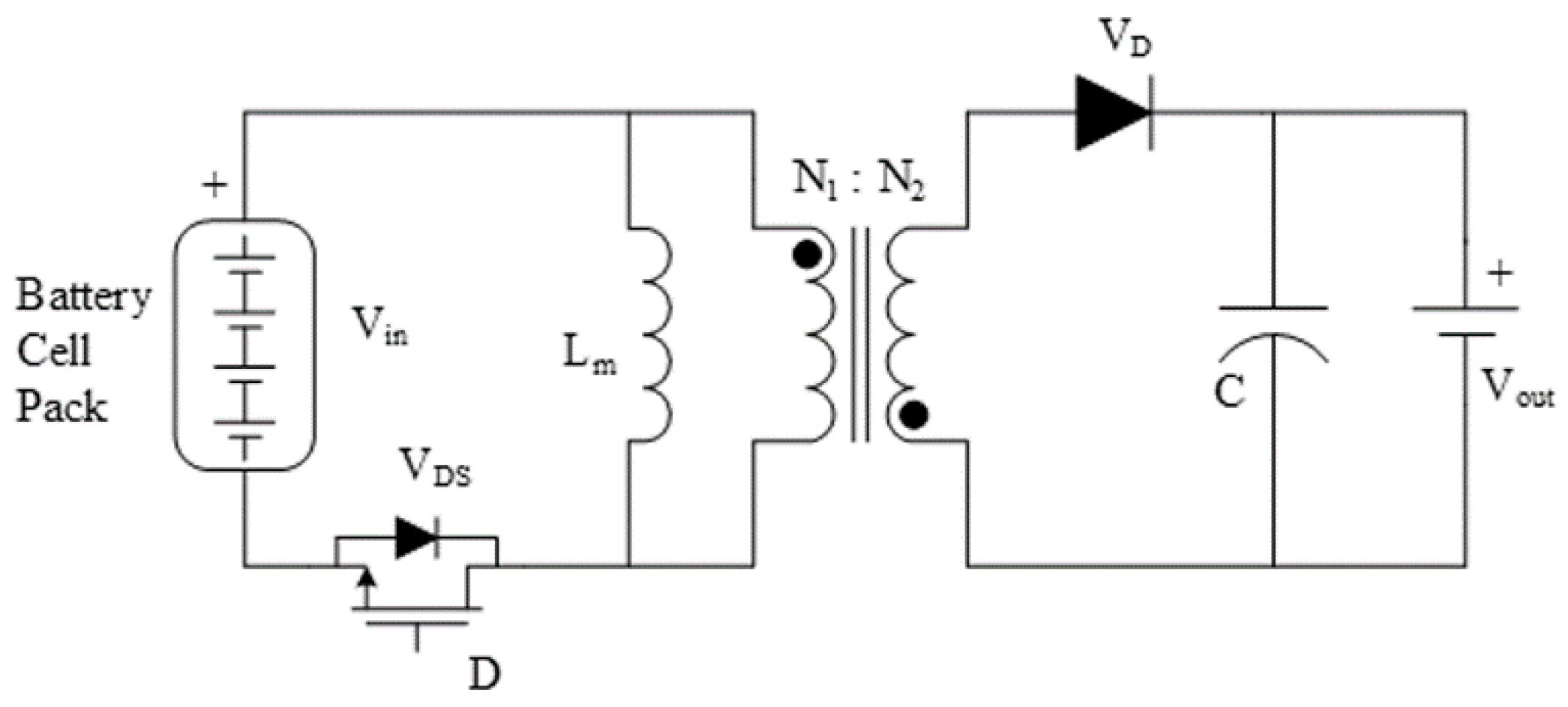
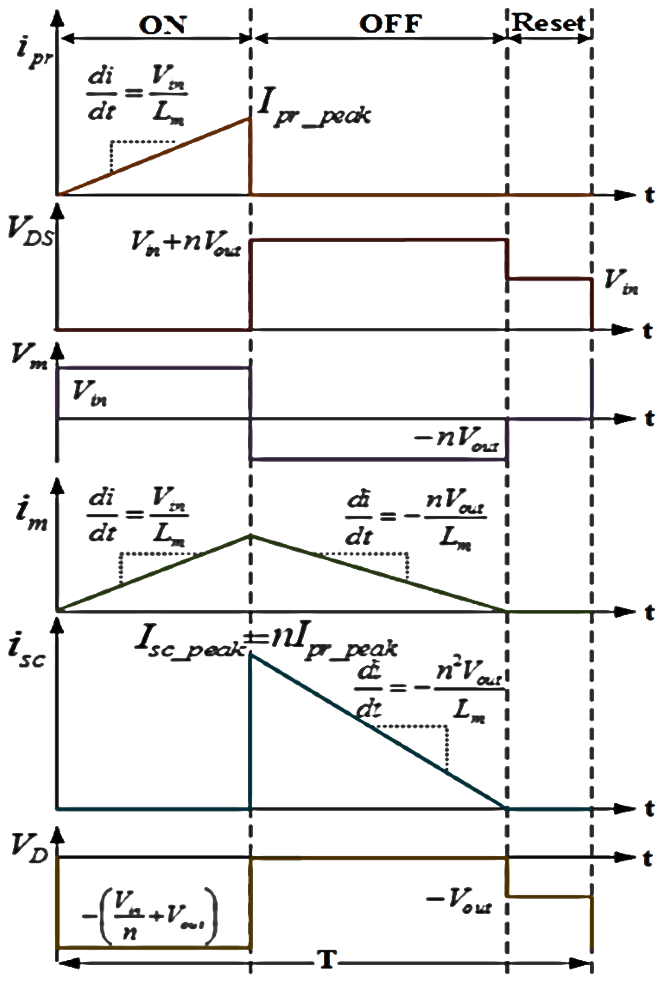
3.3. Modeling of Bidirectional Flyback DC–DC Power Converter

The charge equalization controller needs the consistent design of the power converter. Meanwhile, it primarily deals with the transfer of equalization current to equalize the imbalanced battery cell. A flyback DC–DC power converter is utilized in this proposed system, as shown in Figure 4, which transfers power by storing power in the electromagnetic field of a transformer magnetizing coil in the primary circuit during the duty ON stage of the switch (0 < t ≤ DT); then, the stored power is delivered to the secondary circuit during the duty OFF stage of the switch (DT < t ≤ T). The operation of the flyback DC–DC converter is considered with discrete current mode so that it can perform reliably without the reverse recovery blocking problem in the rectifier diode [20,41,42].
The modeling of the flyback DC–DC power converter is designed to configure its electrical components with the best parameter values which has the low and tolerable voltage and current stresses on the power metal-oxide-semiconductor field-effect transistor (MOSFET) switch and rectifier diode and with the desired power, voltage, and current levels. For this, the converter components need to be selected with the maximum stress value so that the switch can operate safely without any peak voltage and current effect [43,44,45]. The maximum duty of switching PWM signal Dmax for the flyback DC–DC converter is considered to operate the switch in the safe region of voltage stress calculated using Equation (13) [46]:
D m a x = V d s _ n o m V i n _ m i n V d s _ m i n +   V d s _ n o m V i n _ m a x
where Vin_min is the minimum voltage for the battery cell pack, Vin_max is the maximum voltage for the battery pack, Vds_min is the minimum voltage stress of the switch, and Vds_nom is the nominal voltage stress of the switch (≥30% margin of maximum drain–source voltage).
The mutual inductance of transformer Lm can be counted using Equation (14) [41]:
L m = ( η V i n _ m i n D m a x ) 2 2 P i n f
where Pin is the input power and f is the switching frequency.
The turns ratio of transformer n and the filter capacitor C of the DC–DC converter can be calculated using Equations (15) and (16), respectively [41]:
n =   N 1 N 2   = η V i n _ m i n D m a x ( V 0   V f )   ( 1 D m a x )
C =   η P i n D m a x ( V 0   V f ) 2   f
where N1 is the number of primary turns, N2 is the number of secondary turns, V0 is the output voltage, Vf is the forward voltage of the rectifier diode, and η is the converter efficiency, which is considered to regulate the required converter output power by setting the mutual inductance of the flyback transformer, transformation ratio, voltage transmission factor, and filter capacitor of the power converter.
The maximum voltage stresses on the MOSFET switch and diode of the flyback DC–DC converter are given in Equations (17) and (18) [41]:
V S _ D S _ m a x =   V i n _ m a x + n V o u t
V S _ D _ m a x =   V i n _ m a x n + V o u t
where VS_DS_max is the maximum voltage stress on the MOSFET switch, Vin_max is the maximum input in the primary side, Vout is the output voltage, and VS_D_max is the maximum voltage stress on the diode.
The total power loss of the converter is calculated using Equation (19) [41]:
P C L _ T o t a l =   P L _ D S + P L _ S W +   P L _ P r i   + P L _ S e c   + P L _ D   + P L _ L m
where PCL_Total is the total converter power loss, PL_DS is the MOSFET conduction loss, PL_SW is the switching loss, PL_Pri is the primary winding loss, PL_Sec is the secondary winding loss, PL_D is the diode conduction loss, and PL_Lm is the mutual inductor resistance loss.
The working efficiency of the converter is calculated using Equation (20):
η =   P o u t P i n =   P i n   P C L _ T o t a l P i n
The efficiency of the power converter is initially considered as 85% to obtain the converter parameters so that the total converter power loss could be calculated to find the actual converter efficiency.

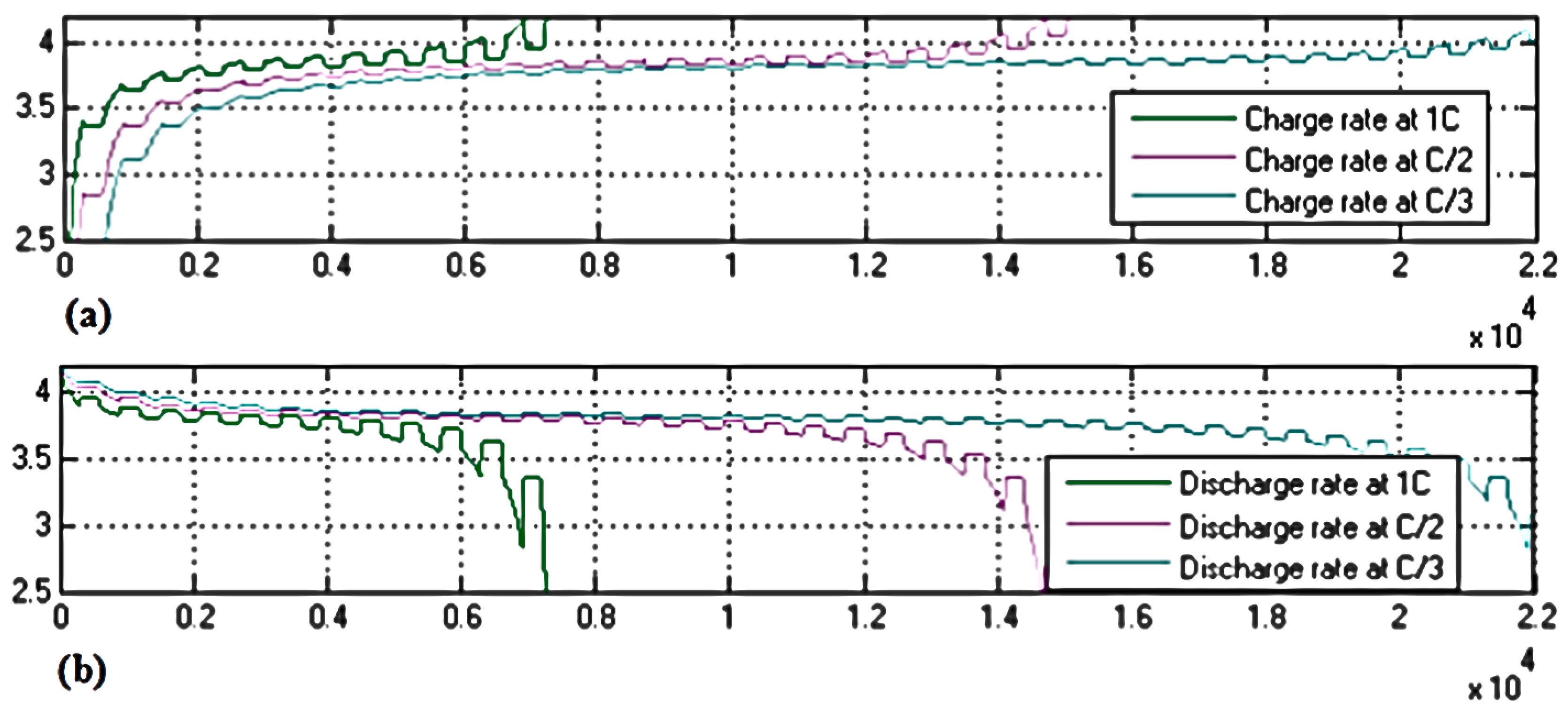
3.4. Modeling of Charging and Discharging of Li-Ion Battery

The charging and discharging of Li-ion batteries are important issues in modeling the charge equalization controller to sustain the apt characteristics of the battery. The methods introduced for the charging and discharging of Li-ion batteries are constant current–constant voltage (CC–CV) control [42,46] and discontinuous current mode (DCM) control [41], respectively. These control processes are established for Li-ion batteries with flyback DC–DC converters [41,42].

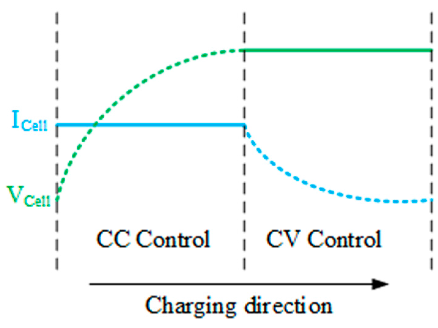
3.4.1. Constant Current–Constant Voltage Control for Charging

The CC–CV control for Li-ion battery charging is presented in Figure 5. At the beginning of charging, the battery is precharged by the trickle current charge method until the battery voltage exceeds the threshold level because the impedance of the battery with respect to SOC and temperature is affected [26]. Then, the cell is charged as the cell voltage increases exponentially with constant current by duty adjustment as long as the voltage value reaches the operating mean level. Sequentially, the charging continues with a constant voltage by PI control until the current reaches approximately 0.1 C [26,42].

3.4.2. Discontinuous Current Mode Control for Discharging

The DCM control is the basic flyback DC–DC converter operation that operates at three states, namely, ON, OFF, and Reset, in a single switching period Figure 6 [41]. At the ON state of the switch, the primary transformer current and magnetizing inductor current grow with a slope defined by Equation (21), and the magnetizing inductor voltage is the same as the input voltage. The current of the secondary side of the transformer is zero, and the voltage across the diode is defined by Equation (18) [26,41].
d i d t =   V i n L m
At the OFF state of the switch, the flyback converter transfers the energy to the secondary side for charging the battery as the diode conducts. The secondary current Isc_peak shifts to a level n times that of the primary peak current Ipr_peak and then decreases with a slope mentioned in Equation (22). The magnetizing inductor current falls with the slope defined by Equation (23) as the voltage of the magnetizing inductor drops to the output voltage Vout multiplied by turns ratio n. As the primary current is zero, the switch voltage stresses are high as presented in Equation (17) [26,41].
d i d t =   n 2 V o u t L m
d i d t =   n V o u t L m
At the Reset state, the switch and the diode become unconducted and the magnetizing inductor neither stores nor releases energy. The voltage values across the switch and the diode are as the same as their side values [26,41].

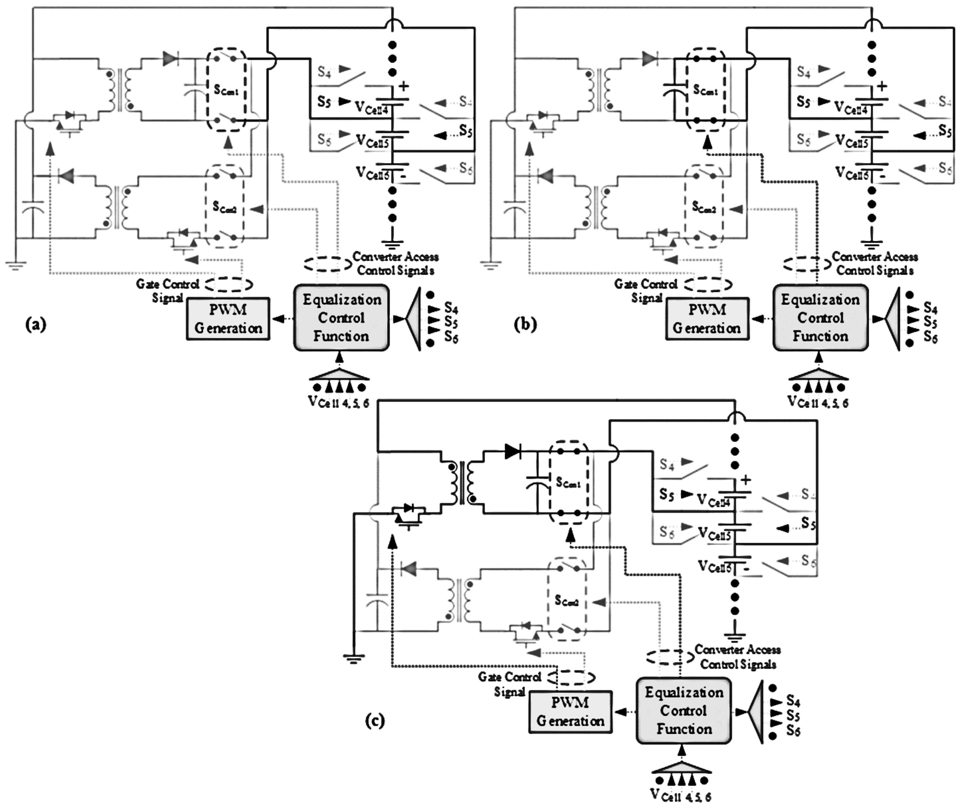
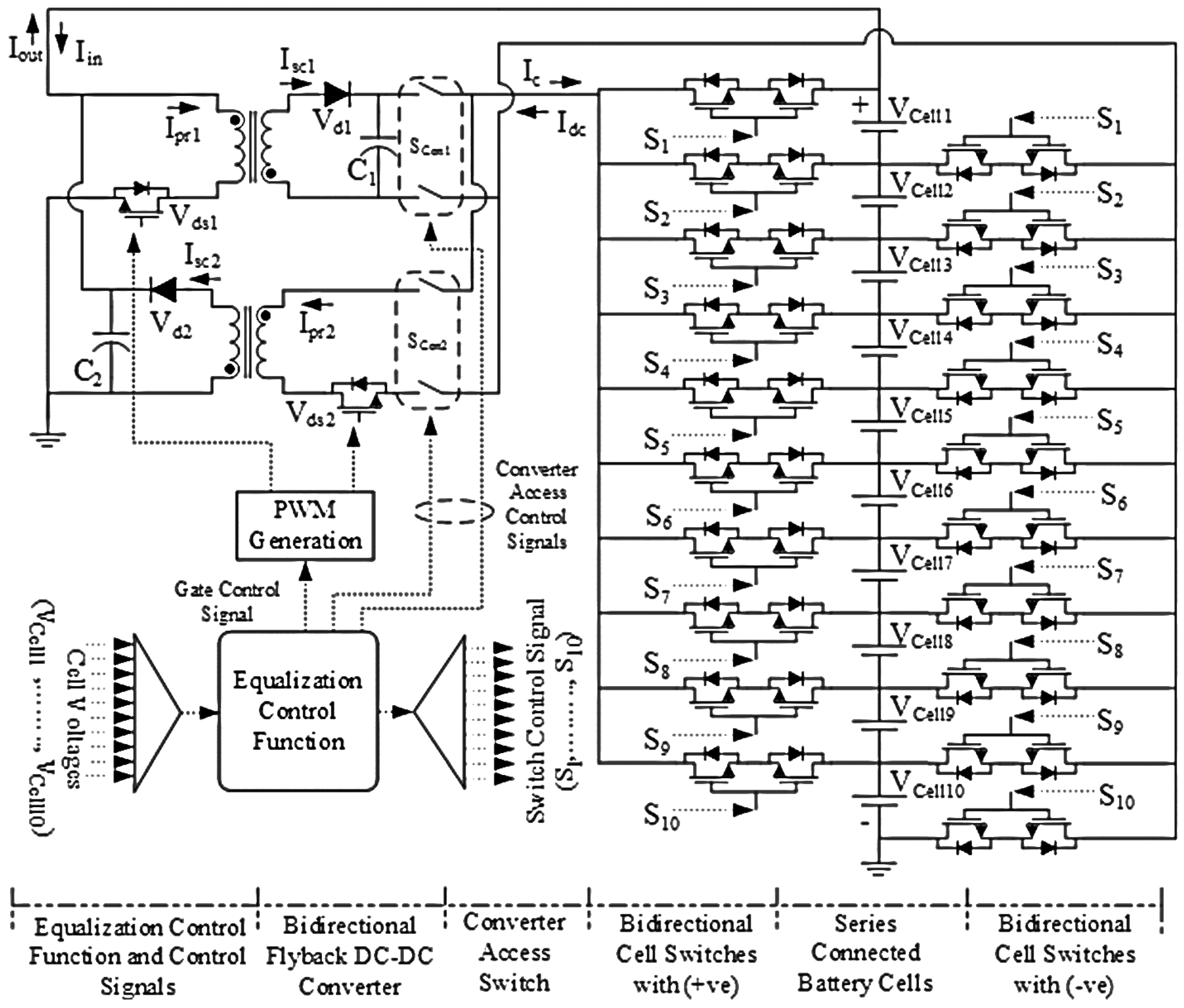
3.5. Modeling of Charge Equalization Controller Circuit

The overview of the charge equalization controller circuit, as shown in Figure 1, is elaborated in Section 2. The controller circuit is modeled through simulation to test and analyze the result of equalization with a set of 10 series-connected Li-ion battery cells. The models of the battery cells are configured with nominal 15.5 Ah and 3.7 V as described in Section 3. To model the small-scale equalization controller, the flyback DC–DC power converter is designed with the values of converter parameters using Equations (13)–(18). To execute the bidirectional operation of the converter and the controller, two flyback DC–DC power converters are utilized as the forward flyback DC–DC converter for charging overdischarged cells and as the reverse flyback DC–DC converter for discharging overcharged cells. The converter model parameters are presented in Table 1, considering a converter input power of 10 W and a switching frequency of 100 kHz.
The bidirectional cell switches of the MOSFET switch and the converter access switches of relay are used to construct the electric pathway between the converter and the battery cells. The control function is embedded with the algorithm to detect the unprotected and unequalized cell with the conditions of overcharge, overdischarge, and minimum ∆SOC, and to activate all the consecutive processes. The control processes are executed by the controller such that the equalization is performed accordingly by transferring the equalization current from a cell pack to an overdischarged cell or vice versa. The equalization in the proposed charge equalization controller is maintained by distributing the energy from the battery cells among the cells or cell on the basis of the charge or discharge operation without an extra power source or sink, respectively.

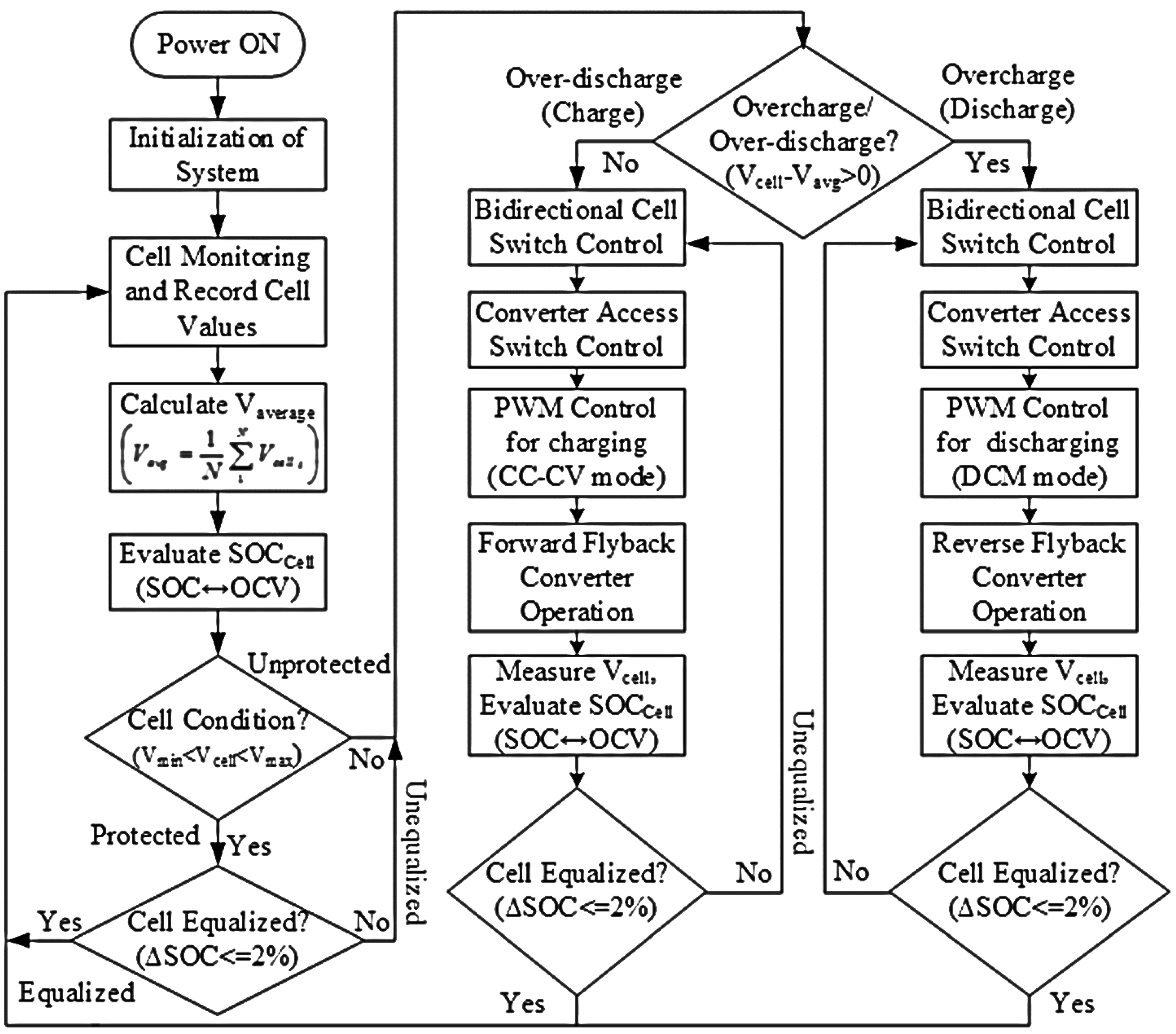
4. Charge Equalization Controller Algorithm

The charge equalization controller is operated to equalize the series-connected battery cells by exchanging energy through the equalization current from an unequalized cell to a cell pack or vice versa employing the equalization controller algorithm as shown in Figure 7. The equalization of series-connected battery cells is a continuous process. After the initialization of the system, the equalization control function acts for cell monitoring to record the cell voltage levels and determine whether the cell conditions are operating within the normal range (i.e., 3.72–3.88 V). The control function calculates the average of cell voltages and tests the charge level of battery cells with the maximum difference of the state of charge (∆SOC) among all of the cells in terms of the OCV vs. SOC relationship. If a cell is detected as unprotected (i.e., it is out of the normal operating range) or unequalized (i.e., it has more or less 2% ∆SOC than the average value), the equalization control function activates the bidirectional cell switch, turns ON the converter access switch depending on whether the detected cell is overcharged or overdischarged, and finally starts the flyback DC–DC converter operation with PWM signals to the MOSFET switch to allow the steady equalization current to flow until the cell becomes equalized. The bidirectional flyback DC–DC converter is composed of two unidirectional flyback DC–DC converters, namely, forward and reverse flyback converters, for charging and discharging battery cells, respectively.
The charge equalization controller follows the control algorithm as stated in Figure 7 and executes the operation flow route. The control function communicates all the bidirectional cell switches, converter access switches, and converter MOSFET gates to stimulate the whole controller for the equalization process as the switches, diodes, and converters act as ideal. For clear elaboration of the equalization controller circuit model, the operation processes are illustrated in three steps by considering the battery Cell-5 as an overdischarged cell from the series-connected cell pack:
Step 1. When the equalization controller identifies Cell-5 as overdischarged, it sends “1” logic to bidirectional cell switch, (S5) corresponding to Cell-5, and “0” logic to that associated with all other cells. A pathway of the current flow for Cell-5 is shown in Figure 8a.
Step 2. As shown in Figure 8b, the equalization control function sends the converter access switch signal to the converter access switch to build an electric path for the access of the forward flyback converter because the detected cell is overdischarged.
Step 3. In this step, the converter MOSFET gate is fired with PWM signals to activate the operation of the forward flyback converter by sending gate control signals. Finally, an equalization current path is generated through the converter to transfer the required energy to the detected Cell-5 from the cell pack as depicted in Figure 8c. Hence, the equalization is performed along with the consequences of the three steps by means of the equalization control algorithm.
The charge equalization controller algorithm allows the transfer of excessive energy from an overcharged cell to a cell pack or the transfer of required energy from a cell pack to an overdischarged cell through the converter. The proposed algorithm operates the equalization controller for overcharged and undercharged cells based on the maximum ∆SOC (i.e., difference of the state of charge between the detected cell and the average level) of the cell. If the undercharged cell has a position with more ∆SOC than the overcharged cell or vice versa or other cell, the algorithm executes the controller for equalization of that cell first and then repeats again and again until all cells are equalized within the expected equalization range. This controller algorithm has the flexibility to monitor and equalize both series and parallel cells by using a parallel cell selection switch to the converter. The algorithm functions as it is to operate the equalization controller. Thus, the equalization controller may protect the battery cells from damage and life reduction, as well as enhance the overall performance of the energy storage system toward an efficient EV drive and sustainable renewable energy applications.

5. Results and Discussion

The proposed charge equalization controller model is implemented with a controller circuit model of 10 series-connected Li-ion battery cells to test and analyze the performance of the model. The model circuit of this charge equalization controller is shown in Figure 1, and the operation of the circuit is described in Section 2 and Section 4. The charge controller model, which is an aggregate of individual models an Li-ion battery, power rating, and power converter, is particularized in the preceding section. To find the equalization results, all parts are combined, and each parameter value is configured accordingly. The setup of the charge equalization controller model is arranged with all measurement and display tools to obtain and view the outputs of the equalization controller.

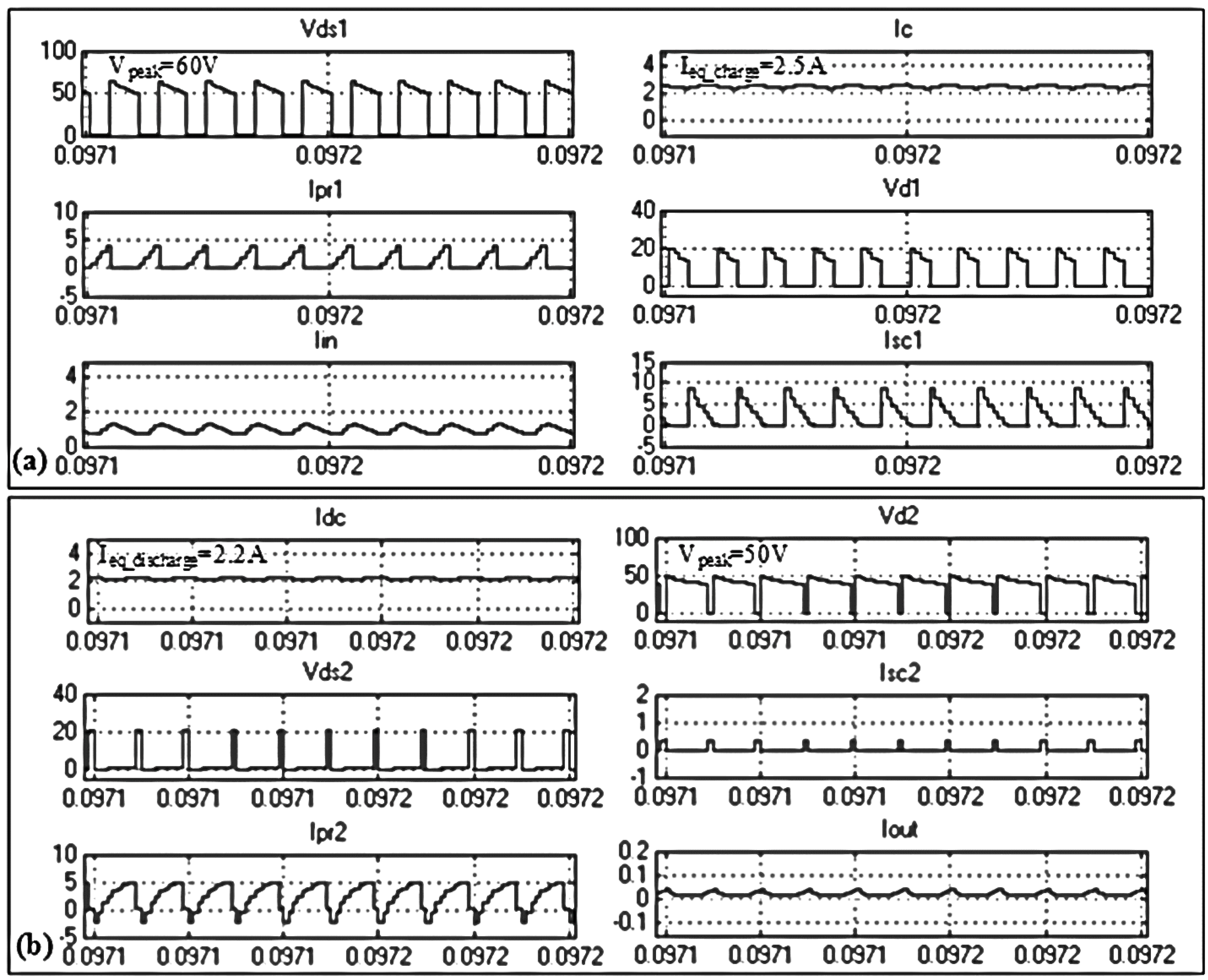
5.1. Bidirectional Flyback DC–DC Converter Output

The equalization controller customs with the bidirectional flyback DC–DC power converter to transfer the power from an overcharged cell to a cell pack or from a cell pack to an overdischarged cell for equalization. To execute the equalization for both charging and discharging battery cells, the bidirectional flyback converter operates as the forward flyback converter for charging overdischarged cells and as the reverse flyback converter for discharging overcharged cells. For cell charging, the forward flyback converter is inputted with a total cell pack voltage of 38.3 V of 10 series-connected cells. The output waveforms of the forward flyback DC–DC converter are shown in Figure 9a. The input of the reverse flyback converter is the overcharge cell voltage of more than 3.85 V based on the ∆SOC (minimum 10%) while discharging the cells, and the excessive charge is distributed to all battery cells. Figure 9b depicts the output of the reverse flyback DC–DC converter.
As shown in Figure 9, the voltage stresses on the MOSFET switch of the forward converter and on the diode of the reverse converter are 60 and 50 V, respectively, which are in the safe range. The equalization current is maintained at 2.5 A at charge and 2.2 A at discharge. The total power loss and overall efficiency of the converter are obtained using Equations (19) and (20), respectively. The proposed charge equalization controller operates at 91% efficiency.

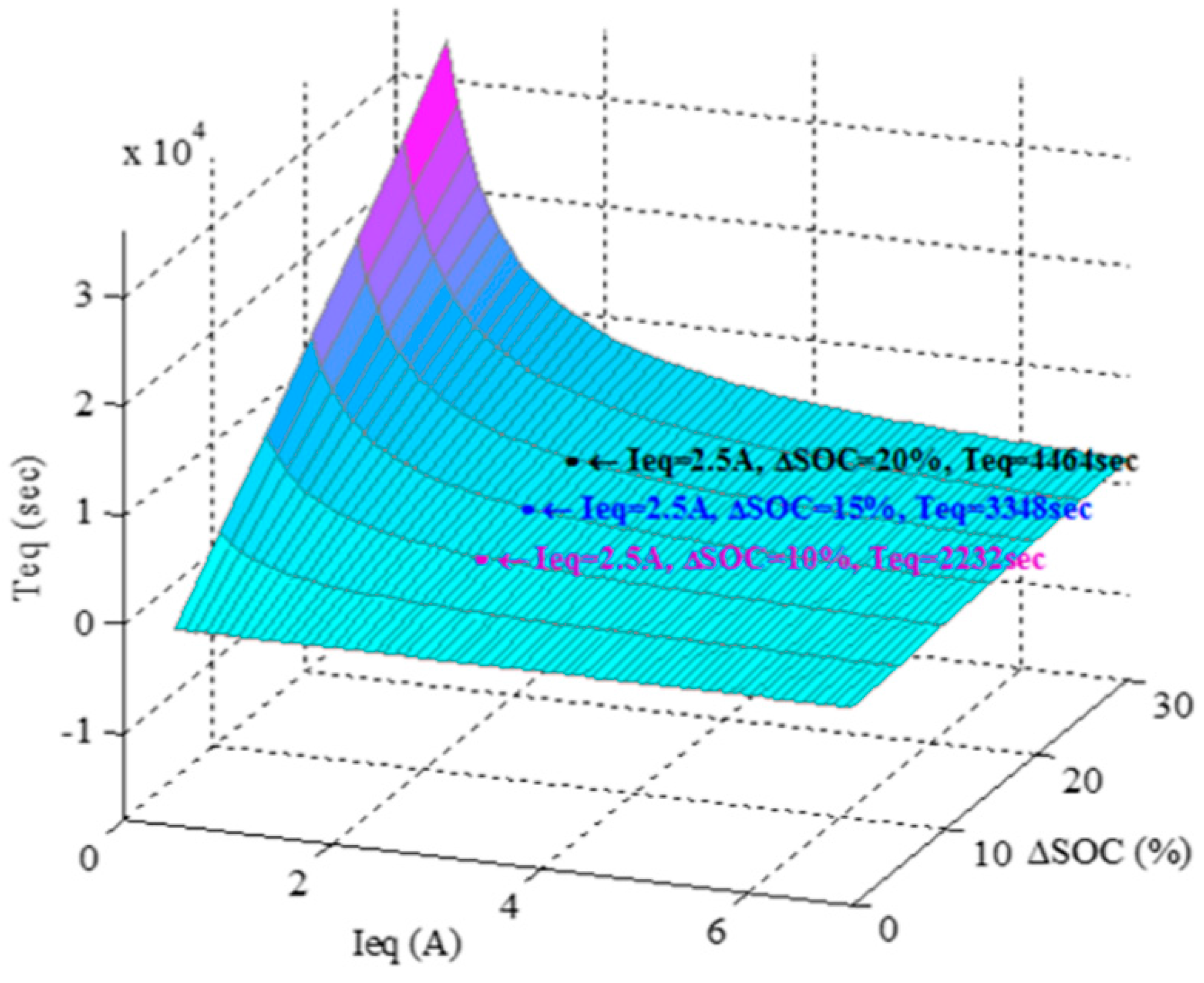
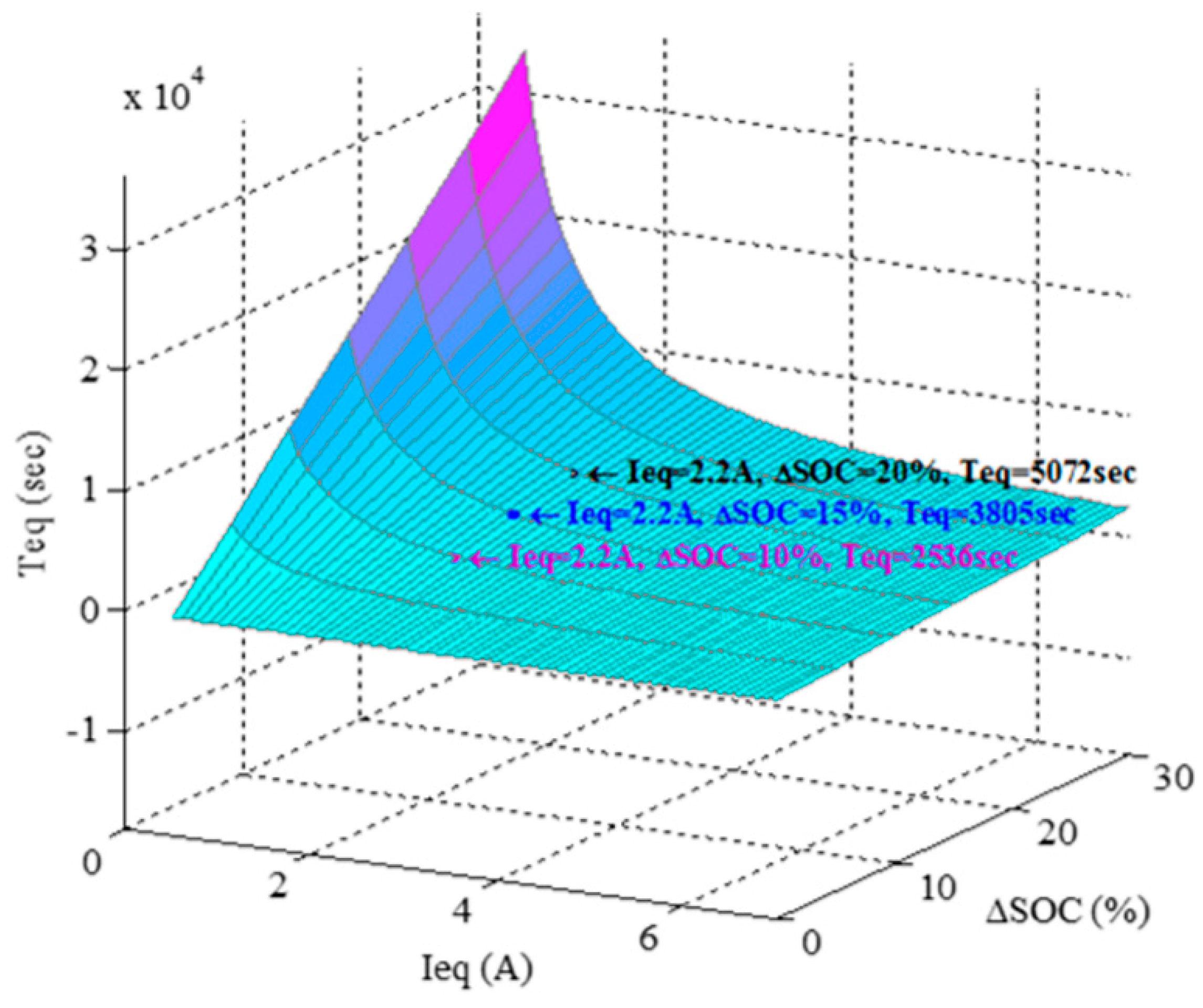
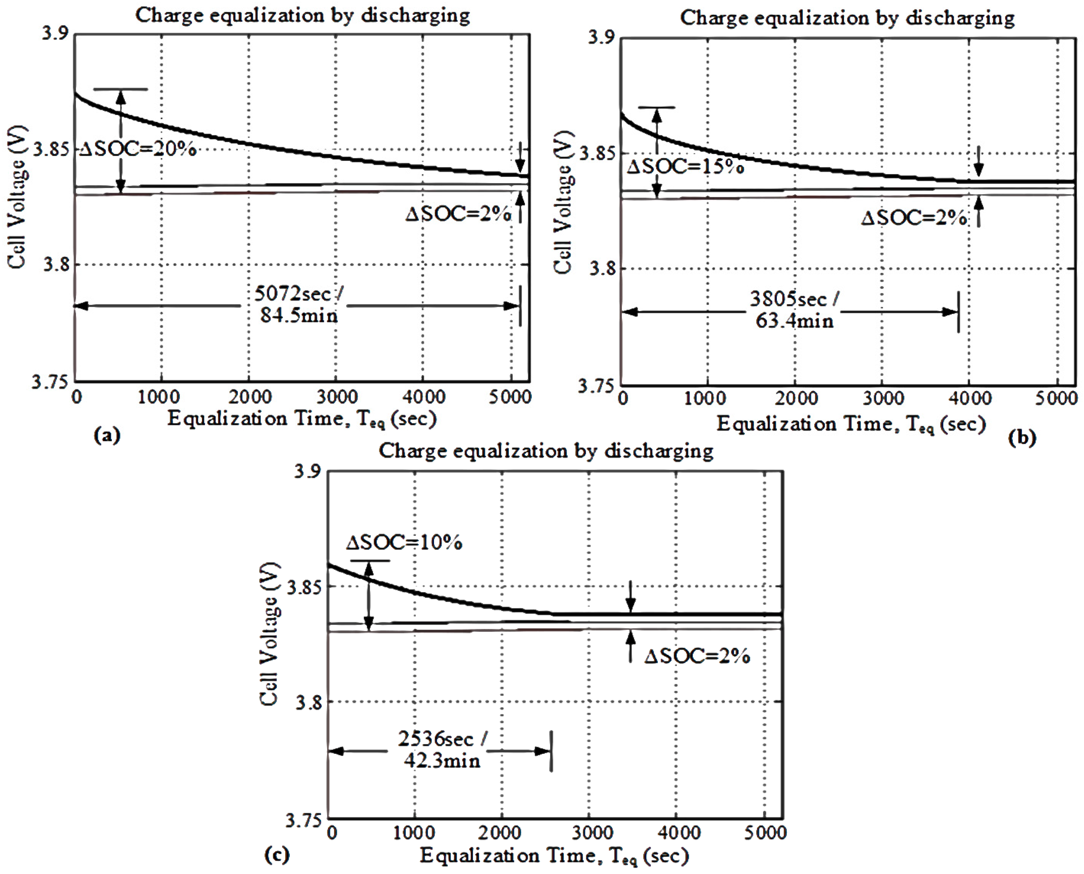
5.2. Equalization Output

The charge equalization controller model performs for the equalization of 10 series-connected Li-ion battery cells by using the proposed equalization control algorithm. The equalization starts whenever a cell is detected as overcharged or overdischarged on the basis of the normal operating voltage range between 3.72 and 3.88 V, which corresponds to a minimum ∆SOC of 10% for equalization testing. As shown in Figure 10, the operation of the equalization controller is executed by activating the bidirectional cell switch, converter switch, PWM generation, and forward flyback DC–DC converter for the detected battery cell to be charged upholding the requirement of the charge equalization control surface model. The equalization output for an overdischarged cell with different ∆SOCs and an equalization current of 2.5 A is presented in Figure 11a–c. The equalization process continues until ∆SOC reaches a minimum of 2%. In Figure 11a, the cell with 20% ∆SOC reaches the equalization level in 74.4 min, whereas the cells with 15% ∆SOC in Figure 11b and 10% ∆SOC in Figure 11c are equalized in 55.8 and 37.2 min, respectively.
As shown in Figure 12, the process of the equalization controller is accomplished by activating the bidirectional cell switch, the converter switch, PWM generation, and the reverse flyback DC–DC converter to discharge the detected battery cell and maintain the condition of the charge equalization control surface model. The equalization output is displayed in Figure 13a–c for an overcharge cell with different ∆SOCs and an equalization current of 2.2 A. The equalization process is continued until the ∆SOC reaches a minimum of 2%. In Figure 13a, the cell with 20% ∆SOC reaches the equalization level in 84.5 min, whereas the cells with 15% ∆SOC in Figure 13b and 10% ∆SOC in Figure 13c are equalized in 63.4 and 42.3 min, respectively. The equalization performances demonstrated for both overdischarged and overcharged cells are proven ideal and timely on the basis of the model values of the charge equalization surface that validates the operation of the proposed charge equalization controller algorithm for series connected lithium-ion battery storage systems.

5.3. Performance Comparison of the Proposed Charge Equalization Controller Model

The performance comparison of the proposed charge equalization controller model with the present passive and active equalization controllers is presented in Table 2 [9,10,11,12,13,14,15,16,17,18,19,20,21,22]. The comparison is based on equalization type, equalization speed, execution, control difficulty, and stress. The comparison study also includes the overall efficiency, power loss, size and cost of model design, and required MOSFET switches. Moreover, the evaluation covers the merits and demerits of the charge equalization controller models. The resistor current shunt equalization controller is simple in design and control, and cost effective. Nonetheless, its equalization time and efficiency are poor; it needs thermal management because of high power loss due to heat [12,13,14,15]. Conversely, the switched capacitor-based charge equalization controller is simple in implementation and cheap. Nevertheless, its equalization time and efficiency are satisfactory [16,17]. The multi-winding transformer charge equalization controller is good in equalization speed, however, it suffers from high voltage and current stresses, magnetizing losses, an expensive and bulky design, and complex control [18,19]. The flyback converter and resonance converter-based charge equalization controllers are good in equalization and efficiency, but their execution is complex and expensive [10,11,12,13,14,15,16,17,18,19,20,21,22]. Meanwhile, the buck–boost converter charge equalization controller features excellent equalization speed and efficiency, but its design is complex, costly, and requires intelligent control [23,24,25]. The proposed charge equalization controller has excellent equalization speed and less execution trouble. It has comparatively low cost, negligible power loss, and good efficiency. The proposed model is a bidirectional and active equalization controller for both charging and discharging battery cells and can be implemented in modularized design for high power and voltage applications especially in EVs, although it needs closed loop intelligent control.

6. Conclusions

A charge equalization control model for monitoring and equalizing Li-ion battery cells is presented with comprehensive model design and implementation. The model is executed for cell monitoring, cell protection, and charge equalization of 10 series-connected Li-ion battery cells. This paper presents a system overview of the CEC model of Li-ion battery cells and the operating principle with the proposed algorithm, including the modeling of the Li-ion battery, optimal power rating, flyback DC–DC converter, and equalization circuit. The results of the CEC include the outputs of forward and reverse flyback DC–DC converters and the equalization outputs for both charging and discharging Li-ion battery cells. The converter outputs are found in the range of standard equalization current and tolerable stress. The equalization outputs originate at perfect timing as compared with the charge equalization control surface model at ∆SOC values of 20%, 15%, and 10% during the charge and discharge modes of battery cells. The overall outputs reveal that the charge equalization control process with the proposed model is easy to execute, excellent in equalization speed, and efficient with low power loss and stress. The equalization performance demonstrates an accurate balance to maintain the charge levels of battery cells at a minimum of 2% ∆SOC within the operating voltage range. From the comparison validation, it could be stated that this CEC model might be applied as compatible for the monitoring and equalization of series-connected cells for different battery-based energy storage systems. This developed CEC model could be designed for further development of Li-ion battery storage systems of high power and voltage in real time EV and sustainable energy applications.

Acknowledgments

This work was supported by the Universiti Tenaga Nasional Bold Multi-Track Incentive Grant RJO10289876 and the grant U-SN-CR-17-07 under Universiti Tenaga Nasional.

Author Contributions

M.A.H. and M.M.H. designed the study. M.M.H. and M.A.H. conducted experiments, analyzed and interpreted the data and wrote the manuscript. P.J.K., R.A.B. and A.M. are analyzed the collected data, edited the manuscript and M.A.H. is approved the manuscript for submission. All authors reviewed the manuscript.

Conflicts of Interest

The authors declare no conflict of interest.

References

  1. Hu, X.; Jiang, J.; Egardt, B.; Cao, D. Advanced Power-Source Integration in Hybrid Electric Vehicles: Multicriteria Optimization Approach. IEEE Trans. Ind. Electron. 2015, 62, 7847–7858. [Google Scholar] [CrossRef]
  2. Hannan, M.A.; Hoque, M.M.; Mohamed, A.; Ayob, A. Review of energy storage systems for electric vehicle applications: Issues and challenges. Renew. Sustain. Energy Rev. 2017, 69, 771–789. [Google Scholar] [CrossRef]
  3. Hu, X.; Murgovski, N.; Johannesson, L.M.; Egardt, B. Optimal Dimensioning and Power Management of a Fuel Cell/Battery Hybrid Bus via Convex Programming. IEEE/ASME Trans. Mechatron. 2015, 20, 457–468. [Google Scholar] [CrossRef]
  4. Hannan, M.A.; Hoque, M.H.; Peng, S.E.; Uddin, M.N. Lithium Ion Battery Charge Equalization Algorithm for Electrical Vehicle Applications. IEEE Trans. Ind. Appl. 2017, 53, 2541–2549. [Google Scholar] [CrossRef]
  5. Hoque, M.M.; Hannan, M.A.; Mohamed, A.; Ayob, A. Battery Charge Equalization Controller in Electric Vehicle Applications: A review. Renew. Sustain. Energy Rev. 2017, 75, 1363–1385. [Google Scholar] [CrossRef]
  6. Song, Z.; Hofmann, H.; Li, J.; Hou, J.; Han, X.; Ouyang, M. Energy Management Strategies Comparison for Electric Vehicles with Hybrid Energy Storage System. Appl. Energy. 2014, 134, 321–331. [Google Scholar] [CrossRef]
  7. Zou, Y.; Hu, X.; Ma, H.; Li, S.E. Combined State of Charge and State of Health Estimation over Lithium-Ion Battery Cell Cycle Lifespan for Electric Vehicles. J. Power Sources 2015, 273, 793–803. [Google Scholar] [CrossRef]
  8. Schuster, S.F.; Brand, M.J.; Berg, P.; Gleissenberger, M.; Jossen, A. Lithium-ion Cell-to-Cell Variation during Battery Electric Vehicle Operation. J. Power Sources 2015, 30, 242–251. [Google Scholar] [CrossRef]
  9. Hoque, M.M.; Hannan, M.A.; Mohamed, A. Optimal Algorithms for Charge Equalization Controller of Series Connected Lithium-Ion Battery Cells in Electric Vehicle Applications. IET Electr. Syst. Trans. 2017. [Google Scholar] [CrossRef]
  10. Hu, X.; Murgovski, N.; Johannesson, L.M.; Egardt, B. Comparison of Three Electrochemical Energy Buffers Applied to a Hybrid Bus Powertrain with Simultaneous Optimal Sizing and Energy Management. IEEE Trans. Intell. Transp. Syst. 2014, 15, 1193–1205. [Google Scholar] [CrossRef]
  11. Wang, Y.; Zhang, C.; Chen, Z. An Adaptive Remaining Energy Prediction Approach for Lithium-Ion Batteries in Electric Vehicles. J. Power Sources 2016, 305, 80–88. [Google Scholar] [CrossRef]
  12. Hoque, M.M.; Hannan, M.A.; Mohamed, A. Voltage Equalization Control Algorithm for Monitoring and Balancing of Series Connected Lithium-Ion Battery. J. Renew. Sustain. Energy 2016, 8, 1–15. [Google Scholar] [CrossRef]
  13. Javier, G.-L.; Enrique, R.-C.; Milanes-Montero, M.I.; Guerrero-Martinez, M.A. Battery Equalization Active Methods: Review Article. J. Power Sources 2014, 246, 934–949. [Google Scholar]
  14. Baronti, F.; Roncella, R.; Saletti, R. Performance Comparison of Active Balancing Techniques for Lithium-Ion Batteries. J. Power Sources 2014, 267, 603–609. [Google Scholar] [CrossRef]
  15. Kim, C.-H.; Kim, M.-Y.; Moon, G.-W. A Modularized Charge Equalizer Using a Battery Monitoring IC for Series-Connected Li-Ion Battery Strings in Electric Vehicles. IEEE Trans. Power Electron. 2013, 28, 3779–3787. [Google Scholar] [CrossRef]
  16. Shang, Y.; Zhang, Q.; Cui, N.; Zhang, C. A Cell-to-Cell Equalizer Based on Three-Resonant-State Switched-Capacitor Converters for Series-Connected Battery Strings. Energies 2017, 10, 206. [Google Scholar] [CrossRef]
  17. Kim, M.-Y.; Kim, C.-H.; Kim, J.-H.; Moon, G.-W. A Chain Structure of Switched Capacitor for Improved Cell Balancing Speed of Lithium-Ion Batteries. IEEE Trans. Ind. Electron. 2014, 61, 3989–3999. [Google Scholar] [CrossRef]
  18. Li, S.; Mi, C.; Zhang, M. A High-Efficiency Active Battery-Balancing Circuit Using Multiwinding Transformer. IEEE Trans. Ind. Appl. 2013, 49, 198–207. [Google Scholar] [CrossRef]
  19. Lambert, S.M.; Pickert, V.; Atkinson, D.J.; Zhan, H. Transformer-Based Equalization Circuit Applied to n-Number of High Capacitance Cells. IEEE Trans. Power Electron. 2016, 31, 1334–1343. [Google Scholar] [CrossRef]
  20. Uno, M.; Kukita, A. Single-Switch Single-Transformer Cell Voltage Equalizer Based on Forward–Flyback Resonant Inverter and Voltage Multiplier for Series-Connected Energy Storage Cells. IEEE Trans. Veh. Technol. 2014, 63, 4232–4247. [Google Scholar] [CrossRef]
  21. Uno, M.; Kukita, A. Bidirectional PWM Converter Integrating Cell Voltage Equalizer Using Series-Resonant Voltage Multiplier for Series-Connected Energy Storage Cells. IEEE Trans. Power Electron. 2015, 30, 3077–3090. [Google Scholar] [CrossRef]
  22. Lee, I.O. Hybrid PWM-Resonant Converter for Electric Vehicle On-Board Battery Chargers. IEEE Trans. Power Electron. 2016, 31, 3639–3649. [Google Scholar] [CrossRef]
  23. Lee, K.-M.; Chung, Y.-C.; Sung, C.-H.; Kang, B. Active Cell Balancing of Li-Ion Batteries Using LC Series Resonant Circuit. IEEE Trans. Ind. Electron. 2015, 62, 5491–5501. [Google Scholar] [CrossRef]
  24. Tang, M.; Stuart, T. Selective Buck-Boost Equalizer for Series Battery Packs. IEEE Trans. Aerosp. Electron. Syst. 2000, 36, 201–211. [Google Scholar] [CrossRef]
  25. Lee, Y.-S.; Cheng, M.-W. Intelligent Control Battery Equalization for Series Connected Lithium-Ion Battery Strings. IEEE Trans. Ind. Electron. 2015, 52, 1297–1307. [Google Scholar] [CrossRef]
  26. Hoque, M.M.; Hannan, M.A.; Mohamed, A. Charging and Discharging Model of Lithium-Ion Battery for Charge Equalization Control Using Particle Swarm Optimization Algorithm. J. Renew. Sustain. Energy 2016, 8, 065701. [Google Scholar] [CrossRef]
  27. Hannan, M.A.; Lipu, M.S.H.; Hussain, A.; Mohamed, A. A Review of Lithium-Ion Battery State of Charge Estimation and Management System in Electric Vehicle Applications: Challenges and Recommendations. Renew. Sustain. Energy Rev. 2017, 78, 834–854. [Google Scholar] [CrossRef]
  28. Zhou, F.; Xiao, F.; Chang, C.; Shao, Y.; Song, C. Adaptive Model Predictive Control-Based Energy Management for Semi-Active Hybrid Energy Storage Systems on Electric Vehicles. Energies 2017, 10, 1063. [Google Scholar] [CrossRef]
  29. Hoque, M.M.; Hannan, M.A.; Mohamed, A. Model Development of Charge Equalization Controller for Lithium-Ion Battery. Adv. Sci. Lett. 2017, 23, 5255–5259. [Google Scholar] [CrossRef]
  30. Wijewardana, S.; Vepa, R.; Shaheed, M.H. Dynamic Battery Cell Model and State of Charge Estimation. J. Power Sources 2016, 308, 109–120. [Google Scholar] [CrossRef]
  31. Du, J.; Liu, Z.; Wang, Y.; Wen, C. An Adaptive Sliding Mode Observer for Lithium-Ion Battery state of Charge and State of Health Estimation in Electric Vehicles. Control Eng. Pract. 2016, 54, 81–90. [Google Scholar] [CrossRef]
  32. Wang, D.; Yang, F.; Tsui, K.-L.; Zhou, Q.; Bae, S.J. Remaining Useful Life Prediction of Lithium-Ion Batteries Based on Spherical Cubature Particle Filter. IEEE Trans. Instrum. Meas. 2016, 65, 1282–1291. [Google Scholar] [CrossRef]
  33. Rahman, M.A.; Anwar, S.; Izadian, A. Electrochemical Model Parameter Identification of a Lithium-Ion Battery Using Particle Swarm Optimization Method. J. Power Sources 2016, 307, 86–97. [Google Scholar] [CrossRef]
  34. Liu, H.; Wu, W. Strong Tracking Spherical Simplex-Radial Cubature Kalman Filter for Maneuvering Target Tracking. Sensors 2017, 17, 741. [Google Scholar] [CrossRef] [PubMed]
  35. Wu, J.; Wang, Y.; Zhang, X.; Chen, Z. A novel State of Health Estimation Method of Li-Ion Battery Using Group Method of Data Handling. J. Power Sources 2016, 327, 457–464. [Google Scholar] [CrossRef]
  36. Wang, D.; Miao, Q.; Pecht, M. Prognostics of Lithium-Ion Batteries based on Relevance Vectors and a Conditional Three-Parameter Capacity Degradation Model. J. Power Sources 2013, 239, 253–264. [Google Scholar] [CrossRef]
  37. Wang, D.; Yang, F.; Zhao, Y.; Tsui, K.-L. Prognostics of Lithium-Ion Batteries Based on State Space Modeling with Heterogeneous Noise Variances. Microelectron. Reliab. 2017, 75, 1–8. [Google Scholar] [CrossRef]
  38. Chen, Z.; Li, X.; Shen, J.; Yan, W.; Xiao, R. A Novel State of Charge Estimation Algorithm for Lithium-Ion Battery Packs of Electric Vehicles. Energies 2016, 9, 710. [Google Scholar] [CrossRef]
  39. Li, X.; Shu, X.; Shen, J.; Xiao, R.; Yan, W.; Chen, Z. An On-Board Remaining Useful Life Estimation Algorithm for Lithium-Ion Batteries of Electric Vehicles. Energies 2017, 10, 691. [Google Scholar]
  40. Wu, T.-H.; Moo, C.-S. State-of-Charge Estimation with State-of-Health Calibration for Lithium-Ion Batteries. Energies 2017, 10, 987. [Google Scholar]
  41. Kazimierczuk, M.K. Pulse-Width Modulated DC–DC Power Converters, 1st ed.; John Wiley & Sons Ltd. Publication: West Sussex, UK, 2008. [Google Scholar]
  42. Chao, P.C.-P.; Chen, W.-D.; Wu, R.-H. A Battery Charge Controller Realized by a Flyback Converter with Digital Primary Side Regulation for Mobile Phones. Microsyst. Technol. 2014, 20, 1689–1703. [Google Scholar] [CrossRef]
  43. Valipour, M. Optimization of Neural Networks for Precipitation Analysis in a Humid Region to Detect Drought and Wet Year Alarms. Meteorol. Appl. 2016, 23, 91–100. [Google Scholar] [CrossRef]
  44. Valipour, M.; Sefidkouhi, M.A.G.; Eslamian, S. Surface Irrigation Simulation Models: A Review. Int. J. Hydrol. Sci. Technol. 2015, 5, 51–70. [Google Scholar] [CrossRef]
  45. Khasraghi, M.M.; Sefidkouhi, M.A.G.; Valipour, M. Simulation of Open- and Closed-End Border Irrigation Systems Using SIRMOD. Arch. Agron. Soil Sci. 2015, 61, 929–941. [Google Scholar] [CrossRef]
  46. Tsang, K.M.; Chan, W.L. A Simple and Low-Cost Charger for Lithium-Ion Batteries. J. Power Sources 2009, 191, 633–635. [Google Scholar] [CrossRef]
Figure 1. Circuit model of a charge equalization controller.
Energies 10 01390 g001
Figure 2. Voltage profile of the lithium-ion battery model at different (a) charge rates and (b) discharge rates.
Energies 10 01390 g002
Figure 3. OCV and SOC relationship model of the Li-ion battery.
Energies 10 01390 g003
Figure 4. Typical circuit diagram of the flyback DC–DC converter.
Energies 10 01390 g004
Figure 5. CC–CV control of Li-ion battery charging.
Energies 10 01390 g005
Figure 6. Key waveforms of DCM control of Li-ion battery discharging.
Energies 10 01390 g006
Figure 7. Control algorithm of the flow process of the charge equalization controller.
Energies 10 01390 g007
Figure 8. Operational steps of the charge equalization controller model. (a) Step 1; (b) Step 2; (c) Step 3.
Energies 10 01390 g008
Figure 9. Flyback DC–DC converter outputs during (a) charging and (b) discharging.
Energies 10 01390 g009
Figure 10. Charge equalization control surface model for battery charge.
Energies 10 01390 g010
Figure 11. Battery charge equalization performance (a) charge with 20% SOC difference; (b) charge with 15% SOC difference; (c) charge with 10% SOC difference.
Energies 10 01390 g011
Figure 12. Charge equalization control surface model for battery discharge.
Energies 10 01390 g012
Figure 13. Battery charge equalization performance (a) discharge with 20% SOC difference; (b) discharge with 15% SOC difference; and (c) discharge with 10% SOC difference.
Energies 10 01390 g013
Table 1. Flyback DC–DC converter model parameters.
TypeParameterValueUnit
Converter Model ParametersInput power, Pin10Watts
Frequency, f100 × 103Hz
Sampling time, Ts1 × 10−6Sec
Forward flyback
DC–DC converter
Turns ratio, N1:N280:35-
Duty cycle, Dmax0.5-
Mutual inductance, Lm0.8 × 10−4H
Filter capacitance, C13 × 10−6F
Maximum switch voltage stress, VS_DS_max63.76Volts
Maximum diode voltage stress, VS_D_max27.89Volts
Reverse flyback
DC–DC converter
Turns ratio, N1:N235:80-
Duty cycle, Dmax0.85-
Mutual inductance, Lm0.42 × 10−5H
Filter capacitance, C20.66 × 10−6F
Maximum switch voltage stress, VS_DS_max22.70Volts
Maximum diode voltage stress, VS_D_max51.88Volts
Table 2. Evaluation of the proposed charge equalization controller model.
ParametersResistor Current Shunt [12,13,14,15]Switched Capacitor [16,17]Multi-Windings Transformer [18,19]Flyback Converter [20]Resonant Converter [21,22]Buck-Boost Converter [23,24,25]Proposed
Equalization typePassiveActiveActiveActiveActiveActiveActive
Equalization timeSatisfactorySatisfactoryGoodGoodGoodExcellentExcellent
ExecutionExcellentVery GoodGoodSatisfactorySatisfactoryVery GoodExcellent
ControlVery SimpleMediumMediumComplexComplexComplexComplex
Power lossHighLowLowLowNegligibleNegligibleNegligible
CostVery CheapCheapCostlyCostlyCostlyCostlyLow-cost
SizeExcellentGoodSatisfactorySatisfactorySatisfactoryGoodVery Good
Voltage/current StressNil/NilLow/LowHigh/HighLow/LowHigh/LowLow/LowLow/Low
Switch (for i cells)i2iIi2i − 22i − 22i + 2
Transformer00Ii002
EfficiencyPoorSatisfactoryGoodGoodGoodGoodVery Good
MeritsCheap, simple, small sizeSimple control, bidirectional, low stressesGood equalization time, bidirectionalGood equalization time, bidirectionalHigh efficiencyGood equalization time, easy modularized design, bidirectionalExcellent equalization time, bidirectional, easy modularized design, high power application
DemeritsLess efficient, Heat problem, Slow speed, Low power applicationSlow SpeedCostly, Complex control, magnetizing lossCostly, Complex control, magnetizing lossCostly, voltage stress, difficult to implementCostly, Complex controlIntelligent control

