
Development of an Integrated Thermal Energy Storage and Free-Piston Stirling Generator for a Concentrating Solar Power System


Abstract
:1. Introduction
2. System Design
2.1. Eutectic Salt Selection
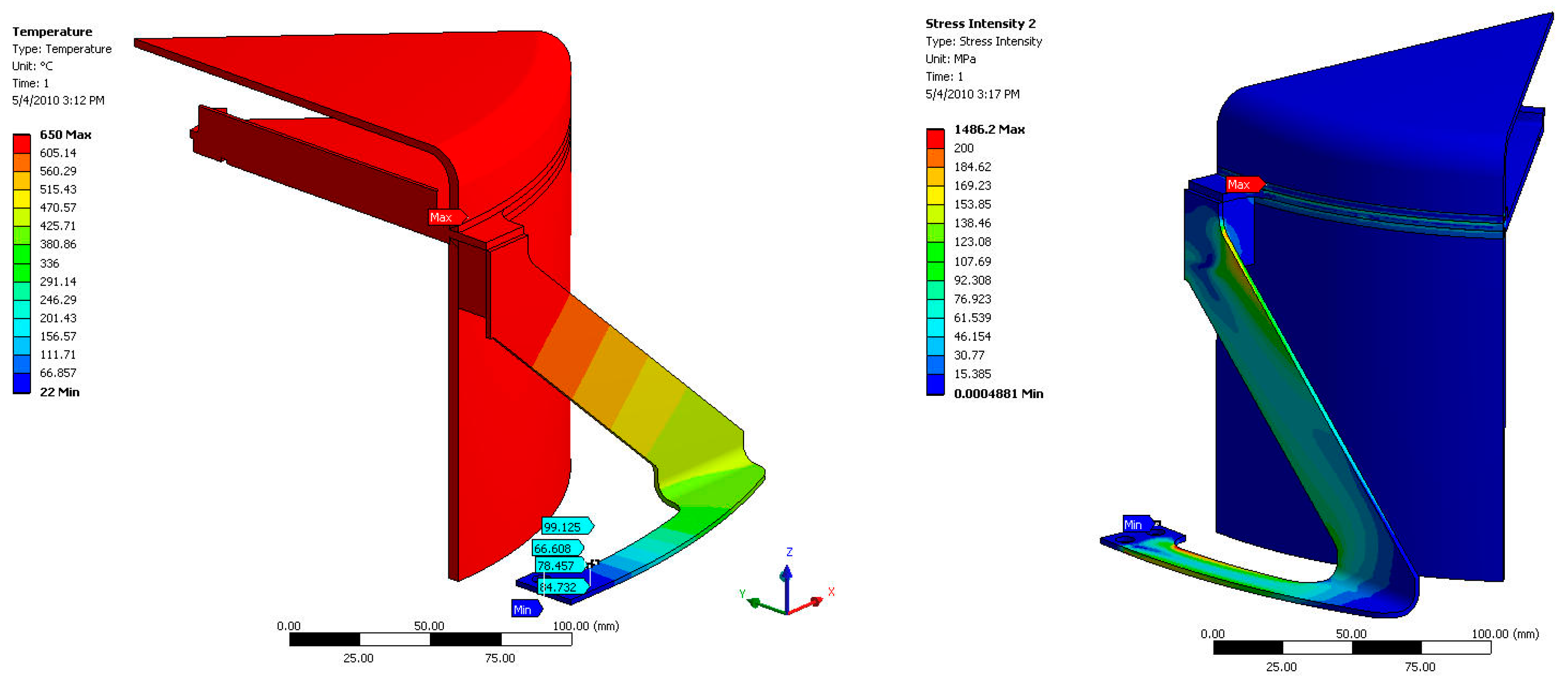
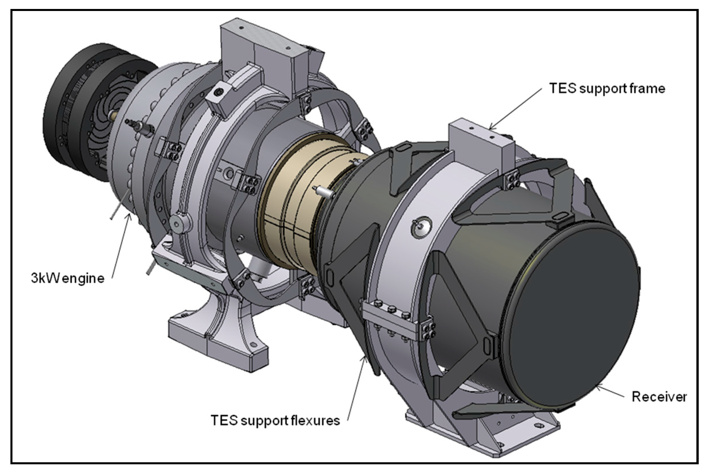
2.2. TES Module Support
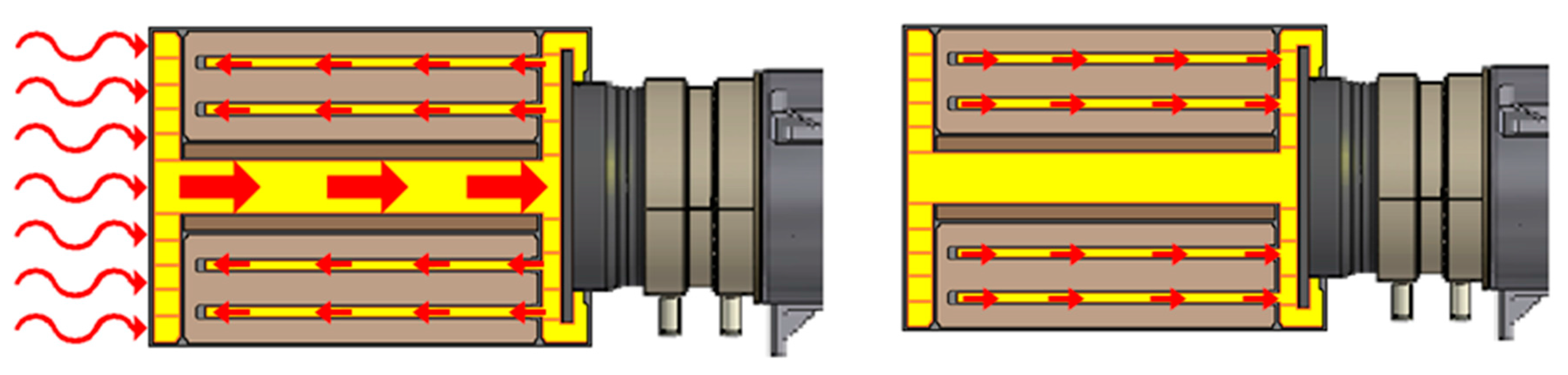
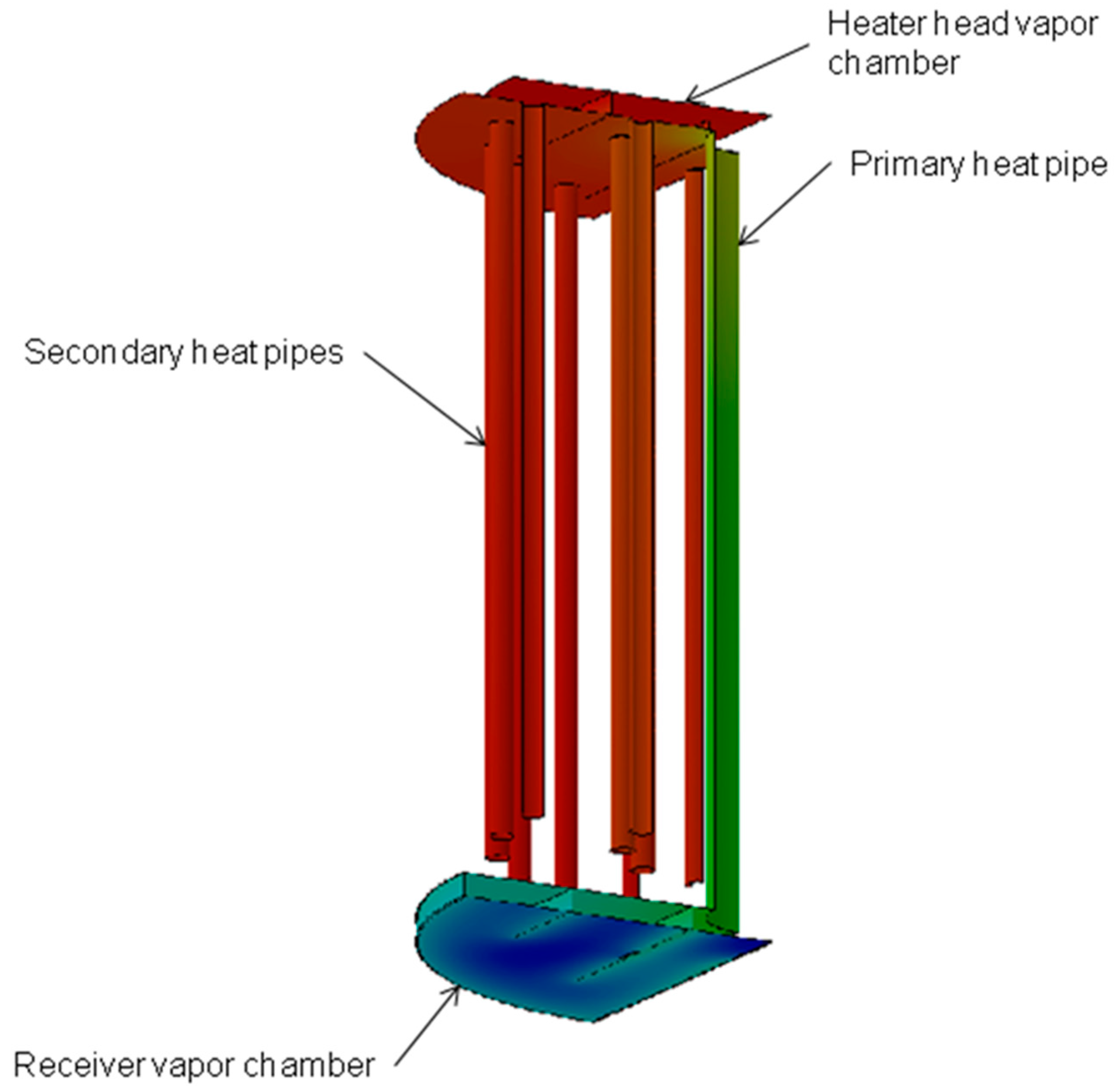
2.3. TES Module Design
3. LCOE Analysis
4. Testing of the Dish-Stirling TES CSP System
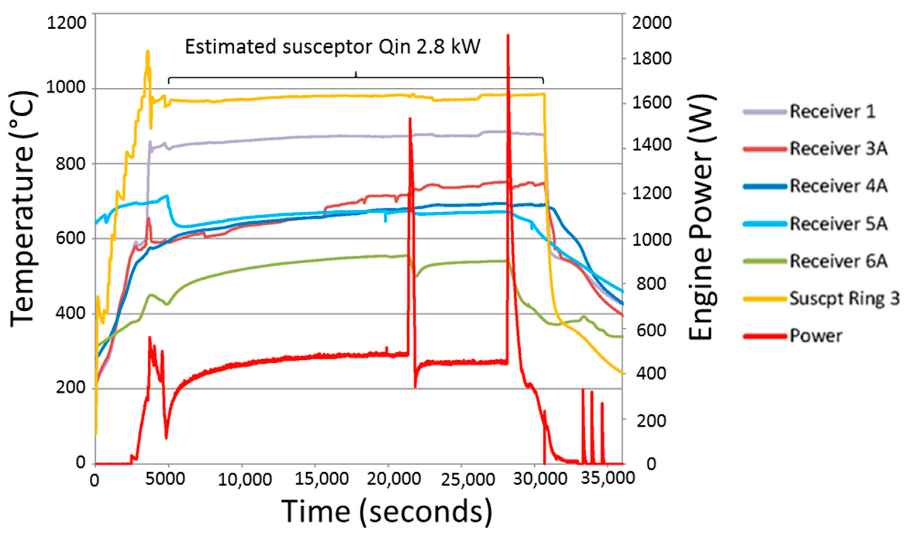
4.1. Gravity-Assisted Results
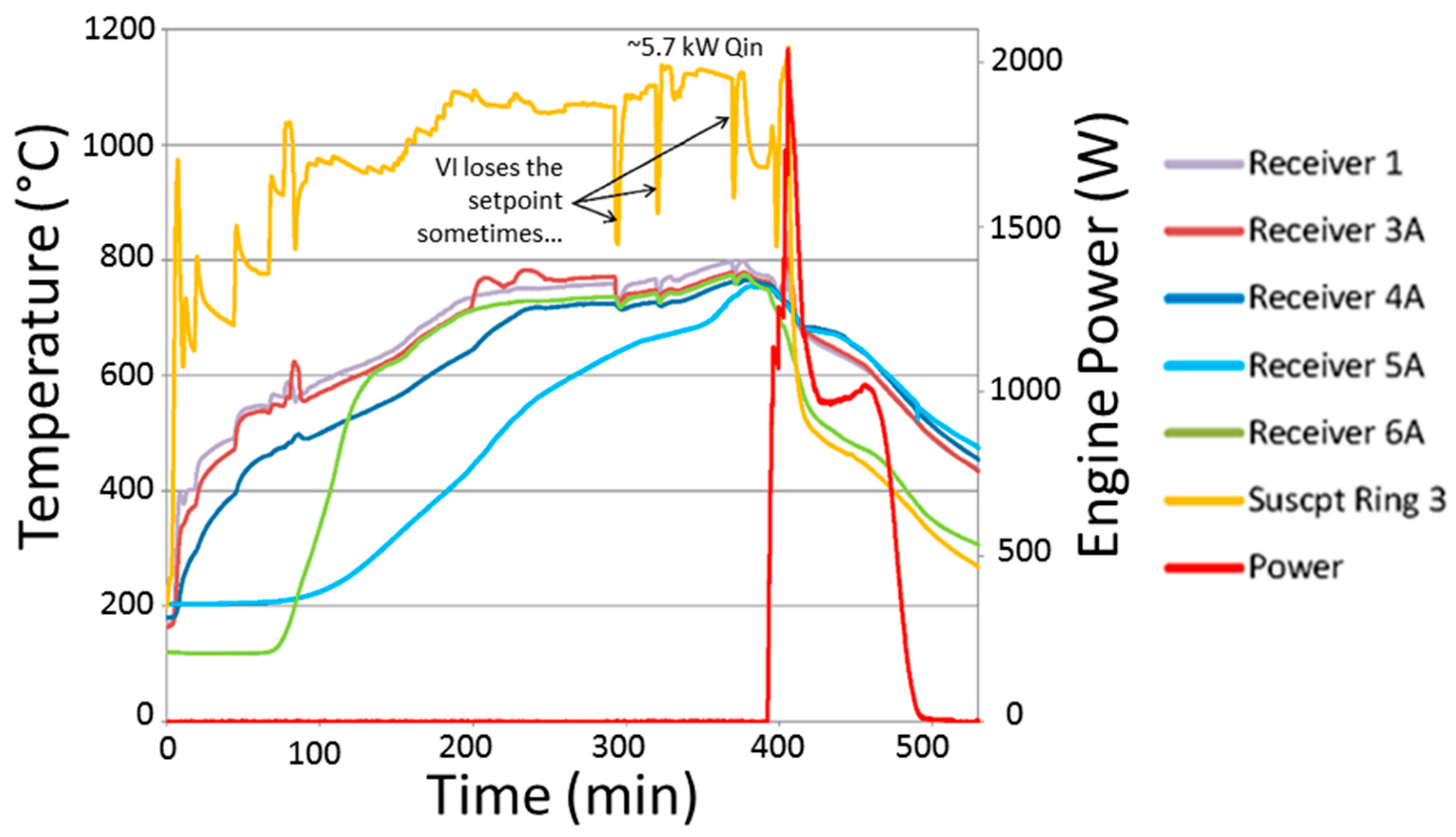
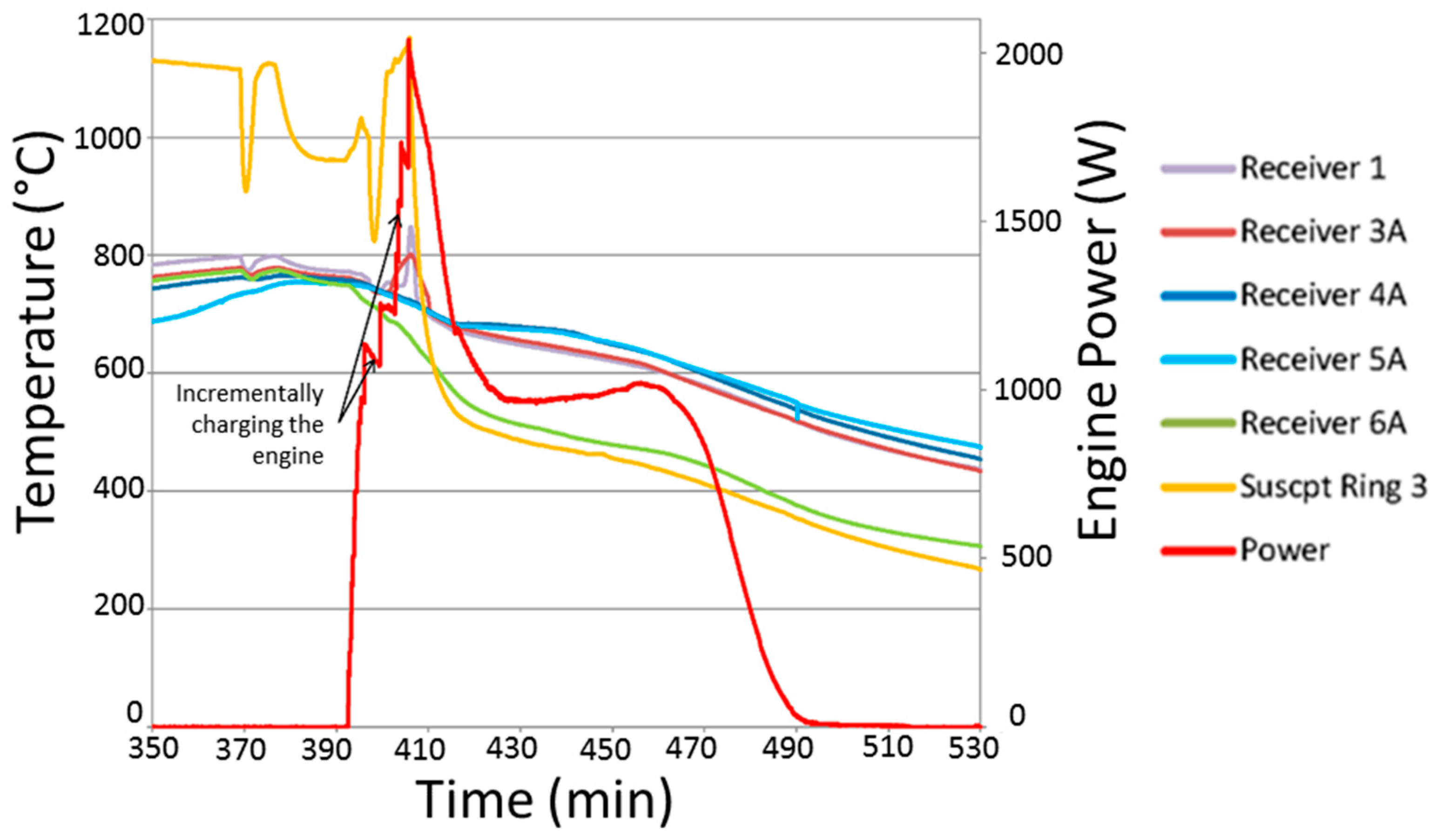
4.2. Horizontal Orientation Testing
5. Conclusions
Acknowledgments
Author Contributions
Conflicts of Interest
Nomenclature
| CSP | Concentrating solar power |
| HTF | Heat transfer fluid |
| PCM | Phase change material |
| TES | Thermal energy storage |
| LCOE | Levelized cost of energy |
References
- Herrmann, U.; Kearney, D.W. Survey of Thermal Energy Storage for Parabolic Trough Power Plants. J. Sol. Energy Eng. 2002, 124, 145–152. [Google Scholar] [CrossRef]
- Gil, A.; Medrano, M.; Martorell, I.; Lazaro, A.; Dolado, P.; Zalba, B.; Cabeza, L.F. State of the art on high temperature thermal energy storage for power generation. Part 1—Concepts, materials and modellization. Renew. Sustain. Energy Rev. 2010, 14, 31–55. [Google Scholar] [CrossRef]
- Kuravi, S.; Trahan, J.; Goswami, D.Y.; Rahman, M.M.; Stefanakos, E.K. Thermal energy storage technologies and systems for concentrating solar power plants. Prog. Energy Combust. Sci. 2013, 39, 285–319. [Google Scholar] [CrossRef]
- Stine, W.B.; Diver, R.B. A Compendium of Solar Dish/Stirling Technology; No. SAND93-7026; Sandia National Labs: Albuquerque, NM, USA, 1994. [Google Scholar]
- Zheng, Y.; Zhao, W.; Sabol, J.C.; Tuzla, K.; Neti, S.; Oztekin, A.; Chen, J.C. Encapsulated phase change materials for energy storage—Characterization by calorimetry. Sol. Energy 2013, 87, 117–126. [Google Scholar] [CrossRef]
- Zhao, W.; Zheng, Y.; Sabol, J.C.; Tuzla, K.; Neti, S.; Oztekin, A.; Chen, J.C. High temperature calorimetry and use of magnesium chloride for thermal energy storage. Renew. Energy 2013, 50, 988–993. [Google Scholar] [CrossRef]
- Solomon, L.; Oztekin, A.; Neti, S.; Jain, H.; Pfeifer, T.; Matyáš, J.; Balaya, P.; Singh, D.; Wei, J. Determination of Parameters for Improved Efficiency in Thermal Energy Storage Using Encapsulated Phase Change Materials. In Ceramics for Energy Conversion, Storage, and Distribution Systems; John Wiley & Sons, Inc.: New York, NY, USA, 2016; pp. 219–226. [Google Scholar]
- Singh, D.; Zhao, W.; Yu, W.; France, D.M.; Kim, T. Analysis of a graphite foam–NaCl latent heat storage system for supercritical CO2 power cycles for concentrated solar power. Sol. Energy 2015, 118, 232–242. [Google Scholar] [CrossRef]
- Thapa, S.; Chukwu, S.; Khaliq, A.; Weiss, L. Fabrication and analysis of small-scale thermal energy storage with conductivity enhancement. Energy Convers. Manag. 2014, 79, 161–170. [Google Scholar] [CrossRef]
- Almajali, M.; Lafdi, K.; Prodhomme, P.H. Effect of copper coating on infiltrated PCM/foam. Energy Convers. Manag. 2013, 66, 336–342. [Google Scholar] [CrossRef]
- Kim, T.; France, D.M.; Yu, W.; Zhao, W.; Singh, D. Heat transfer analysis of a latent heat thermal energy storage system using graphite foam for concentrated solar power. Sol. Energy 2014, 103, 438–447. [Google Scholar] [CrossRef]
- Zhao, C.Y.; Wu, Z.G. Heat transfer enhancement of high temperature thermal energy storage using metal foams and expanded graphite. Sol. Energy Mater. Sol. Cells 2011, 95, 636–643. [Google Scholar] [CrossRef]
- Baby, R.; Balaji, C. Experimental investigations on thermal performance enhancement and effect of orientation on porous matrix filled PCM based heat sink. Int. Commun. Heat Mass Transf. 2013, 46, 27–30. [Google Scholar] [CrossRef]
- Peiró, G.; Gasia, J.; Miró, L.; Cabeza, L.F. Experimental evaluation at pilot plant scale of multiple PCMs (cascaded) vs. single PCM configuration for thermal energy storage. Renew. Energy 2015, 83, 729–736. [Google Scholar] [CrossRef]
- Shabgard, H.; Robak, C.W.; Bergman, T.L.; Faghri, A. Heat transfer and exergy analysis of cascaded latent heat storage with gravity-assisted heat pipes for concentrating solar power applications. Sol. Energy 2012, 86, 816–830. [Google Scholar] [CrossRef]
- Solomon, L.; Oztekin, A. Exergy analysis of cascaded encapsulated phase change material—High-temperature thermal energy storage systems. J. Energy Storage 2016, 8, 12–26. [Google Scholar] [CrossRef]
- Alam, T.E.; Dhau, J.S.; Goswami, D.Y.; Stefanakos, E. Macroencapsulation and characterization of phase change materials for latent heat thermal energy storage systems. Appl. Energy 2015, 154, 92–101. [Google Scholar] [CrossRef]
- Jacob, R.; Bruno, F. Review on shell materials used in the encapsulation of phase change materials for high temperature thermal energy storage. Renew. Sustain. Energy Rev. 2015, 48, 79–87. [Google Scholar] [CrossRef]
- Xu, B.; Li, P.; Chan, C. Application of phase change materials for thermal energy storage in concentrated solar thermal power plants: A review to recent developments. Appl. Energy 2015, 160, 286–307. [Google Scholar] [CrossRef]
- Elmozughi, A.F.; Solomon, L.; Oztekin, A.; Neti, S. Encapsulated phase change material for high temperature thermal energy storage—Heat transfer analysis. Int. J. Heat Mass Transf. 2014, 78, 1135–1144. [Google Scholar] [CrossRef]
- Solomon, L.; Elmozughi, A.F.; Neti, S.; Oztekin, A. High Temperature Thermal Energy Storage Using EPCM: The Effect of Void. In Proceedings of the ASME 2014 International Mechanical Engineering Congress and Exposition, Montreal, QC, Canada, 14–20 November 2014; American Society of Mechanical Engineers: Montreal, QC, Canada, 2014. [Google Scholar]
- Solomon, L.; Elmozughi, A.F.; Oztekin, A.; Neti, S. Effect of internal void placement on the heat transfer performance–Encapsulated phase change material for energy storage. Renew. Energy 2015, 78, 438–447. [Google Scholar] [CrossRef]
- Solomon, L.; Oztekin, A. Encapsulated Phase Change Materials for use in High Temperature Thermal Energy Storage. In Advances in Energy Research; Acosta, M.J., Ed.; Nova Science Publishers Inc.: Hauppauge, NY, USA, 2016. [Google Scholar]
- Zhao, W.; Zheng, Y.; Sabol, J.C.; Oztekin, A.; Neti, S.; Tuzla, K.; Misiolek, W.M.; Chen, J.C. Heat Transfer Analysis for Thermal Energy Storage Using NaNO3 as Encapsulated Phase Change Material. In Proceedings of the ASME 2012 Heat Transfer Summer Conference collocated with the ASME 2012 Fluids Engineering Division Summer Meeting and the ASME 2012 10th International Conference on Nanochannels, Microchannels, and Minichannels, Rio Grande, PR, USA, 8–12 July 2012; pp. 241–248. [Google Scholar]
- Zheng, Y.; Barton, J.L.; Tuzla, K.; Chen, J.C.; Neti, S.; Oztekin, A.; Misiolek, W.Z. Experimental and computational study of thermal energy storage with encapsulated NaNO3 for high temperature applications. Sol. Energy 2015, 115, 180–194. [Google Scholar] [CrossRef]
- Liu, M.; Saman, W.; Bruno, F. Review on storage materials and thermal performance enhancement techniques for high temperature phase change thermal storage systems. Renew. Sustain. Energy Rev. 2012, 16, 2118–2132. [Google Scholar] [CrossRef]
- Sharifi, N.; Bergman, T.L.; Faghri, A. Enhancement of PCM melting in enclosures with horizontally-finned internal surfaces. Int. J. Heat Mass Transf. 2011, 54, 4182–4192. [Google Scholar] [CrossRef]
- Mat, S.; Al-Abidi, A.A.; Sopian, K.; Sulaiman, M.Y.; Mohammad, A.T. Enhance heat transfer for PCM melting in triplex tube with internal–external fins. Energy Convers. Manag. 2013, 74, 223–236. [Google Scholar] [CrossRef]
- Hosseini, M.J.; Ranjbar, A.A.; Rahimi, M.; Bahrampoury, R. Experimental and numerical evaluation of longitudinally finned latent heat thermal storage systems. Energy Build. 2015, 99, 263–272. [Google Scholar] [CrossRef]
- Shabgard, H.; Allen, M.J.; Sharifi, N.; Benn, S.P.; Faghri, A.; Bergman, T.L. Heat pipe heat exchangers and heat sinks: Opportunities, challenges, applications, analysis, and state of the art. Int. J. Heat Mass Transf. 2015, 89, 138–158. [Google Scholar] [CrossRef]
- Naghavi, M.S.; Ong, K.S.; Mehrali, M.; Badruddin, I.A.; Metselaar, H.S.C. A state-of-the-art review on hybrid heat pipe latent heat storage systems. Energy Convers. Manag. 2015, 105, 1178–1204. [Google Scholar] [CrossRef]
- Sharifi, N.; Wang, S.; Bergman, T.L.; Faghri, A. Heat pipe-assisted melting of a phase change material. Int. J. Heat Mass Transf. 2012, 55, 3458–3469. [Google Scholar] [CrossRef]
- Motahar, S.; Khodabandeh, R. Experimental study on the melting and solidification of a phase change material enhanced by heat pipe. Int. Commun. Heat Mass Transf. 2016, 73, 1–6. [Google Scholar] [CrossRef]
- Robak, C.W.; Bergman, T.L.; Faghri, A. Enhancement of latent heat energy storage using embedded heat pipes. Int. J. Heat Mass Transf. 2011, 54, 3476–3484. [Google Scholar] [CrossRef]
- Shabgard, H.; Bergman, T.L.; Sharifi, N.; Faghri, A. High temperature latent heat thermal energy storage using heat pipes. Int. J. Heat Mass Transf. 2010, 53, 2979–2988. [Google Scholar] [CrossRef]
- Tiari, S.; Qiu, S.; Mahdavi, M. Numerical study of finned heat pipe-assisted thermal energy storage system with high temperature phase change material. Energy Convers. Manag. 2015, 89, 833–842. [Google Scholar] [CrossRef]
- Tiari, S.; Qiu, S.; Mahdavi, M. Discharging process of a finned heat pipe–assisted thermal energy storage system with high temperature phase change material. Energy Convers. Manag. 2016, 118, 426–437. [Google Scholar] [CrossRef]
- Tiari, S.; Qiu, S. Three-dimensional simulation of high temperature latent heat thermal energy storage system assisted by finned heat pipes. Energy Convers. Manag. 2015, 105, 260–271. [Google Scholar] [CrossRef]
- Hays, A.; Borquist, E.; Bailey, D.; Wood, D.; Weiss, L. Small-Scale Thermal Energy Storage with Capillary Conductivity Enhancement. In Proceedings of the ASME 2016 10th International Conference on Energy Sustainability Collocated with the ASME 2016 Power Conference and the ASME 2016 14th International Conference on Fuel Cell Science, Engineering and Technology, Charlotte, NC, USA, 26–30 June 2016. [Google Scholar]
- Shabgard, H.; Faghri, A.; Bergman, T.L.; Andraka, C.E. Numerical Simulation of Heat Pipe-Assisted Latent Heat Thermal Energy Storage Unit for Dish-Stirling Systems. J. Sol. Energy Eng. 2013, 136, 021025. [Google Scholar] [CrossRef]
- Sharifi, N.; Faghri, A.; Bergman, T.L.; Andraka, C.E. Simulation of heat pipe-assisted latent heat thermal energy storage with simultaneous charging and discharging. Int. J. Heat Mass Transf. 2015, 80, 170–179. [Google Scholar] [CrossRef]
- Cui, H.; Wang, Z.; Guo, Y.; Xu, W.; Yuan, X. Thermal performance analysis on unit tube for heat pipe receiver. Sol. Energy 2006, 80, 875–882. [Google Scholar] [CrossRef]
- Mahdavi, M.; Qiu, S.; Tiari, S. Numerical investigation of hydrodynamics and thermal performance of a specially configured heat pipe for high-temperature thermal energy storage systems. Appl. Therm. Eng. 2015, 81, 325–337. [Google Scholar] [CrossRef]
- Mahdavi, M.; Qiu, S.; Tiari, S. Improvement of a novel heat pipe network designed for latent heat thermal energy storage systems. Appl. Therm. Eng. 2016, 108, 878–892. [Google Scholar] [CrossRef]
- Mahdavi, M.; Qiu, S. Mathematical modeling and analysis of steady state performance of a heat pipe network. Appl. Therm. Eng. 2015, 91, 556–573. [Google Scholar] [CrossRef]


| Parameter | Operating Condition |
|---|---|
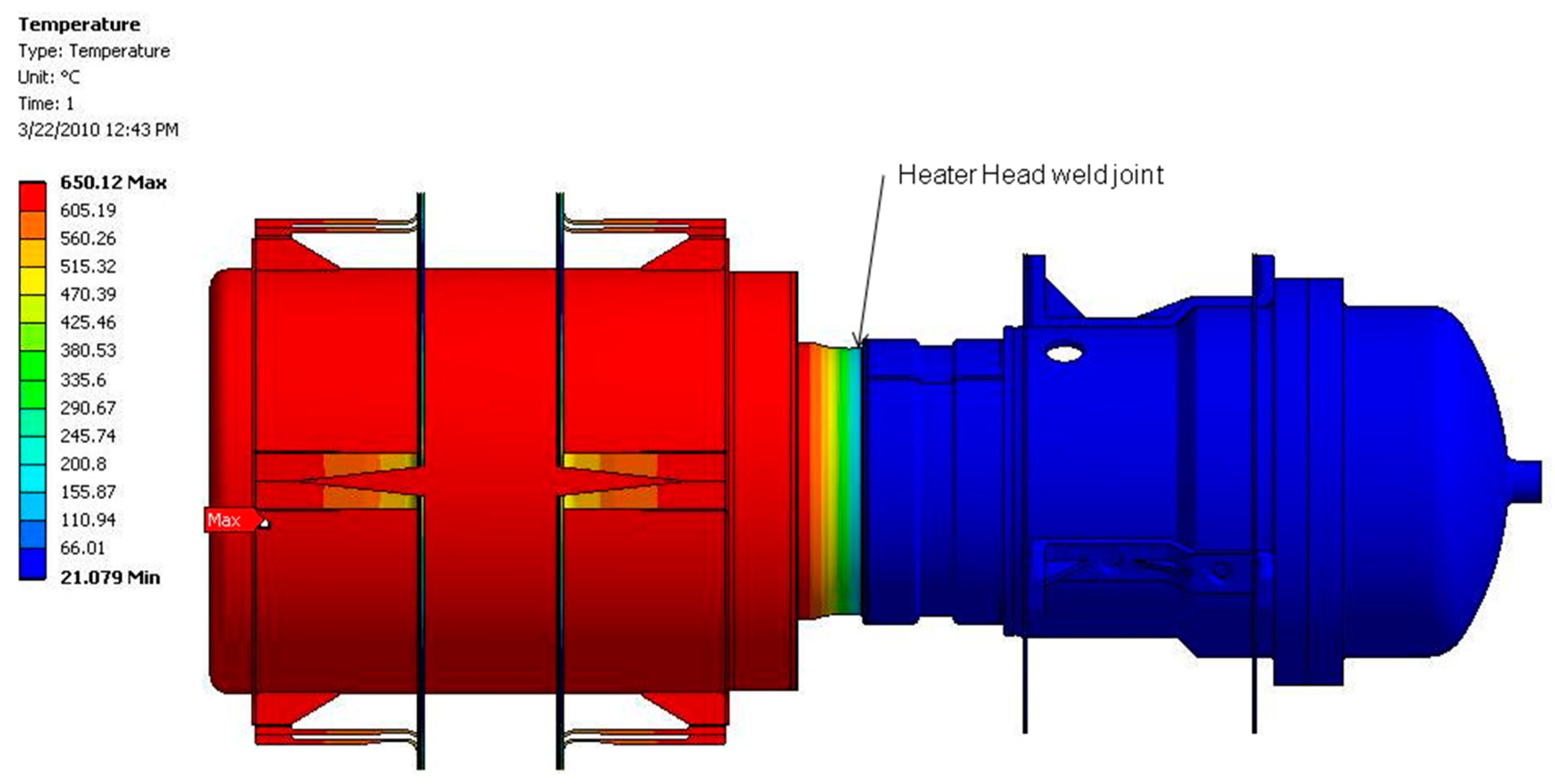
| Engine nominal operating temperature | 650 °C |
| Rejection temperature | 45 °C |
| Operation pressure (Engine) | 40 bar |
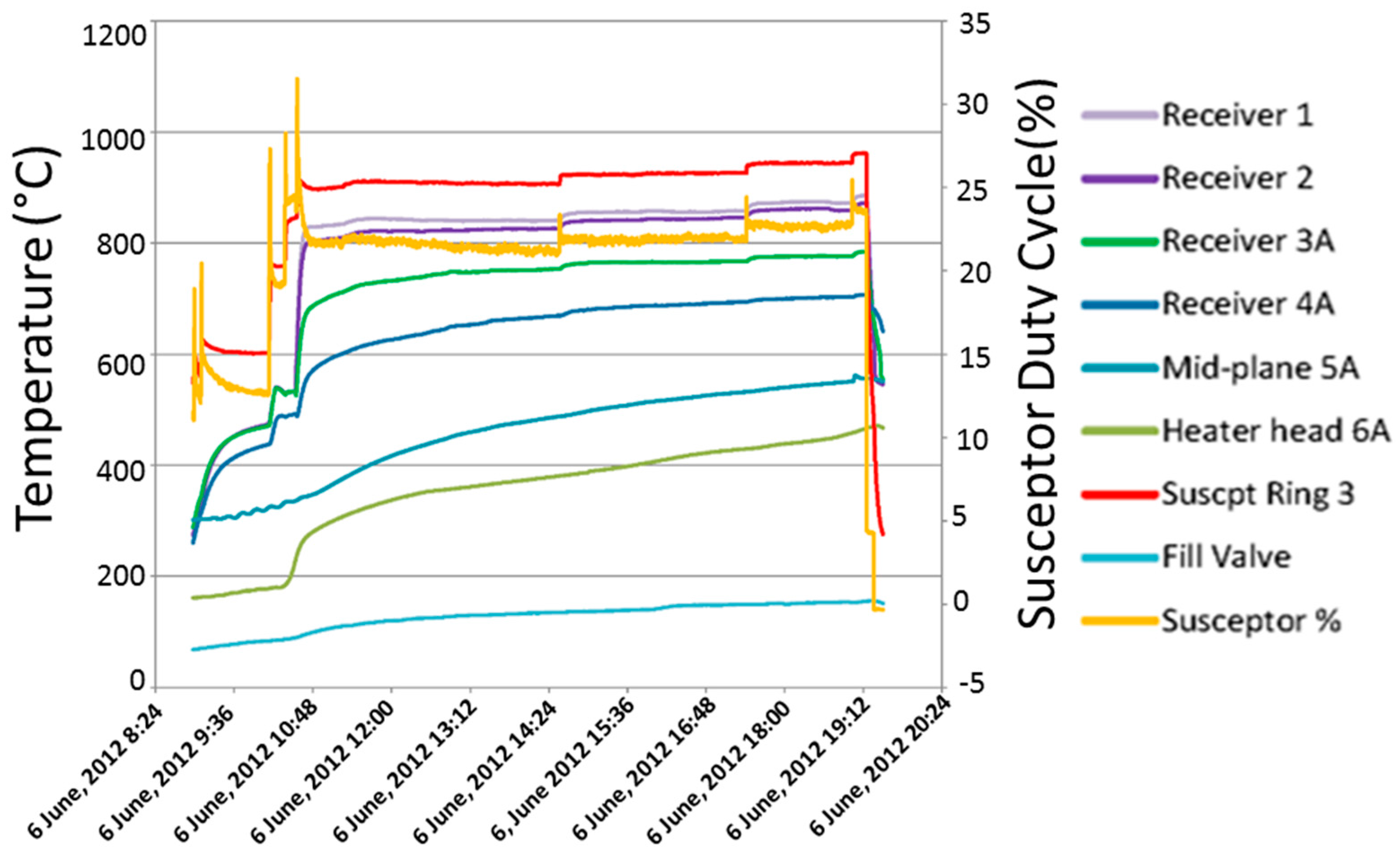
| TES testing temperature | 450–700 °C |
© 2017 by the authors. Licensee MDPI, Basel, Switzerland. This article is an open access article distributed under the terms and conditions of the Creative Commons Attribution (CC BY) license (http://creativecommons.org/licenses/by/4.0/).
Share and Cite
Qiu, S.; Solomon, L.; Rinker, G. Development of an Integrated Thermal Energy Storage and Free-Piston Stirling Generator for a Concentrating Solar Power System. Energies 2017, 10, 1361. https://doi.org/10.3390/en10091361
Qiu S, Solomon L, Rinker G. Development of an Integrated Thermal Energy Storage and Free-Piston Stirling Generator for a Concentrating Solar Power System. Energies. 2017; 10(9):1361. https://doi.org/10.3390/en10091361
Chicago/Turabian StyleQiu, Songgang, Laura Solomon, and Garrett Rinker. 2017. "Development of an Integrated Thermal Energy Storage and Free-Piston Stirling Generator for a Concentrating Solar Power System" Energies 10, no. 9: 1361. https://doi.org/10.3390/en10091361
APA StyleQiu, S., Solomon, L., & Rinker, G. (2017). Development of an Integrated Thermal Energy Storage and Free-Piston Stirling Generator for a Concentrating Solar Power System. Energies, 10(9), 1361. https://doi.org/10.3390/en10091361