Article

Permeability Change Caused by Stress Damage of Gas Shale

1
State Key Laboratory of Offshore Oil Exploitation, CNOOC Research Institute, Beijing 100028, China
2
School of Petroleum Engineering, China University of Petroleum (East China), Qingdao 266580, China
3
School of Mechanical Engineering, Yangtze University, Wuhan 430100, China
*
Authors to whom correspondence should be addressed.
Energies 2017, 10(9), 1350; https://doi.org/10.3390/en10091350
Submission received: 30 July 2017 / Revised: 23 August 2017 / Accepted: 31 August 2017 / Published: 6 September 2017
(This article belongs to the Special Issue Oil and Gas Engineering)

Abstract

:
Stress damage of shale during the uniaxial loading process will cause the change of permeability. The study of stress sensitivity of shale has focused on the influence of confining pressure on shale permeability and the change of shale permeability during the loading process of axial stress is lacking. The permeability of gas shale during loading process was tested. The results show that shale damage macroscopically reflects the process of axial micro-cracks generation and expansion, and the axial micro-cracks will cause permeability change during the loading process. There is a good corresponding relationship between damage development and micro-crack expansion during the process of shale loading. The damage factor will increase in the linear elastic stage and enlarge rapidly after entering the stage of unstable micro-crack expansion, and the permeability of shale increases with the increasing of shale damage. The research results provide a reliable test basis for further analysis of the borehole instability and hydraulic fracture mechanisms in shale gas reservoirs.

1. Introduction

As a typical representative of unconventional resources, shale gas is playing an important role in energy supply and has attracted increasing attention in recent years [1,2]. Take the United States as an example, a large amount of natural gas is produced from gas shale. Although the initial productivity is high for a shale gas well, the productivity declined steeply [3]. According to a survey from EIA (U.S. Energy Information Administration), 34% of natural gas produced in the United States is from gas shale in 2011 and that proportion will reach 45% in 2035 [2].
The main reason that shale gas reservoir is known as an “unconventional resource” is that it has very low porosity and very low permeability [4]. Pure use of traditional develop methods is difficult to obtain high productivity. Hydraulic fracturing is needed during the development of shale gas reservoirs [5] combined with CO2-enhanced oil recovery [6,7] and other new methods to increase the productivity. Meanwhile, borehole instability is an important problem restricting shale gas drilling [8,9,10]. Shale gas reservoirs generally have high strength and strong brittleness [11,12,13,14,15] and are a typical hard brittle shale. Borehole instability in such formations has not been effectively solved all the time [16,17,18], the borehole may still collapse with increasing borehole drilling time even though the pressure of the drilling fluid column is higher than the collapse pressure and the stress around the borehole is lower than the peak strength [16,19]. Rock under compression can undergo stress damage and create permeability variations even though the peak stress is not reached [20,21,22,23]. The damage characteristics of shale before the peak stress should be studied to determine mechanisms of borehole instability in shale gas reservoirs.
Extensive studies have been conducted on the correlation between damage of rock and stress loading [24,25,26]. They focused primarily on sandstone and marble and seldom on shale. The study on the relationship between stress and shale permeability mainly focuses on the influence of confining pressure on shale permeability [27], and the effect of stress damage caused by axial stress on permeability is lacking. Brittle rock exhibited axial splitting in the uniaxial compressive test [19,28,29,30,31] and the primary cause of failure is lateral damage from crack extension [32,33]. In this paper, the effect of stress damage on shale permeability was tested so as to provide a theoretical basis for analysis of the borehole instability and damage mechanisms in shale gas reservoirs and provide reference for studies on wellbore stability and hydraulic fracturing in shale gas reservoirs.

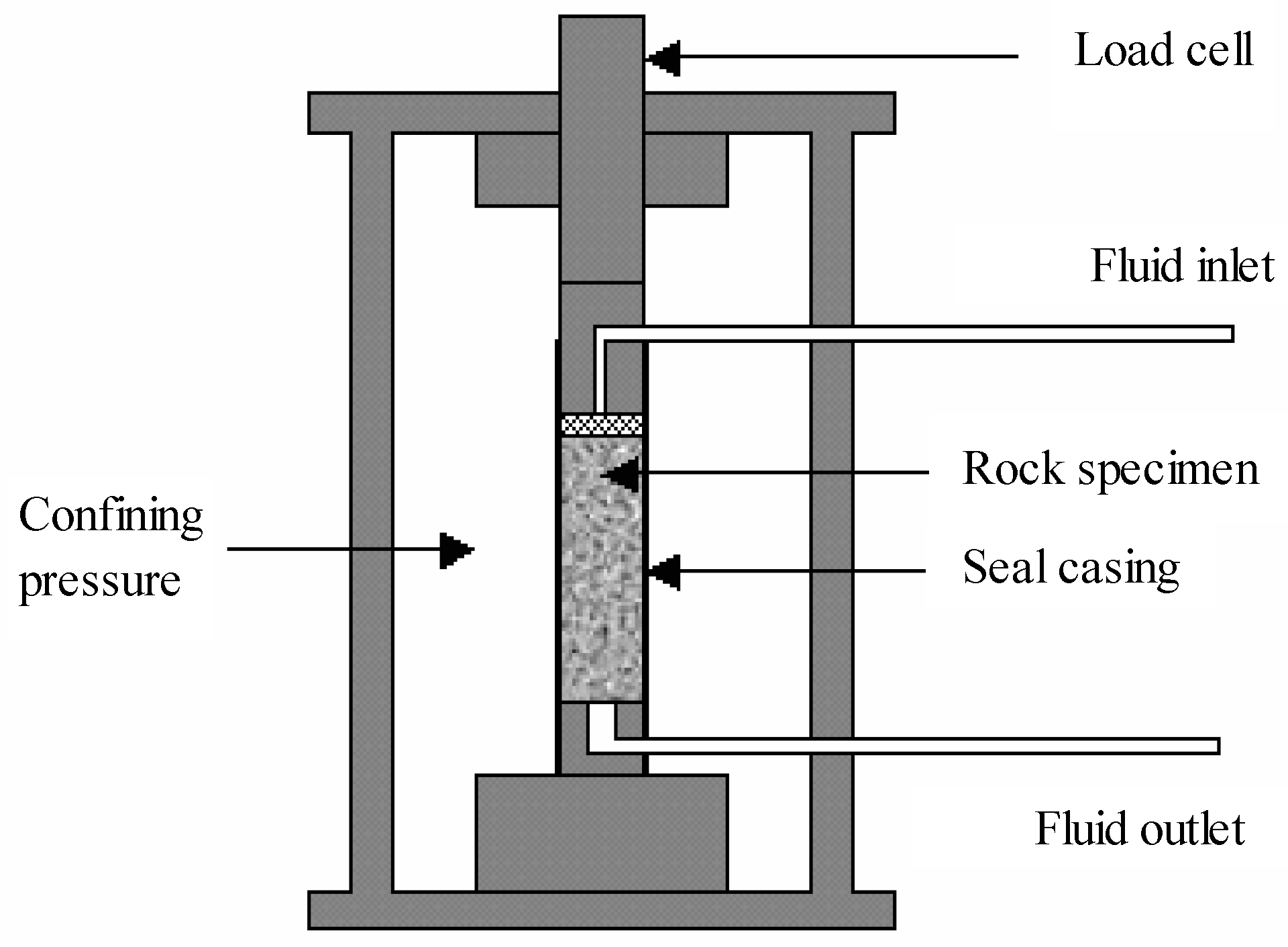
2. Experimental Scheme

Drilling of oil and gas wells can lead to redistribution of stress around the borehole and cause damage to rock around the borehole [34]. It is hard for any filter cake to form on the borehole wall and the rock of the borehole wall is approximately under uniaxial compression when drilling in shale [35], a formation with extremely low permeability. Therefore, it is crucial to study the evolution rule of shale damage and its effect on permeability under conditions of uniaxial compression.
In this test, the transient method [36] was used to determine variation of permeability of core under compression due to very low permeability of shale. Certain axial pressure, confining pressure, and pore pressure (lower than the confining pressure) were applied to the test specimen. Then certain differential pressure formed by maintaining the pore pressure of the upper end of the specimen and decreasing the pressure of the lower end. The differential pressure can cause fluid seepage within the shale. The permeability was indirectly determined by measuring the attenuation law of the differential pressure. Based on the data automatically acquired by the computer during the test, the rock permeability can be calculated as [36]
K = 1 5 n i = 1 n 526 × 10 6 × lg [ Δ p w ( i 1 ) Δ p w ( i ) ]
where, K is the permeability; n is the number of lines acquired and Δ p w ( i 1 ) and Δ p w ( i ) are the value of differential pressure of Line (i − 1) and Line i.
GCTS RTR-1500 Triaxial Rock Testing System (Beijing, China) was used in the test. Schematic diagram of the testing is shown in Figure 1. Loading was controlled by axial displacement of the sample and the loading rate was 0.002 mm/s; a 5 mm displacement sensor was used to measure axial deformation of the sample and a 1500 kN pressure sensor was used to measure the axial load; measurement accuracy of each measuring range was controlled within an error of 1%.
The shale samples used in this paper were cored from Sichuan Basin, China. After the core was removed from the site, it is immediately sent to the laboratory. The shale cores were processed into standard cylinder samples with length–diameter ratio of 1.8–2.0 in accordance with ISRM standard. Rock samples without macroscopic cracks were selected for test. Use abrasive paper to smooth the core end, and the core was dried in a dry oven for 24 h before conducting the permeability test. The information of the sample used in the permeability test is shown in Table 1.
The upper and lower indenter of the rock sample had a channel to allow the test fluid to pass through. The cores should be fully saturated before test. Unsaturation or insufficient saturation of the test specimen will lead to obstructed seepage and sometimes the seepage differential pressure does not fall purely (may rise locally) [36]. The test specimen of rock should be cylindrical and securely sealed during test to ensure osmosis only occur axially. The rock sample processed should be wrapped with thermoplastic rubber sleeves and placed in a high-pressure autoclave for test. The radial and axial displacement gauges are fixed to the surface of the wrapped sample to measure the deformation of the specimen during the test. The experiment was carried out at room temperature using nitrogen as the test fluid. Before the test, a confining pressure of 2 MPa was applied. At the same time we also applied a pore pressure of 1.7 MPa, always keep the confining pressure is greater than the pore pressure. During the permeability test, the pore pressure at one core end is reduced and the other end remained constant to measure the change of osmotic pressure difference with time.

3. Experimental Results

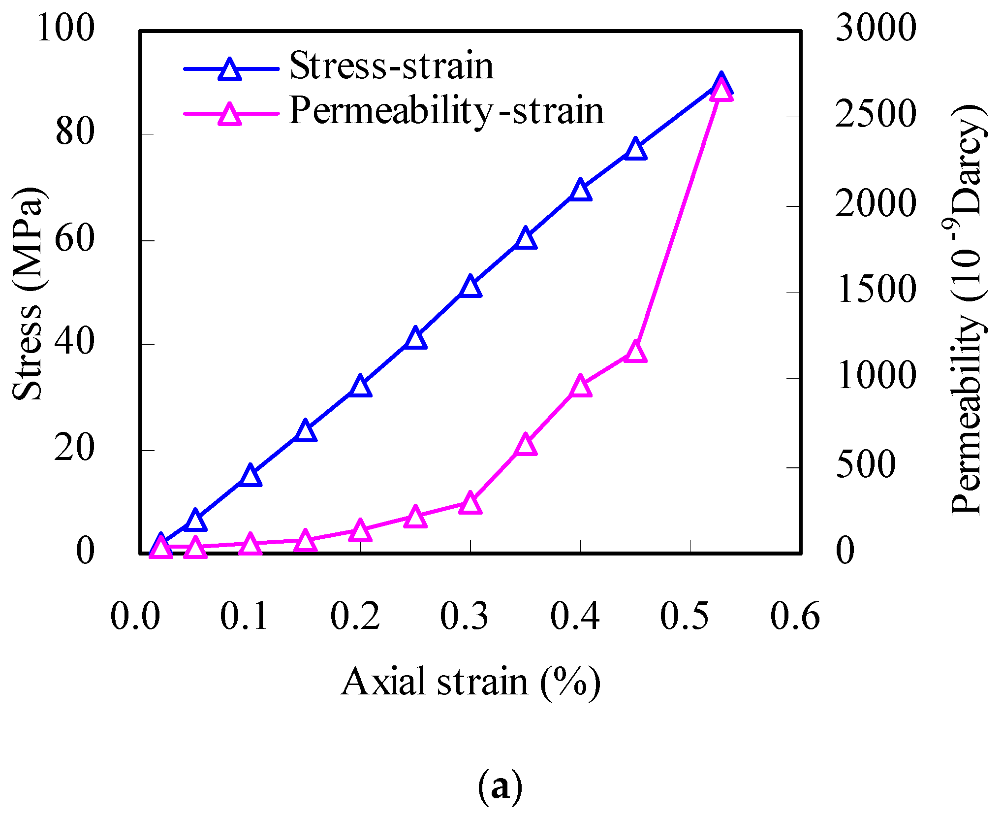
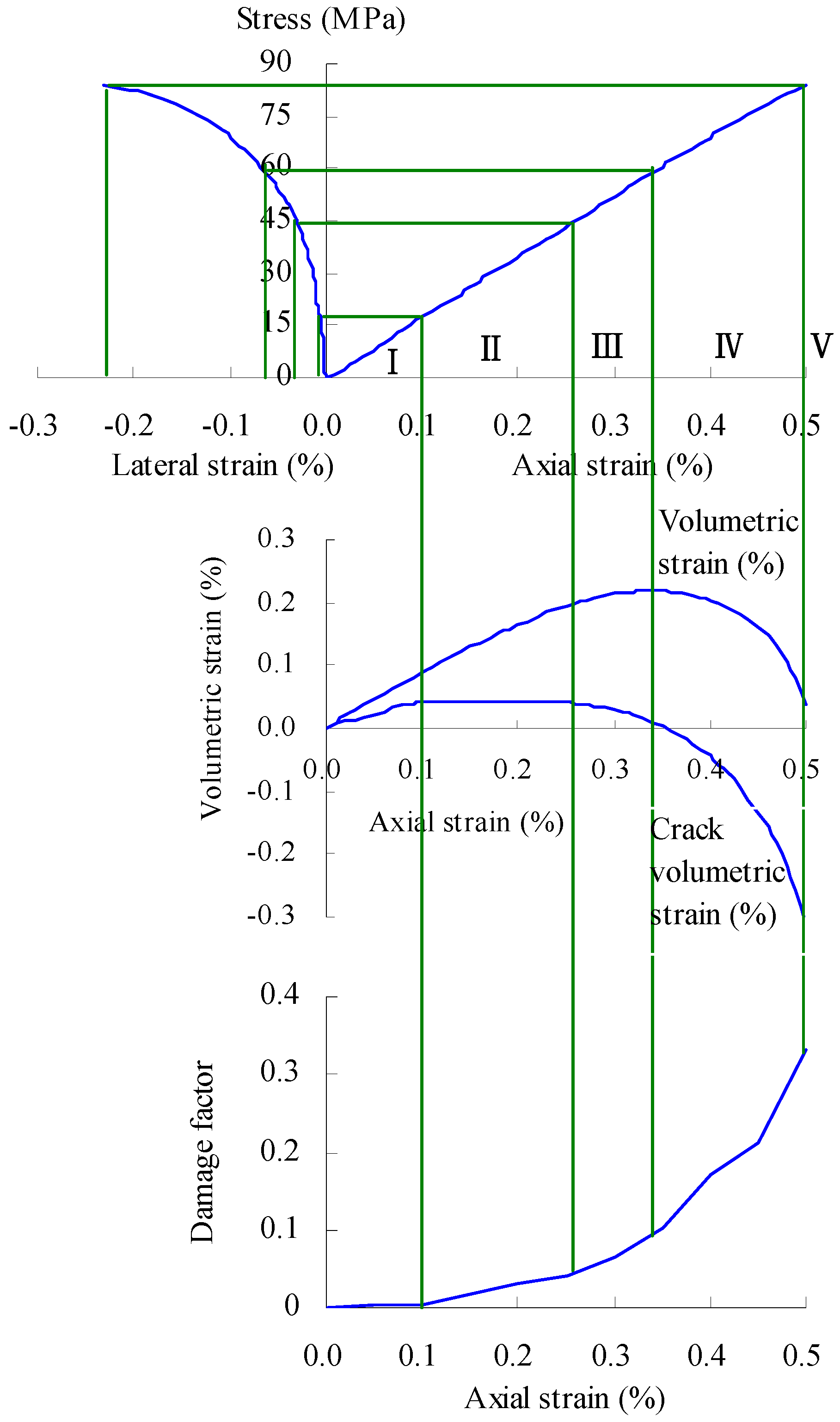
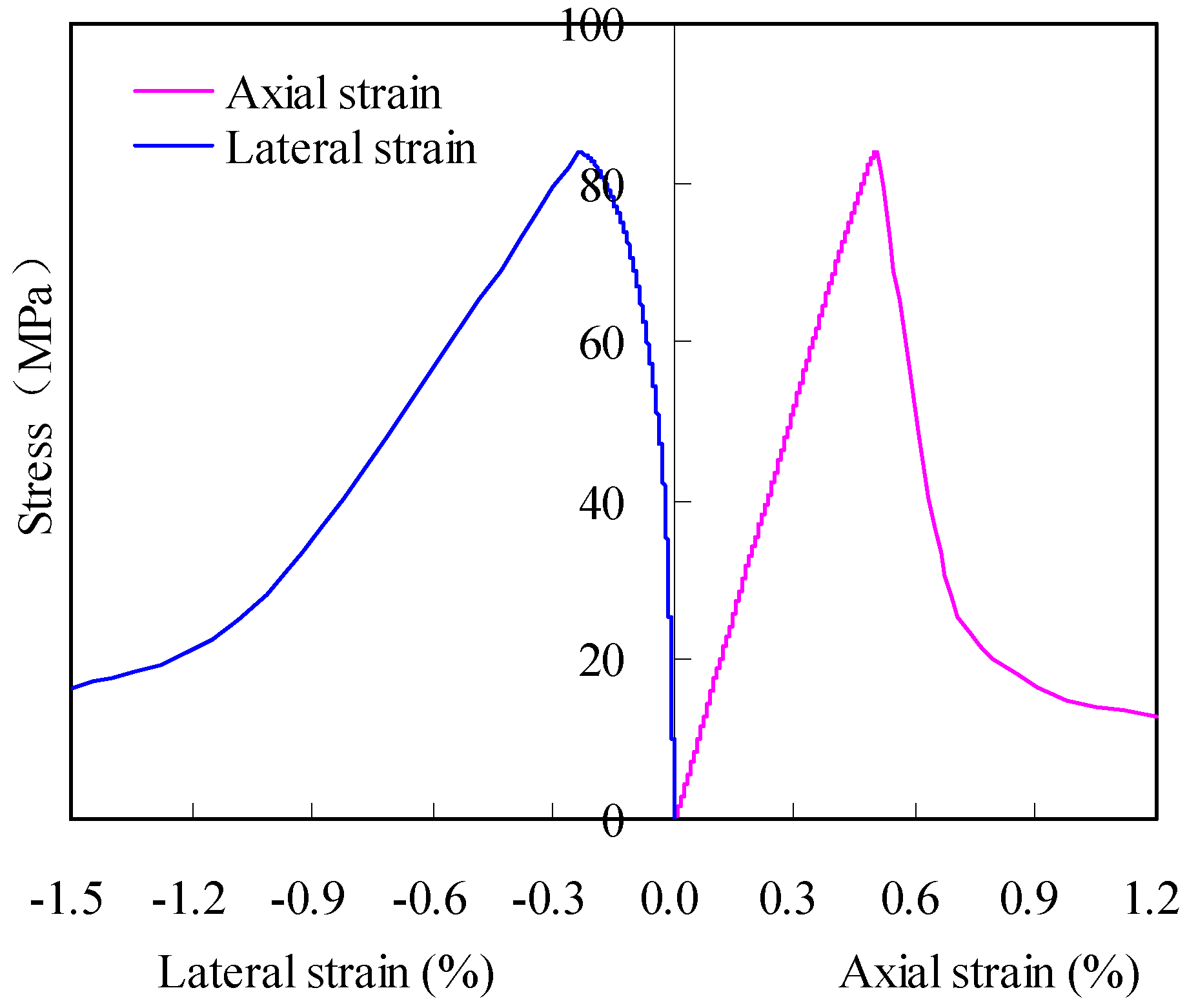
3.1. Total Stress–Strain Curve of Shale

Figure 2 shows the photographs for contrast of a sample before and after test. Figure 3 shows the total stress–strain curve for this core during uniaxial loading. It can be seen from the figures that axial strain was approximately 0.5% before failure and the failure mode was typical axial splitting with extremely strong brittleness. The sample lost bearing capacity quickly after failure. This paper studies the damage characteristics of shale before peak strength. During the permeability test, the confining pressure applied was 2 MPa and hardly influenced the damage mechanism of shale. The variation rule of the stress–strain curve is approximately the same as Figure 3.

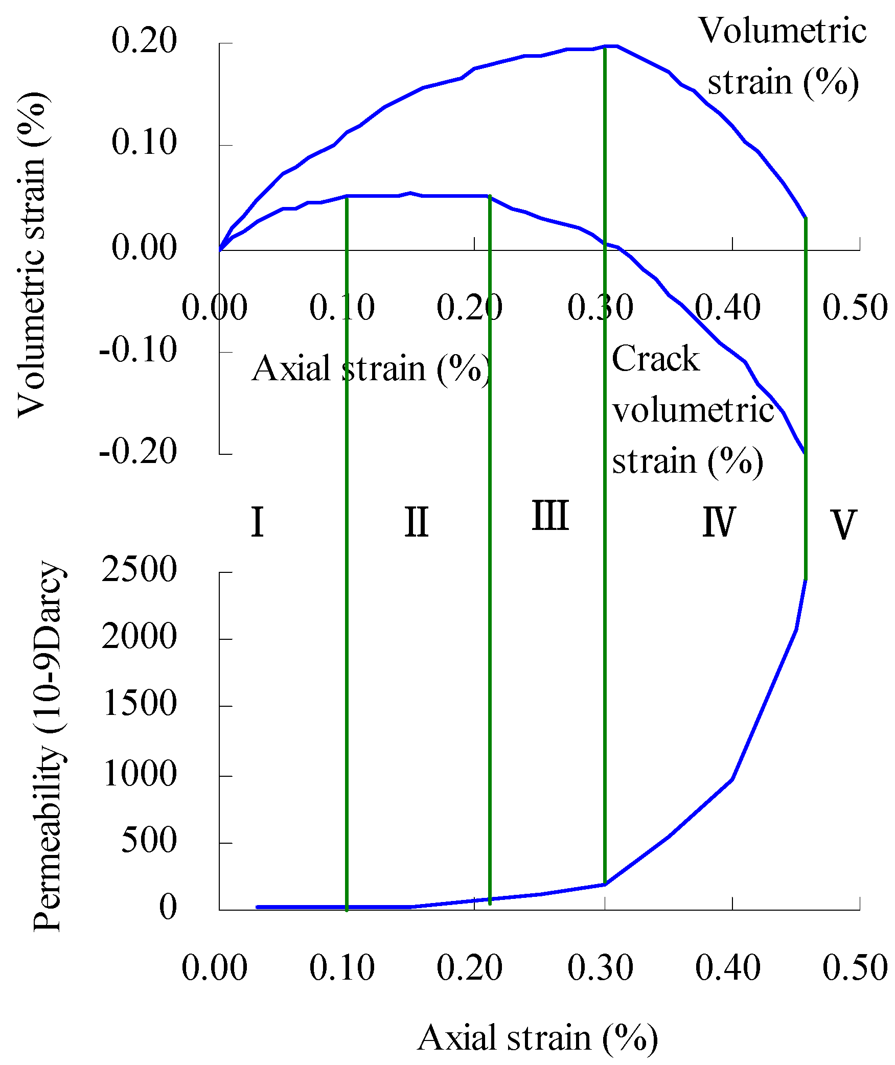
3.2. Permeability Variation during Shale Loading
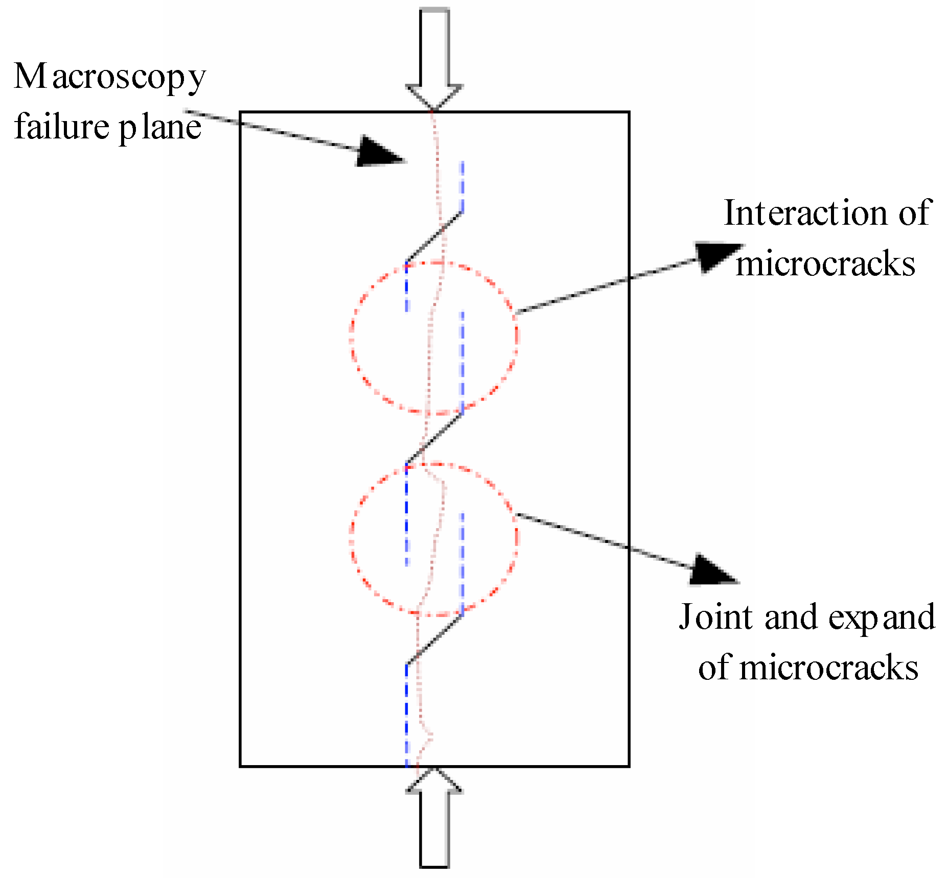
In this study, permeability variation of three shale samples during loading process was tested and the results are shown in Figure 4. The permeability remains unchanged basically during the initial stage of loading, and then increases gradually, reaching the maximum value at the peak strength. The maximum permeability can be up to more than 100 times the initial value.

4. Analysis

The uniaxial loading process for brittle rock can be divided into five stages [29,30,37], but it is difficult to distinguish among different stages of shale loading process based on the stress–strain curve shown in Figure 3. The essence of the damage in brittle rock is continuous expansion and accumulation of internal micro-cracks under high stress [32,33,38]. The loading process was divided by using volumetric strain and crack volumetric strain during loading. Crack volumetric strain can be calculated as [39]
ε c r v = ε v ε v e
ε v = ε 1 + 2 ε 3
ε v e = 1 2 v E σ a
where, ε c r v is crack volumetric strain, ε v is volumetric strain, ε v e is elastic volumetric strain, ε 1 is axial strain, ε 3 is lateral strain, and σ a is axial stress.
Shale can cause stress damage during loading process. The damage characteristics of shale can be analyzed based on the variations in the lateral p-wave velocity during compressive loading process. The relationship between p-wave velocity and damage factor is [19]
D = 1 ( V p / V f ) 2
where D is the damage factor, V p is the p-wave velocity, V f is the p-wave velocity in the complete (non-damaged) rock.
Based on the contrast of stress damage, permeability, and crack development process during loading process (Figure 5). Compared with the stress damage measured by lateral acoustic velocity (Figure 6) [19], it is discovered that the variation rules of damage factor and permeability are the same and perfectly consistent with crack development during different loading stages, which indicates that permeability variation closely relates to its damage evolution process.
Stage I: Crack closure. Internal micro-cracks develop in shale when shale is squeezed under high ground stress. Pre-existing cracks oriented at an angle to the applied stress close [38,40]. No obvious compaction process occurs in the lateral cracks due to the fact that the lateral cracks can expand and deform freely under uniaxial compression, enabling the lateral wave velocity to remain unchanged basically. The damage factors during this stage basically maintain their initial status and the permeability also remains unchanged basically.
Stage II: Linear elastic deformation. When the axial stress reaches approximately 15% of the peak strength, the damage factors of shale begins to increase, which indicates that new micro-cracks begin to form in shale. As partial initial cracks are still in their compression closure the total number of cracks remains unchanged basically, but the direction of new cracks are basically parallel to the direction of loading, which results in the increasing of axial permeability. Young’s modulus and Poisson’s ratio of shale can be calculated from this linear portion of the stress–strain curve [41].
Stage III: Stable fracture propagation. When axial stress reaches approximately 50% of the peak strength, closure of original cracks has already ended basically; new cracks are producing continuously and micro-cracks intersect; the volume of cracks is increasing slowly and the growth rate of damage factors and permeability increase compared with those in the previous stage.
Stage IV: Unstable fracture propagation. In this stage, volumetric dilatancy starts when the stress is approximately 70% of the peak strength. The damage factor increases rapidly and the core enters the rapid damage stage before failure. With increasing axial stress, the internal cracks further expand and intersect, macro-cracks emerge, complete seepage channels form, and the shale permeability increases sharply. It is worth noting that the axial acoustic velocity of shale also decreases in this stage, indicating intersection of cracks imposes an effect on the axial acoustic velocity.
Stage V: Failure and post-peak behavior. Unstable crack growth continues to the point where the numerous microcracks have coalesced and the rock can no longer support an increase in load [38]. In this paper, damage in this stage will not be studied.
Jones [42] and Zhou [43] have summarized the coupling relationship between permeability and stress of fractured rock mass and considered that the permeability coefficient of rock mass varies with the interaction relationship between stress and cracks; when the compaction effect results from stress, the permeability will fall with increasing stress; when the tensile effect results from stress, the permeability will increase with increasing stress. Failure of brittle rock is the result of initiation, expansion, and connection of cracks in medium. Based on studies by Zhou et al. [31], the expansion mode of cracks in brittle rock (Figure 7 [31]) is approximately axial under the condition of uniaxial loading. It coincides well with the failure mode of shale (Figure 2). Axial cracks of shale basically have no compaction process due to lack of lateral restraint or little restraint under the condition of uniaxial or low confining pressure (2 MPa in this test) and new cracks are producing and expanding constantly from the linear elastic stage. It coincides well with the variation rule of permeability measured in the test.
There are two types of pores in shale: the storage pores and the connecting pores (as shown in Figure 8), i.e.,
ϕ = ϕ p + ϕ t
where ϕ is the total pores of shale, ϕ p is the storage pores, ϕ t is the connecting pores.
The transport property of shale is controlled by the connecting pores, and we usually call the porosity of connecting pores as the effective porosity. Shale is such a type of rock, it has a relatively high total porosity but with very low permeability. The total porosity of some shale can be as high as 40% but also with very low permeability [44]. This is just because the connecting of pores is very poor in shale, i.e.,
ϕ t < < ϕ p
Therefore, the effective porosity of shale is very low, which causes low permeability. However, when the stress state change in brittle shale and caused stress damage, and micro-cracks are initiated, the storage pores will be connected by the cracks. Although the volume of new cracks is not big, it belongs to the connecting pores. This will cause the effective porosity to improve apparently, and the permeability of shale can be improved hundreds of times. Permeability improvement induced by stress damage in brittle shale cannot be ignored.
If the shale is only loaded with confining pressure without axial stress, the pores of shale will be composted under confining pressure, resulting in a decrease in the permeability of shale, which is commonly called stress sensitivity [27]. In the triaxial compressive experiments, if the axial stress is applied under high confining pressure, the failure mode is mainly shear failure, which is very different from the axial splitting under low confining pressure and uniaxial conditions, so the stress damage characteristics are different. The permeability of the shale under a high confining pressure will increase at the later stage of Stage IV, and the permeability is reduced before that [45], which is quite different from the experimental results under low confining pressure. Therefore, the stress damage characteristics of shale and the confining pressure have a great relationship.

5. Conclusions

(1)
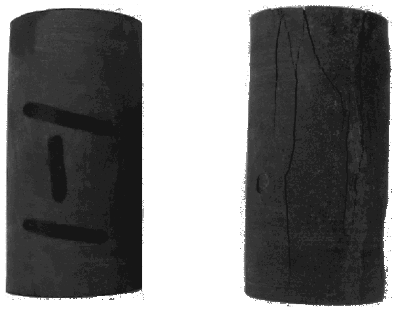
Under uniaxial or low confining pressure (2 MPa in this test) the failure mode of hard brittle shale is axial splitting resulting from expansion and intersection of axial cracks. There is nearly no damage in the preliminary stage of loading; new cracks emerge and damage factors increase in the linear elastic stage; micro-cracks intersect and damage factors increase rapidly in the stable development of cracks; damage increases sharply in the volumetric dilatancy stage and the core enters the rapid damage stage
(2)
Stress damage can lead to an increase in shale permeability and the variation rule of permeability is similar with that of the stress damage.
(3)
During drilling of a shale gas well, increasing permeability of shale will accelerate seepage of drilling fluid into the formation, leading to pore pressure increase, which causes shale hydration and—ultimately—borehole instability. To maintain borehole stability, the rapid damage stage after volumetric dilatancy of shale should be avoided as much as possible. Hydraulic fracturing of shale gas reservoirs requires a great deal of water and increasing permeability will increase seepage of fracturing fluid into the formation. This effect should be considered in the fracturing design.

Acknowledgments

This work is financially supported by the State Key Laboratory Program of Offshore Oil Exploitation, the Changjiang Scholars and Innovative Research Team in University (Grant No. IRT_14R58), the National Natural Science Foundation Project of China (Grant No. 51704311), the Qingdao National Laboratory for Marine Science and Technology (QNLM2016ORP0212), and the National Natural Science Foundation Project of China (Grant No. 51504040, 51574270, and 51504280).

Author Contributions

C.Y. and F.D. conceived and designed the experiments; C.Y. and F.D. performed the experiments; C.Y. and Y.C. analyzed the data; J.T. contributed reagents/materials/analysis tools; C.Y. wrote the paper.

Conflicts of Interest

The authors declare no conflict of interest.

References

  1. Zou, C.; Dong, D.; Wang, S.; Li, J.; Li, X.; Wang, Y.; Cheng, K. Geological characteristics and resource potential of shale gas in China. Pet. Explor. Dev. 2010, 37, 641–653. [Google Scholar] [CrossRef]
  2. Shen, W.; Li, X.; Xu, Y.; Sun, Y.; Huang, W. Gas Flow Behavior of Nanoscale Pores in Shale Gas Reservoirs. Energies 2017, 10, 751. [Google Scholar] [CrossRef]
  3. Wu, Y.; Li, X. Numerical simulation of the propagation of hydraulic and natural fracture using Dijkstra’s algorithm. Energies 2016, 9, 519. [Google Scholar] [CrossRef]
  4. Liu, H.; Ranjith, P.G.; Georgi, D.T.; Lai, B. Some key technical issues in modelling of gas transport process in shales: A review. Geomech. Geophys. Geo-Eng. Geo-Resour. 2016, 2, 231–243. [Google Scholar] [CrossRef]
  5. Li, X.; Feng, Z.; Han, G.; Elsworth, D.; Marone, C.; Saffer, D.; Cheon, D.-S. Breakdown pressure and fracture surface morphology of hydraulic fracturing in shale with H2O, CO2 and N2. Geomech. Geophys. Geo-Eng. Geo-Resour. 2016, 2, 63–76. [Google Scholar] [CrossRef]
  6. Patel, M.J.; May, E.F.; Johns, M.L. High-fidelity reservoir simulations of enhanced gas recovery with supercritical CO2. Energy 2016, 111, 548–559. [Google Scholar]
  7. Ampomah, W.; Balch, R.; Grigg, R.B.; Cather, M.; Gragg, E.; Will, R.A.; Dai, Z. Performance assessment of CO2-enhanced oil recovery and storage in the Morrow reservoir. Geomech. Geophys. Geo-Eng. Geo-Resour. 2017, 3, 245–263. [Google Scholar] [CrossRef]
  8. Meier, T.; Rybacki, E.; Backers, T.; Dresen, G. Influence of bedding angle on borehole stability: A laboratory investigation of transverse isotropic oil shale. Rock Mech. Rock Eng. 2015, 48, 1535–1546. [Google Scholar] [CrossRef]
  9. Yuan, J.; Deng, J.; Tan, Q.; Yu, B.; Jin, X. Borehole stability analysis of horizontal drilling in shale gas reservoirs. Rock Mech. Rock Eng. 2013, 46, 1157–1164. [Google Scholar] [CrossRef]
  10. Wu, Y.; Li, X.; He, J.; Zheng, B.; Sciubba, E. Mechanical properties of longmaxi black organic-rich shale samples from south china under uniaxial and triaxial compression states. Energies 2016, 9, 1088. [Google Scholar] [CrossRef]
  11. Sone, H.; Zoback, M.D. Mechanical properties of shale-gas reservoir rocks—Part 1: Static and dynamic elastic properties and anisotropy. Geophysics 2013, 78, 381–392. [Google Scholar] [CrossRef]
  12. Labani, M.M.; Rezaee, R. The importance of geochemical parameters and shale composition on rock mechanical properties of gas shale reservoirs: A case study from the Kockatea Shale and Carynginia Formation from the Perth Basin, Western Australia. Rock Mech. Rock Eng. 2015, 48, 1249–1257. [Google Scholar] [CrossRef]
  13. Heng, S.; Guo, Y.; Yang, C.; Daemen, J.J.; Li, Z. Experimental and theoretical study of the anisotropic properties of shale. Int. J. Rock. Mech. Min. Sci. 2015, 74, 58–68. [Google Scholar] [CrossRef]
  14. Yan, C.; Deng, J.; Cheng, Y.; Li, M.; Feng, Y.; Li, X. Mechanical Properties of Gas Shale During Drilling Operations. Rock Mech. Rock Eng. 2017, 50, 1753–1765. [Google Scholar] [CrossRef]
  15. Jin, Z.; Johnson, S.E. Effects of elastic anisotropy on primary petroleum migration through buoyancy-driven crack propagation. Geomech. Geophys. Geo-Eng. Geo-Resour. 2017, 1–14. [Google Scholar] [CrossRef]
  16. Yu, B.; Wang, Z.; Guo, B. Borehole Unstability Theory of Shale and Its Research Progress. Drill. Prod. Technol. 2007, 30, 16–21. [Google Scholar]
  17. Lora, R.V.; Ghazanfari, E.; Izquierdo, E.A. Geomechanical characterization of Marcellus shale. Rock Mech. Rock Eng. 2016, 49, 3403–3424. [Google Scholar] [CrossRef]
  18. Liu, M.; Jin, Y.; Lu, Y.; Chen, M.; Hou, B.; Chen, W.; Yu, X. A wellbore stability model for a deviated well in a transversely isotropic formation considering poroelastic effects. Rock Mech. Rock Eng. 2016, 49, 3671–3686. [Google Scholar] [CrossRef]
  19. Yan, C.; Deng, J.; Hu, L.; Chen, Z.; Yan, X.; Lin, H.; Tan, Q.; Yu, B. Brittle failure of shale under uniaxial compression. Arabian J. Geosci. 2015, 8, 2467–2475. [Google Scholar]
  20. Morrow, C.A.; Zhang, B.C.; Byerlee, J.D. Effective pressure law for permeability of Westerly granite under cyclic loading. J. Geophys. Res. Solid Earth 1986, 91, 3870–3876. [Google Scholar] [CrossRef]
  21. Ren, J.X.; Ge, X.R. Study of rock meso-damage evolution law and its constitutive model under uniaxial compression loading. Chin. J. Rock Mech. Eng. 2001, 20, 425–431. [Google Scholar]
  22. Wang, J.; Park, H.D. Fluid permeability of sedimentary rocks in a complete stress–strain process. Eng. Geol. 2002, 63, 291–300. [Google Scholar] [CrossRef]
  23. Kong, H.; Chen, Z.; Wang, L.; Shen, H. Experimental Study on Permeability of Crushed Gangues during Compaction. Int. J. Miner. Process. 2013, 124, 95–101. [Google Scholar] [CrossRef]
  24. Lu, J.; Lin, G.; Wang, Z. On the reduction of strength of concrete and supersonic inspection due to triaxial compressive loading history. Eng. Mech. 2002, 19, 52–57. [Google Scholar]
  25. Zhu, J.; Song, Y. Research on fatigue damage of concrete under biaxial compressive loading using ultrasonic velocity method. Chin. J. Rock Mech. Eng. 2004, 23, 2230–2234. [Google Scholar]
  26. Wang, H.; Song, Y. Ultrasonic pulses behaviour in various-size concrete specimens under compression. J. Dalian Univ. Technol. 2007, 47, 90–94. [Google Scholar]
  27. Tang, H.; Di, Y.; Zhang, Y.; Li, H. Impact of Stress-Dependent Matrix and Fracture Properties on Shale Gas Production. Energies 2017, 10, 996. [Google Scholar] [CrossRef]
  28. Brace, W.F. State of Stress in the Earth’s Crust. In Proceedings of the International Conference, Santa Monica, CA, USA, 13–14 June 1963. [Google Scholar]
  29. Eberhardt, E.; Stead, D.; Stimpson, B. Quantifying progressive pre-peak brittle fracture damage in rock during uniaxial compression. Int. J. Rock Mech. Min. Sci. 1999, 36, 361–380. [Google Scholar] [CrossRef]
  30. Eberhardt, E.; Stead, D.; Stimpson, B. Effects of grain size on the initiation and propagation thresholds of stress-induced brittle fractures. Rock Mech. Rock Eng. 1999, 32, 81–99. [Google Scholar] [CrossRef]
  31. Zhou, J.; Yang, X.; Fu, W. Experimental test and fracture damage mechanical characteristics of brittle rock under uniaxial cyclic loading and unloading conditions. Chin. J. Rock Mech. Eng. 2010, 29, 1172–1183. [Google Scholar]
  32. Bobet, A.; Einstein, H.H. Fracture coalescence in rock-type materials under uniaxial and biaxial compression. Int. J. Rock Mech. Min. Sci. 1998, 35, 863–888. [Google Scholar] [CrossRef]
  33. Zhu, Z.; Sheng, Q.; Zhang, Z. Study on lateral deformational characteristics and damage mechanism of brittle rock. Rock Soil Mech. 2008, 29, 2137–2143. [Google Scholar]
  34. Shao, J.; Khazraei, R. Wellbore stability analysis in brittle rocks with continuous damage model. In Proceedings of the SPE/ISRM Rock Mechanics in Petroleum Engineering Conference, Delft, The Netherlands, 29–31 August 1994. [Google Scholar]
  35. Dusseault, M.B.; Gray, K.E. Mechanisms of stress-induced wellbore damage. In Proceedings of the SPE Formation Damage Control Symposium, Lafayette, LA, USA, 26–27 February 1992. [Google Scholar]
  36. Yang, Y.; Song, Y.; Chen, S. Test study on permeability properties of coal specimen in complete stress–strain process. Rock Soil Mech. 2007, 28, 381–385. [Google Scholar]
  37. Jia, L.; Chen, M.; Zhang, W.; Xu, T.; Zhou, Y.; Hou, B.; Jin, Y. Experimental study and Numerical Modeling of Brittle Fracture of Carbonate Rock under Uniaxial Compression. Mech. Res. Commun. 2013, 50, 58–62. [Google Scholar] [CrossRef]
  38. Eberhardt, E. Brittle Rock Fracture and Progressive Damage in Uniaxial Compression. Ph.D. Thesis, University of Saskatchewan, Saskatoon, Canada, April 1998. [Google Scholar]
  39. Hidalgo, K.P.; Carlsson, B.; Nordlund, E. Identifying deformation parameters governing failure of hard rock: A laboratory test study. In Proceedings of the 2009 International Symposium on Rock Mechanics: “Rock Characterisation, Modelling and Engineering Design Methods”, Hong Kong, China, 19–22 May 2009. [Google Scholar]
  40. Bieniawski, Z.T. Mechanism of brittle rock fracture, Part II: Experimental studies. Int. J. Rock Mech. Min. Sci. Geomech. Abstr. 1967, 4, 395–406. [Google Scholar] [CrossRef]
  41. Martin, C.D.; Chandler, N.A. The progressive fracture of Lac du Bonnet granite. Int. J. Rock Mech. Min. Sci. Geomech. Abstr. 1994, 31, 643–659. [Google Scholar] [CrossRef]
  42. Jones, F. A laboratory study of the effects of confining pressure on fracture flow and storage capacity in carbonate rock. J. Pet. Technol. 1975, 27, 21–27. [Google Scholar] [CrossRef]
  43. Zhou, W. Advanced Rock Mechanics; Water Resources and Electric Power Press: Beijing, China, 1990. [Google Scholar]
  44. Jia, S. Hydro-Mechanical Coupled Creep Damage Constitutive Model of Boom Clay, Back Analysis of Model Parameters and Its Engineering Application. Ph.D. Thesis, Wuhan Institute of Rock & Soil Mechanics, Chinese Academy of Sciences, Wuhan, China, June 2009. [Google Scholar]
  45. Sun, W.; Zuo, Y.; Wu, Z.; Xu, Y. Experimental study on seepage-damage evolution of shale. China Min. Mag. 2017, 26, 142–145. [Google Scholar]
Figure 1. Schematic diagram for GCTS RTR-1500 Triaxial Rock Testing System.
Energies 10 01350 g001
Figure 2. Contrast between shale samples before and after test.
Energies 10 01350 g002
Figure 3. Uniaxial stress–strain curve.
Energies 10 01350 g003
Figure 4. Permeability of shale during loading. (a) Core 1; (b) Core 2; (c) Core 3.
Energies 10 01350 g004aEnergies 10 01350 g004b
Figure 5. Analysis on rules of permeability variation during shale loading.
Energies 10 01350 g005
Figure 6. Analysis of stress damage in shale [19].
Energies 10 01350 g006
Figure 7. Expansion mode of micro-crack in brittle rock.
Energies 10 01350 g007
Figure 8. Basic pore types in shale.
Energies 10 01350 g008
Table 1. Shale sample used in permeability test
Core No.Porosity (%)Quartz Content (%)Clay Mineral Content (%)
1434.639.8
2637.145.2
3541.240.3

