
Control Structures Evaluation for a Salt Extractive Distillation Pilot Plant: Application to Bio-Ethanol Dehydration

 ,
,  ,
, 
Abstract
:1. Introduction
2. Salt Extractive Distillation Process
2.1. Simulation Methodology
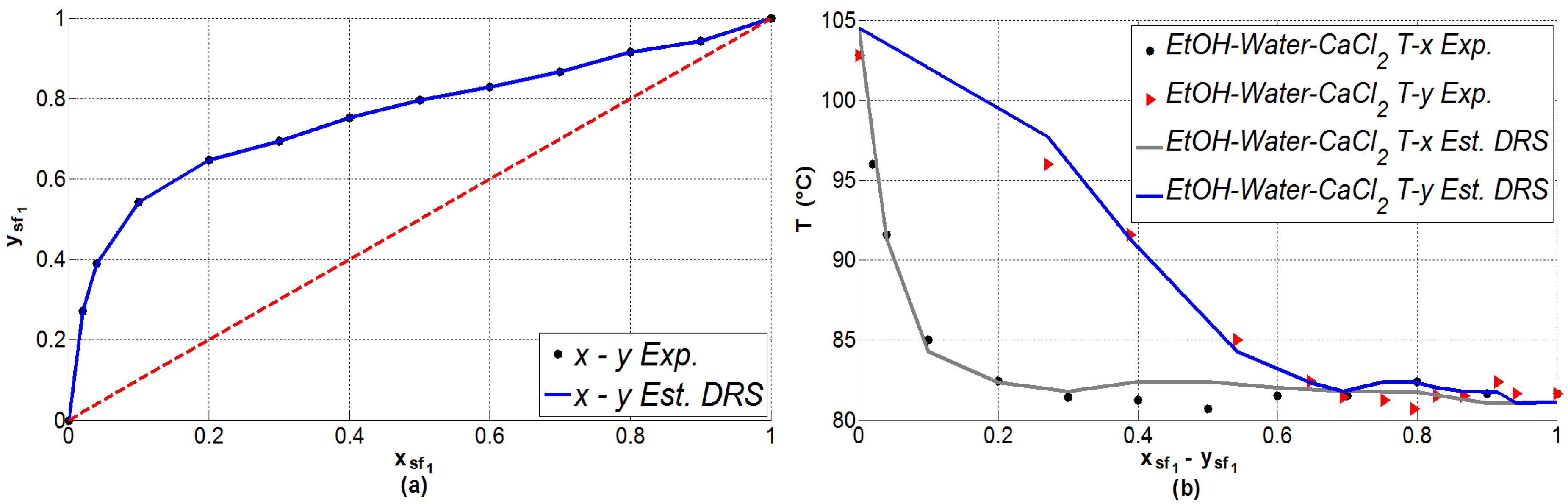
2.2. Vapor–Liquid Equilibrium Prediction
- The true mole fractions with . Equation (5) defining the composition of the quaternary system: ethanol[1]-water[2]-Ca[3]-Cl[4]:
- The apparent mole fractions or stoichiometric fractions with . Equation (6) defining the composition of the ternary system: ethanol[1]-water[2]-CaCl[3]:
- Or, on a salt-free basis mole fractions defining a pseudo-binary mixture: ethanol/CaCl[1]–water/CaCl[2]. Herein, with are the liquid phase salt-free mole fraction corresponding to the vapor phase mole fraction of ethanol and the vapor phase mole fraction of water . The salt concentration is calculated as indicated in Equation (7):where , and are the molecular weights of the ethanol (46.07 /), water (18.02 /) and CaCl (110.99 /), respectively, and is the molecular weight of the binary mixture Equation (8).
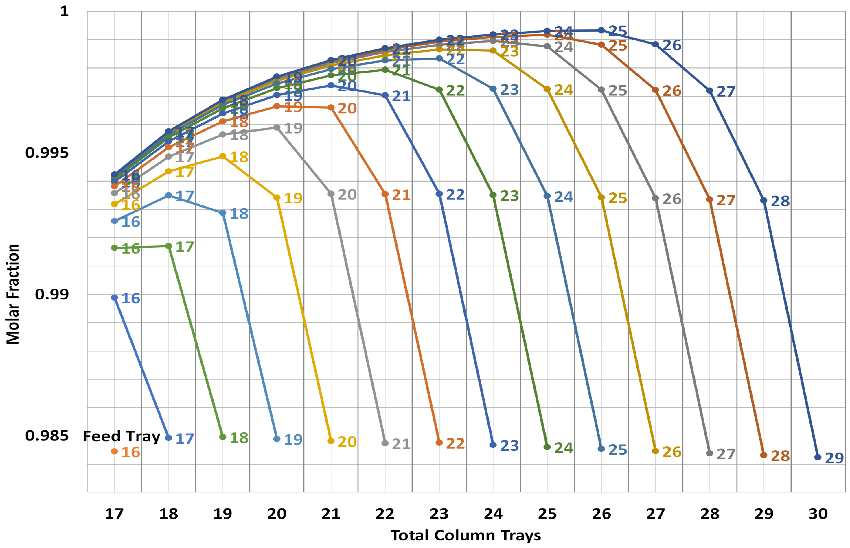
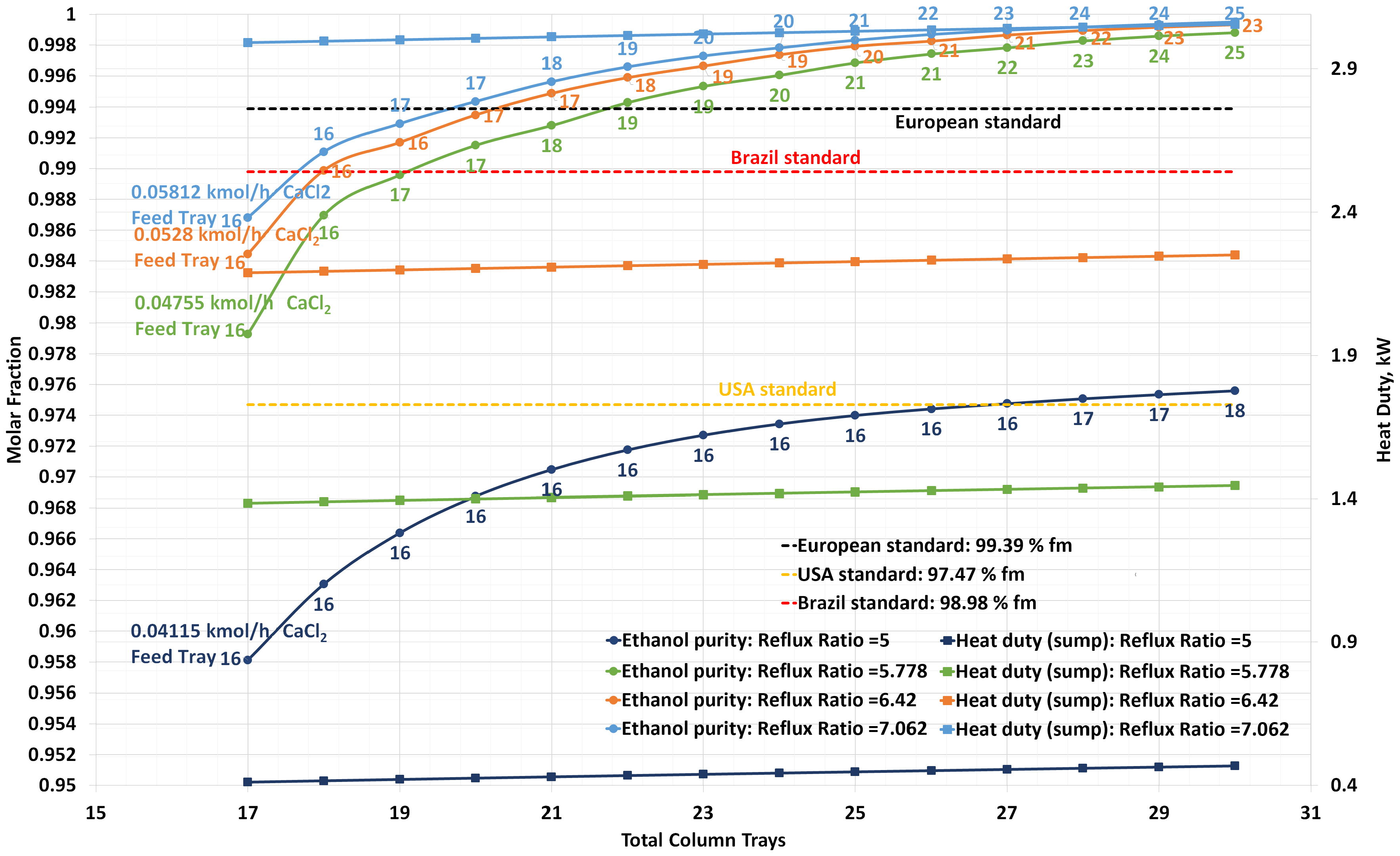
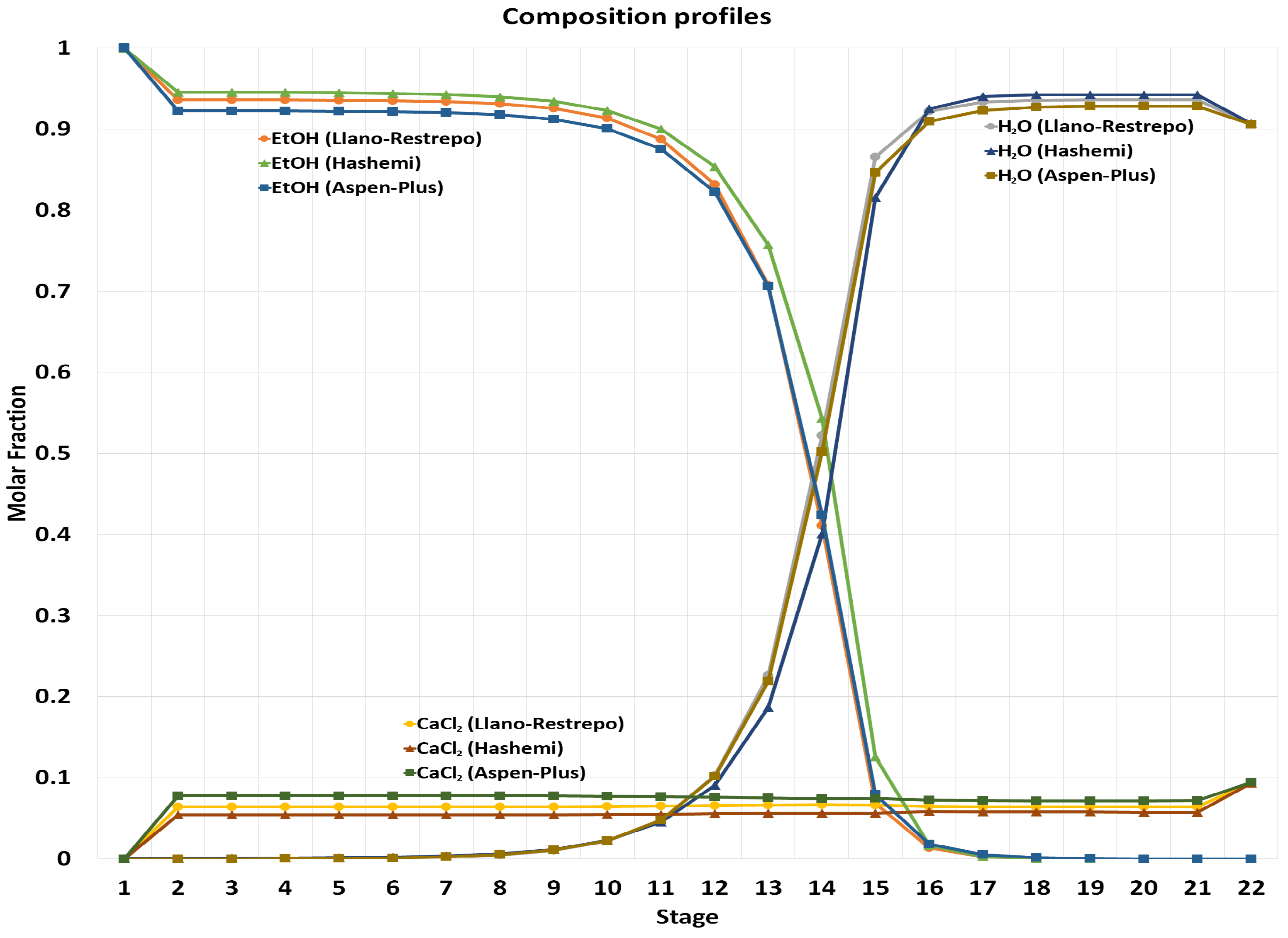
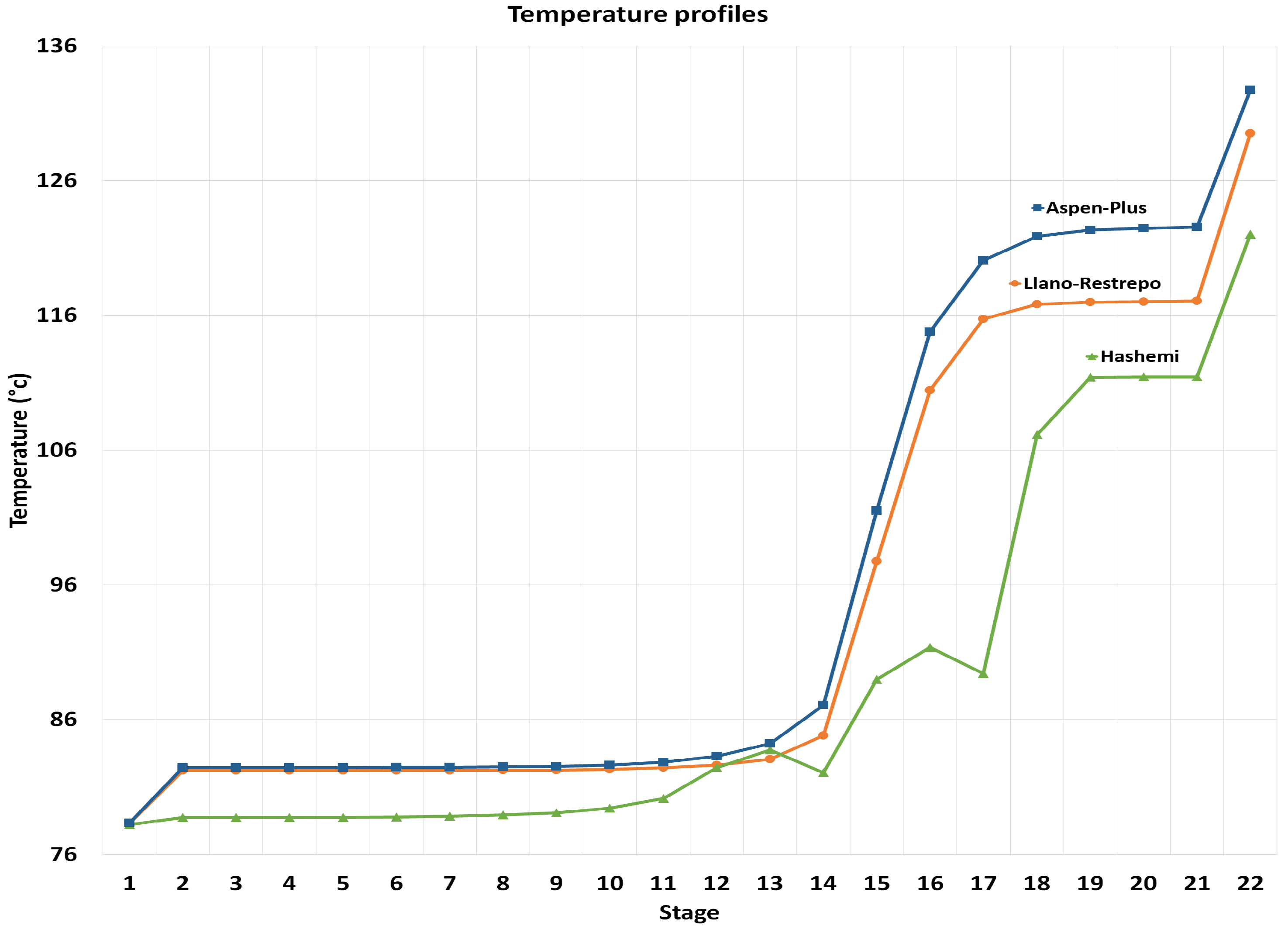
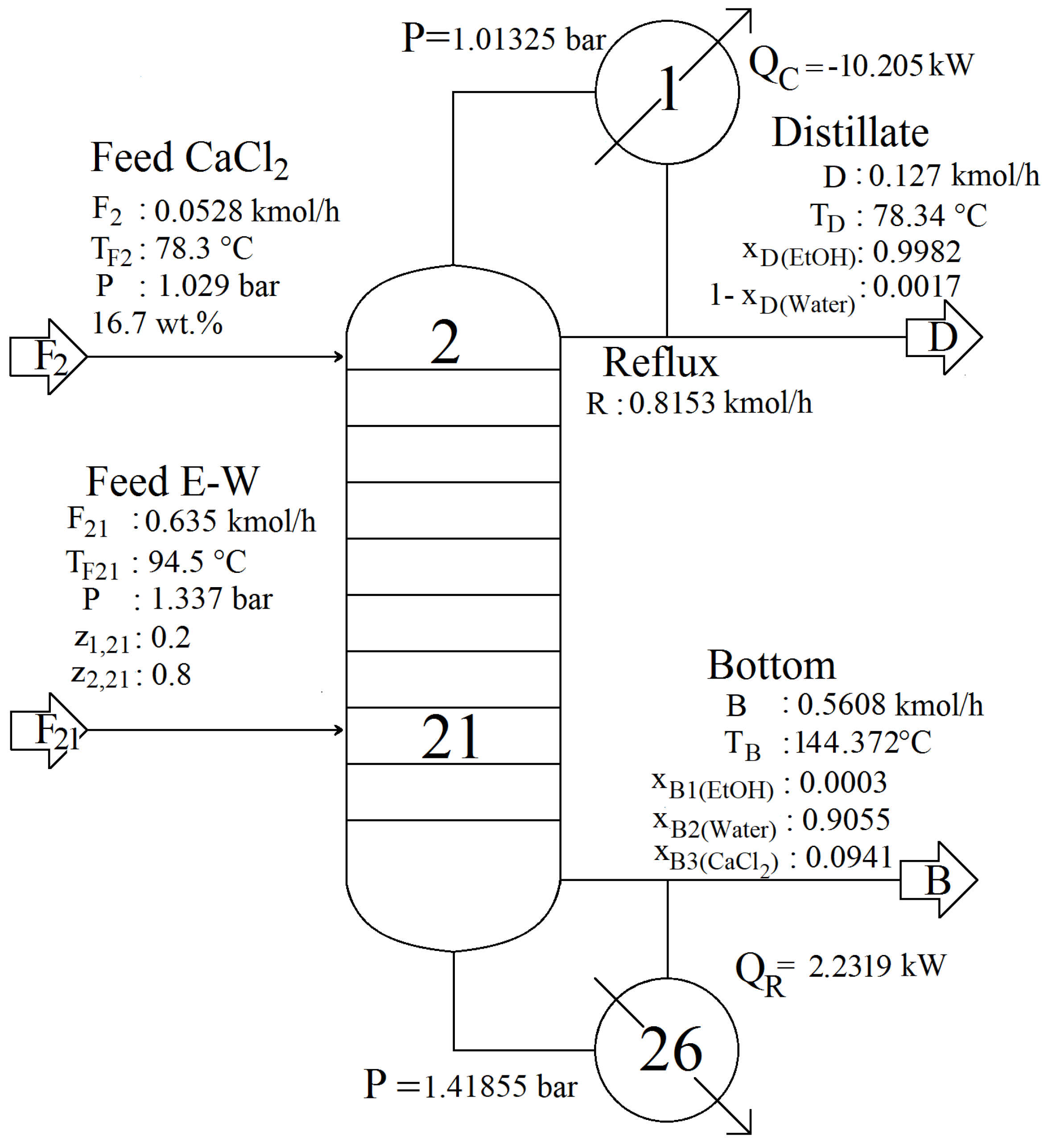
2.3. Steady-State Design
3. Control Structures
- A nonlinear thermodynamic model is used for non-ideal VLE prediction of an electrolytic system.
- The ethanol–water–CaCl system is considered as a pseudo-binary mixture and apparent compositions are handled along with the distillation column conservation equations.
- An additional input current is introduced at the top of the column with the dissolved salt.
- A further degree of freedom is imposed by the addition of the salt, but it is assumed as an ideal control loop with the objective of adjusting the salt feeding flow as a function of the main feed, the products and the reflux change, in order to conserve a salt composition close to 16.7 wt % on a salt-free basis throughout the columns’ trays.
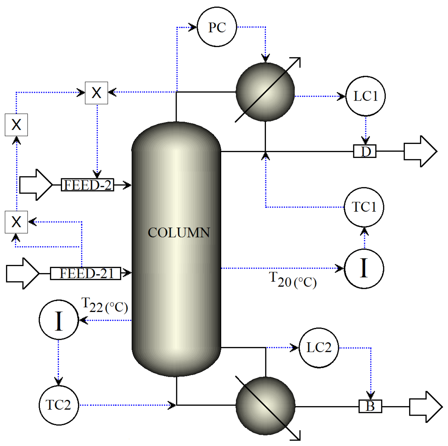
3.1. Dual Temperature Control Structure
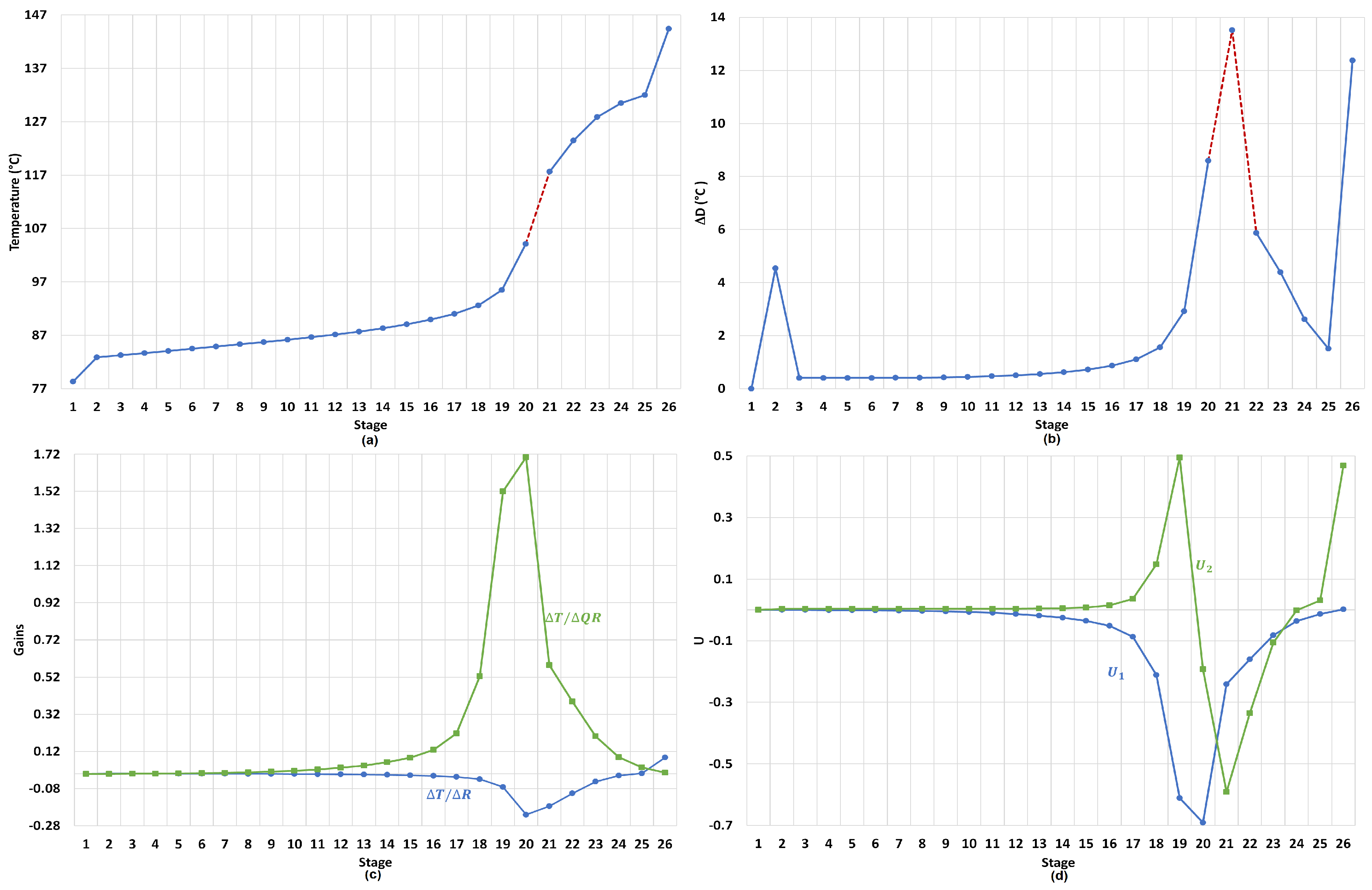
3.1.1. Stages for Sensor Locations in Dual-Temperature Control
3.1.2. Reflus/Boilup Structure for Dual Temperature Control
- TC1 loop: The reflux is used to regulate the temperature in tray 20.
- TC2 loop: The reboiler heat duty is used to regulate the temperature in tray 22.
- PC loop: The condenser pressure is controlled by manipulating the condenser duty.
- LC1 loop: The reflux-drum level is regulated by manipulating the distillate flow.
- LC2 loop: The base level is regulated by manipulating the bottoms flow.
- FEED-2 loop: The fresh salt feed to the column is an ideal flow control of the dissolved salt with the operational objective of keeping the concentration of the salt in the column stages as close as possible to 16.7 wt % (to preserve VLE estimation validity). The salt feed flow is calculated online in terms of the feed, distillate flows and the reflux.
3.2. Control of a Single Tray Temperature
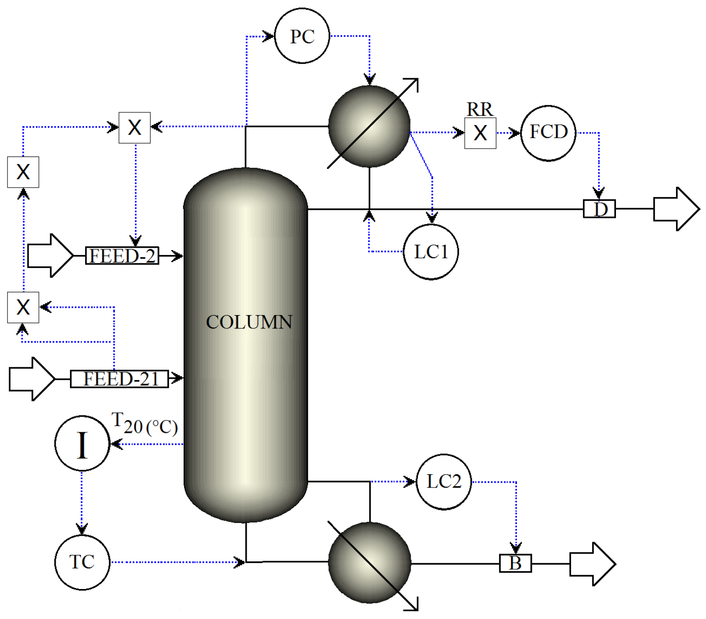
3.2.1. Reflux Ratio Structure for Single Temperature Control
- FCD loop: The distillate flow rate is rationed to the reflux flow rate.
- LC1 loop: The reflux-drum level is regulated by manipulating the reflux.
- LC2 loop: The base level is regulated by manipulating the bottoms flow.
- PC loop: The condenser pressure is controlled by manipulating the condenser duty.
- TC loop: The reboiler heat is used to regulate the temperature in tray 20.
- FEED-2 loop: The fresh salt feed to the column is an ideal flow control of the dissolved salt with the operational objective of keeping the concentration of the salt in the column stages as close as possible to 16.7 wt % (to preserve VLE estimation validity). The salt feed flow is calculated online in terms of the feed, distillate flows and the reflux.
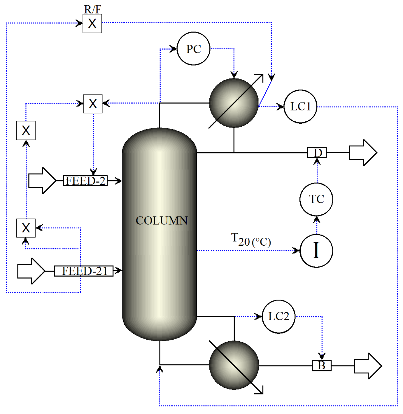
3.2.2. Reflux to Feed Ratio Structure for Single Temperature Control
- R/F loop: The flow rate of the reflux is rationed to the feed flow rate.
- LC1 loop: The reflux-drum level is regulated by manipulating the reboiler heat.
- LC2 loop: The base level is regulated by manipulating the bottoms flow.
- PC loop: The condenser pressure is controlled by manipulating the condenser duty.
- TC loop: The distillate flow is used to regulate the temperature in tray 20.
- FEED-2 loop: The fresh salt feed to the column is an ideal flow control of the dissolved salt with the operational objective of keeping the concentration of the salt in the column stages as close as possible to 16.7 wt % (to preserve VLE estimation validity). The salt feed flow is calculated online in terms of the feed, distillate flows and the reflux.
4. Evaluation of Control Structures: Results and Discussion
4.1. Performance of the Dual and Single-End Mode Temperature Control Structures
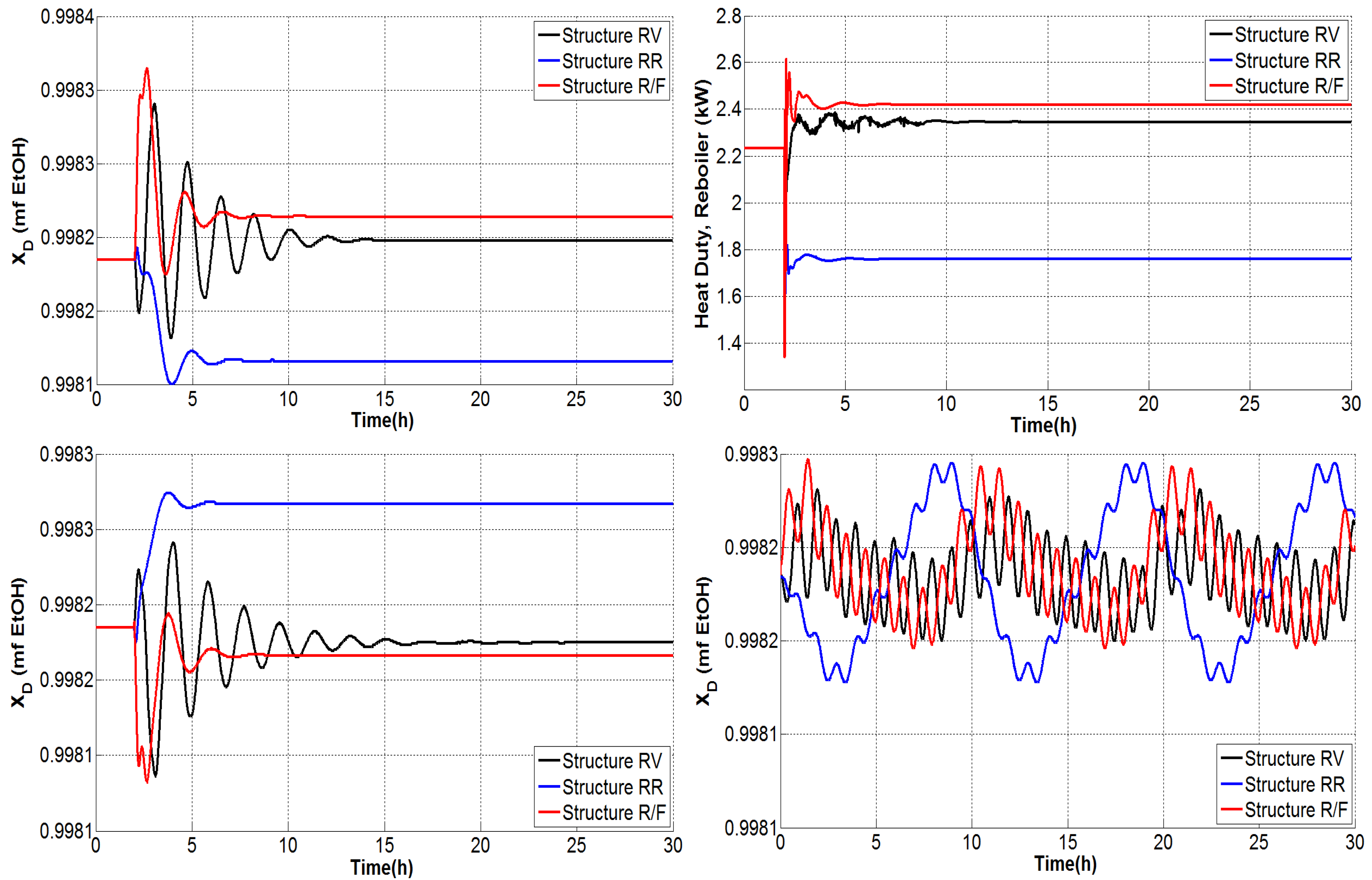
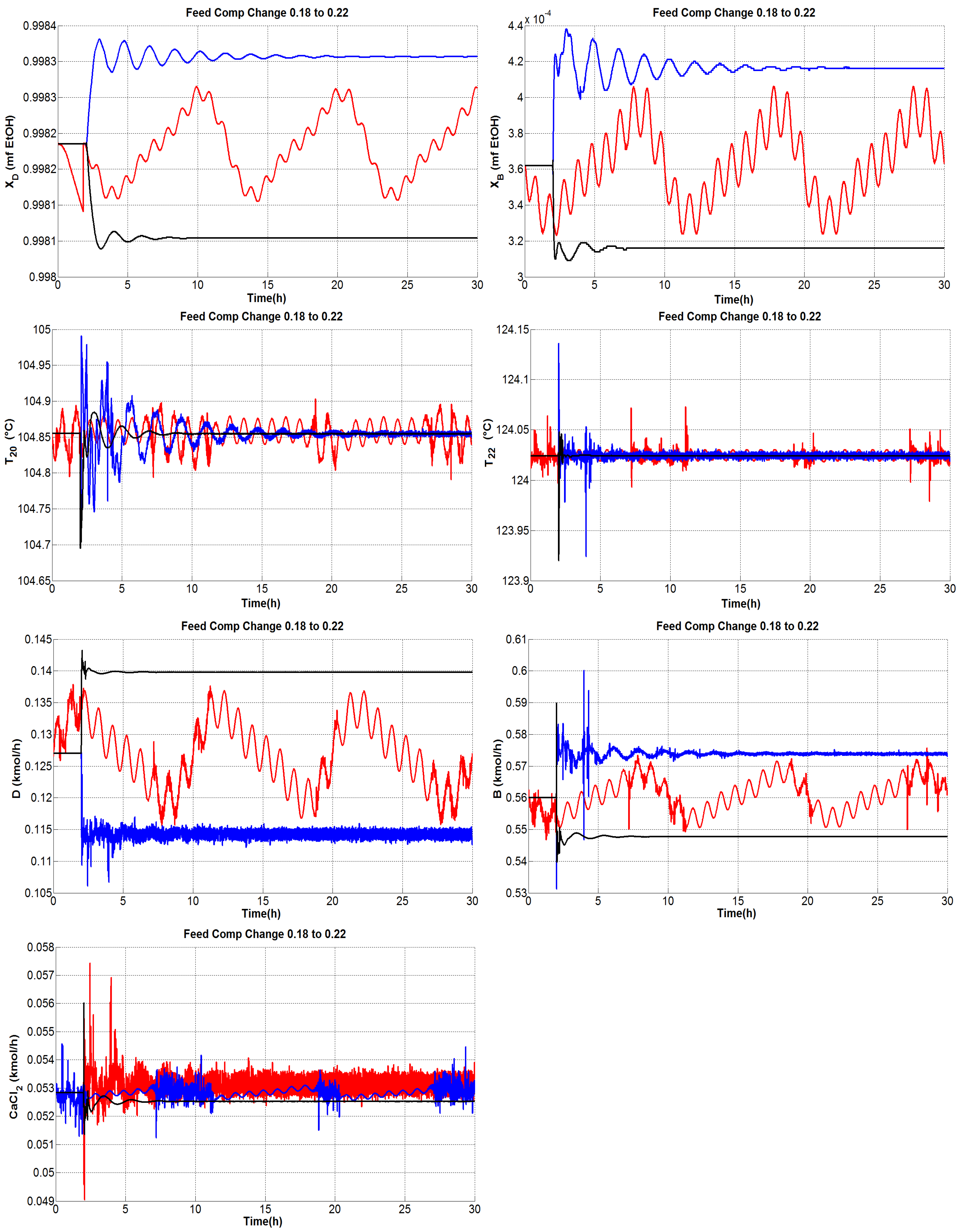
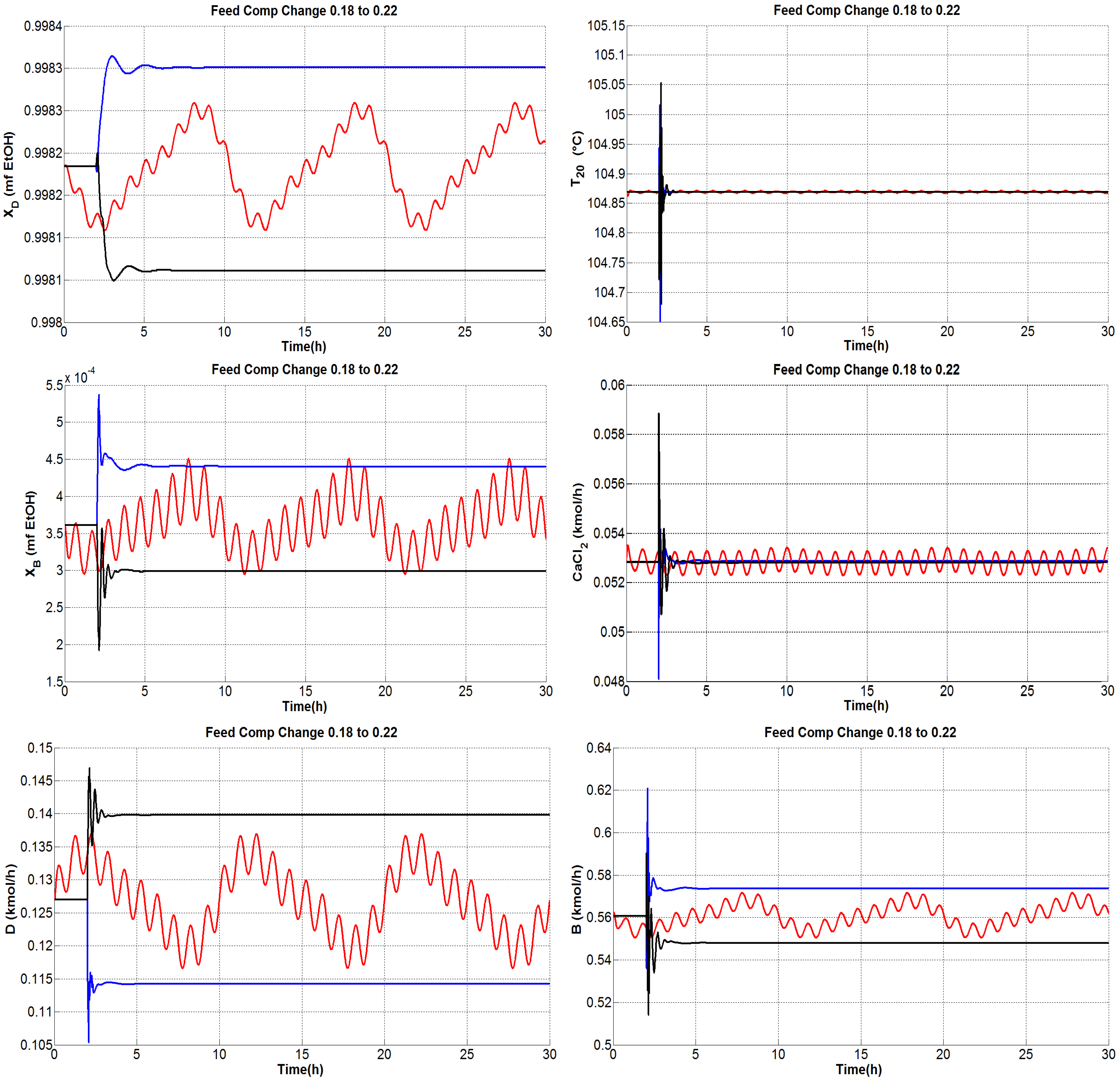
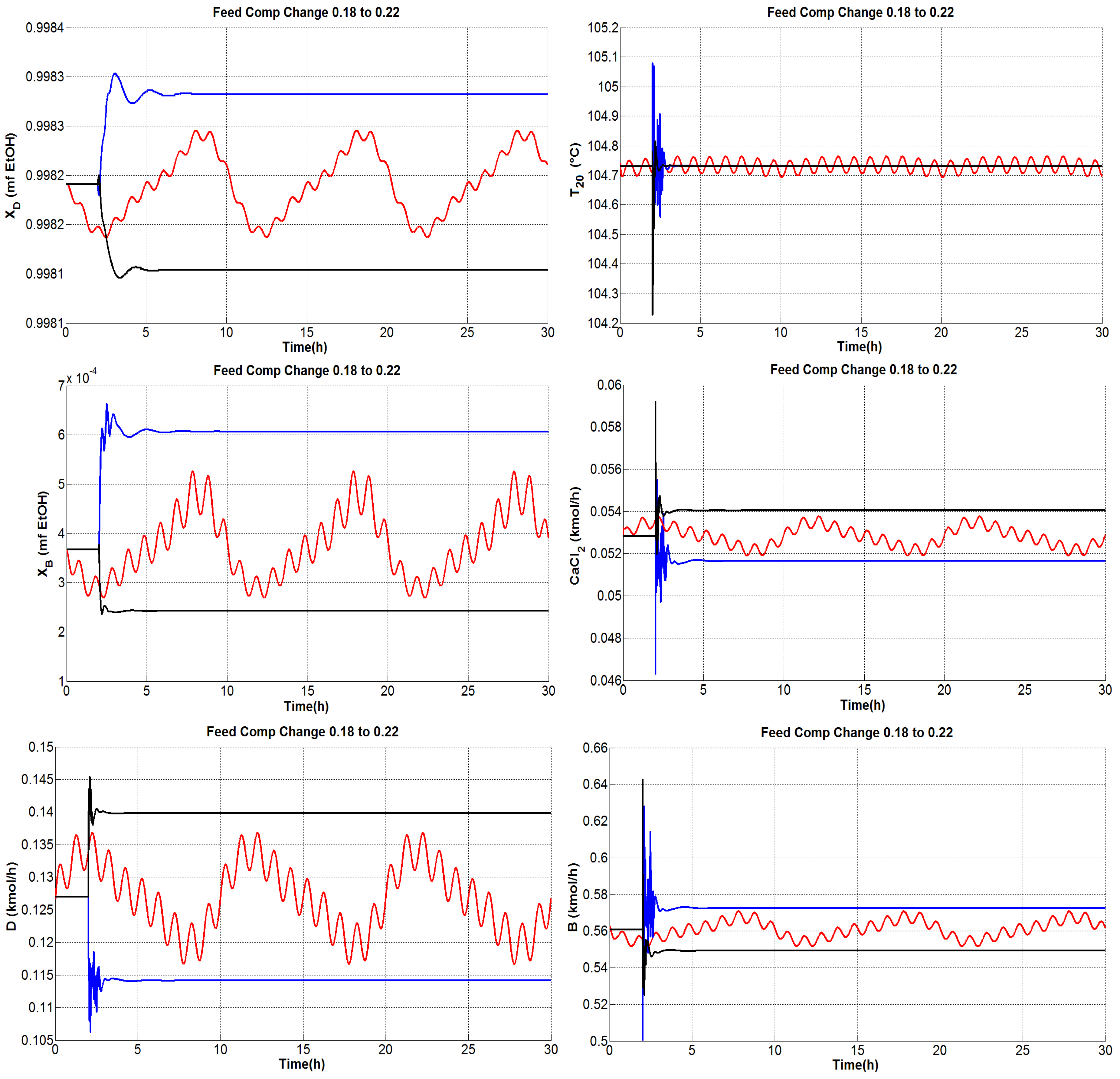
4.1.1. Tests under Perturbations on the Feed Composition
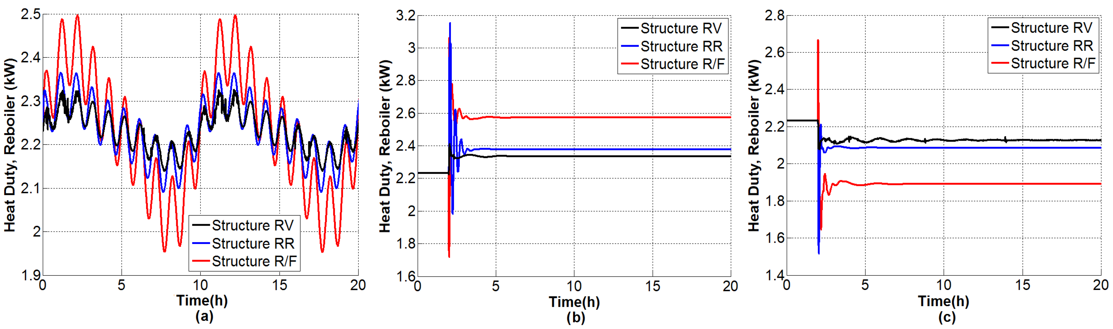
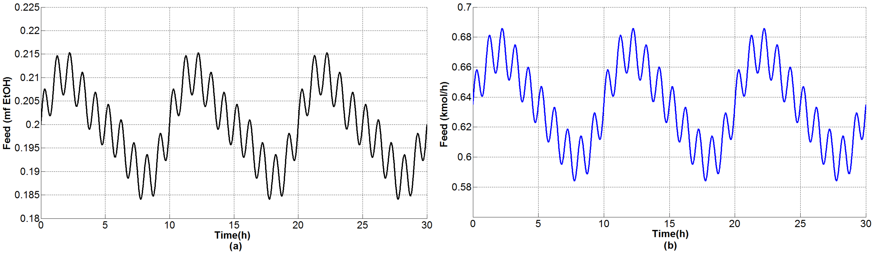
4.1.2. Tests under Perturbations on the Feed Flow Rate
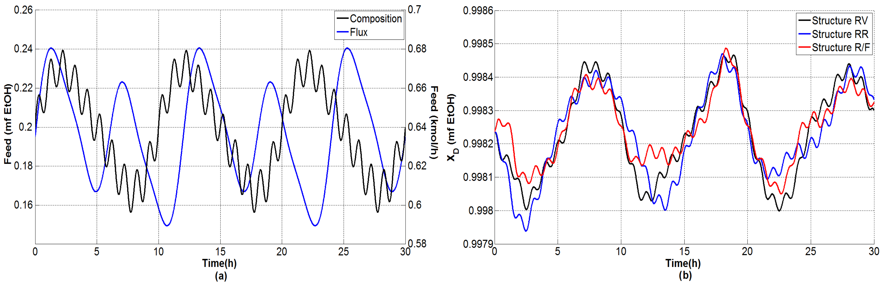
4.1.3. Tests under Multiple Perturbations
4.1.4. General Outcomes
- The composition of the bottom product was regulated effectively and the molar fraction was kept consistently on the order of .
- The dual temperature control was to some extent oscillating, but it was markedly improved with the single-end control mode.
- The flow rate of CaCl feed needs indeed undergo fast changes as the inner and external flows change. Because only steady-state studies are reported, it should be useful to verify, in practice, the effect of modifying the salt flow rate with rapid changes, keeping in mind that there exist dissolution difficulties.
- The distillate and bottoms flow rates remain close to the nominal value during the proposed tests; hence, the production rate of absolute ethanol is not affected adversely by disturbances.
- The secondary control loops are correctly achieved and maintain in general a stable operation.
5. Conclusions
Acknowledgments
Author Contributions
Conflicts of Interest
References
- Zabed, H.; Sahu, J.; Boyce, A.; Faruq, G. Fuel ethanol production from lignocellulosic biomass: An overview on feedstocks and technological approaches. Renew. Sustain. Energy Rev. 2016, 66, 751–774. [Google Scholar] [CrossRef]
- Chuck-Hernández, C.; Pérez-Carrillo, E.; Heredia-Olea, E.; Serna-Saldívar, S. Sorgo como un cultivo multifacético para la producción de bioetanol en México: Tecnologías, avances y áreas de oportunidad. Revista Mexicana de Ingeniería Química 2011, 10, 529–549. [Google Scholar]
- Naik, S.; Goud, V.V.; Rout, P.K.; Dalai, A.K. Production of first and second generation biofuels: A comprehensive review. Renew. Sustain. Energy Rev. 2010, 14, 578–597. [Google Scholar] [CrossRef]
- Madson, P.; Monceaux, D. Fuel ethanol production. In The Alcohol Textbook; Lyons, T., Kelsall, D., Murtagh, J., Eds.; Nottingham University Press: Nottingham, UK, 1995; pp. 257–268. [Google Scholar]
- Hettinga, W.; Junginger, H.; Dekker, S.; Hoogwijk, M.; McAloon, A.; Hicks, K. Understanding the reductions in US corn ethanol production costs: An experience curve approach. Energy Policy 2009, 37, 190–203. [Google Scholar] [CrossRef]
- Tolsma, J.E. Simulation and Analysis of Heteroazeotropic Systems. Ph.D. Thesis, Massachusetts Institute of Technology, Cambridge, MA, USA, 1999. [Google Scholar]
- Cardona, C.A.; Sanchez, O.J. Fuel ethanol production: Process design trends and integration opportunities. Bioresour. Technol. 2007, 98, 2415–2457. [Google Scholar] [CrossRef]
- Kumar, S.; Singh, N.; Prasad, R. Anhydrous ethanol: A renewable source of energy. Renew. Sustain. Energy Rev. 2010, 14, 1830–1844. [Google Scholar] [CrossRef]
- Quintero, J.; Montoya, M.; Sanchez, O.; Cardona, C. Evaluation of fuel ethanol dehydration through process simulation. Biotecnología en el Sector Agropecuario y Agroindustrial 2007, 5, 72–83. [Google Scholar]
- Zhu, Z.; Ri, Y.; Li, M.; Jia, H.; Wang, Y.; Wang, Y. Extractive distillation for ethanol dehydration using imidazolium-based ionic liquids as solvents. Chem. Eng. Process. 2016, 109, 190–198. [Google Scholar] [CrossRef]
- Tsanas, C.; Tzani, A.; Papadopoulos, A.; Detsi, A.; Voutsas, E. Ionic liquids as entrainers for the separation of the ethanol/water system. Fluid Phase Equilibria 2014, 379, 148–156. [Google Scholar] [CrossRef]
- Figueroa, J.; Lunelli, B.H.; Filho, R.M.; Maciel, M.W. Improvements on Anhydrous Ethanol Production by Extractive Distillation using Ionic Liquid as Solvent. Procedia Eng. 2012, 42, 1016–1026. [Google Scholar] [CrossRef]
- Pereiro, A.; Araújo, J.; Esperança, J.; Marrucho, I.; Rebelo, L. Ionic liquids in separations of azeotropic systems—A review. J. Chem. Thermodyn. 2012, 46, 2–28. [Google Scholar] [CrossRef]
- Ge, Y.; Zhang, L.; Yuan, X.; Geng, W.; Ji, J. Selection of ionic liquids as entrainers for separation of (water + ethanol). J. Chem. Thermodyn. 2008, 40, 1248–1252. [Google Scholar] [CrossRef]
- Quijada-Maldonado, E.; Aelmans, T.; Meindersma, G.; de Haan, A. Pilot plant validation of a rate-based extractive distillation model for water-ethanol separation with the ionic liquid [emim][DCA] as solvent. Chem. Eng. J. 2013, 223, 287–297. [Google Scholar] [CrossRef]
- Ramírez-Corona, N.; Ek, N.; Jiménez-Gutiérrez, A. A method for the design of distillation systems aided by ionic liquids. Chem. Eng. Process. 2015, 87, 1–8. [Google Scholar] [CrossRef]
- Soares, R.; Pessoa, F.; Mendes, M. Dehydration of ethanol with different salts in a packed distillation column. Process Saf. Environ. Prot. 2015, 93, 147–153. [Google Scholar] [CrossRef]
- Grundl, G.; Müller, M.; Touraud, D.; Kunz, W. Salting-out and salting-in effects of organic compounds and applications of the salting-out effect of Pentasodium phytate in different extraction processes. J. Mol. Liquids 2017, 236, 368–375. [Google Scholar] [CrossRef]
- Barba, D.; Brandani, V.; di Giacomo, G. Hyperazeotropic ethanol salted-out by extractive distillation. Theoretical evaluation and experimental check. Chem. Eng. Sci. 1985, 40, 2287–2292. [Google Scholar] [CrossRef]
- Pinto, R.; Wolf-Maciel, M.; Lintomen, L. Saline extractive distillation process for ethanol purification. Comput. Chem. Eng. 2000, 24, 1689–1694. [Google Scholar] [CrossRef]
- Ligero, E.; Ravagnani, T. Dehydration of ethanol with salt extractive distillation—A comparative analysis between processes with salt recovery. Chem. Eng. Process. 2003, 42, 543–552. [Google Scholar] [CrossRef]
- Huang, H.J.; Ramaswamy, S.; Tschirner, U.; Ramarao, B. A review of separation technologies in current and future biorefineries. Sep. Purif. Technol. 2008, 62, 1–21. [Google Scholar] [CrossRef]
- Nishi, Y. Vapor-liquid equilibrium relations for the system accompanied by hypothetical chemical reaction containing salt. J. Chem. Eng. Jpn. 1975, 8, 187–191. [Google Scholar] [CrossRef]
- Zhou, R.; Duan, Z. Extractive distillation with salt in solvent. Tsinghua Sci. Technol. 1999, 4, 1477–1479. [Google Scholar]
- Vasquez, C.; Ruiz, C.; Arango, D.; Caicedo, R.; Sanchez, M.; Rios, L.; Restrepo, G. Production of anhydrous ethanol by extractive distillation with salt effect. DYNA 2007, 74, 53–59. [Google Scholar]
- Llano-Restrepo, M.; Aguilar-Arias, J. Modeling and simulation of saline extractive distillation columns for the production of absolute ethanol. Comput. Chem. Eng. 2003, 27, 527–549. [Google Scholar] [CrossRef]
- Hashemi, N.; Pazuki, G.; Vossoughi, M.; Hemmati, S.; Saboohi, Y. Application of a New Gibbs Energy Equation to Model a Distillation Tower for Production of Pure Ethanol. Chem. Eng. Technol. 2011, 34, 1715–1722. [Google Scholar] [CrossRef]
- Luyben, W.L. Effect of Feed Composition on the Selection of Control Structures for High-Purity Binary Distillation. Ind. Eng. Chem. Res. 2005, 44, 7800–7813. [Google Scholar] [CrossRef]
- Luyben, W.L. Evaluation of criteria for selecting temperature control trays in distillation columns. J. Process Control 2006, 16, 115–134. [Google Scholar] [CrossRef]
- Luyben, W.L. Distillation Design and Control Using Aspen Simulation; John Wiley Sons: Hoboken, NJ, USA, 2013. [Google Scholar]
- Skogestad, S.; Morari, M. Control configuration selection for distillation columns. AIChE J. 1987, 33, 1620–1635. [Google Scholar] [CrossRef]
- Skogestad, S.; Morari, M. Understanding the dynamic behavior of distillation columns. Ind. Eng. Chem. Res. 1988, 27, 1848–1862. [Google Scholar] [CrossRef]
- Skogestad, S.; Morari, M. LV-Control of a high-purity distillation column. Chem. Eng. Sci. 1988, 43, 33–48. [Google Scholar] [CrossRef]
- Skogestad, S.; Lundström, P.; Jacobsen, E.W. Selecting the best distillation control configuration. AIChE J. 1990, 36, 753–764. [Google Scholar] [CrossRef]
- Skogestad, S. Dynamics and Control of Distillation Columns. Chem. Eng. Res. Des. 1997, 75, 539–562. [Google Scholar] [CrossRef]
- Skogestad, S. Plantwide control: The search for the self-optimizing control structure. J. Process Control 2000, 10, 487–507. [Google Scholar] [CrossRef]
- Skogestad, S. Self-optimizing control: The missing link between steady-state optimization and control. Comput. Chem. Eng. 2000, 24, 569–575. [Google Scholar] [CrossRef]
- Skogestad, S. The Dos and Don’ts of Distillation Column Control. Chem. Eng. Res. Des. 2007, 85, 13–23. [Google Scholar] [CrossRef]
- Waller, K.V.; Finnerman, D.H.; Sandelin, P.M.; Haeggblom, K.E.; Gustafsson, S.E. An experimental comparison of four control structures for two-point control of distillation. Ind. Eng. Chem. Res. 1988, 27, 624–630. [Google Scholar] [CrossRef]
- Wolff, E.A.; Skogestad, S. Control configuration selection for distillation columns under temperature control. In Proceedings of the 2nd European Control Conference, Groningen, The Netherlands, 28 June–1 July 1993; pp. 637–642. [Google Scholar]
- Wolff, E.A.; Skogestad, S. Temperature Cascade Control of Distillation Columns. Ind. Eng. Chem. Res. 1996, 35, 475–484. [Google Scholar] [CrossRef]
- Khelassi, A.; Bendib, R.; Benhalla, A. Configurations of binary distillation column for optimal control. Proceedings of 2012 UKACC International Conference on Control, Cardiff, UK, 3–5 September 2012; pp. 793–797. [Google Scholar]
- Luyben, W.L. Control of a multiunit heterogeneous azeotropic distillation process. AIChE J. 2006, 52, 623–637. [Google Scholar] [CrossRef]
- Ramos, W.B.; Figueiredo, M.F.; Brito, R.P. Optimization of Extractive Distillation Process with a Single Column for Anhydrous Ethanol Production. Comput. Aided Chem. Eng. 2014, 33, 1411–1416. [Google Scholar]
- Figueiredo, M.F.D.; Brito, K.D.; Ramos, W.B.; Vasconcelos, L.G.S.; Brito, R.P. Effect of Solvent Content on the Separation and the Energy Consumption of Extractive Distillation Columns. Chem. Eng. Commun. 2015, 202, 1191–1199. [Google Scholar] [CrossRef]
- Ramos, W.; Figueirêdo, M.; Brito, K.; Brito, R. Effect of Solvent Content on Controllability of Extractive Distillation Columns. Comput. Aided Chem. Eng. 2015, 37, 1607–1612. [Google Scholar]
- Ramos, W.B.; Figueirêdo, M.F.; Brito, K.D.; Ciannella, S.; Vasconcelos, L.G.S.; Brito, R.P. Effect of Solvent Content and Heat Integration on the Controllability of Extractive Distillation Process for Anhydrous Ethanol Production. Ind. Eng. Chem. Res. 2016, 55, 11315–11328. [Google Scholar] [CrossRef]
- Ramos, W.; Figueirêdo, M.; Brito, K.; Brito, R. Control of an Extractive Distillation Column with Thermal Integration. Comput. Aided Chem. Eng. 2016, 38, 1329–1334. [Google Scholar]
- Luyben, W.L. Comparison of extractive distillation and pressure-swing distillation for acetone/chloroform separation. Comput. Chem. Eng. 2013, 50, 1–7. [Google Scholar] [CrossRef]
- Sander, B.; Fredenslund, A.; Rasmussen, P. Calculation of vapour-liquid equilibria in mixed solvent/salt systems using an extended UNIQUAC equation. Chem. Eng. Sci. 1986, 41, 1171–1183. [Google Scholar] [CrossRef]
- Pasa, V.M.D. Recomendaciones de Especificaciones Técnicas Para el Etanol y sus Mezclas (E6) y la Infraestructura para su Manejo en México. SENER/ GTZ: Mexico City, Mexico, 2010; p. 100. [Google Scholar]
- Luyben, W. Plantwide Dynamic Simulators in Chemical Processing and Control; CRC Press: Boca Raton, FL, USA, 2002. [Google Scholar]
- Luyben, W.L. Practical Distillation Control; Springer Science & Business Media: Berlin, Germany, 2012. [Google Scholar]
- Skogestad, S.; Morari, M. Implications of large RGA-elements on control performance. Ind. Eng. Chem. Res. 1987, 26, 2323–2330. [Google Scholar] [CrossRef]
- Luyben, W.L. Use of Mass or Molar Reflux-to-Feed Ratios In Distillation Single-End Control Structures. Ind. Eng. Chem. Res. 2013, 52, 15883–15895. [Google Scholar] [CrossRef]


| Ethanol–Water (NRTL) | Ethanol–Water-CaCl (ENRTL) | ||||
|---|---|---|---|---|---|
| Binary Interactions | Molecule–Molecule Pairs | Molecule–Electrolyte Pairs | |||
| i j | Ethanol Water | m m | Ethanol Water | m | Ethanol |
| m | Water | ||||
| ca | CaCl | ||||
| a | −0.8009 | −0.141166 | 50.7409314 | ||
| a | 3.4578 | 1.8872 | −25.439654 | ||
| b | 246.18 | 0.3 | 0.0293 | ||
| b | −586.0809 | 11.6224635 | |||
| c | 0.3 | −5.8749949 | |||
| 0.2 | |||||
| 0 | 0 | 0 | 0 | 102.80 | 104.51 | 1.71 |
| 0.02 | 0.271 | 0.271 | 96.00 | 97.74 | 1.74 | |
| 0.04 | 0.389 | 0.389 | 91.60 | 91.33 | 0.27 | |
| 0.10 | 0.542 | 0.542 | 85.00 | 84.29 | 0.71 | |
| 0.20 | 0.647 | 0.647 | 82.45 | 82.33 | 0.12 | |
| 0.30 | 0.694 | 0.694 | 81.45 | 81.80 | 0.35 | |
| 0.40 | 0.753 | 0.753 | 81.25 | 82.40 | 1.15 | |
| 0.50 | 0.795 | 0.795 | 80.70 | 82.38 | 1.68 | |
| 0.60 | 0.828 | 0.828 | 81.50 | 82.03 | 0.53 | |
| 0.70 | 0.867 | 0.867 | 81.50 | 81.79 | 0.29 | |
| 0.80 | 0.915 | 0.915 | 82.40 | 81.74 | 0.66 | |
| 0.90 | 0.942 | 0.942 | 81.65 | 81.05 | 0.60 |
| Input/Output Data and Specified Parameters | Symbol | Value |
|---|---|---|
| Input data and specified parameters | ||
| Number of equilibrium stages | N | 26 |
| Main feed stage | 21 | |
| Column efficiency (%) | 50 | |
| Main feed thermodynamic state | Saturated vapor | |
| Main feed temperature () | T | 94.5 |
| Main feed molar flow rate (/) | F | 0.635 |
| Main feed ethanol mole fraction | z | 0.2 |
| Main feed water mole fraction | z | 0.8 |
| Salt feed molar flow rate (/) | F | 0.528 |
| Salt feed temperature () | T | 78.3 |
| Distillate molar flow rate (/) | D | 0.127 |
| Reflux Ratio | 6.42 | |
| Operating pressure (bar) | P | 1.01325 |
| Output data | ||
| Ethanol molar flow rate in distillate (/) | D | 0.127 |
| Water molar flow rate in distillate (/) | D | 0.0017 |
| Condenser heat duty (kW) | Q | −10.205 |
| Reboiler heat duty (kW) | Q | 2.2319 |
| Controller | PC | LC1 | LC2 | TC1 | TC2 | |
|---|---|---|---|---|---|---|
| P | 13.9 | 74.4 | 1616 | 1.9 | 58.9 | |
| I | 2.4 | 1.2 | 0.6 | 6.9 | 2.7 | |
| D | 0.6 | 0.3 | 0.15 | 1.73 | 0.68 | |
| Controller | PC | LC1 | LC2 | TC1 | FCD | |
|---|---|---|---|---|---|---|
| P | 32.9 | 640 | 141 | 121.1 | 0.63 | |
| I | 2.5 | 1 | 1 | 1.5 | 2 | |
| Controller | PC | LC1 | LC2 | TC1 | |
|---|---|---|---|---|---|
| P | 20 | 408 | 269.4 | 4.6 | |
| I | 1.2 | 0.9 | 43.2 | 4.5 | |
| D | 0.3 | 0.225 | 10.8 | 1.125 | |
| Structure | Perturbation | Bias () | ISE () | IAE | ITAE | ITAE | Average Heat Duty (kW) |
|---|---|---|---|---|---|---|---|
| Step (+10) | 0.131 | 47.40 | 0.363 | 5.863 | 0.045 | 2.328 | |
| Step (−10) | −0.122 | 41.20 | 0.338 | 5.448 | 0.108 | 2.134 | |
| RV | Sinusoidal | 6.430 | 0.120 | 1.820 | 2.231 | ||
| Step (+10) | 0.124 | 42.35 | 0.343 | 5.546 | 0.040 | 2.369 | |
| Step (−10) | −0.116 | 37.16 | 0.321 | 5.190 | 0.038 | 2.095 | |
| RR | Sinusoidal | 5.854 | 0.114 | 1.735 | 2.231 | ||
| Step (+10) | 0.081 | 18.04 | 0.224 | 3.623 | 0.028 | 2.550 | |
| Step (−10) | −0.097 | 26.16 | 0.269 | 4.343 | 0.036 | 1.913 | |
| R/F | Sinusoidal | 3.281 | 0.085 | 1.334 | 2.230 |
| Structure | Perturbation | M () | t (h) | t (h) | t (h) |
|---|---|---|---|---|---|
| RV | Step (+10) | −15 | 1.05 | 0.73 | 7.20 |
| Step (−10) | 21 | 1.05 | 0.60 | 18.53 | |
| RR | Step (+10) | −12 | 1.10 | 0.79 | 4.68 |
| Step (−10) | 13 | 1.01 | 0.67 | 6.73 | |
| R/F | Step (+10) | −0.8 | 1.37 | 0.98 | 3.76 |
| Step (−10) | 21 | 1.06 | 0.63 | 5.85 |
| Structure | Perturbation | Bias () | ISE () | IAE | ITAE | ITAE | Average Heat Duty (kW) |
|---|---|---|---|---|---|---|---|
| RV | Step (+10) | −0.013 | 1.436 | 0.048 | 0.632 | 0.109 | 2.335 |
| Step (−10) | 0.010 | 1.227 | 0.042 | 0.517 | 0.136 | 2.135 | |
| Sinusoidal | 1.163 | 0.049 | 0.739 | 2.235 | |||
| RR | Step (+10) | 0.069 | 12.83 | 0.187 | 3.075 | 0.041 | 1.789 |
| Step (−10) | −0.082 | 18.28 | 0.224 | 3.663 | 0.033 | 2.669 | |
| Sinusoidal | 4.175 | 0.098 | 1.650 | 2.310 | |||
| R/F | Step (+10) | −0.029 | 3.396 | 0.088 | 1.318 | 0.044 | 2.407 |
| Step (−10) | 0.019 | 16.78 | 0.059 | 0.865 | 0.036 | 2.059 | |
| Sinusoidal | 1.854 | 0.061 | 0.882 | 2.232 |
| Structure | ISE () | IAE | ITAE | Average Heat Duty (kW) |
|---|---|---|---|---|
| RV | 5.721 | 0.368 | 5.622 | 2.233 |
| RR | 5.560 | 0.353 | 4.957 | 2.208 |
| R/F | 3.326 | 0.268 | 4.165 | 2.226 |
© 2017 by the authors. Licensee MDPI, Basel, Switzerland. This article is an open access article distributed under the terms and conditions of the Creative Commons Attribution (CC BY) license (http://creativecommons.org/licenses/by/4.0/).
Share and Cite
Cantero, C.A.T.; Lopez, G.L.; Alvarado, V.M.; Jimenez, R.F.E.; Morales, J.Y.R.; Coronado, E.M.S. Control Structures Evaluation for a Salt Extractive Distillation Pilot Plant: Application to Bio-Ethanol Dehydration. Energies 2017, 10, 1276. https://doi.org/10.3390/en10091276
Cantero CAT, Lopez GL, Alvarado VM, Jimenez RFE, Morales JYR, Coronado EMS. Control Structures Evaluation for a Salt Extractive Distillation Pilot Plant: Application to Bio-Ethanol Dehydration. Energies. 2017; 10(9):1276. https://doi.org/10.3390/en10091276
Chicago/Turabian StyleCantero, Carlos Alberto Torres, Guadalupe Lopez Lopez, Victor M. Alvarado, Ricardo F. Escobar Jimenez, Jesse Y. Rumbo Morales, and Eduardo M. Sanchez Coronado. 2017. "Control Structures Evaluation for a Salt Extractive Distillation Pilot Plant: Application to Bio-Ethanol Dehydration" Energies 10, no. 9: 1276. https://doi.org/10.3390/en10091276
APA StyleCantero, C. A. T., Lopez, G. L., Alvarado, V. M., Jimenez, R. F. E., Morales, J. Y. R., & Coronado, E. M. S. (2017). Control Structures Evaluation for a Salt Extractive Distillation Pilot Plant: Application to Bio-Ethanol Dehydration. Energies, 10(9), 1276. https://doi.org/10.3390/en10091276