Article

A Comparison between Voltage and Reactive Power Feedback Schemes of DFIGs for Inter-Area Oscillation Damping Control

1
School of Electrical Engineering, Southwest Jiaotong University, Chengdu 610031, China
2
College of Electrical and Information Engineering, Southwest Minzu University, Chengdu 610041, China
*
Author to whom correspondence should be addressed.
Energies 2017, 10(8), 1206; https://doi.org/10.3390/en10081206
Submission received: 4 June 2017 / Revised: 21 July 2017 / Accepted: 3 August 2017 / Published: 14 August 2017

Abstract

:
Reactive power modulation of wind power plants is an effective way to damp inter-area oscillation in wind power penetrated power systems. For doubly fed induction generator (DFIG) based wind farms, there are two different ways to achieve reactive power modulation: one is via reactive power feedback control, and the other method is via voltage feedback control. While both of the control schemes are feasible, their effectiveness may differ, and there has not been a systematic comparison between them. This paper investigates the differences between these two feedback schemes for inter-area oscillation damping control. The principles of utilizing DFIG for damping control is introduced at first. Then, analytical techniques including the frequency domain analysis, μ -analysis and time domain analysis are used to systematically study the performance of the two control schemes against inter-area oscillation. The robustness of the control schemes with respect to the variety of system operation points is also studied. The results from this paper can provide an insight into the understatement of DFIG reactive modulation against oscillation and guidance for controller design.

1. Introduction

In the past few years, wind power penetration has significantly increased. Among the various wind power generators, a doubly fed induction generator (DFIG) is the most widely used one in wind energy conversion systems [1]. As the penetration level of DFIGs increases, their impact on system stability has been recognized [2,3].
DFIG employs feedback converter that consists of a grid-side converter (GSC) and a rotor-side converter (RSC) to feed the adjustable field current into rotor winding. The control capability of GSC and RSC gives DFIG additional advantages in flexible control over the conventional induction generators as concluded in [4]. Various interaction control, such as, power factor control and frequency control, may provide different damping contribution [5]. Many control strategies adopted to grid-connected DFIG have been studied to improve the power system stability, especially, for the enhancement of system damping [6,7,8]. The damping controllers are multiform based on active power regulation, reactive power regulation or coordinated regulation method with active and reactive power regulation [5]. To damp power system oscillations, the power system stabilizer (PSS) installed on RSC was designed for DFIG in [6]. Since a large number of parameters are required in the control system of RSC and GSC, the robust control theory and intelligent algorithms have been applied to design damping controller and to tune parameters for DFIG for further improving the system dynamic performance [9].
Utilizing reactive power control to damp oscillations has been identified as an effective way and was originally applied in a static synchronous compensator and static Var compensator [10]. For DFIG, the flexible control of a rotor side converter gives the capability of modulating active/reactive power easily. However, the active power of DFIG and the electromagnetic torque is directly related. The frequency of both torsional oscillation and active power modulation oscillation are quite low. It means that the modulation on active power for low-frequency oscillations damping control may interact with torsional oscillations. In contrast, reactive power is not directly related to the electromagnetic torque and will not cause the interacting problem. The differences between via active power control loop and reactive power control loop of DFIG for damping control has been investigated in [11]. It has been widely shown that reactive control is advantageous not only because of little torsional oscillation, but also the slight changing on active power output, which is according to the maximum power point tracking (MPPT) reference value for DFIG.
There are two possible feedback control loops to achieve reactive power modulation of DFIG: one is reactive power feedback control, and the other is voltage feedback control. The DFIG connected bus voltage is associated with the active power and reactive power level of the whole system. The output reactive power of DFIG is only related to the control reference value. While both of the control schemes are feasible, their effectiveness varies and there has not been a systematic comparison between them.
The main objective of this paper is to systematically and numerically investigate the differences between DFIG voltage and reactive feedback control schemes for inter-area oscillation damping. A two-area four-machine system with a DFIG-based wind generation integrated is used as the platform to demonstrate the analytical results of frequency domain and time domain simulations. The robustness of the control scheme is also evaluated with the μ -analysis. The value of this paper is that it provides a deeper insight into the understanding of reactive modulation of DFIG for oscillation damping and guiding the controller design for practical use.
This paper is organized as follows: Section 1 gives the introduction; Section 2 describes the modeling of a test system including the control system of the rotor side converter; Section 3 shows the comparison results and gives the detailed discussion; and Section 4 provides the conclusions.

2. Model Development

In this paper, a model of a two-area four-machine system integrated with a DFIG based wind farm is developed for specific analysis. The damping effect from the voltage-based feedback control loop and reactive power-based feedback control loop in DFIG are analyzed in the frequency domain and the time domain. The model in this paper takes the dynamic features of DFIG into account, which play an important role in the system dynamic analysis. Specifically, the model of DFIG includes aerodynamic, turbine shaft dynamic, induction generator dynamic, DC link dynamic and the dynamic behaviors of the back-to-back converters and the corresponding control system of RSC and GSC [12,13]. The mathematical modeling of the DFIG dynamic behaviors is detailed in [14]. Based on the dynamic model of a two-area four-machine system with DFIG, a fix-phase oscillation damping controller is integrated into the DFIG model.

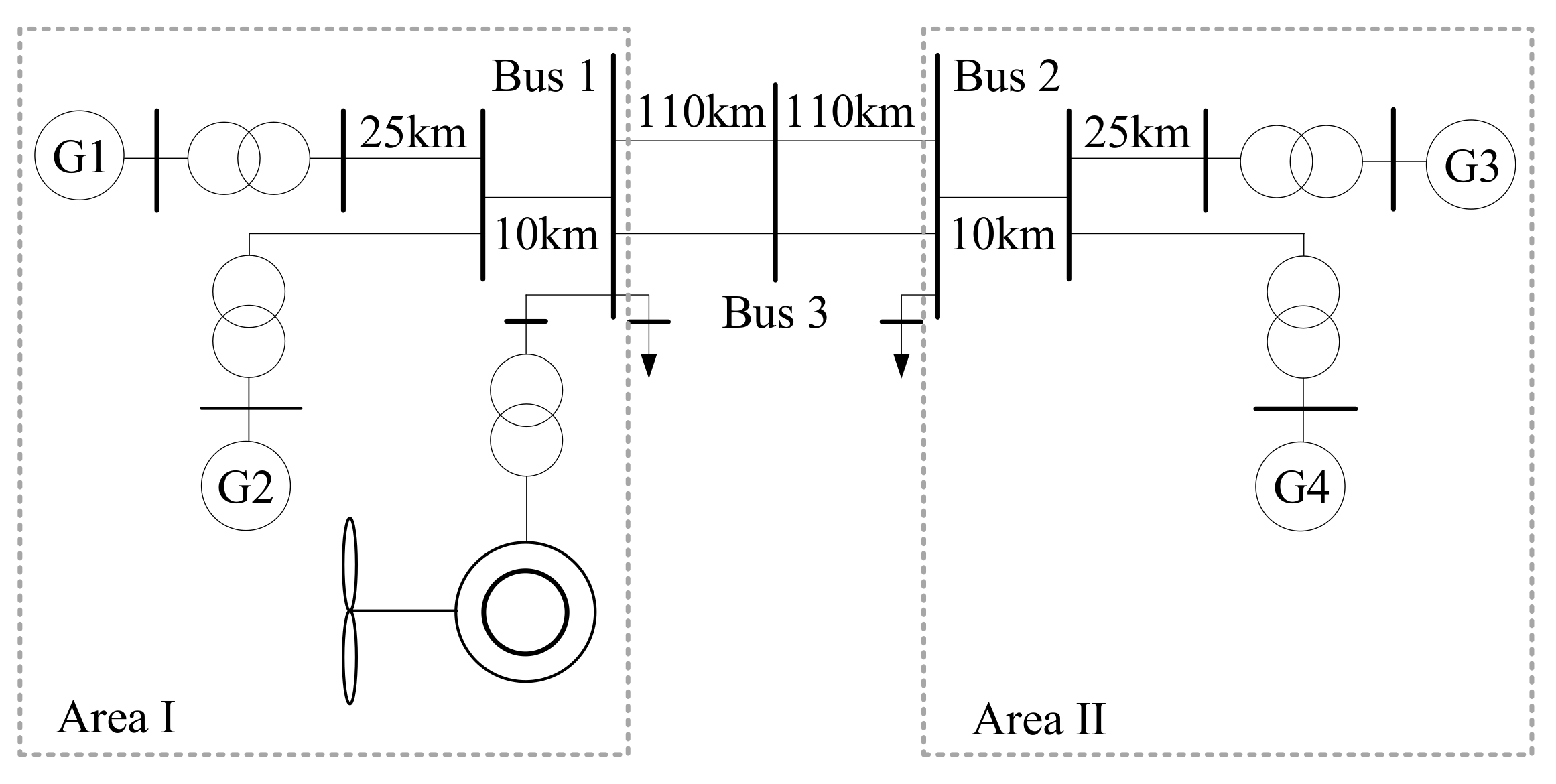
2.1. Two-Area Power System Model

The structure of the test system is shown in Figure 1 [15,16]. Both Area I and Area II have two synchronous generators installed. All four of the synchronous generators are identical with rated power of 900 MW and equipped with turbine governors. A PSS on generator 1 is considered in this study. The DFIG based wind farm is connected to bus 1 in area I. The wind farm is represented by one aggregated DFIG. The parameters of DFIG, synchronous generators and control blocks of turbine governor can be found in Appendix A. For the studied system, the penetration rate of wind power is considered to be 10% under rated output [15], and the size of wind farm is determined based on that. However, lower or higher penetration levels of wind power can also be considered without losing the generality of this study.
The inter-area oscillation mode, with a frequency of 3.74 rad/s in the study system, is employed to study the damping effect of reactive power feedback control and voltage feedback control. Accordingly, the damping controller is developed for the inter-area oscillation mode.

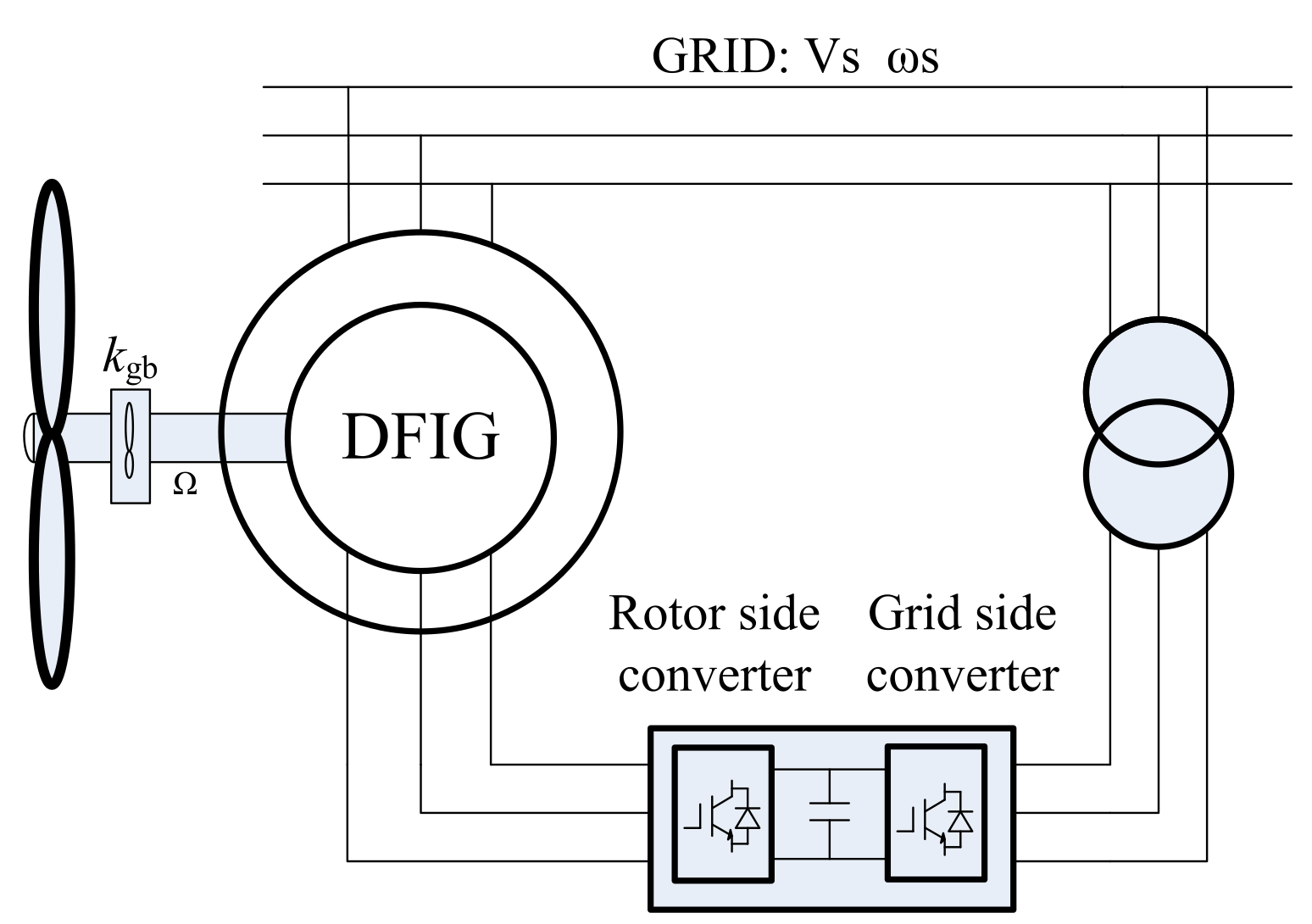
2.2. Model of Doubly Fed Induction Generator

In this paper, a grid-connected DFIG is considered. The proposed control scheme for DFIG will help damp the inter-area oscillation while its dynamics are considered in detecting the lead leg phase in a control scheme. In particular, the model of DFIG consists of aerodynamic, turbine shaft dynamic, DFIG machine dynamic, RSC, GSC and control systems of the converters. In particular, the dynamic model of the DFIG includes the DC link capacitor dynamic and converter transients that are modeled in detail in this paper, while they are usually not considered in other studies [5,11]. The topology of the DFIG-based wind energy conversion system is shown in Figure 2. The detailed models of its components are briefly given below.

2.2.1. Drive Train of Wind Turbine (WT)

In this paper, a two-mass model is assumed to represent the WT is applied. This model takes the torsional flexibility into consideration to study the WT mechanical dynamics. Since this paper aims to capture the torsional dynamic, the two mass model is sufficient to represent the interested dynamics, as given below:
2 H t d ω t d t = T m T s h ,
2 H g d ω r d t = T s h T e ,
d T s h d t = K t g ω e ( ω t ω r ) .

2.2.2. Generator

For the DFIG, the stator supplies power to the grid directly and the rotor supplies power to the grid via a back-to-back electric converters, which is the key unit to achieve the control objective of rotor speed, active and reactive power generation. The commonly used synchronously rotating dq reference frame is employed here to model the dynamic behavior of the DFIG. In this study, the voltage behind transient resistance and stator currents are selected as the state variables. Then, the differential equations of stator and rotor circuits of the induction generator in the dq reference frame can be obtained as follows:
d e d d t = X s X T i q s 1 T 0 e d + s ω s e q ω s L m L r r v q r ,
d e q d t = X s X T i d s 1 T 0 e q s ω s e d + ω s L m L r r v d r ,
d i d s d t = ω s X v d s ( ω s X R s + 1 X T 0 ( X s X ) ) i d s + ω s ( 1 s ) X e d L m ω s L r r X v d r + 1 X T 0 e q + ω s i q s ,
d i q s d t = ω s X v q s ( ω s X R s + 1 X T 0 ( X s X ) ) i q s + ω s ( 1 s ) X e q L m ω s L r r X v q r + 1 X T 0 e d + ω s i d s ,
where e q = ω s L m ( i d r + L m L r r i d s ) , e d = ω s L m ( i q r + L m L r r i q s ) , X = ω s L s s , X = ω s L r r ( L s s L r r L m 2 ) , T 0 = L r r R r .

2.2.3. Dynamics of DC Link

The dynamic of the DC link with a capacitor installed between the RSC and GSC can be represented by the dynamic of the DC voltage stabilization capacity, which is a first-order dynamic model as given in (8):
C v D C d v D C d t = P r P g .

2.2.4. Dynamics of Converters

The voltage source converter is used for the GSC and RSC of DFIG. The dynamic models of the converter in the dq reference frame are shown in Equations (9) and (10):
d i d r d t = 1 L u c d R L i d 1 L u s d ω i q r ,
d i q r d t = 1 L u c d R L i q 1 L u s q + ω i d r .
The dynamic model of RSC and GSC is similar. For RSC, the AC side means the rotor winding side. For GSC, the AC side means the grid side.

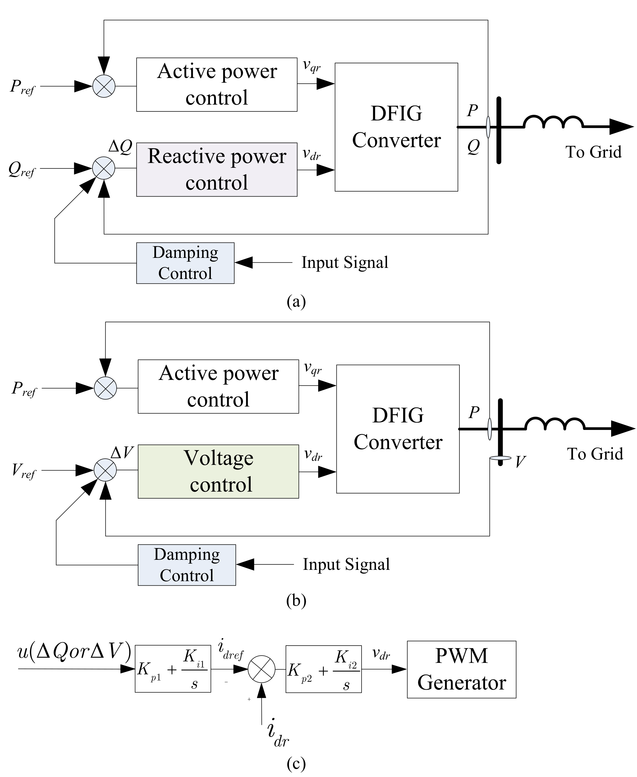
2.2.5. Controller of Doubly Fed Induction Generator Converters

(1) Controller for Rotor Side Converter (RSC)
There are two ways to modulate the reactive power of DFIG. The first one is with reactive power feedback, as shown in Figure 3a. The second one is with voltage feedback, as shown in Figure 3b. The control scheme of RSC, which is considered in this study, is shown in Figure 3c. Four PI controllers that are distributed in two control loops. In the q-axis voltage of RSC, u q r , is employed to control the active power, while the d-axis voltage, u d r , is used to control the reactive power. The d- and q-axis control loops are used to keep the output active and reactive powers of DFIG, according to the reference value, respectively. The dynamic model of the RSC control system is given below:
d x P d t = P r e f P m e a n ,
d x Q d t = Q r e f Q m e a n ,
d x i q r d t = i q r e f i q r = K p 1 ( P r e f P m e a n ) + K i 1 x P i q r ,
d x i d r d t = i d r e f i d r = K p 3 ( Q r e f Q m e a n ) + K i 3 x Q i d r ,
where i q r e f = K p 1 ( P r e f ) P m e a n + K i 1 x P , and i d r e f = K p 3 ( Q r e f ) Q m e a n + K i 1 x Q . As it can be seen in the above equations, the active power and reactive power of DFIG can be modulated by controlling v q r and v d r , respectively.
(2) Controller for Grid-Side Converter
The control objective of GSC is to maintain the DC line voltage constant during the operation of DFIG.
The dynamic model of the controller of GSC is similar to RSC, given below:
d x v D C d t = V d r e f V D C ,
d x g i q r d t = i g q r e f i g q r ,
d x g i d r d t = i g d r e f i g d r = K p 4 ( V D C r e f V D C ) + K i 4 x v D C i g d r ,
where i g q r e f = 0 , and i g d r e f = K p 4 ( V D C r e f V D C ) + K i 4 x v D C .

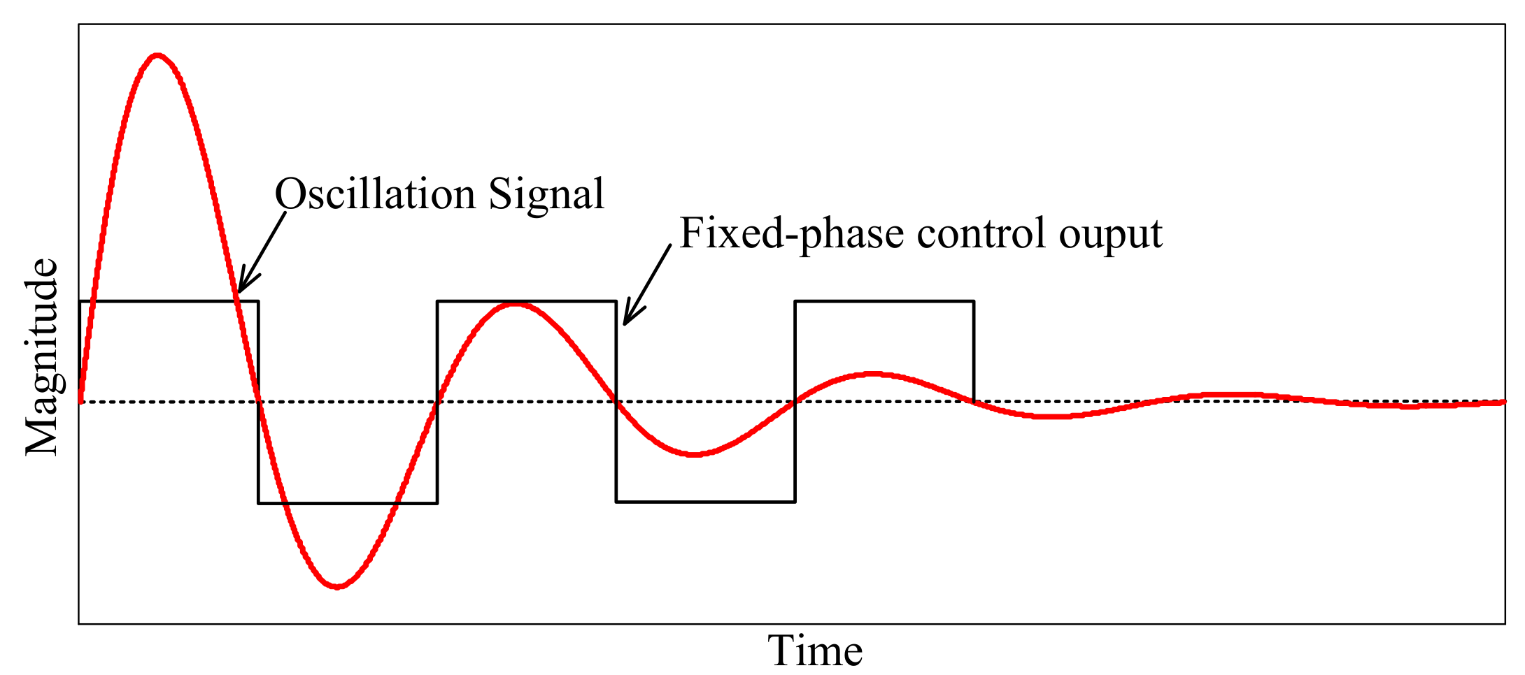
2.3. Oscillation Damping Controls

For DFIG, the damping control signal can be added to the reactive power control loop or active power control loop [17]. For active power modulation based damping control, the active power is directly related to the electromagnetic torque, and it may cause the torsional oscillation [11]. By contrast, the reactive power is determined by the converter, which is not related to the electromagnetic torque, so it will not interact with torsional oscillation. Usually, reactive power modulation of DFIG can be achieved via reactive power feedback control or voltage feedback control schemes. While both of the control schemes are feasible, their effectiveness may differ, and there has not been a systematic comparison between them. This study investigates the difference between the two schemes for inter-area oscillation damping control and provides a deeper insight into the controller design.
Figure 3a,b describes the feedback control scheme and the related damping control loop of reactive and voltage control method, respectively.
The reactive power control and voltage control are achieved by using two PI control loops, as shown in Figure 3c, which are commonly used for DFIG reactive power modulation [9,12,18].
In this paper, the fixed-phase damping control is employed to study the damping contribution of the two feedback schemes. The reason for selecting fixed-phase damping control is that it only needs the oscillation frequency and keeps the phase contrary to the input oscillation signal. Therefore, the damping contribution comparison in this paper can focus on the two different reactive power control schemes without the interference from damping controller parameters. For such damping control, the reactive power (or voltage) reference value of DFIG is changed to its maximum/minimum value in the same step with the changing rate of oscillation signals.
If the power oscillation in the inter-area transmission line is:
P c r = A c r e σ c r t c o s ( ω c r t + φ c r ) .
Then, the DFIG reactive modulation signal should be:
Q r e f = Q m o u s i g n ( c o s ( ω c r t + φ c r + φ l e a d + π 2 ) ) .
This requires the switching time of DFIG reactive power to be in the same step with the frequency of the power oscillation associated with the critical oscillation mode, so that the maximum damping level can be archived in order to damp the critical mode.
The principle of the fixed-phase controller is shown in Figure 4. It requires the switching time of DFIG reactive power to be in the same step with the frequency of the power oscillation associated with the critical oscillation mode. The transmission power, which is suggested and verified to be one of the most effective control signal to the damping controller [19,20], is selected as the input signal for damping control in this paper.
To investigate the differences between these two feedback control methods, the system should operate at the same condition. For the normal operation condition, the output reactive power of DFIG is set to 50% of the DFIG reactive power capacity. Thus, the rated reactive power for reactive power feedback control loop is 50% of the DFIG reactive power capacity and the corresponding rated voltage for the voltage feedback control loop is 1.079 p.u. The modulated reactive power for damping control is ±10% of the DFIG rated reactive power capacity. Therefore, the modulation range is ±10% for reactive feedback control and ±0.023 p.u. for voltage feedback control.

3. Comparison Analysis

In this section, the differences of damping contribution between reactive power feedback control and voltage feedback control are systematically compared through frequency domain analysis, μ -analysis based robustness analysis and time-domain simulation. The frequency domain analysis can evaluate the damping contribution of the controller with respect to the oscillation frequency. The μ -analysis utilizes the structured singular value theory to assess the robustness to the system operation point and wind speed uncertainty.

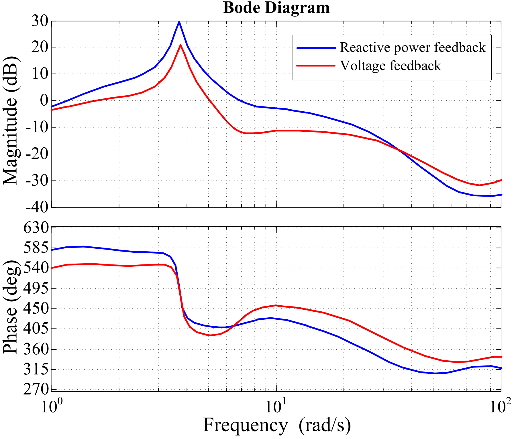
3.1. Frequency Domain Analysis
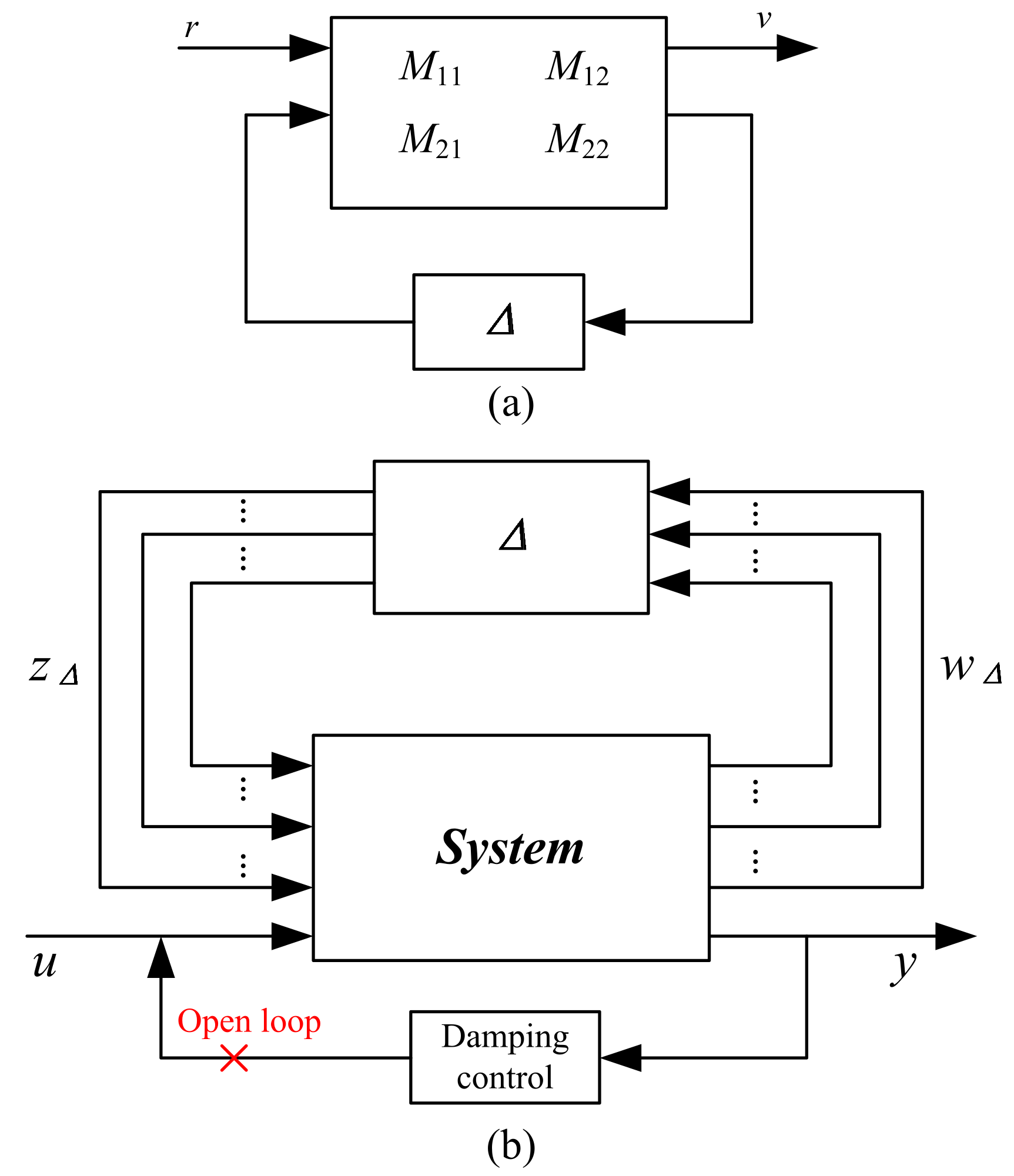
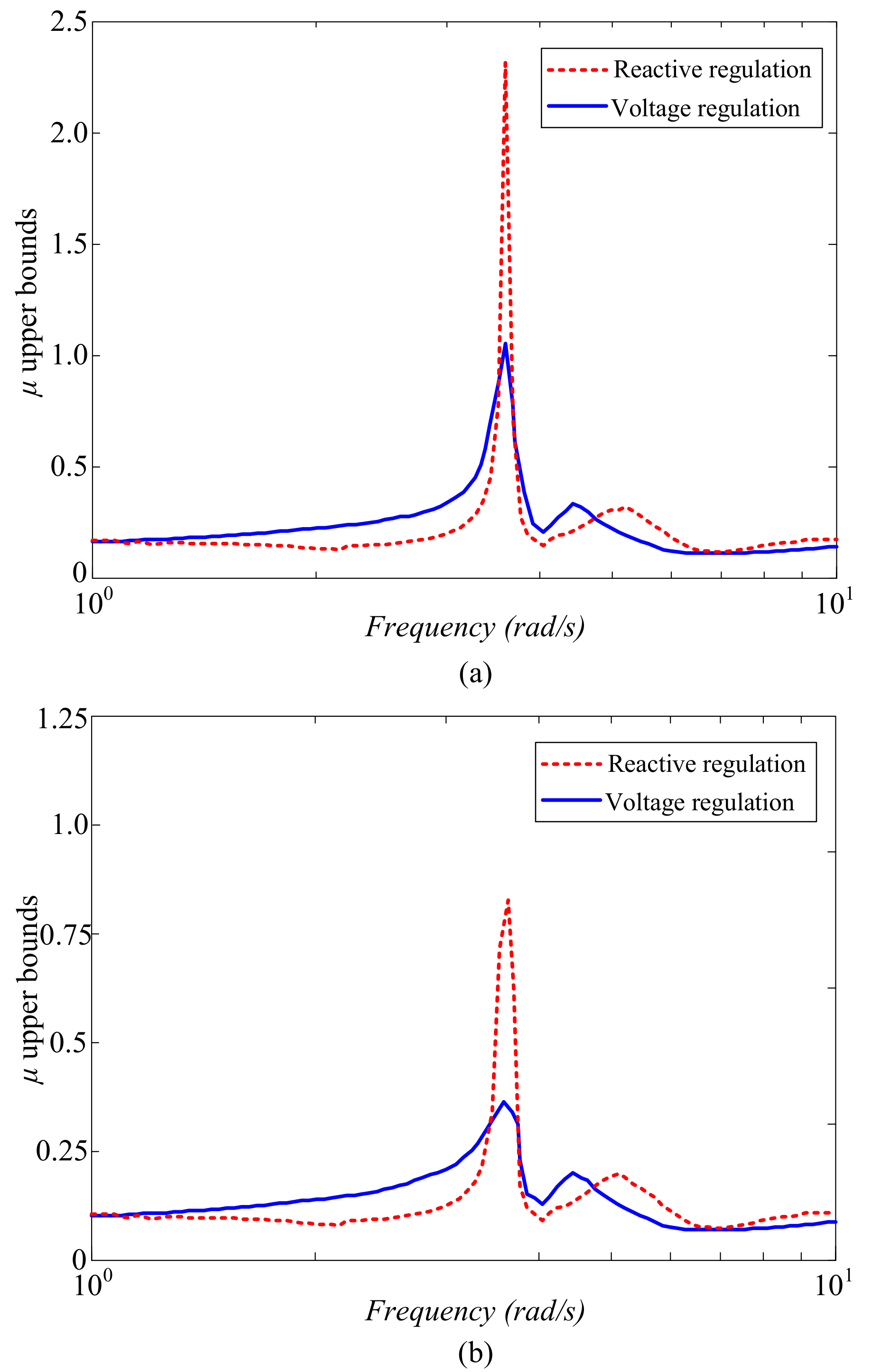
The frequency domain analysis is based on the dynamic model of the system. For the transmission power between area I and area II, the open loop frequency response from the reactive power control and voltage control are compared in Figure 5 using the time-based linearization toolbox in Matlab (2012Ra) [21]. These bode plot diagrams show the different magnitudes in the situation of voltage feedback control loop and of reactive power feedback control loop. When the oscillation frequency is 3.72 rad/s, it can be seen that the reactive power feedback control loop has a larger magnitude than the voltage feedback control loop for damping control. The main parameters of the two different control loops are the PI parameters shown in Figure 3c. For the DFIG reactive power modulation, the PI control should keep the system maintaining stability. The study in [22] shows that the acceptable region of K p 1 and K i 1 are 0.01–5, 0.1–30, respectively, both for the control loop of reactive power feedback and voltage feedback. To investigate the impact of the two key parameters, the magnitude of the bode plot diagram with the oscillation frequency are listed in Table 1 and Table 2.
As shown in Table 1 and Table 2, K p 1 has very limited influence on the magnitude of oscillation frequency in bode diagram, no matter with the reactive power feedback loop or the voltage feedback loop. On the other hand, K i 1 has a greater influence on the magnitude. However, when the value goes below 10, the magnitude changes obviously. When the value becomes larger, the influence is not so obvious. The data in these two tables also show that, with the same control parameters, the magnitude of reactive power feedback is higher than the one of voltage feedback, which means that reactive power feedback control shows a better damping. In the subsequent study (including the results in Figure 5), the value of K p 1 and K i 1 are selected as 0.5 and 10, respectively.

3.2. Robustness Analysis Based on μ -Analysis

Generally, the controller for power system is designed based on a selected operating point. However, the system operates over a wide range of operating conditions in practice. Thus, the robustness of controller should be evaluated. Recently, many robust control algorithms have been applied to power system controller design, in which the structured singular value theory [23] is a popular approach to analyze the robustness of damping controllers and is used in this paper.
Figure 6a shows the general framework for robustness analysis. This analysis is based on the linear fraction transformation (LFT), which is an effective and flexible approach to represent uncertainties in systems and matrices.
In Figure 6a, M C ( p 1 + p 2 ) × ( q 1 + q 2 ) represents the system complex transfer matrix. Δ m a t h b b C q 1 × q 2 represents the system uncertainties. The relationship between r and v can be described as:
v = [ M 11 + M 12 Δ ( I M 22 Δ ) 1 M 21 ] r = F l ( M , Δ ) r .
The notation F l indicates that the lower loop of M is closed with Δ .
All the sources of uncertainty, such as parametric uncertainties or unmolded dynamics, are included in the uncertain matrix Δ . The transfer matrix Δ can be formed as:
Δ = d i a g [ δ 1 I r 1 , , δ s I r s , Δ 1 , , Δ F ] .
For the interconnected system represented in Figure 6a, the structured singular value μ is defined as the smallest structured uncertainty Δ [24], measured in terms of its maximum singular value σ ¯ , which makes d e t ( I M Δ ) = 0 :
μ ( M ) 1 : = m i n σ ¯ ( Δ ) : Δ Δ , d e t ( I M Δ ) = 0 .
If there is no such structure, then μ ( M ) = 0 . The μ 1 is used to assess the robust stability level.
In this paper, the μ -analysis is utilized to investigate the system robustness with uncertainties in wind speed and the ranging of operation points. The changing of system operating conditions can be equivalent with a structured perturbation model of the linearized power system. For a power system with m uncertain parameters ( δ 1 , , δ m ) , the linear state space model can be obtained as follows [24]:
x ˙ ( t ) y ( t ) = A 0 + i = 1 n δ i A i B 0 + i = 1 n δ i B i C 0 + i = 1 n δ i C i D 0 + i = 1 n δ i D i x ( t ) y ( t ) .
In Equation (23), A 0 , B 0 , C 0 , and D 0 represent the linear state space matrices of the power system without uncertainty. Matrices A i , B i , C i , and D i represent the system uncertainties and the perturbations δ i are normalized. For robustness analysis, the linear state space uncertainties in Equation (23) should be transformed to the LFT form as [25]:
x ˙ u z 1 z m = A 0 B 0 E 1 E m C 0 D 0 F 1 F m G 1 H 1 0 0 G m H m 0 0 x u ω 1 ω m .
With this transformation, the uncertainties caused by operation conditions are represented by parameter uncertainties. Additionally, the uncertainties of wind power generation is considered as well.
To investigate the robustness of reactive power feedback control and voltage feedback control for damping control, the introduced structured singular value theory is employed. The proposed comparison framework for the robustness of the two different feedback controls is shown in Figure 6b. In the robustness analysis, both the changes of operating point and wind speed are considered.
As shown in Figure 6b, the robustness analysis consists of two components: linear state space matrixes uncertainty Δ (include system operating uncertainty and wind sped uncertainty) and fixed phase damping controller. The analysis includes both the open loop and closed loop of damping control.
The μ -analysis results of two open loop systems—(1) with reactive power feedback control and (2) with voltage feedback control—are shown in Figure 7a. The μ -analysis results for two closed loop system are shown in Figure 7b.
As shown in Figure 7a,b, the μ -analysis results show two distinctive peaks corresponding to the two system oscillation modes, one is the inter-area mode and the other one is the local mode. The system without damping control is not robustly stable due to the μ bounds at the inter-area mode is larger than 1. The μ bounds of the system with reactive power feedback control is higher than the one with voltage feedback control, which means that the voltage feedback control scheme shows a better robustness with respect to the operation point and wind speed uncertainty.

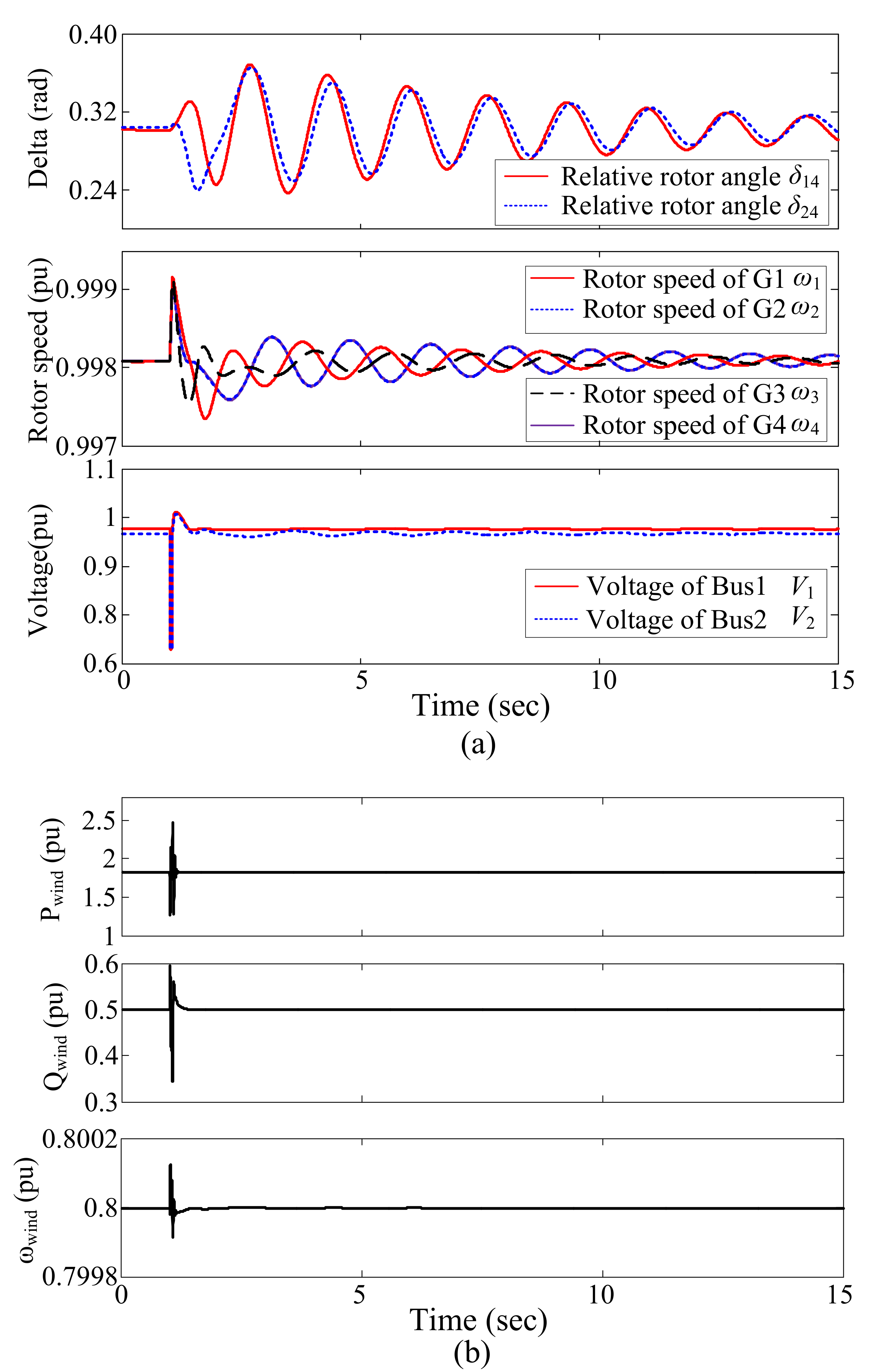
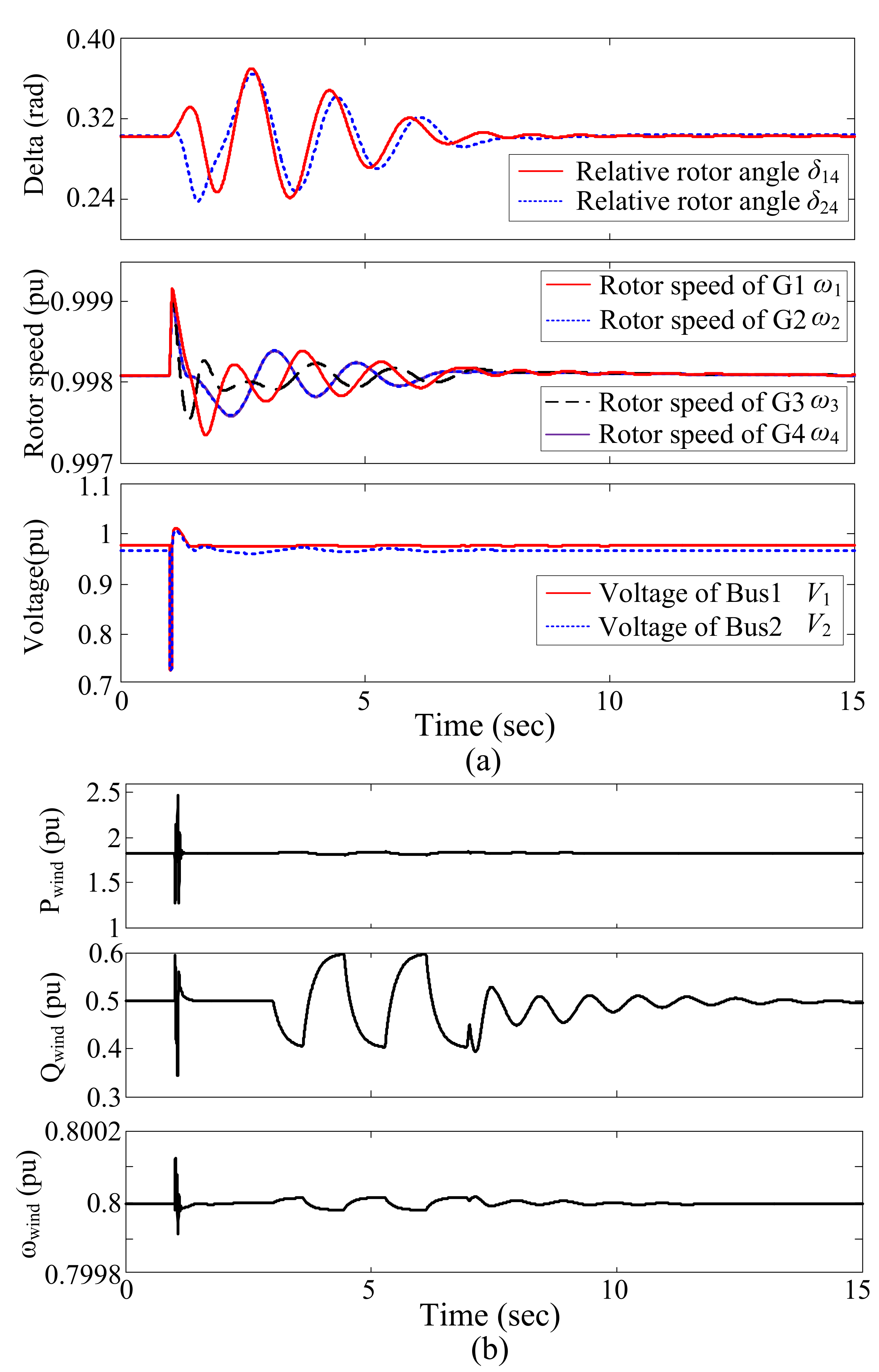
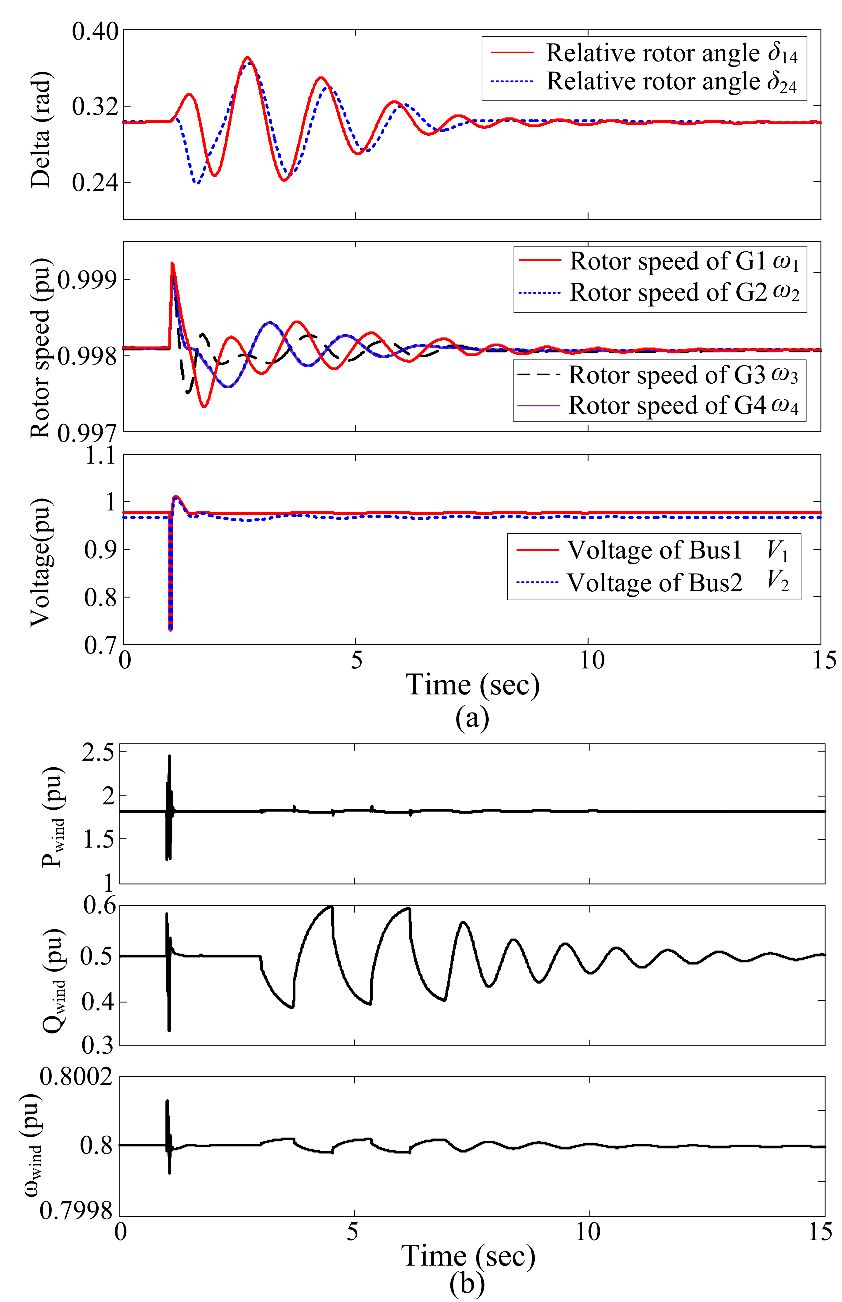
3.3. Time Domain Analysis

Time-domain simulations are performed to examine the damping performance between the reactive power feedback and voltage feedback control. A three-phase short circuit occurs at the midpoint of the interconnection transmission line at t = 1 . 0 s and is last for 0.1 s. The active power transporting between the two areas is chosen as input signal of the fixed phase damping controller in this simulation. Three cases—without damping controller, with an additional damping controller in reactive power feedback control, and with an additional damping controller in voltage feedback control—are simulated to enable the comparison.
Figure 8 plots the system dynamics including the machines and DFIG with no damping control added to DFIG. In Figure 8a, the relative angle difference, rotor speed, and bus voltage are plotted. The active power, reactive power and rotor speed of the DFIG are plotted in Figure 8b. As shown in Figure 8b, when the disturbance occurs, the reactive and active power of DFIG keep constant after a temporary transient. The output of DFIG is decoupled from the grid. Therefore, it can not provide any support for the power system oscillation damping. In this case, the low-frequency inter-area oscillations last a long time with the amplitude decrease slow when in the case of no damping control adding to DFIG.
For the DFIG with reactive power feedback control, the modulated reactive power reference value for damping control is ±10%. For the DFIG with voltage feedback control, the modulated voltage reference value for damping control is ±0.023 p.u. The fixed phase damping controller is active at t = 3 . 0 s and disconnected at t = 7 . 2 s.
Figure 9 shows the system dynamic responses when the reactive power feedback is used for DFIG reactive power modulation and the fixed phase damping controller is added to the reactive power feedback control loop. As shown in Figure 9b, the reactive power output of DFIG is various against the power system oscillations. The DFIG reactive power output is coupled with system inter-area oscillation with the additional damping controller loop. Compared with the results given in Figure 8, the system inter-area oscillations are damped quicker. This result illustrates that the system damping can be significantly enhanced when the damping controller added to the DFIG reactive power control loop.
Figure 10 depicts the dynamic responses of the system when the voltage feedback is used for DFIG reactive power modulation and the fixed phase damping controller adds the voltage feedback control loop. In this case, the DFIG will participate in the power system oscillation damping control by modulating its reactive power output, as shown in Figure 10b. However, in this case, the feedback control is not the reactive power but the terminal bus voltage. To compare the damping contribution under the same condition, the reactive power of DFIG is maintained at 50% until the damping control is active. The simulation results show that system oscillation can be dampened quickly as well. However, compared with the reactive feedback control loop, as the results given in Figure 9, the voltage feedback control loop provides a relatively lower damping level.
As the fixed phase damping controller begins to be active at the same time, the damping control integrated with the reactive power feedback control loop shows better damping results than the voltage feedback control loop under the same reactive power modulation level as shown in Figure 10b and Figure 11b.
To compare the different damping results from two different reactive power control loops, Figure 11 depictes the transmission power between area I and area II. As shown in Figure 11, the damping control via reactive feedback control loop can damp the system oscillation quickly because the amplitude of oscillation power reduced on a larger scale. This simulation results are consistent with the results in frequency domain analysis. The bode plot in Figure 4 also demonstrates that the damping control via reactive power feedback control loop can provide more damping.
It is also worth mentioning that, as the fault occurs, the bus voltage changes and the output reactive power of DFIG will respond to the change when the voltage feedback control is used. Contrarily, the reactive power feedback control cannot respond to the system fault because the output reactive power of DIFG is hardly influenced by the system fault. Thus, when the voltage feedback control is used, the reactive power of DFIG will change with the swing of voltage caused by the fault. The changed reactive power will provide damping to the system oscillation as shown in case 4 in Figure 11.

4. Conclusions

This paper conducts a comparative analysis on the performance of DFIG reactive power and voltage feedback control for inter-area oscillation damping control. The reactive power regulation and voltage regulation are all executed according to the control of DFIG output reactive power. In this study, the fixed-phase damping control, called bang-bang modulation, is employed to examine the performance of these two feedback control methods. The two-area four-machine system, along with a DFIG-based wind generation, is the platform to demonstrate the analysis results from the frequency domain and time domain. The evaluation of the control schemes’ robustness by altering the operation conditions of systems and wind speed is also studied.
The analysis in frequency domain, using bode plot technicals, show that the reactive power feedback control scheme can provide better damping when the additional damping control was required. The time domain simulation results also show that the damping control via reactive power feedback control loop can damp the system oscillation faster. However, the μ -analysis results show that voltage feedback control conditions are more robust to the system operation point uncertainty than the reactive power feedback control.
The results obtained in this paper can provide a practical guide for controller design for DFIG reactive modulation against inter-area oscillations.

Acknowledgments

This work is partly supported by the Fundamental Research Funds for the Central Universities, Nos 2017NZYQN47 and 2017NZYQN46, and partly supported the Open Research Subject of Signal and Information Processing Key Laboratory of Sichuan Province, Nos SZJJ2016-094.

Author Contributions

Kai Liao performed the theoretical analysis; Yao Wang performed the time-domain simulation.

Conflicts of Interest

The authors declare no conflict of interest.

Appendix A

The main parameters of synchronous generators in this study are shown in Table A1. The parameters of DFIG are listed in Table A2. K 1 , K 2 , K 3 , K 4 and K 5 are the parameters of the PI controller of the outer active power loop, the inner q-axis current loop, the outer reactive power loop, the outer voltage loop and the inner d-axis current loop, respectively. Subscripts p and i are the proportion and integration, respectively.
Table A1. Parameters of the synchronous generator [9].
Symbol Value Symbol Value
r s 0.003 X l s 0.19
X q 1.8 X d 1.7
r k q 1 0.00178 r f d 0.000929
X l k q 1 0.8125 X l f d 0.11414
r k q 2 0.00841 r k d 0.01334
X l k q 2 0.0939 X l k d 0.0812
Table A2. Parameters of Doubly Fed Induction Generator (DFIG) (p.u.).
Symbol Value Symbol Value
Stator resistance R s 0.007Stator self-reactance L s 0.18
Rotor resistance R r 0.005Rotor self-reactance L r 0.156
K p 1 1 K i 1 100
K p 2 0.05 K i 2 5
K p 3 1 K i 3 100
K p 4 0.002 K i 4 0.05
K p 5 0.3 K i 5 5
Transfer function of PSS installed on generator 1:
H ( s ) = 100 s 1 + 10 s 1 + 0 . 05 s 0 . 2 s

References

  1. Yao, J.; Li, H.; Chen, Z.; Xia, X.; Li, X.Q.; Liao, Y. Enhanced control of a DFIG-based wind-power generation system with series grid-side converter under unbalanced grid voltage conditions. IEEE Trans. Power Electron. 2013, 28, 3167–3181. [Google Scholar] [CrossRef]
  2. Boutoubat, M.; Mokrani, L.; Machmoum, M. Control of a wind energy conversion system equipped by a DFIG for active power generation and power quality improvement. Renew. Energy 2013, 50, 378–386. [Google Scholar] [CrossRef]
  3. Edrah, M.; Lo, K.L.; Anaya-Lara, O. Impacts of high penetration of DFIG wind turbines on rotor angle stability of power systems. IEEE Trans. Sustain. Energy 2015, 6, 759–766. [Google Scholar] [CrossRef]
  4. Domínguez-García, J.L.; Gomis-Bellmunt, O.; Bianchi, F.D.; Sumper, A. Power oscillation damping supported by wind power: A review. Renew. Sustain. Energy Rev. 2012, 16, 4994–5006. [Google Scholar] [CrossRef]
  5. Hughes, F.M.; Anaya-Lara, O.; Jenkins, N.; Strbac, G. A power system stabilizer for DFIG-based wind generation. IEEE Trans. Power Syst. 2006, 21, 763–772. [Google Scholar] [CrossRef]
  6. Mishra, Y.; Mishra, S.; Tripathy, M.; Senroy, N.; Dong, Z.Y. Improving stability of a DFIG-based wind power system with tuned damping controller. IEEE Trans. Energy Convers. 2009, 24, 650–660. [Google Scholar] [CrossRef]
  7. Wickramasinghe, A.; Perera, S.; Agalgaonkar, A.; Meegahapola, L. Synchronous mode operation of DFIG based wind turbines for improvement of power system inertia. Renew. Energy, 2016, 95, 152–161. [Google Scholar] [CrossRef]
  8. Tsourakis, G.; Nomikos, B.M.; Vournas, C.D. Contribution of doubly fed wind generators to oscillation damping. IEEE Trans. Energy Convers. 2009, 24, 783–791. [Google Scholar] [CrossRef]
  9. Mishra, Y.; Mishra, S.; Li, F.; Dong, Z.Y.; Bansal, R.C. Small-Signal Stability Analysis of a DFIG-Based Wind Power System Under Different Modes of Operation. IEEE Trans. Energy Convers. 2009, 24, 972–982. [Google Scholar] [CrossRef]
  10. Mithulananthan, N.; Canizares, C.; Reeve, J.; Rogers, G. Comparison of PSS, SVC, and STATCOM controllers for damping power system oscillations. IEEE Trans. Power Syst. 2003, 18, 786–792. [Google Scholar] [CrossRef]
  11. Fan, L.; Yin, H.; Miao, Z. On Active/Reactive Power Modulation of DFIG-Based Wind Generation for Interarea Oscillation Damping. IEEE Trans. Energy Convers. 2011, 26, 513–521. [Google Scholar]
  12. Hansen, A.D.; Srensen, P.; Iov, F.; Blaabjerg, F. Control of variable speed wind turbines with doubly-fed induction generators. Wind Eng. 2004, 28, 411–434. [Google Scholar] [CrossRef]
  13. Yang, L.; Xu, Z.; Ostergaard, J.; Dong, Z.Y.; Wong, K.P. Advanced control strategy of DFIG wind turbines for power system fault ride through. IEEE Trans. Power Syst. 2012, 27, 713–722. [Google Scholar] [CrossRef]
  14. Mei, F.; Pal, B.C. Modeling and Small Signal Analysis of a Grid Connected Doubly Fed Induction Generator. In Proceedings of the IEEE PES General Meeting, San Francisco, CA, USA, 16 June 2005; pp. 358–367. [Google Scholar]
  15. Singh, M.; Allen, A.J.; Muljadi, E.; Gevorgian, V.; Zhang, Y.; Santoso, S. Interarea oscillation damping controls for wind power plants. IEEE Trans. Sustain. Energy 2015, 6, 967–975. [Google Scholar] [CrossRef]
  16. Tang, Y.; He, H.; Wen, J.; Liu, J. Power system stability control for a wind farm based on adaptive dynamic programming. IEEE Trans. Smart Grid 2015, 6, 166–177. [Google Scholar] [CrossRef]
  17. Fernandez, R.; Mantz, R.; Battaiotto, P. Contribution of wind farms to the network stability. In Proceedings of the IEEE Power Energy Society General Meeting, Montreal, QC, Canada, 18–22 June 2006. [Google Scholar]
  18. Muller, S.; Deicke, M.; de Doncker, R.W. Doubly fed induction generator systems for wind turbines. IEEE Ind. Appl. Mag. 2002, 8, 26–33. [Google Scholar] [CrossRef]
  19. Larsen, E.; Sanchez-Gasca, J.; Chow, J. Concepts for design of FACTS controllers to damp power swings. IEEE Trans. Power Syst. 1995, 10, 948–956. [Google Scholar] [CrossRef]
  20. Fan, L.; Feliachi, A.; Schoder, K. Selection and design of a TCSC control signal in damping power system inter-area oscillations for multiple operating conditions. Electr. Power Syst. Res. 2002, 62, 127–137. [Google Scholar] [CrossRef]
  21. MATLAB Help Tutorial, Version 7.8.0.347. The Math Works: Natick, MA, USA, 2009. Available online: http://www.mathworks.com/help/toolbox/physmod/powersys/ref/windturbinedoublyfedinductiongeneratorphasortype.html (accessed on 4 June 2017).
  22. Wu, F.; Zhang, X.P.; Godfrey, K.; Ju, P. Small signal stability analysis and optimal control of a wind turbine with doubly fed induction generator. IET Gener. Transm. Distrib. 2007, 1, 751–760. [Google Scholar] [CrossRef]
  23. Skogestad, S.; Postlethwaite, I. Multivariable Feedback Control-Analysis and Design; Wiley: New York, NY, USA, 1996. [Google Scholar]
  24. Doyle, J.C. Analysis of feedback systems with structured uncertainties. IEE Proc. D 1982, 129, 242–250. [Google Scholar] [CrossRef]
  25. Morton, B.; McAfoos, R. A μ-test for Robustness Analysis of a Real-Parameter Variation Problem. In Proceedings of the American Control Conference, Boston, MA, USA, 19–21 June 1985; pp. 135–138. [Google Scholar]
Figure 1. The structure of the study system.
Energies 10 01206 g001
Figure 2. Schematic diagram of doubly fed induction generator (DFIG) based wind energy conversion system.
Energies 10 01206 g002
Figure 3. Schematic diagram of rotor side control. (a) schematic diagram of reactive power feedback control; (b) schematic diagram of voltage feedback control; (c) schematic diagram of inner PI controller and outer PI controller for reactive power and voltage feedback control.
Energies 10 01206 g003
Figure 4. A diagram of the fixed-phase damping controller.
Energies 10 01206 g004
Figure 5. The bode diagram of reactive power feedback control and voltage feedback control.
Energies 10 01206 g005
Figure 6. (a) Framework for robust stability analysis; (b) the uncertain model for power system.
Energies 10 01206 g006
Figure 7. The uncertain bounds of reactive power regulation and voltage regulation. (a) Open loop; (b) close loop.
Energies 10 01206 g007
Figure 8. System dynamic performances without additional damping control for DFIG. (a) Generators dynamics, from up to bottom: δ 14 and δ 24 , rotor speeds of the generators, buses voltage; (b) DFIG dynamics, from top to bottom: active power of DFIG, reactive power of DFIG, and rotor speed of DFIG.
Energies 10 01206 g008
Figure 9. System dynamic performances with damping controller added to reactive power feedback control loop. (a) Generators dynamics, from top to bottom: δ 14 and δ 24 , rotor speeds of the generators, buses voltage; (b) DFIG dynamics, from top to bottom: active power of DFIG, reactive power of DFIG, and rotor speed of DFIG.
Energies 10 01206 g009
Figure 10. System dynamic performances with damping controller added to voltage feedback control loop. (a) Generators dynamics, from top to bottom: δ 14 and δ 24 , rotor speeds of the generators, buses voltage; (b) DFIG dynamics, from top to bottom: active power of DFIG, reactive power of DFIG, and rotor speed of DFIG.
Energies 10 01206 g010
Figure 11. Transmission power between area I and area II. Case 1 corresponding to without damping controller; Case 2 and Case 3 corresponding to the damping controller with reactive power feedback and voltage feedback control scheme active at the same time, respectively; Case 4 corresponding to the voltage feedback control scheme with damping controller.
Energies 10 01206 g011
Table 1. The oscillation frequency and its magnitude with the ranging of K p 1 .
Control Scheme K p 1 0.050.10.150.20.511.55
Reactivef3.723.723.723.723.723.723.723.72
Power FeedbackMagnitude27.827.827.627.827.727.827.627.9
Voltagef3.743.743.743.743.743.743.743.74
FeedbackMagnitude21.321.221.321.421.321.321.221.4
Table 2. The oscillation frequency and its magnitude with the ranging of K i 1 .
Control Scheme K i 1 125810152030
Reactivef3.723.723.723.723.723.723.723.72
Power FeedbackMagnitude15.420.525.026.227.727.827.627.9
Voltagef3.743.743.743.753.743.743.753.75
FeedbackMagnitude6.911.518.920.621.322.121.822.3

