
Power Balancing Control for Grid Energy Storage System in Photovoltaic Applications—Real Time Digital Simulation Implementation


 ,
,  and
and 
Abstract
:1. Introduction
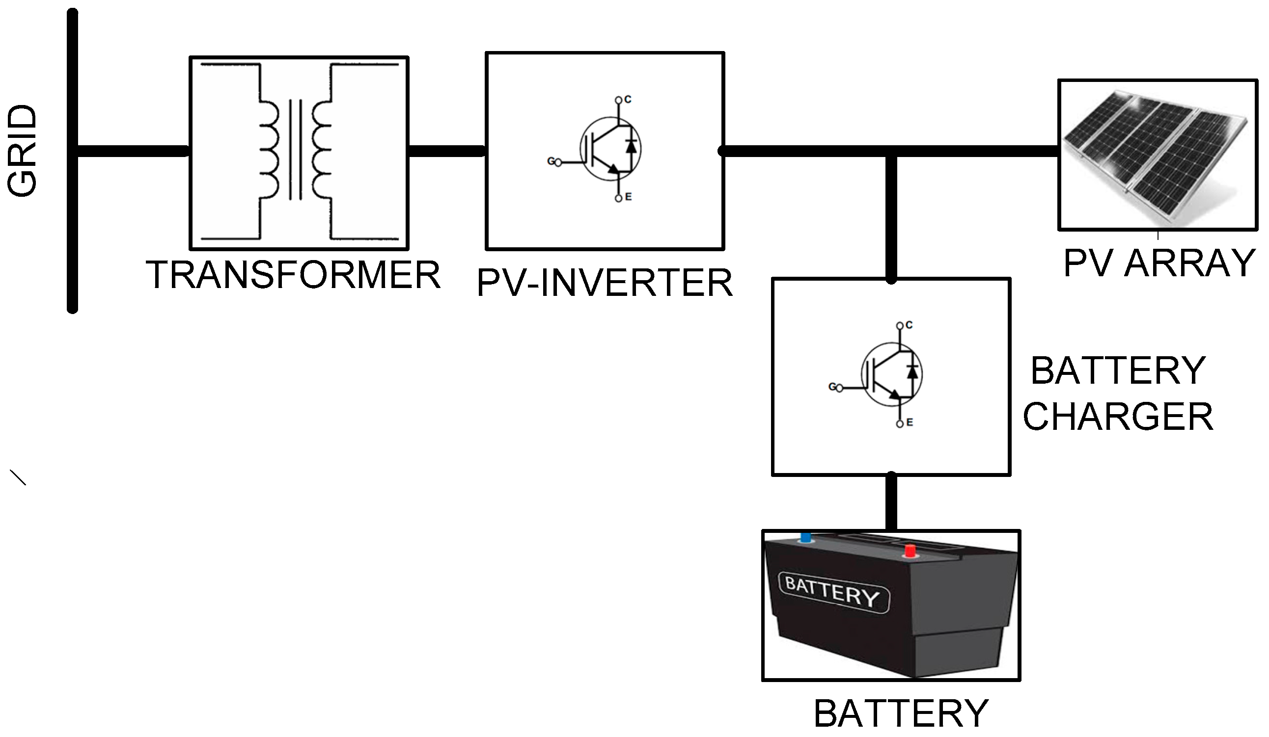
- Mode1:
- During the daytime, the PV array feeds active power to the grid through an inverter and provides charging current to the battery through the battery charger.
- Mode2:
- The battery is in charged condition and the PV array cannot feed full power to the grid i.e., during partial cloudiness or during nighttime or when the solar irradiation is weak. In this mode of operation, PV array feeds the power to the grid based on maximum power point (MPP) and the batteries also feed active power to the grid.
- Mode3:
- The battery is in fully discharged state and the PV array cannot provide the charging current to the battery i.e., during nighttime. In this mode of operation, the grid provides the charging current to the batteries through the inverter and battery charger.
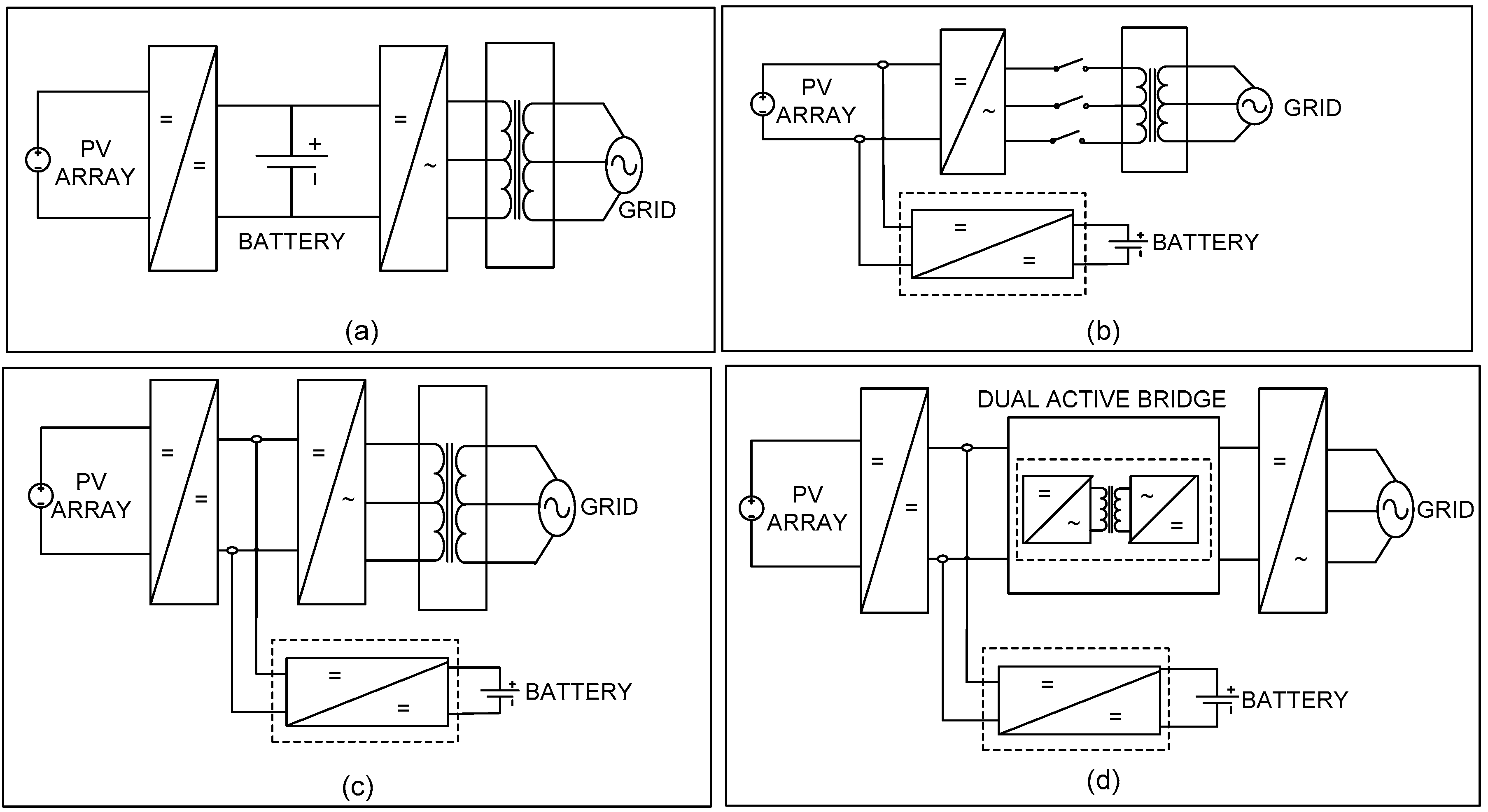
- The battery charger only needs to be designed for the battery capacity.
- Independent controls for the battery charger and inverter are possible.
- When the system operates in Mode3, the inverter acts like a simple diode rectifier and the battery charger takes care of the charging current.
- The high-frequency transformer in the DAB provides isolation between the PV array and the battery.
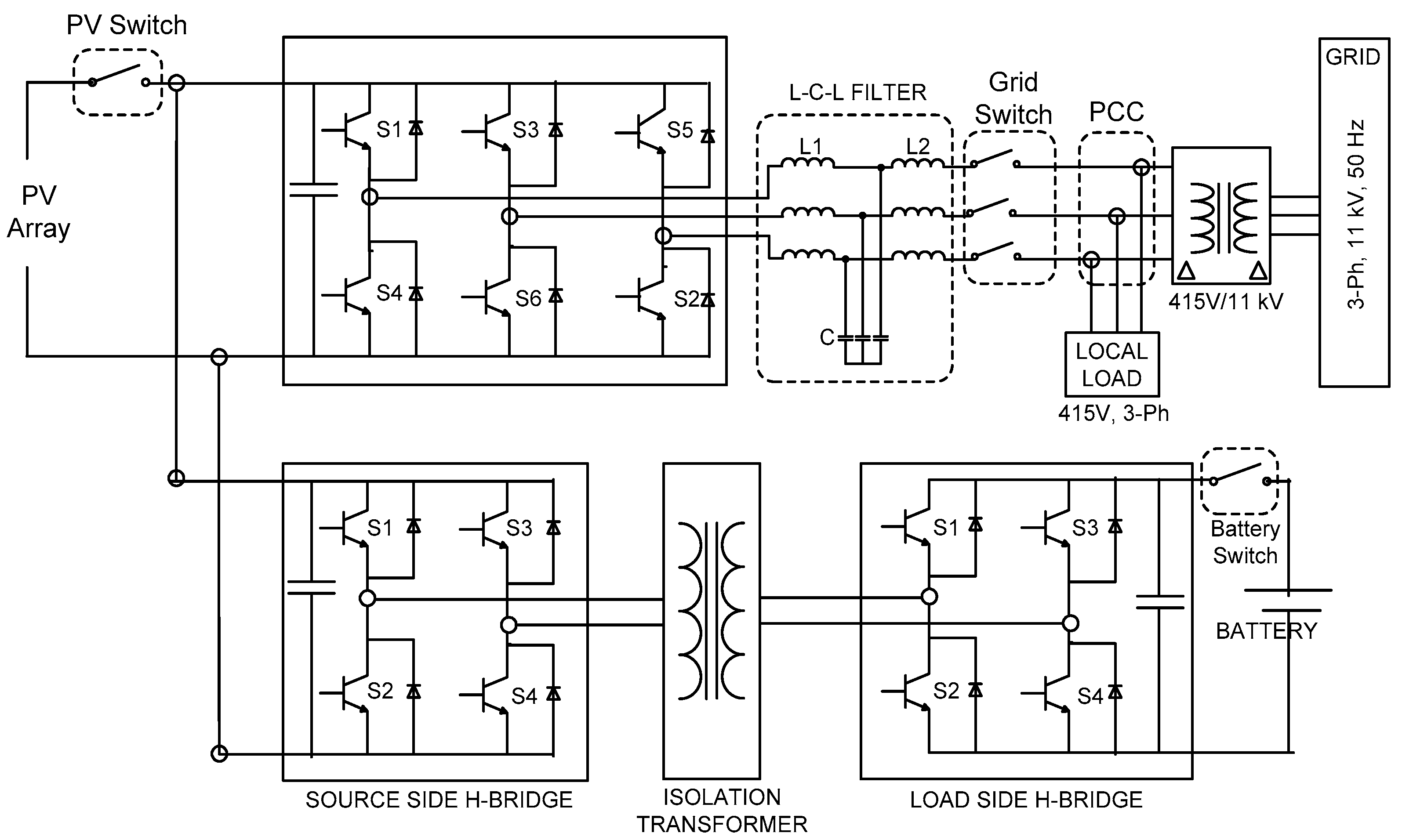
2. Dual Active Bridge Based Energy Storage System for Photo Voltaic Applications
2.1. Design Calculations for the Photo Voltaic-Inverter
2.2. Selection of Battery Type
2.3. Selection of the PV Array
2.4. Design Calculations for the Battery Charger
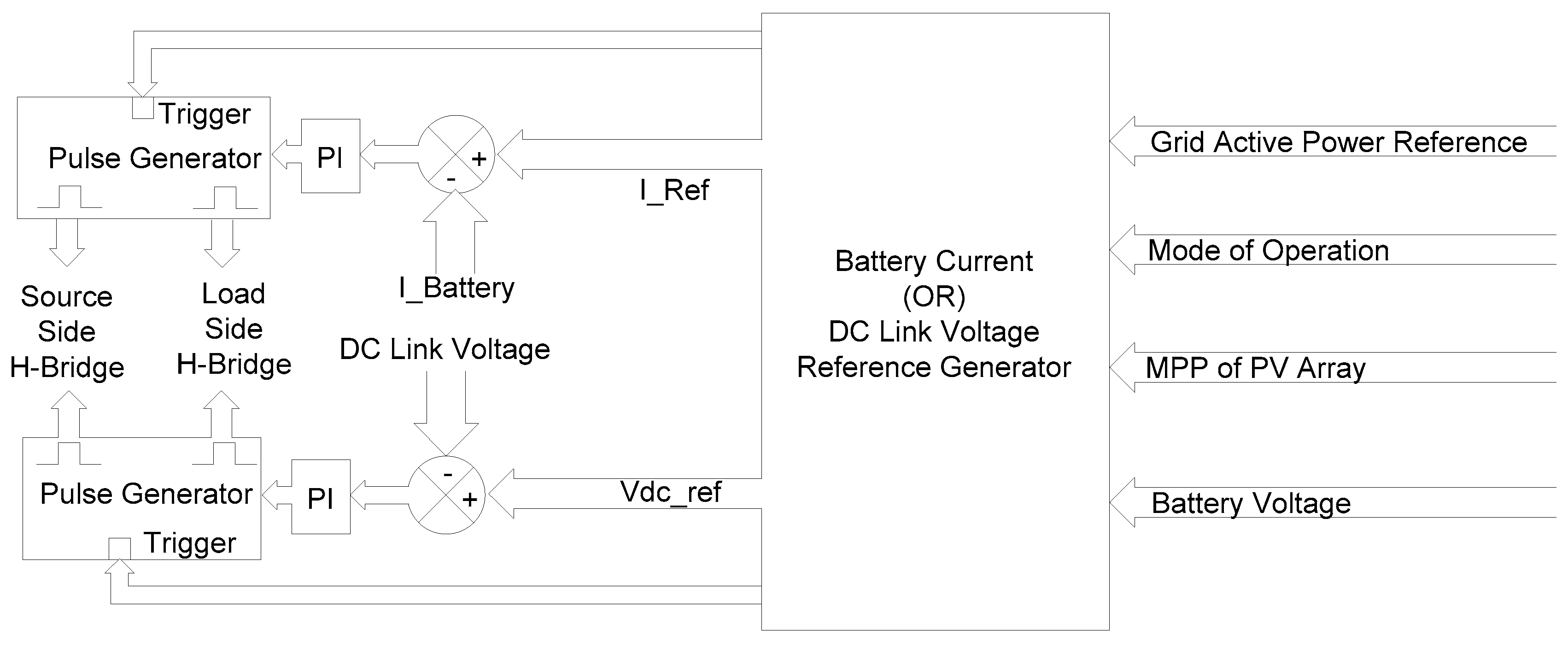
2.5. Control of the Dual Active Bridge-Based Battery Charger
- (1)
- Inputs to the reference generator block are the mode of operation, MPP of the PV array, active power reference, and battery voltage signals.
- (2)
- When the system is operating in either Mode1 or Mode3:
- The battery is in charging mode of operation hence the battery current reference is taken as positive.
- Based on the battery SOC, the reference charging current is obtained through a look-up-table.
- When the battery SOC is in the range of 80 to 115%, then the battery charging current is maintained at 0.12 C i.e., 36 A (0.12 * amp-hour rating of battery) as shown in Table 3.
- When the battery is fully charged, then the battery voltage will reach the maximum voltage, then the reference battery current is made zero to avoid overcharging. In this case, the operation can be transferred to Mode2, if the load requirement is more than the PV power.
- When the battery is fully discharged, then the battery voltage will be less than 0.9 times the nominal voltage, then the charging current is adjusted to 0.2 C i.e., 57 A for fast charging.
- (3)
- When the system is operating in Mode2:
- In this mode, the battery is in discharging mode of operation hence the battery current reference is taken as negative.
- In this case, if the PV array is in an inactive state i.e., PV voltage is more than the minimum DC link voltage required (i.e., 620 V) but the MPP of the PV array is less than the critical load requirement:
- ○
- The battery discharging current is obtained from the Amp-hour rating of the battery and the discharging time.
- ○
- Since the minimum backup time in this system is 4 h, the user can adjust the backup time to be more than 4 h.
- In case the PV voltage is less than the minimum DC link voltage required then the battery charger needs to provide the required voltage to the DC link:
- ○
- In this case, the DC link voltage reference (Vdc_ref) is generated by the reference generator.
- ○
- Vdc_ref is always maintained at more than the minimum required DC link voltage (620 V).
2.6. Control of the Grid-Connected Photo Voltaic Inverter
- (a)
- Initially, When the system starts the PV power (Ppv) = 0
- ○
- In this state, PV voltage = Voc and the PV current = 0
- ○
- Initialize PV power reference MPP = 0
- ○
- Minimum PV power reference (MPP_Ref_Min) is limited to 0.
- ○
- Maximum PV power reference (MPP_Ref_Max) is limited to 113 kW.
- (b)
- Now increase the PV power reference (MPP) in 500 Watt steps:
- ○
- Measure PV voltage and current and calculate the new PV power (Ppv_New)
- ○
- If Ppv_New is more than Ppv
- ▪
- Ppv == Ppv_New
- ▪
- MPP == MPP + 500 Watt
- ○
- If Ppv_New is less than Ppv
- ▪
- Ppv == Ppv_New
- ▪
- MPP == MPP − 500 Watt
- (c)
- Based on MPP_Ref and battery current, the reference inverter current is obtained.
- (d)
- Steps ‘b’ and ‘c’ operate in a continuous loop.
- (e)
- Since this activity is not required when the solar irradiation is weak, this loop can be bypassed during the nighttime.
2.7. Operation Sequence of the System
- (a)
- During nighttime, the PV voltage is less than the minimum required DC link voltage. Considering that the battery is in discharged mode and being charged from the grid, hence the system is in Mode3.
- (b)
- Now when the irradiation improves in the morning, MPP tracking is started and when the MPP becomes more than the minimum power required for system operations and other critical requirements then the system switches to Mode1.
- (c)
- As the irradiance improves during the daytime, since the battery charging power is almost constant, power transfer to the grid increases.
- (d)
- Again when the irradiation is getting reduced, the power transferred to the grid also reduces.
- (e)
- In case the power requirement for the grid is more than the available PV power, then the system can be transferred manually to theMode2 operation to meet the power demand.
- (f)
- When the irradiation reduces further and becomes zero, then the battery stays in Mode2 till the battery gets discharged and the operation shifts to Mode3 and the process loops back to step (a).
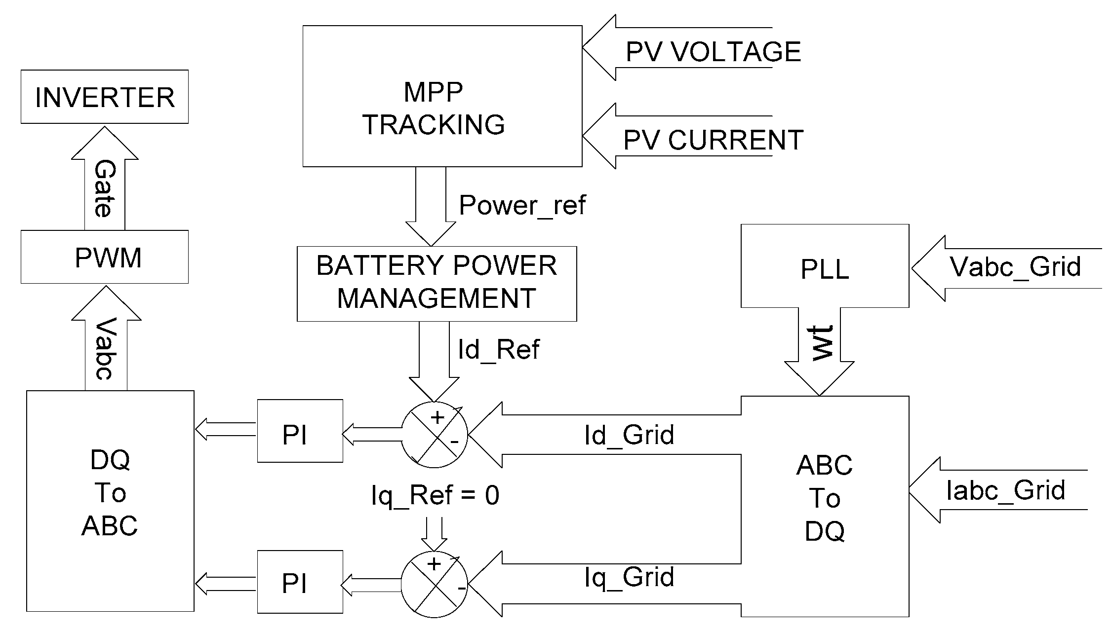
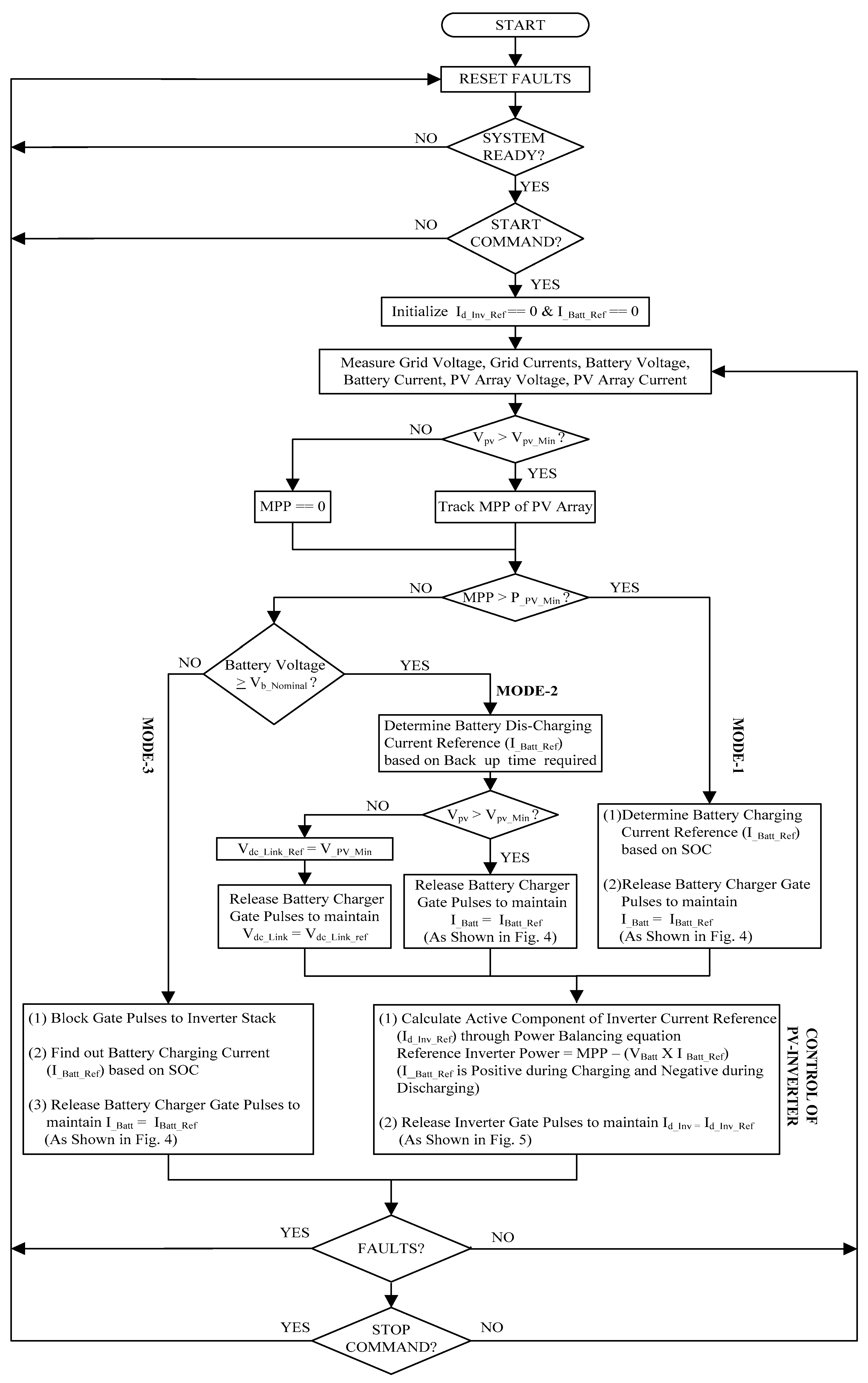
3. Power Balancing Control of the Grid Energy Storage System in Photo Voltaic Applications
- (1)
- Once the system is ready and the start command is given by the user, the controller reads the grid voltages for determining wt through PLL.
- (2)
- The controller initializes the value of the inverter reference current (Id_Inv_Ref) and battery reference currents (I_Batt_Ref) as 0.
- (3)
- The controller reads the PV voltage (Vpv), PV current(Ipv), battery voltage(VBatt) and battery current (I Batt)
- If the PV voltage (Vpv) is less than the minimum PV voltage required (Vpv_Min) then MPP of the PV array is zero. Vpv_Min is the minimum DC required to match the inverter output voltage with the transformer secondary voltage. In this system, 620 V is the minimum DC link voltage required, as shown in Table 2.
- ○
- In this case, if the battery voltage is also less than the nominal battery voltage Vb_Nominal then the system is in Mode3.
- ○
- In this mode, the battery needs to be charged but the PV array cannot provide any power for battery charging, so the grid shall supply the power required for battery charging.
- ○
- In this mode of operation, the inverter acts like a simple diode rectifier to provide DC input to the battery charger.
- ○
- Based on the SOC of battery, the reference battery charging current I_Batt_Ref is obtained.
- If the PV voltage (Vpv) is higherthanthe minimum PV voltage (Vpv_Min) then the controller tracks the MPP of the PV array by monitoring the PV voltage and current.
- ○
- In case the MPP is higher than minimum value i.e., P_PV_Min then the system is in Mode1.
- ○
- In this mode of operation, the battery will be in charging state and the PV array provides the power for battery charging.
- ○
- The remaining power after battery charging will be transferred to the grid.
- ○
- Based on the SOC of the battery, the reference battery charging current I_Batt_Ref is obtained.
- ○
- Through the power balancing equation, the inverter reference current Id_Inv_Ref is calculated based on the MPP and battery current:Inverter power reference = MPP − battery power reference(the battery Power reference is positive during charging mode and negative in discharging mode)
- ⇨
- Inverter Power Reference = MPP − (I_Batt_ref * V_Battery)
- ⇨
- √3 * Vabc_rms * Iabc_rms_Ref = MPP − (I_Batt_ref * V_Battery)where Vabc_rms is the RMS value of line voltage of the grid/inverterand Iabc_rms_ref is the reference RMS value of line current of the inverter
- ⇨
- Iabc_rms_ref = (MPP − [I_Batt_ref * V_Battery])/(√3 * Vabc_rms)
- ○
- Id_Inv_Ref can be calculated through the abc to dq transformation. Since in this system Iq_reference is always maintained at zero, the magnitude of Id_Inv_Ref can also be obtained as given below:
- ⇨
- Id_Inv_Ref = √2 * Iabc_rms_ref
- ⇨
- Id_Inv_Ref = √2 * (MPP − [I_Batt_ref * V_Battery])/(√3 * Vabc_rms)
- If the MPP is less than the minimum value (P_PV_Min) but the battery is in charged condition then the system is in Mode2.
- ○
- In this case based on the backup time adjusted by the user, the reference battery current I_Batt_ref is calculated. In case the backup time adjusted by the user is 6 h, then the battery current reference is calculated as follows:
- ⇨
- I_Batt_ref = rated Amp-hour rating of the battery/backup time
- ⇨
- I_Batt_ref = 288 Ah/6 h = 48 A
- ○
- Through the power balancing equation, the inverter reference current Id_Inv_Ref is calculated based on the MPP and battery current:Id_Inv_Ref = √2 * (MPP – [I_Batt_ref * V_Battery])/(√3 * Vabc_rms)
- ○
- When the PV voltage is more than the minimum DC link voltage, then the battery charger is operated with closed loop current control to maintain I_Batt = I_Batt_Ref.
- ○
- When the PV voltage is less than the minimum DC link voltage then the battery charger operates with closed loop voltage control to maintain a constant DC link voltage i.e., Vdc_Link = Vdc_Link_Ref.
- (4)
- After determining the battery reference current I_Batt_Ref and inverter reference current Id_Inv_ref, the controller implements the closed loop current control through PI controllers and releases the gate pulses to the inverter stack and battery charger stack.
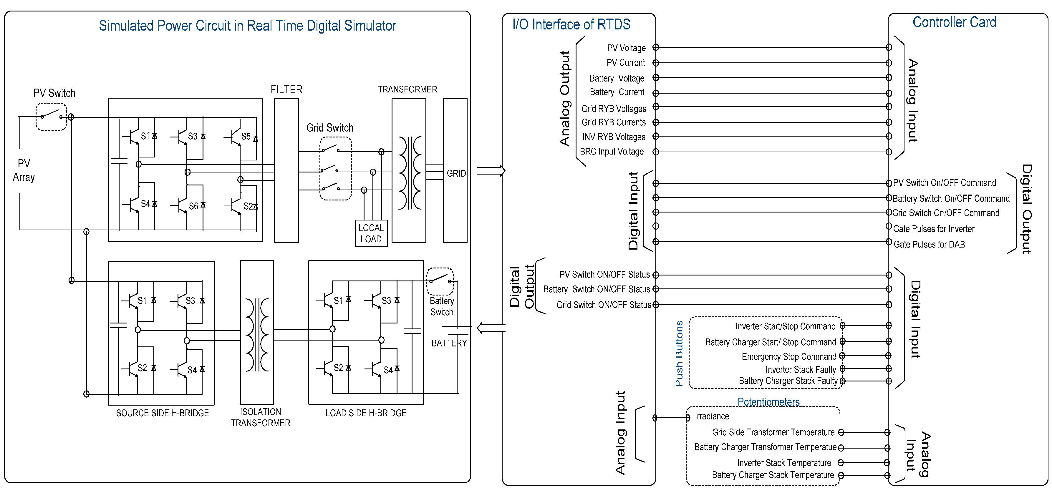
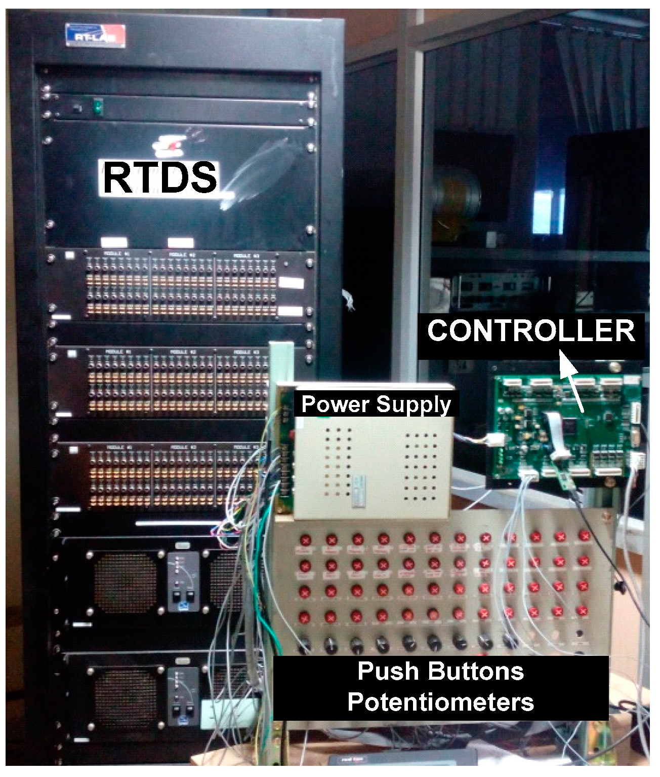
4. Hardware-in-the-Loop Simulation Setup for the Proposed System
4.1. Input-Output Channels of Real-Time Digital Simulator
4.2. Input-Output Channels of Controller Card
4.3. User Interface Panel Signals
4.4. Signals from Simulated Plant to Controller
4.5. Online Plant Parameter Modifications
5. Results and Discussions
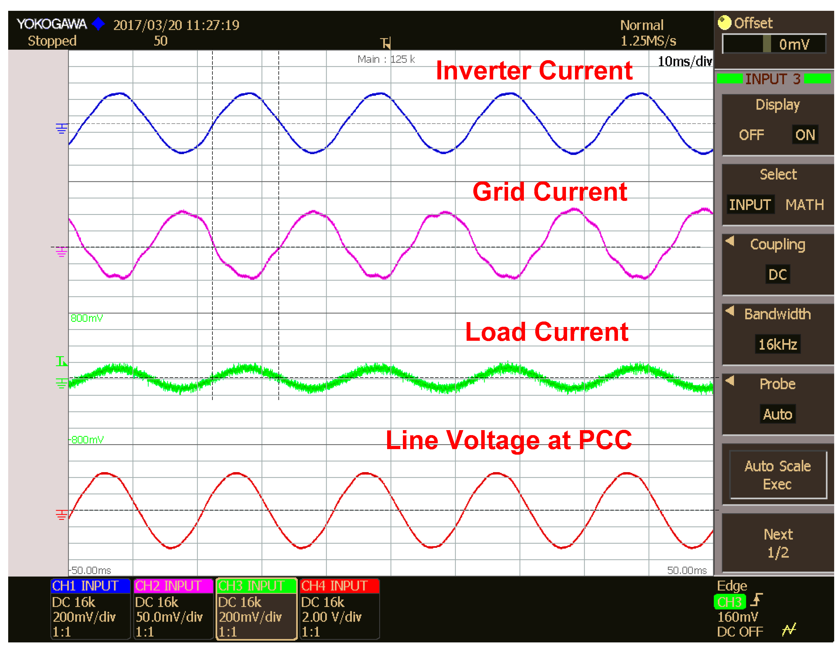
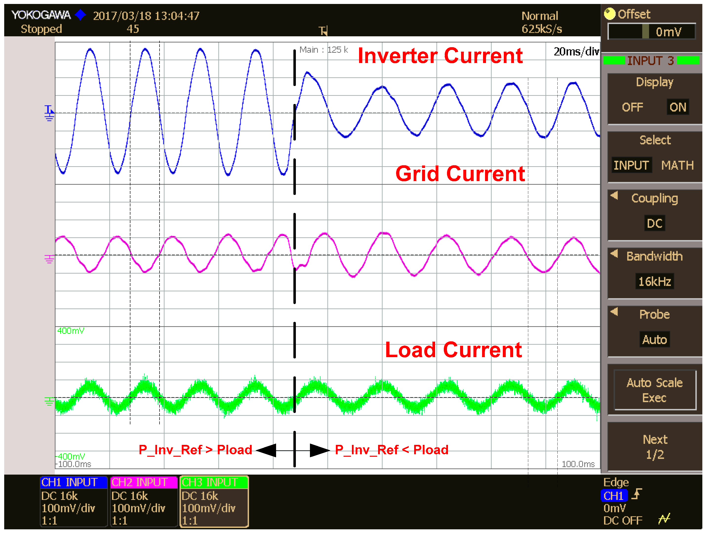
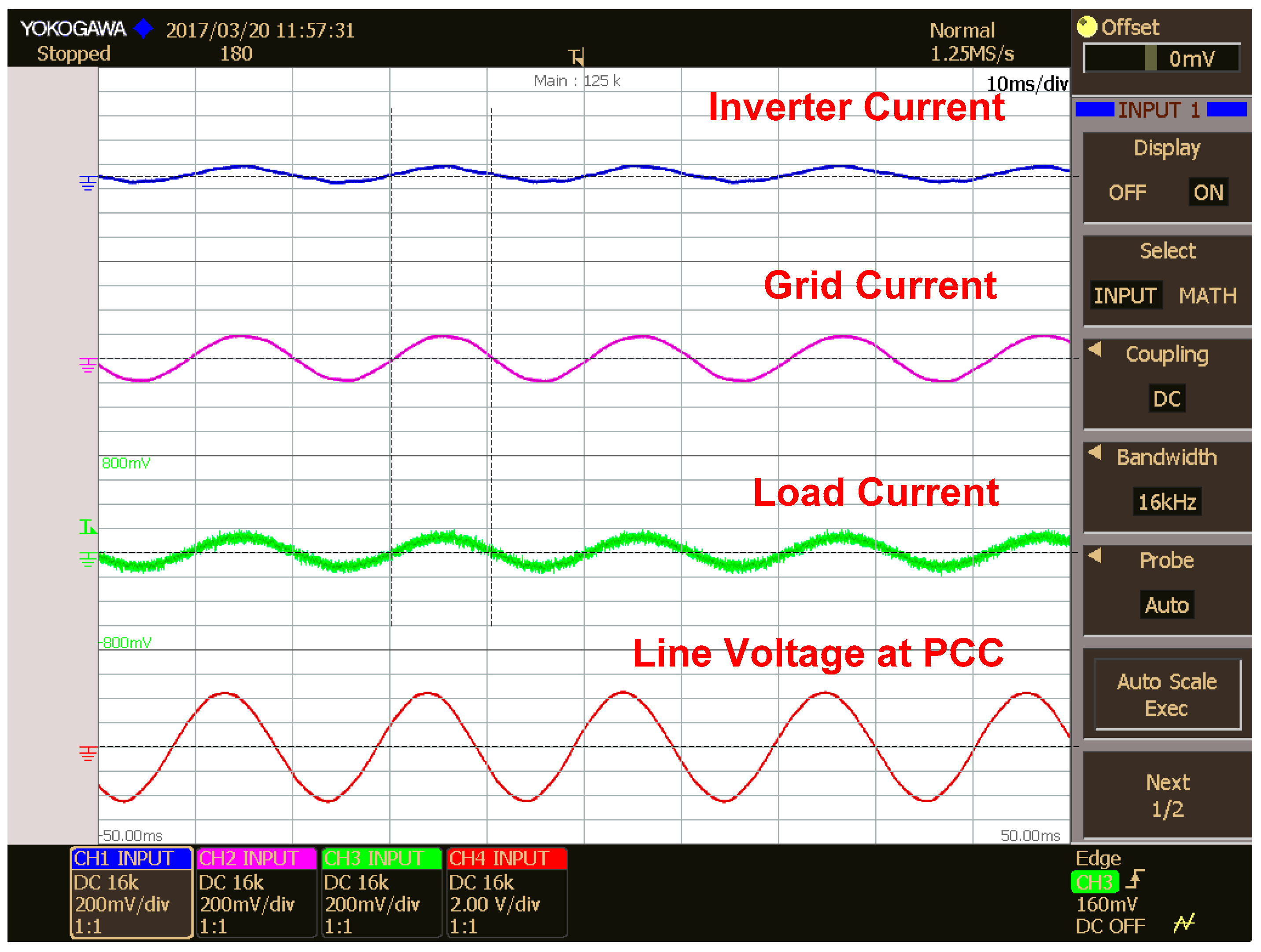
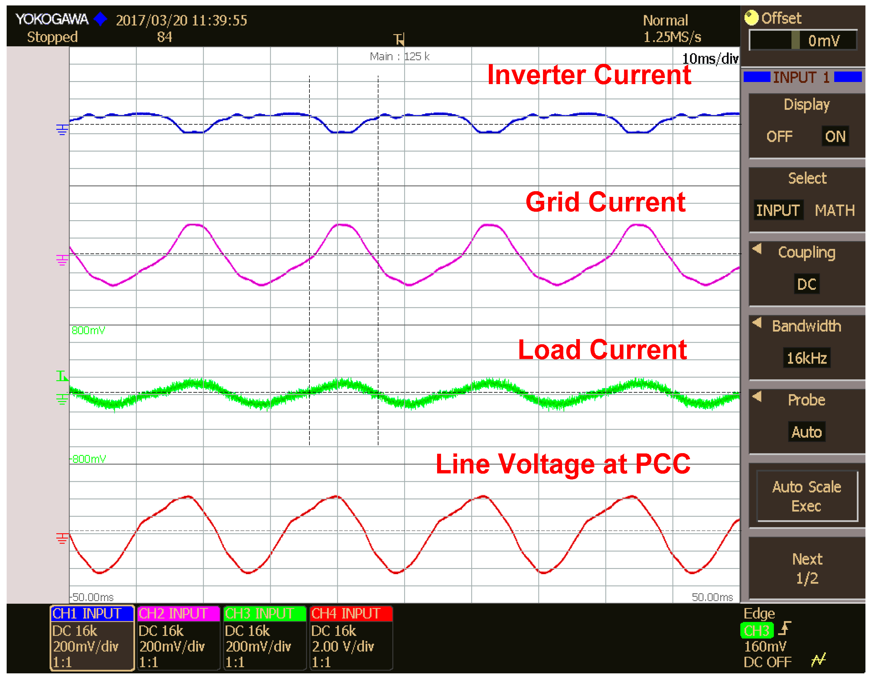
5.1. Inverter, Grid and Load Currents in Different Modes of Operation
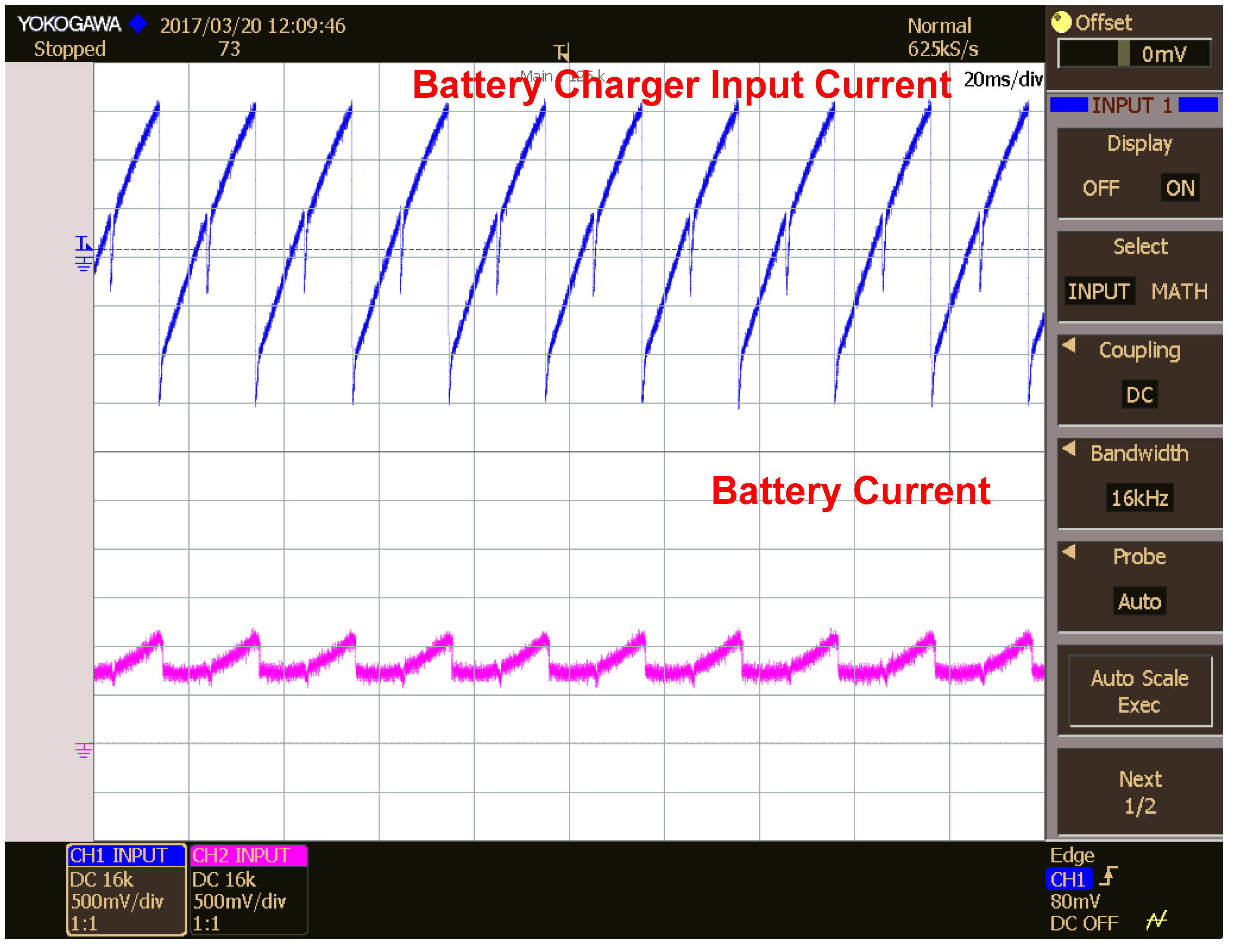
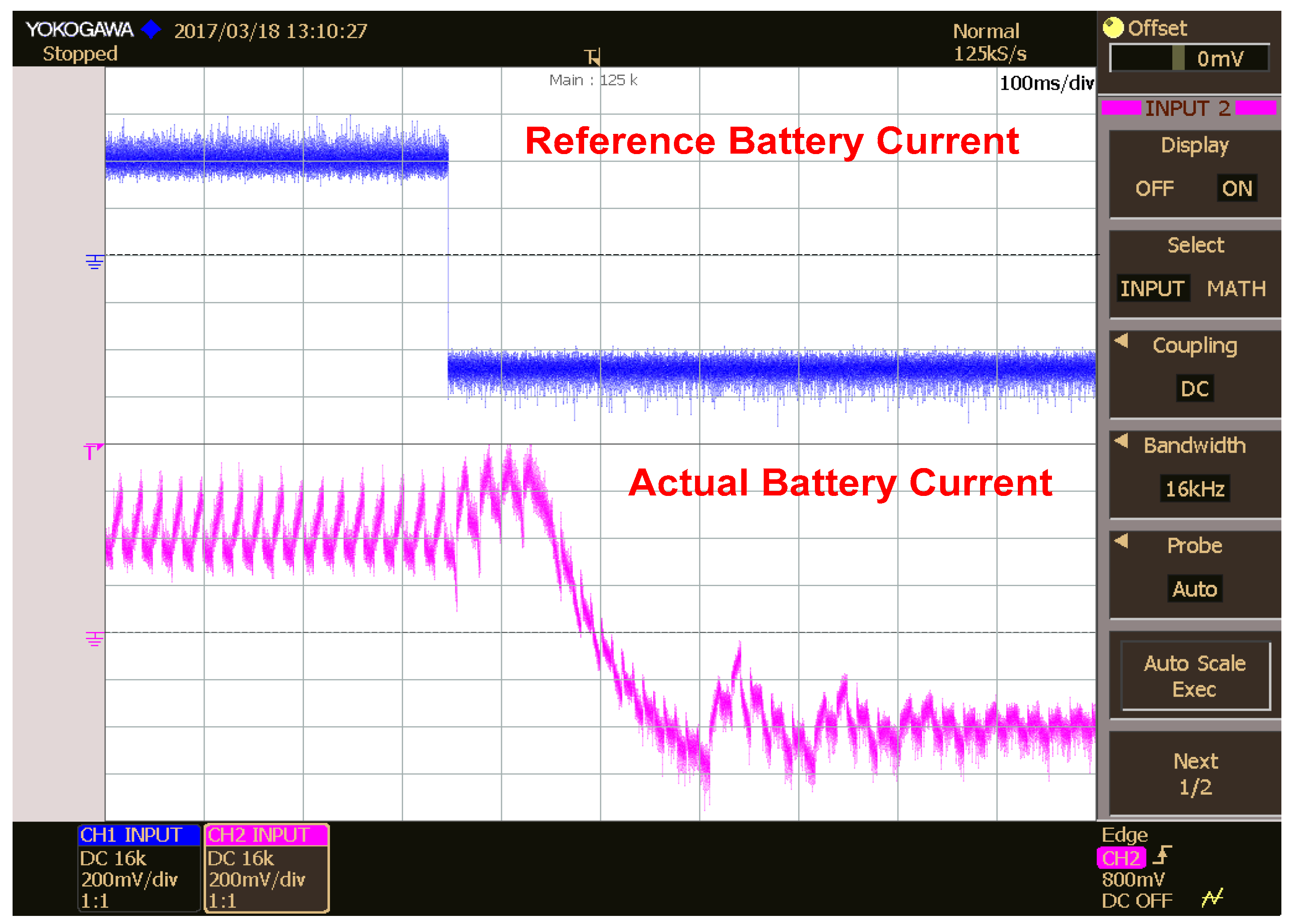
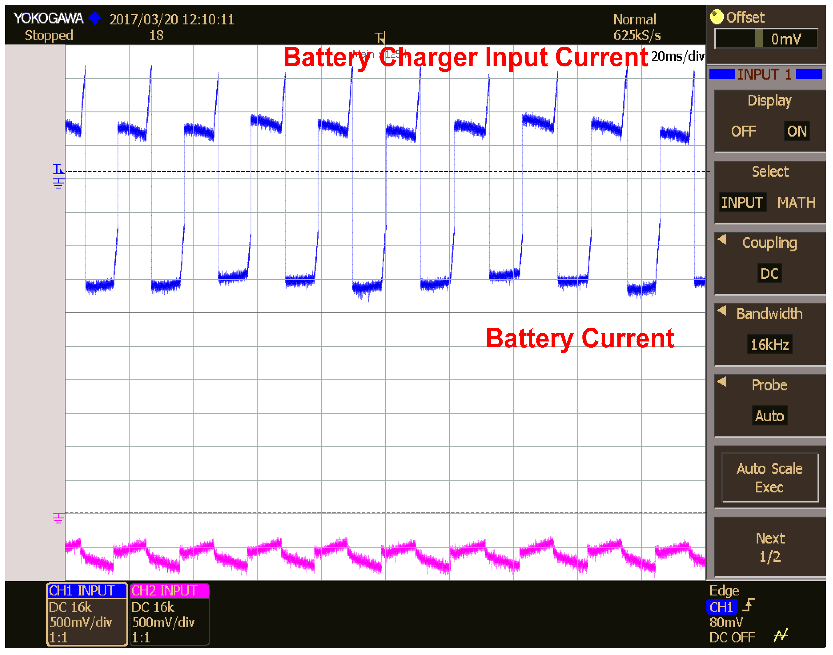
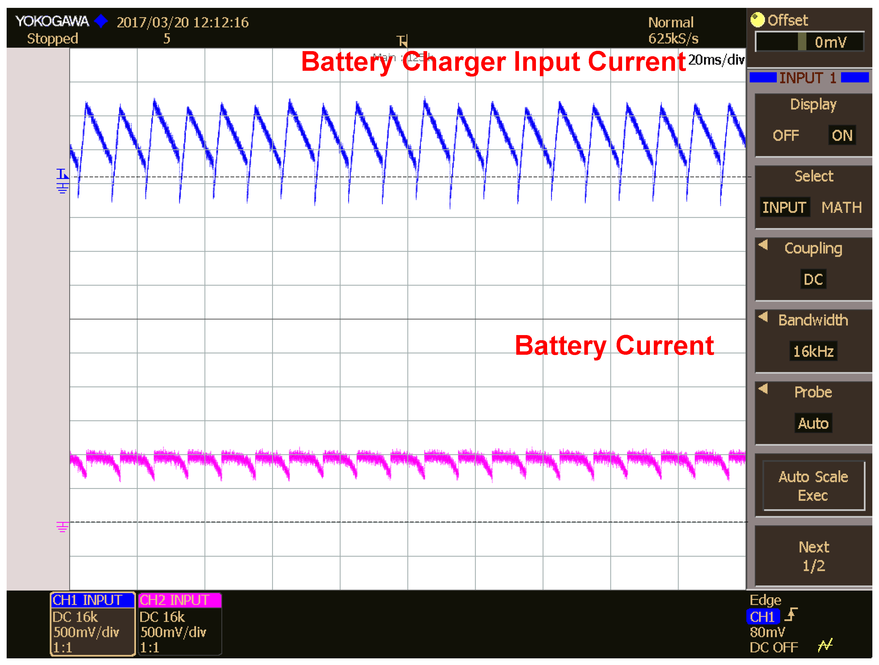
5.2. Battery Charger Input and Output Currents in Different Modes of Operation
6. Future Scope
7. Conclusions
Acknowledgments
Author Contributions
Conflicts of Interest
References
- Mihet-Popa, L.; Bindner, H. Simulation models developed for voltage control in a distribution network using energy storage systems for PV penetration. In Proceedings of the 39th Annual Conference of the IEEE Industrial Electronics Society—IECON’13, Vienna, Austria, 10–13 November 2013; pp. 7487–7492. [Google Scholar]
- El Khateb, A.; Rahim, N.A.; Selvaraj, J. Ćuk-Buck Converter for Standalone Photovoltaic System. J. Clean Energy Technol. 2013, 1, 69–74. [Google Scholar] [CrossRef]
- Wu, T.; Xiao, Q.; Wu, L.; Zhang, J.; Wang, M. Study and implementation on batteries charging method of Micro-Grid photovoltaic systems. Smart Grid Renew. Energy 2011, 204, 324–329. [Google Scholar] [CrossRef]
- Choi, H.; Jang, M.; Ciobotaru, M.; Agelidis, V.G. Hybrid energy storage for large PV systems using bidirectional high-gain converters. In Proceedings of the 2016 IEEE International Conference on Industrial Technology (ICIT), Taipei, Taiwan, 14–17 March 2016; pp. 425–430. [Google Scholar]
- Shi, Y.; Li, R.; Xue, Y.; Li, H. Optimized operation of current-fed dual active bridge DC–DC converter for PV applications. IEEE Trans. Ind. Electron. 2015, 62, 6986–6995. [Google Scholar] [CrossRef]
- Bharathi, K.; Sasikumar, M. Voltage Compensation of Smart Grid using Bidirectional Intelligent Semiconductor Transformer and PV Cell. Indian J. Sci. Technol. 2016, 9, 1–8. [Google Scholar] [CrossRef]
- Mihet-Popa, L.; Koch-Ciobotaru, C.; Isleifsson, F.; Bindner, H. Development of tools for DER Components in a distribution network. In Proceedings of the 2012 XXth International Conference on Electrical Machines (ICEM), Marseille, France, 2–5 September 2012; pp. 1022–1031. [Google Scholar]
- Chen, M.; Rincon-Mora, G.A. Accurate electrical battery model capable of predicting runtime and I-V performance. IEEE Trans. Energy Convers. 2006, 21, 504–511. [Google Scholar] [CrossRef]
- MathWorks. Available online: https://in.mathworks.com/help/physmod/sps/powersys/ref/battery.html;jsessionid=96072057f2374167c734b7a8e92d (accessed on 15 June 2017).
- Koch-Ciobotaru, C.; Mihet-Popa, L.; Isleifsson, F.; Bindner, H. Simulation Model developed for a Small-Scale PV-System in a Distribution Network. In Proceedings of the 7th International Symposium on Applied Computational Intelligence and Informatics—IEEE SACI 2012, Timisoara, Romania, 24–26 May 2012; pp. 257–261. [Google Scholar]
- Rahman, S.A.; Varma, R.K.; Vanderheide, T. Generalised model of a photovoltaic panel. IET Renew. Power Gener. 2014, 8, 217–229. [Google Scholar] [CrossRef]
- Jeong, D.K.; Kim, H.S.; Baek, J.W.; Kim, J.Y.; Kim, H.J. Dual active bridge converter for Energy Storage System in DC microgrid. In Proceedings of the 2016 IEEE Conference and Expo Transportation Electrification Asia-Pacific (ITEC Asia-Pacific), Busan, Korea, 1–4 June 2016; pp. 152–156. [Google Scholar]
- Dutta, S.; Hazra, S.; Bhattacharya, S. A Digital Predictive Current-Mode Controller for a Single-Phase High-Frequency Transformer-Isolated Dual-Active Bridge DC-to-DC Converter. IEEE Trans. Ind. Electron. 2016, 63, 5943–5952. [Google Scholar] [CrossRef]
- Kumar, N.; Saha, T.K.; Dey, J. Sliding-mode control of PWM dual inverter-based grid-connected PV system: Modeling and performance analysis. IEEE J. Emerg. Sel. Top. Power Electron. 2016, 4, 435–444. [Google Scholar] [CrossRef]
- Toodeji, H.; Farokhnia, N.; Riahy, G.H. Integration of PV module and STATCOM to extract maximum power from PV. In Proceedings of the International Conference on Electric Power and Energy Conversion Systems, Sharjah, UAE, 10–12 November 2009; pp. 1–6. [Google Scholar]
- Serban, E.; Ordonez, M.; Pondiche, C.; Feng, K.; Anun, M.; Servati, P. Power management control strategy in photovoltaic and energy storage for off-grid power systems. In Proceedings of the 2016 IEEE 7th International Symposium on Power Electronics for Distributed Generation Systems (PEDG), Vancouver, BC, Canada, 27–30 June 2016; pp. 1–8. [Google Scholar]
- Sikkabut, S.; Mungporn, P.; Ekkaravarodome, C.; Bizon, N.; Tricoli, P.; Nahid-Mobarakeh, B.; Thounthong, P. Control of High-Energy High-Power Densities Storage Devices by Li-ion Battery and Supercapacitor for Fuel Cell/Photovoltaic Hybrid Power Plant for Autonomous System Applications. IEEE Trans. Ind. Appl. 2016, 52, 4395–4407. [Google Scholar] [CrossRef]
- Merabet, A.; Ahmed, K.T.; Ibrahim, H.; Beguenane, R.; Ghias, A.M. Energy Management and Control System for Laboratory Scale Microgrid Based Wind-PV-Battery. IEEE Trans. Sustain. Energy 2017, 8, 145–154. [Google Scholar] [CrossRef]
- Lemaire, M.; Sicard, P.; Belanger, J. Prototyping and Testing Power Electronics Systems Using Controller Hardware-In-the-Loop (HIL) and Power Hardware-In-the-Loop (PHIL) Simulations. In Proceedings of the Vehicle Power and Propulsion Conference (VPPC), Montreal, QC, Canada, 19–22 October 2015; pp. 1–6. [Google Scholar]
- Saponara, S.; Fanucci, L.; Bernardo, F.; Falciani, A. Predictive diagnosis of high-power transformer faults by networking vibration measuring nodes with integrated signal processing. IEEE Trans. Instrum. Measure. 2016, 65, 1749–1760. [Google Scholar] [CrossRef]
- Saponara, S.; Bacchillone, T. Network architecture, security issues, and hardware implementation of a home area network for smart grid. J. Comput. Netw. Commun. 2012, 2012, 534512. [Google Scholar] [CrossRef]
- Sridhar, V.; Umashankar, S. A comprehensive review on CHB MLI based PV inverter and feasibility study of CHB MLI based PV-STATCOM. Renew. Sustain. Energy Rev. 2017, 78, 138–156. [Google Scholar] [CrossRef]
- Das, V.; Sanjeevikumar, P.; Karthikeyan, V.; Rajasekar, S.; Blaabjerg, F.; Pierluigi, S. Recent Advances and Challenges of Fuel Cell Based Power System Architectures and Control—A Review. Renew. Sustain. Energy 2017, 73, 10–18. [Google Scholar] [CrossRef]


| SL. NO | Parameter | Value | Units | Remarks |
|---|---|---|---|---|
| 1 | Grid Voltage | 11 | kV | 3-Phase |
| 2 | Grid Frequency (F) | 50 | Hz | |
| 3 | PCC Voltage | 415 | V | Rated Voltage of Local load |
| 4 | Maximum PV-Inverter Power | 100 | kW | |
| 5 | Backup Power | 25 | kW | 25% of PV-Inverter Power |
| 6 | Minimum Back Up Time | 4 | h |
| SL. NO | Parameter | Value | Units | Remarks |
|---|---|---|---|---|
| 1 | Power Rating | 100 | kW | |
| 2 | PCC Voltage (Vpcc) | 415 | V | |
| 3 | Inverter RMS Current | 140 | A | Power/(1.732 PCC Voltage) |
| 4 | Maximum Filter Drop | 6 | % | Drop across L-C-L Filter |
| 5 | Inverter Voltage (Vinv) | 440 | V | PCC Voltage + filter Drop |
| 6 | Minimum DC Link Voltage | 620 | V | Vdc = (Vinv/0.71) With SPWM |
| Selection of Filter Capacitor (C) | ||||
| 7 | Maximum Reactive Power(Qc) | 5 | % | 5% of 500 kVA i.e., 25 kVAR |
| 8 | Current Rating of Capacitor (Ic) | 11.5 | A | Qc/PCC Voltage |
| 9 | Maximum Capacitance | 85 | uF | Ic/(2 * pi * F * Vpcc) |
| 10 | Selected Value of Capacitance | 80 | uF | <Maximum capacitance |
| Selection of Inverter Side Filter Inductor (L1) | ||||
| 11 | Corner Frequency selected (Fc) | 1.25 | kHZ | Switching Frequency/4 |
| 12 | Inductance of Inductor L1 | 203 | uH | Fc = 1/[2 * pi * √(LC)] |
| 13 | % Voltage Drop in Inductor L1 | 2.1 | % | [Irms × (2 * pi * F * L1)]/Vpcc |
| Selection of Grid Side Filter Inductor (L2) | ||||
| 14 | Maximum Drop allowed across L2 | 3.9 | % | Max Drop-% Drop across L1 |
| 15 | Maximum Inductance of L2 | 382 | uH | (3.9% * Vpcc)/[Irms * 2 * pi * F] |
| SL. NO | Parameter | Value | Units | Remarks |
|---|---|---|---|---|
| Selection of Battery | ||||
| 1 | Nominal Voltage of Battery (Vnom) | 350 | V | |
| 2 | Maximum Battery Voltage | 406 | V | 116% of Vnom for Li-Ion battery |
| 3 | Minimum battery Voltage | 306 | V | >87.5% for Safe operation |
| 4 | Battery Rated Power | 25 | kW | 25% of PV-Inverter rating |
| 5 | Maximum Battery Current | 72 | A | Battery Power/Vnom |
| 5 | Minimum Backup time | 4 | h | |
| 6 | Ah Rating of Battery | 288 | Ah | Current X Backup Time |
| 7 | Battery Charging time | 8 | H | PV Power availability time |
| 8 | Charging Current (I_Charging) | 36 | A | Ah Rating/Charging Time |
| 9 | PV Power Required for Charging | 12.5 | kW | Vnom × I_charging |
| SL. NO | Parameter | Value | Units | Remarks |
|---|---|---|---|---|
| PV Array Requirement | ||||
| 1 | Minimum Power Requirement | 113 | kW | PV Inverter + Charging Power |
| 2 | Minimum PV Voltage (V_PV_Min) | 620 | V | Vdc Minimum Refer Table 2 |
| 3 | Maximum PV Current | 182 | A | Power/V_PV_Min |
| Details of Selected PV Module | ||||
| 4 | Make | Sunpower | ||
| 5 | Type Number | SPR-435NE-WHT-D | ||
| 6 | Operating Temperature Range | 25–55 °C | ||
| Electrical Ratings of Selected PV Module at 25 °C | ||||
| 7 | Power Rating of Each Module | 435 | W | From Datasheet |
| 8 | Open Circuit Voltage (Voc) | 85.6 | V | |
| 9 | Short Circuit Current (Isc) | 6.43 | A | |
| 10 | MPP Voltage (Vmpp | 72.9 | V | |
| 11 | MPP Current (Impp) | 5.97 | A | |
| Temperature Coefficients of Selected PV Module | ||||
| 12 | Temperature Coefficient for power | −0.38 | %/K | From Datasheet |
| 13 | Temperature Coefficient for Voltage | −233.5 | mV/K | |
| 14 | Temperature Coefficient for Voltage | 3.5 | mA/K | |
| Electrical Ratings of Selected PV Module at 55 °C | ||||
| 15 | Open Circuit Voltage (Voc) | 78.59 | V | Derived From Values at 25 °C and the Temperature Coefficients |
| 16 | Short Circuit Current (Isc) | 6.535 | A | |
| 17 | MPP Voltage (Vmpp) | 65.89 | V | |
| 18 | MPP Current (Impp) | 6.08 | A | |
| Selected PV Module Electrical Ratings in the Operating Temperature Range | ||||
| 19 | Minimum Voltage (Vmod_min) | 65.89 | V | Vmpp at 55 °C |
| 20 | Maximum Voltage (Vmod_max) | 85.6 | V | Voc at 25 °C |
| 21 | Maximum Current (Imod_max) | 6.535 | A | Isc at 55 °C |
| 22 | Maximum power (Pmod_max) | 435 | W | From Datasheet |
| Electrical Ratings of PV Array | ||||
| 23 | Minimum No. of Modules required (N) | 260 | No’s | PV power/Pmod_max |
| 24 | Minimum No. of Modules in Series (Nse) | 10 | No’s | V_PV_Min/Vmod_min |
| 25 | No. of Modules in parallel (Np) | 26 | No’s | N/Nse |
| 26 | Minimum Voltage of PV Array | 658.9 | V | Vmod_min × Nse |
| 27 | Maximum Voltage of PV Array | 856 | V | Vmod_max × Nse |
| 28 | Maximum power from PV Array | 113 | kW | Nse × Np × Pmod_max |
| SL. NO | Parameter | Value | Units | Remarks |
|---|---|---|---|---|
| Selection of Battery | ||||
| 1 | Battery Charger Rated Power | 25 | kW | Battery discharging capacity |
| 2 | Battery Charger Input Voltage | 658–856 | V | PV Operating Range |
| 3 | Battery Charger Output Voltage | 306–406 | V | Battery Operating Voltage |
| 4 | Isolation Transformer Turns Ratio | 1:2 | ||
| 5 | Transformer Primary Current | 38 | A | Rated Power/Min Input Voltage |
| 6 | Transformer Secondary Current | 82 | A | Rated Power/Min Output Voltage |
| 7 | Minimum kVA of Primary | 32.5 | kVA | Primary Max Voltage × Current |
| 8 | Minimum kVA of Secondary | 33.3 | kVA | Secondary Max Voltage × Current |
| 9 | Selected Transformer KVA Rating | 35 | kVA | More than minimum kVA |
© 2017 by the authors. Licensee MDPI, Basel, Switzerland. This article is an open access article distributed under the terms and conditions of the Creative Commons Attribution (CC BY) license (http://creativecommons.org/licenses/by/4.0/).
Share and Cite
Vavilapalli, S.; Padmanaban, S.; Subramaniam, U.; Mihet-Popa, L. Power Balancing Control for Grid Energy Storage System in Photovoltaic Applications—Real Time Digital Simulation Implementation. Energies 2017, 10, 928. https://doi.org/10.3390/en10070928
Vavilapalli S, Padmanaban S, Subramaniam U, Mihet-Popa L. Power Balancing Control for Grid Energy Storage System in Photovoltaic Applications—Real Time Digital Simulation Implementation. Energies. 2017; 10(7):928. https://doi.org/10.3390/en10070928
Chicago/Turabian StyleVavilapalli, Sridhar, Sanjeevikumar Padmanaban, Umashankar Subramaniam, and Lucian Mihet-Popa. 2017. "Power Balancing Control for Grid Energy Storage System in Photovoltaic Applications—Real Time Digital Simulation Implementation" Energies 10, no. 7: 928. https://doi.org/10.3390/en10070928
APA StyleVavilapalli, S., Padmanaban, S., Subramaniam, U., & Mihet-Popa, L. (2017). Power Balancing Control for Grid Energy Storage System in Photovoltaic Applications—Real Time Digital Simulation Implementation. Energies, 10(7), 928. https://doi.org/10.3390/en10070928